EP2522971B1 - Method and assembly for high angle of attack process parameter sensors - Google Patents
Method and assembly for high angle of attack process parameter sensors Download PDFInfo
- Publication number
- EP2522971B1 EP2522971B1 EP12167225.7A EP12167225A EP2522971B1 EP 2522971 B1 EP2522971 B1 EP 2522971B1 EP 12167225 A EP12167225 A EP 12167225A EP 2522971 B1 EP2522971 B1 EP 2522971B1
- Authority
- EP
- European Patent Office
- Prior art keywords
- flow
- sensor
- airfoil body
- assembly
- fluid
- Prior art date
- Legal status (The legal status is an assumption and is not a legal conclusion. Google has not performed a legal analysis and makes no representation as to the accuracy of the status listed.)
- Active
Links
Images


Classifications
-
- G—PHYSICS
- G01—MEASURING; TESTING
- G01K—MEASURING TEMPERATURE; MEASURING QUANTITY OF HEAT; THERMALLY-SENSITIVE ELEMENTS NOT OTHERWISE PROVIDED FOR
- G01K13/00—Thermometers specially adapted for specific purposes
- G01K13/02—Thermometers specially adapted for specific purposes for measuring temperature of moving fluids or granular materials capable of flow
- G01K13/028—Thermometers specially adapted for specific purposes for measuring temperature of moving fluids or granular materials capable of flow for use in total air temperature [TAT] probes
Definitions
- the field of the invention relates generally to process parameter sensing devices and more specifically, to an assembly and method of sensing a process parameter.
- At least some known total air temperature (TAT) sensors are limited in their ability to maintain accurate measuring capability at high angles of attack.
- An airfoil channeling airflow towards a sensing element of the sensor can cause a flow separation on the airfoil if the angle of attack is increased beyond a certain angle for example, +/- 15 degrees. The separation can result in an extreme recovery error and convective film variation.
- US 2006/0056489 A1 relates to a sensor for measuring total air temperature.
- WO 94/25842 A1 relates to a temperature sensor having an integral debris guard.
- US 7,845,222 B1 relates to a method and assembly for sensing process parameters.
- a sensing assembly is provided in accordance with claim 1 herein.
- a method of sensing a process parameter is provided in accordance with claim 7 herein.
- a process sensing system in yet another embodiment, includes a first extension member and a second extension member extending parallelly from a base and spaced apart by a flow channel and a sensor assembly extending between the first and second extension members.
- the sensor assembly includes a center airfoil body and a sensor element positioned downstream of the center airfoil body, a first airfoil body spaced apart from the center airfoil body by a first flow channel, the first airfoil body including a concave surface facing the center airfoil body, and a second airfoil body spaced apart from the center airfoil body by a second flow channel, the second airfoil body including a convex surface facing the center airfoil body.
- Embodiments of the present invention describe a gas turbine engine fan inlet temperature sensor capable of operating accurately over an angle of attack range of ⁇ 30°.
- the fan inlet temperature sensor described herein uses a symmetrical airfoil for the extension member that extends from a wall of the fan inlet, however embodiments of the invention are not to be limited to only symmetrical airfoils.
- Flow separation on the extension member airfoil at large angles of attack can result in an extreme recovery error, time response, and convective film variation.
- Managing the flow separation is critical in consistent sensor performance especially at higher mach numbers.
- Embodiments of the present invention straighten the airflow that reaches the sensing element using a "V" channel with rounded tip profiles.
- the "V” channel forces air to directly impinge on the sensing element, because the airfoil is symmetrical, the air flow stays attached to the wall of the "V" channel until the angle of attack reaches approximately ⁇ 50°.
- the flow path generates an area of high pressure as well as an area of low pressure. This pressure differential forces the air flow to change direction. This direction change ensures the massive water particles and dust particles can not directly impact the sensing element.
- the mass of the water and dust is so large that momentum of these particles makes it impossible to make the same sharp turn that the air flow is able to make.
- the outer sheath decreases the air velocity around the sensing element, this reduction in air velocity raises the temperature of the air to almost that of the true total temperature.
- the difference between the sensed temperature and that of the true total temperature of the air is then used to calculate the recovery error of the sensor.
- the outer sheath also promotes a large uniform convective film on the outside of the sensing element. This large uniform convective film decreases the transient response of the sensing element as well as reduces excitation error and conduction error.
- the pressure differential that drives airflow to the sensing element is generated using three relatively smaller airfoils.
- the fan inlet temperature sensing element is a resistance temperature detector (RTD) that measures the engine inlet total air temperature. It is a hermetically sealed, dual element, electrical device that exhibits a change in resistance proportional to air temperature changes. Signals from both elements are routed to the Full Authority Digital Engine Control (FADEC). A single electrical connector provides the electrical interface.
- the sensor assembly uses electric heaters powered by the electric anti-ice system to prevent the formation of ice on the sensor assembly housing under service conditions.
- the sensor assembly is constructed from hardened Inconel 718, which is sufficiently hard so as not to be damaged when exposed to sand and dust particle impingement. The area most susceptible to sand and dust impingement, the sensing element, is protected by a center airfoil body of the sensor assembly. All water and sand particles are separated out by the airfoil design.
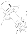
- FIG. 1 is a perspective view of a sensing assembly 100 in accordance with an exemplary embodiment of the present invention.
- sensing assembly 100 includes a base 102 and a sensor assembly 104.
- Sensor assembly 104 includes a sensing element 106 (not visible in FIG. 1 ), a first flow channel 108 and a second flow channel 110.
- Sensor assembly 104 also includes an extension member 112 extending between base 102 and sensor assembly 104.
- Base 102 includes a flange 114 and a boss 116.
- Flange 114 is configured to couple sensing assembly 100 to a wall of a process conduit, for example, an inlet duct of a gas turbine engine.
- Boss 116 is configured to receive electrical wiring within to permit coupling electrical components within sensing assembly 100 to power sources and/or control devices (not shown).
- a connector housing 118 is configured to matingly engage boss 116.
- Connector housing 118 includes a connector 120 through which wires pass from connector housing 118 to a cable (not shown).
- FIG. 2 is a plan view of extension member 112 (shown in FIG. 1 ) taken along lines 2-2 (also shown in FIG. 1 ).
- extension member 112 includes a first leg 202 and a second leg 204 that defines a flow channel 206 therebetween.
- Flow channel 206 includes a converging V-channel segment 208 upstream with respect to a straightening segment 210.
- a flow of fluid 212 enters converging V-channel segment 208 and is accelerated into straightening segment 210.
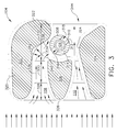
- FIG. 3 is a side elevation view of sensor assembly 104 (shown in FIG. 1 ) taken along lines 3-3 (also shown in FIG. 1 ).
- sensor assembly 104 includes a first airfoil body 302, a second airfoil body 304, and a center airfoil body 306.
- first airfoil body 302, second airfoil body 304, and center airfoil body 306 extend orthogonally with respect to extension member 112.
- extension member 112 is oriented vertically when properly installed for use and therefore first airfoil body 302, second airfoil body 304, and center airfoil body 306 are oriented substantially horizontally when properly installed for use.
- sensing assembly 100 may be operated at pitch angles that change the orientation of extension member 112, first airfoil body 302, second airfoil body 304, and center airfoil body 306 with respect to the vertical and horizontal orientations.
- certain operating conditions cause airflow to enter sensor assembly 104 at various angles, including up to approximately 50° incline and decline (pitch) and/or a rotation about sensor assembly 104 (yaw).
- Sensor assembly 104 further includes sensing element 106 and a sheath 308 that at least partially surrounds sensing element 106.
- sensing element 106 has a substantially cylindrical body and sheath 308 is also substantially cylindrical.
- An outer surface 310 of sensing element 106 and an inner surface 312 of sheath 308 define a gap 314 between them.
- a first upstream opening 316 in sheath 308 permits fluid entry into gap 314 and a second downstream opening 318 in sheath 308 permits fluid egress from gap 314.
- First airfoil body 302 includes a substantially J-shaped cross-section with a longer leg 320 of the "J" aligned into the direction of fluid flow and a shorter leg 322 oriented towards second airfoil body 304.
- First airfoil body 302 includes a concave surface facing center airfoil body 306.
- Second airfoil body 304 includes a triangular cross-section with an apex 324 of the triangle proximate sensing element 106 and sheath 308.
- Second airfoil body 304 includes a convex surface facing center airfoil body 306.
- Center airfoil body 306 includes a substantially isosceles triangle shape with an apex 326 of center airfoil body 304 aligned into the direction of fluid flow.
- First airfoil body 302 and center airfoil body 306 define first flow channel 108 to include a converging segment 328, a straightening segment 330, and a turning segment 332.
- Turning segment 332 includes a turn radius 334 configured to separate particles from a flow 336 entering turning segment 332.
- flow 336 will separate into a particle-laden stream 338 and a particle-reduced stream 340.
- Particle-laden stream 338 will pass between sheath 308 and first airfoil body 302 and not be introduced into gap 314 or impinge sensing element 106.
- Particle-reduced stream 340 will be able to turn sufficiently to be directed into upstream opening 316 to be measured by sensing element 106.
- Flow 336 is facilitated being introduced into opening 316 by an area 342 of relatively high pressure generated in turning segment 332 by a shape of flow channel 108. Area 342 is generated upstream from sensing element 106 in turning segment 332.
- Second airfoil body 304 and center airfoil body 306 define second flow channel 110 therebetween.
- Second flow channel 110 is configured to generate a low pressure area 344 downstream of sensing element 106.
- FIG. 4 is a flow diagram of a method 400 of sensing a process parameter.
- method 400 includes channeling 402 a flow of fluid through a first flow passage defined between a first airfoil body and a center airfoil body, channeling 404 the flow of fluid through a second flow passage defined between a second airfoil body and the center airfoil body, turning 406 the flow of fluid in the first flow passage to facilitate separating the flow of fluid in the first flow passage into a first stream having relatively reduced particulates with respect to a second stream, and directing 408 the first stream to a sensor element.
- Method 400 optionally includes generating an area of relatively high pressure in the first flow passage and/or generating an area of relatively low pressure in the second flow passage.
- method 400 includes reducing a velocity of the flow of fluid exiting the first flow passage proximate the sensor element. In yet other embodiments, the velocity of the flow of fluid exiting the first flow passage is reduced proximate the sensor element using a sheath surrounding the sensor element. Method 400 may also include directing the flow of fluid exiting the first flow passage into an opening in a sheath surrounding the sensor element.
- the above-described embodiments of a method and assembly for sensing a process parameter provides a cost-effective and reliable means for reducing effects of direct water and/or ice impingement on the sensor, angle of attack, and time response. More specifically, the methods and assembly described herein facilitate separating water and/or ice from a flow of fluid. In addition, the above-described methods and assembly facilitate sampling a low velocity portion of the flow of fluid without moving parts in the process sensor assembly. As a result, the methods and assembly described herein facilitate measuring parameters of a process in a cost-effective and reliable manner.
Landscapes
- Physics & Mathematics (AREA)
- General Physics & Mathematics (AREA)
- Measuring Temperature Or Quantity Of Heat (AREA)
- Measuring Fluid Pressure (AREA)
Description
- The field of the invention relates generally to process parameter sensing devices and more specifically, to an assembly and method of sensing a process parameter.
- At least some known total air temperature (TAT) sensors are limited in their ability to maintain accurate measuring capability at high angles of attack. An airfoil channeling airflow towards a sensing element of the sensor can cause a flow separation on the airfoil if the angle of attack is increased beyond a certain angle for example, +/- 15 degrees. The separation can result in an extreme recovery error and convective film variation.
-
US 2006/0056489 A1 relates to a sensor for measuring total air temperature. -
WO 94/25842 A1 -
US 7,845,222 B1 relates to a method and assembly for sensing process parameters. - In one aspect, a sensing assembly is provided in accordance with claim 1 herein.
- In another aspect, a method of sensing a process parameter is provided in accordance with claim 7 herein.
- In yet another embodiment, a process sensing system includes a first extension member and a second extension member extending parallelly from a base and spaced apart by a flow channel and a sensor assembly extending between the first and second extension members. The sensor assembly includes a center airfoil body and a sensor element positioned downstream of the center airfoil body, a first airfoil body spaced apart from the center airfoil body by a first flow channel, the first airfoil body including a concave surface facing the center airfoil body, and a second airfoil body spaced apart from the center airfoil body by a second flow channel, the second airfoil body including a convex surface facing the center airfoil body.
-
-
Figures 1-4 show exemplary embodiments of the method and assembly described herein. -
Figure 1 is a perspective view of a sensing assembly in accordance with an exemplary embodiment of the present invention; -
FIG. 2 is a plan view of the extension member shown inFIG. 1 taken along lines 2-2 also shown inFIG. 1 ; -
FIG. 3 is a side elevation view of sensor assembly shown inFIG. 1 taken along lines 3-3 also shown inFIG. 1 ; and -
FIG. 4 is a flow diagram of a method of sensing a process parameter. - The following detailed description illustrates embodiments of the invention by way of example and not by way of limitation. It is contemplated that the invention has general application to analytical and methodical embodiments of sensing process parameters in industrial, commercial, and residential applications.
- As used herein, an element or step recited in the singular and proceeded with the word "a" or "an" should be understood as not excluding plural elements or steps, unless such exclusion is explicitly recited. Furthermore, references to "one embodiment" of the present invention are not intended to be interpreted as excluding the existence of additional embodiments that also incorporate the recited features.
- Embodiments of the present invention describe a gas turbine engine fan inlet temperature sensor capable of operating accurately over an angle of attack range of ± 30°. The fan inlet temperature sensor described herein uses a symmetrical airfoil for the extension member that extends from a wall of the fan inlet, however embodiments of the invention are not to be limited to only symmetrical airfoils. Flow separation on the extension member airfoil at large angles of attack can result in an extreme recovery error, time response, and convective film variation. Managing the flow separation is critical in consistent sensor performance especially at higher mach numbers. Embodiments of the present invention straighten the airflow that reaches the sensing element using a "V" channel with rounded tip profiles.
- The "V" channel forces air to directly impinge on the sensing element, because the airfoil is symmetrical, the air flow stays attached to the wall of the "V" channel until the angle of attack reaches approximately ±50°. The flow path generates an area of high pressure as well as an area of low pressure. This pressure differential forces the air flow to change direction. This direction change ensures the massive water particles and dust particles can not directly impact the sensing element. The mass of the water and dust is so large that momentum of these particles makes it impossible to make the same sharp turn that the air flow is able to make. After the air flow has been turned, and the water and dust have been separated out of the air flow, the air flow is channeled into an outer sheath over the sensing element. The outer sheath decreases the air velocity around the sensing element, this reduction in air velocity raises the temperature of the air to almost that of the true total temperature. The difference between the sensed temperature and that of the true total temperature of the air is then used to calculate the recovery error of the sensor. The outer sheath also promotes a large uniform convective film on the outside of the sensing element. This large uniform convective film decreases the transient response of the sensing element as well as reduces excitation error and conduction error. The pressure differential that drives airflow to the sensing element is generated using three relatively smaller airfoils.
- The fan inlet temperature sensing element is a resistance temperature detector (RTD) that measures the engine inlet total air temperature. It is a hermetically sealed, dual element, electrical device that exhibits a change in resistance proportional to air temperature changes. Signals from both elements are routed to the Full Authority Digital Engine Control (FADEC). A single electrical connector provides the electrical interface. The sensor assembly uses electric heaters powered by the electric anti-ice system to prevent the formation of ice on the sensor assembly housing under service conditions. In various embodiments, the sensor assembly is constructed from hardened Inconel 718, which is sufficiently hard so as not to be damaged when exposed to sand and dust particle impingement. The area most susceptible to sand and dust impingement, the sensing element, is protected by a center airfoil body of the sensor assembly. All water and sand particles are separated out by the airfoil design.
-
Figure 1 is a perspective view of asensing assembly 100 in accordance with an exemplary embodiment of the present invention. In the exemplary embodiment,sensing assembly 100 includes abase 102 and asensor assembly 104.Sensor assembly 104 includes a sensing element 106 (not visible inFIG. 1 ), afirst flow channel 108 and asecond flow channel 110.Sensor assembly 104 also includes anextension member 112 extending betweenbase 102 andsensor assembly 104.Base 102 includes aflange 114 and aboss 116.Flange 114 is configured tocouple sensing assembly 100 to a wall of a process conduit, for example, an inlet duct of a gas turbine engine. Boss 116 is configured to receive electrical wiring within to permit coupling electrical components withinsensing assembly 100 to power sources and/or control devices (not shown). Aconnector housing 118 is configured to matingly engageboss 116.Connector housing 118 includes aconnector 120 through which wires pass fromconnector housing 118 to a cable (not shown). -
FIG. 2 is a plan view of extension member 112 (shown inFIG. 1 ) taken along lines 2-2 (also shown inFIG. 1 ). In the exemplary embodiment,extension member 112 includes afirst leg 202 and asecond leg 204 that defines aflow channel 206 therebetween.Flow channel 206 includes a converging V-channel segment 208 upstream with respect to a straighteningsegment 210. A flow offluid 212 enters converging V-channel segment 208 and is accelerated into straighteningsegment 210. -
FIG. 3 is a side elevation view of sensor assembly 104 (shown inFIG. 1 ) taken along lines 3-3 (also shown inFIG. 1 ). In the exemplary embodiment,sensor assembly 104 includes afirst airfoil body 302, asecond airfoil body 304, and acenter airfoil body 306. Also in the exemplary embodiment,first airfoil body 302,second airfoil body 304, andcenter airfoil body 306 extend orthogonally with respect toextension member 112. In one embodiment,extension member 112 is oriented vertically when properly installed for use and thereforefirst airfoil body 302,second airfoil body 304, andcenter airfoil body 306 are oriented substantially horizontally when properly installed for use. During operation however, in certainapplications sensing assembly 100 may be operated at pitch angles that change the orientation ofextension member 112,first airfoil body 302,second airfoil body 304, andcenter airfoil body 306 with respect to the vertical and horizontal orientations. In addition, certain operating conditions cause airflow to entersensor assembly 104 at various angles, including up to approximately 50° incline and decline (pitch) and/or a rotation about sensor assembly 104 (yaw). -
Sensor assembly 104 further includessensing element 106 and asheath 308 that at least partially surroundssensing element 106. In the exemplary embodiment, sensingelement 106 has a substantially cylindrical body andsheath 308 is also substantially cylindrical. Anouter surface 310 ofsensing element 106 and aninner surface 312 ofsheath 308 define agap 314 between them. A firstupstream opening 316 insheath 308 permits fluid entry intogap 314 and a seconddownstream opening 318 insheath 308 permits fluid egress fromgap 314. -
First airfoil body 302 includes a substantially J-shaped cross-section with alonger leg 320 of the "J" aligned into the direction of fluid flow and ashorter leg 322 oriented towardssecond airfoil body 304.First airfoil body 302 includes a concave surface facingcenter airfoil body 306.Second airfoil body 304 includes a triangular cross-section with an apex 324 of the triangleproximate sensing element 106 andsheath 308.Second airfoil body 304 includes a convex surface facingcenter airfoil body 306.Center airfoil body 306 includes a substantially isosceles triangle shape with an apex 326 ofcenter airfoil body 304 aligned into the direction of fluid flow. -
First airfoil body 302 andcenter airfoil body 306 definefirst flow channel 108 to include a convergingsegment 328, a straighteningsegment 330, and a turning segment 332. Turning segment 332 includes aturn radius 334 configured to separate particles from aflow 336 entering turning segment 332. Asflow 336 enters turning segment 332 and begins to turn, particles, moisture droplets, and ice, because of their momentum, will not be able to turn as rapidly as the fluid itself. Accordingly, flow 336 will separate into a particle-laden stream 338 and a particle-reducedstream 340. Particle-laden stream 338 will pass betweensheath 308 andfirst airfoil body 302 and not be introduced intogap 314 or impingesensing element 106. Particle-reducedstream 340 will be able to turn sufficiently to be directed intoupstream opening 316 to be measured by sensingelement 106.Flow 336 is facilitated being introduced intoopening 316 by anarea 342 of relatively high pressure generated in turning segment 332 by a shape offlow channel 108.Area 342 is generated upstream from sensingelement 106 in turning segment 332. -
Second airfoil body 304 andcenter airfoil body 306 definesecond flow channel 110 therebetween.Second flow channel 110 is configured to generate alow pressure area 344 downstream ofsensing element 106. -
FIG. 4 is a flow diagram of amethod 400 of sensing a process parameter. In the exemplary embodiment,method 400 includes channeling 402 a flow of fluid through a first flow passage defined between a first airfoil body and a center airfoil body, channeling 404 the flow of fluid through a second flow passage defined between a second airfoil body and the center airfoil body, turning 406 the flow of fluid in the first flow passage to facilitate separating the flow of fluid in the first flow passage into a first stream having relatively reduced particulates with respect to a second stream, and directing 408 the first stream to a sensor element.Method 400 optionally includes generating an area of relatively high pressure in the first flow passage and/or generating an area of relatively low pressure in the second flow passage. In various embodiments,method 400 includes reducing a velocity of the flow of fluid exiting the first flow passage proximate the sensor element. In yet other embodiments, the velocity of the flow of fluid exiting the first flow passage is reduced proximate the sensor element using a sheath surrounding the sensor element.Method 400 may also include directing the flow of fluid exiting the first flow passage into an opening in a sheath surrounding the sensor element. - The above-described embodiments of a method and assembly for sensing a process parameter provides a cost-effective and reliable means for reducing effects of direct water and/or ice impingement on the sensor, angle of attack, and time response. More specifically, the methods and assembly described herein facilitate separating water and/or ice from a flow of fluid. In addition, the above-described methods and assembly facilitate sampling a low velocity portion of the flow of fluid without moving parts in the process sensor assembly. As a result, the methods and assembly described herein facilitate measuring parameters of a process in a cost-effective and reliable manner.
- This written description uses examples to disclose the invention, including the best mode, and also to enable any person skilled in the art to practice the invention, including making and using any devices or systems and performing any incorporated methods. The patentable scope of the invention is defined by the claims, and may include other examples that occur to those skilled in the art. Such other examples are intended to be within the scope of the claims if they have structural elements that do not differ from the literal language of the claims, or if they include equivalent structural elements with insubstantial differences from the literal languages of the claims.
Claims (11)
- A sensing assembly (100) comprising:a base (102);a sensor assembly (104), said sensor assembly comprising:characterized in that:a sensor (106);a first flow channel (108) defined by a first airfoil (302) and a center airfoil (306); the first flow channel comprising a converging segment (328), a straightening segment (330), and a turning segment (332),; anda second flow channel (110) defined by a second airfoil (304) and the center airfoil (306);said turning segment comprises a turn radius (334) configured to facilitate separation of the flow of fluid in the first flow passage into a first stream (340) having relatively reduced particulates with respect to a second stream (338), wherein the first flow is capable of being directed to the sensor;said second flow channel (110) is configured to generate a low pressure area (344) downstream of said sensor (106); said sensing assembly further comprising:a converging V-channel segment (208) of a third flow channel (206), the third flow channel (206) defined between a first leg (202) and a parallel second leg (204) of an extension member (112) of the sensor assembly, wherein the first airfoil body (302), the second airfoil body (304) and the center airfoil body (306) extend orthogonally with respect to said extension member (112), V-channel segment (208) accelerating the flow of fluid.
- A sensing assembly in accordance with claim 1, wherein said third flow channel (206) further comprises a straightening segment (210), said converging V-channel segment (208) upstream with respect to the straightening segment (210).
- A sensing assembly in accordance with either of claim 1 or 2, wherein a cross-section of each leg (202,204) is symmetrical with respect to each other about a centerline of said third flow channel (206).
- A sensing assembly (100) in accordance with any preceding Claim, wherein said sensor of said sensor assembly (104) further comprises a sensing element (106) and a sheath (308) at least partially surrounding said sensing element.
- A sensing assembly (100) in accordance with any of Claims 1 to 3, wherein said sensor of said sensor assembly (104) further comprises a sensing element (106) and a sheath (308) comprising an inlet opening (316) and an outlet opening (318) spaced circumferentially about said sheath.
- A sensing assembly (100) in accordance with either of claim 1, wherein said first airfoil body (302) comprises a J-shaped cross-section.
- A method of sensing a process parameter, said method comprising:channeling a flow of fluid through a first flow passage (108) defined between a first airfoil body (302) and a center airfoil body (306);channeling the flow of fluid through a second flow passage (110) defined between a second airfoil body (304) and the center airfoil body (306);accelerating the flow of fluid through a converging V-channel segment (208) of a third flow channel (206), the third flow channel (206) defined between a first leg (202) and a parallel second leg (204) of an extension member (112) of a sensor assembly, wherein the first airfoil body (302), the second airfoil body (304) and the center airfoil body (306) extend orthogonally with respect to said extension member (112);turning the flow of fluid in the first flow passage (108) to facilitate separating the flow of fluid in the first flow passage into a first stream (340) having relatively reduced particulates with respect to a second stream (338); anddirecting the first stream (340) to a sensor element (106).
- A method in accordance with Claim 7, further comprising generating an area of relatively high pressure in the first flow passage (108) and generating an area of relatively low pressure (344) in the second flow passage (110).
- A method in accordance with either of Claim 7 or 8, further comprising reducing a velocity of the flow of fluid exiting the first flow passage (108) proximate the sensor element (106).
- A method in accordance with either of Claim 7 or 8, further comprising reducing a velocity of the flow of fluid exiting the first flow passage (108) proximate the sensor element (106) using a sheath (308) surrounding the sensor element.
- A method in accordance with either of Claim 7 or 8, further comprising directing the flow of fluid exiting the first flow passage (108) into an opening in a sheath (308) surrounding the sensor element (106).
Applications Claiming Priority (1)
| Application Number | Priority Date | Filing Date | Title |
|---|---|---|---|
| US13/105,635 US8806934B2 (en) | 2011-05-11 | 2011-05-11 | Method and assembly for high angle of attack process parameter sensors |
Publications (3)
| Publication Number | Publication Date |
|---|---|
| EP2522971A2 EP2522971A2 (en) | 2012-11-14 |
| EP2522971A3 EP2522971A3 (en) | 2014-06-25 |
| EP2522971B1 true EP2522971B1 (en) | 2016-10-26 |
Family
ID=46148624
Family Applications (1)
| Application Number | Title | Priority Date | Filing Date |
|---|---|---|---|
| EP12167225.7A Active EP2522971B1 (en) | 2011-05-11 | 2012-05-09 | Method and assembly for high angle of attack process parameter sensors |
Country Status (4)
| Country | Link |
|---|---|
| US (1) | US8806934B2 (en) |
| EP (1) | EP2522971B1 (en) |
| JP (1) | JP6035044B2 (en) |
| CA (1) | CA2776629A1 (en) |
Families Citing this family (16)
| Publication number | Priority date | Publication date | Assignee | Title |
|---|---|---|---|---|
| US8517604B2 (en) * | 2011-12-21 | 2013-08-27 | Unison Industries, Llc | Apparatus for determining an air temperature |
| US9846261B2 (en) * | 2012-05-31 | 2017-12-19 | UNIVERSITé LAVAL | Method and apparatus for determining an icing condition status of an environment |
| WO2014143264A1 (en) * | 2013-03-15 | 2014-09-18 | United Technologies Corporation | Engine inlet total air temperature sensor |
| US9689755B2 (en) * | 2013-10-22 | 2017-06-27 | Rosemount Aerospace Inc. | Temperature sensors |
| JP6394453B2 (en) * | 2015-03-23 | 2018-09-26 | 株式会社デンソー | Flow measuring device |
| US10401229B2 (en) | 2016-11-22 | 2019-09-03 | Honeywell International Inc. | Systems and methods for icing resistant total air temperature probes |
| US10337931B2 (en) * | 2017-01-05 | 2019-07-02 | Honeywell International Inc. | Systems and methods for icing resistant total air temperature probes with air jets |
| US10436649B2 (en) | 2017-05-01 | 2019-10-08 | Honeywell International Inc. | Icing resistance total temperature probe with integrated ejector |
| US10371585B2 (en) * | 2017-06-05 | 2019-08-06 | General Electric Company | Temperature sensor assembly for swirling flows |
| US10605675B2 (en) * | 2017-06-22 | 2020-03-31 | Unison Industries, Llc | Air temperature sensor |
| US10585007B2 (en) * | 2017-06-22 | 2020-03-10 | Unison Industries, Llc | Air temperature sensor |
| US10545057B2 (en) * | 2017-06-22 | 2020-01-28 | Unison Industries, Llc | Air temperature sensor and method of reducing error |
| US10578498B2 (en) | 2017-06-22 | 2020-03-03 | Unison Industries, Llc | Air temperature sensor |
| US11105691B2 (en) | 2018-03-30 | 2021-08-31 | Honeywell International Inc. | Self-regulating heating system for a total air temperature probe |
| JP7289708B2 (en) * | 2019-04-15 | 2023-06-12 | ダイキン工業株式会社 | Anti-icing jig |
| US11885261B2 (en) * | 2021-02-19 | 2024-01-30 | Pratt & Whitney Canada Corp. | Ice accumulation and shedding mitigation for sensor probe |
Family Cites Families (13)
| Publication number | Priority date | Publication date | Assignee | Title |
|---|---|---|---|---|
| US3925979A (en) | 1973-10-29 | 1975-12-16 | Gen Electric | Anti-icing system for a gas turbine engine |
| JPS59204731A (en) * | 1983-05-10 | 1984-11-20 | Natl Aerospace Lab | Thermometer for high-temperature, high-pressure air flow |
| US4972672A (en) | 1989-09-28 | 1990-11-27 | Pratt & Whitney Canada, Inc. | Controlled bypass inlet duct |
| IL109388A0 (en) | 1993-04-29 | 1994-07-31 | Rosemount Aerospace Inc | Temperature sensor with integral debris guard |
| US5484122A (en) | 1993-11-09 | 1996-01-16 | Parker-Hannifin Corporation | Turbine exhaust gas anti-ice system |
| DE10011709A1 (en) * | 2000-03-10 | 2001-09-13 | Bosch Gmbh Robert | Air flow measurement device for internal combustion engine, has protective grating with side wall inclined at preset angle with respect to air flow directions |
| FR2840984B1 (en) | 2002-06-14 | 2005-03-18 | Auxitrol Sa | IMPROVEMENTS IN SENSORS FOR MEASURING AT LEAST ONE PHYSICAL PARAMETER ON A FLUID FLOW AND PARTICULARLY IMPROVEMENTS IN SENSORS DEGIVEN FROM TOTAL AIR TEMPERATURE |
| US6827485B2 (en) * | 2002-07-16 | 2004-12-07 | Rosemount Aerospace Inc. | Fast response temperature sensor |
| US6974250B2 (en) * | 2004-04-15 | 2005-12-13 | Rosemount Aerospace Inc. | Temperature sensor with controlled thermal offset for determining static temperature |
| JP4826140B2 (en) * | 2005-05-30 | 2011-11-30 | 株式会社デンソー | Flow measuring device |
| US7823374B2 (en) | 2006-08-31 | 2010-11-02 | General Electric Company | Heat transfer system and method for turbine engine using heat pipes |
| US8333549B2 (en) | 2008-06-17 | 2012-12-18 | Honeywell International Inc. | Air cycle machine turbine outlet heated diffuser |
| US7845222B1 (en) | 2010-02-01 | 2010-12-07 | Unison Industries, Llc | Method and assembly for sensing process parameters |
-
2011
- 2011-05-11 US US13/105,635 patent/US8806934B2/en active Active
-
2012
- 2012-05-09 EP EP12167225.7A patent/EP2522971B1/en active Active
- 2012-05-09 JP JP2012107155A patent/JP6035044B2/en not_active Expired - Fee Related
- 2012-05-10 CA CA2776629A patent/CA2776629A1/en not_active Abandoned
Non-Patent Citations (1)
| Title |
|---|
| None * |
Also Published As
| Publication number | Publication date |
|---|---|
| EP2522971A3 (en) | 2014-06-25 |
| US8806934B2 (en) | 2014-08-19 |
| JP2012237754A (en) | 2012-12-06 |
| CA2776629A1 (en) | 2012-11-11 |
| US20120285261A1 (en) | 2012-11-15 |
| JP6035044B2 (en) | 2016-11-30 |
| EP2522971A2 (en) | 2012-11-14 |
Similar Documents
| Publication | Publication Date | Title |
|---|---|---|
| EP2522971B1 (en) | Method and assembly for high angle of attack process parameter sensors | |
| EP2363692B1 (en) | Method and assembly for sensing process parameters | |
| EP2607872B1 (en) | Apparatus for determining an air temperature | |
| CN104848963B (en) | Overcritical total air temperature sensor | |
| EP2969762B1 (en) | Engine inlet total air temperature sensor | |
| WO2014077925A2 (en) | Apparatus and method for measuring total air temperature within an airflow | |
| JP2013525755A (en) | Air flow meter | |
| EP3205582A1 (en) | Total air temperature probe with efficient particle pass through | |
| JP6505179B2 (en) | Exhaust gas temperature detection probe assembly | |
| EP3034994B1 (en) | System and method for measuring over tip leakage | |
| EP2267460B1 (en) | Method and apparatus for measuring wind velocity | |
| CN109689145A (en) | CPAP device | |
| JP2016540148A (en) | Aircraft engine strut assembly and its assembly method | |
| JP7034480B2 (en) | Fluid pressure detector | |
| CN108304603A (en) | A kind of high-speed aircraft is forced to turn to twist device verification method | |
| Noh et al. | Comparison of numerical investigation on airfoil and flat louvers on the air duct intake | |
| Goss et al. | Scaling effects on inertial particle separator performance | |
| Roberts et al. | Measurements and prediction of free-stream turbulence and pressure-gradient effects on attached-flow boundary-layer transition | |
| Dutta et al. | Investigation of Impeller Exit Flow Field in a Highly Loaded Centrifugal Compressor | |
| US20130098479A1 (en) | Gas Extractor for Exhaust Gas Monitoring | |
| Lee et al. | Periodic Unsteady Kinematics of Hub Flows in a Shrouded Multistage Compressor | |
| Yaras et al. | Measurements of the effects of periodic inflow unsteadiness on the aerodynamics of a fishtail diffuser | |
| Rym et al. | Experimental investigation of relationship between flange height and flanged diffuser performances | |
| Maraschiello | Development of probes for the measurement of total pressure/total temperature in wet gas condition | |
| JP2015087250A (en) | Vane anemometer |
Legal Events
| Date | Code | Title | Description |
|---|---|---|---|
| PUAI | Public reference made under article 153(3) epc to a published international application that has entered the european phase |
Free format text: ORIGINAL CODE: 0009012 |
|
| AK | Designated contracting states |
Kind code of ref document: A2 Designated state(s): AL AT BE BG CH CY CZ DE DK EE ES FI FR GB GR HR HU IE IS IT LI LT LU LV MC MK MT NL NO PL PT RO RS SE SI SK SM TR |
|
| AX | Request for extension of the european patent |
Extension state: BA ME |
|
| PUAL | Search report despatched |
Free format text: ORIGINAL CODE: 0009013 |
|
| AK | Designated contracting states |
Kind code of ref document: A3 Designated state(s): AL AT BE BG CH CY CZ DE DK EE ES FI FR GB GR HR HU IE IS IT LI LT LU LV MC MK MT NL NO PL PT RO RS SE SI SK SM TR |
|
| AX | Request for extension of the european patent |
Extension state: BA ME |
|
| RIC1 | Information provided on ipc code assigned before grant |
Ipc: G01K 13/02 20060101AFI20140520BHEP |
|
| 17P | Request for examination filed |
Effective date: 20150105 |
|
| RBV | Designated contracting states (corrected) |
Designated state(s): AL AT BE BG CH CY CZ DE DK EE ES FI FR GB GR HR HU IE IS IT LI LT LU LV MC MK MT NL NO PL PT RO RS SE SI SK SM TR |
|
| 17Q | First examination report despatched |
Effective date: 20150526 |
|
| GRAP | Despatch of communication of intention to grant a patent |
Free format text: ORIGINAL CODE: EPIDOSNIGR1 |
|
| INTG | Intention to grant announced |
Effective date: 20160707 |
|
| GRAS | Grant fee paid |
Free format text: ORIGINAL CODE: EPIDOSNIGR3 |
|
| GRAJ | Information related to disapproval of communication of intention to grant by the applicant or resumption of examination proceedings by the epo deleted |
Free format text: ORIGINAL CODE: EPIDOSDIGR1 |
|
| GRAL | Information related to payment of fee for publishing/printing deleted |
Free format text: ORIGINAL CODE: EPIDOSDIGR3 |
|
| GRAR | Information related to intention to grant a patent recorded |
Free format text: ORIGINAL CODE: EPIDOSNIGR71 |
|
| GRAA | (expected) grant |
Free format text: ORIGINAL CODE: 0009210 |
|
| INTC | Intention to grant announced (deleted) | ||
| AK | Designated contracting states |
Kind code of ref document: B1 Designated state(s): AL AT BE BG CH CY CZ DE DK EE ES FI FR GB GR HR HU IE IS IT LI LT LU LV MC MK MT NL NO PL PT RO RS SE SI SK SM TR |
|
| INTG | Intention to grant announced |
Effective date: 20160921 |
|
| REG | Reference to a national code |
Ref country code: GB Ref legal event code: FG4D |
|
| REG | Reference to a national code |
Ref country code: CH Ref legal event code: EP |
|
| REG | Reference to a national code |
Ref country code: AT Ref legal event code: REF Ref document number: 840354 Country of ref document: AT Kind code of ref document: T Effective date: 20161115 |
|
| REG | Reference to a national code |
Ref country code: IE Ref legal event code: FG4D |
|
| REG | Reference to a national code |
Ref country code: DE Ref legal event code: R096 Ref document number: 602012024512 Country of ref document: DE |
|
| REG | Reference to a national code |
Ref country code: LT Ref legal event code: MG4D |
|
| PG25 | Lapsed in a contracting state [announced via postgrant information from national office to epo] |
Ref country code: LV Free format text: LAPSE BECAUSE OF FAILURE TO SUBMIT A TRANSLATION OF THE DESCRIPTION OR TO PAY THE FEE WITHIN THE PRESCRIBED TIME-LIMIT Effective date: 20161026 |
|
| REG | Reference to a national code |
Ref country code: NL Ref legal event code: MP Effective date: 20161026 |
|
| REG | Reference to a national code |
Ref country code: AT Ref legal event code: MK05 Ref document number: 840354 Country of ref document: AT Kind code of ref document: T Effective date: 20161026 |
|
| PG25 | Lapsed in a contracting state [announced via postgrant information from national office to epo] |
Ref country code: SE Free format text: LAPSE BECAUSE OF FAILURE TO SUBMIT A TRANSLATION OF THE DESCRIPTION OR TO PAY THE FEE WITHIN THE PRESCRIBED TIME-LIMIT Effective date: 20161026 Ref country code: NO Free format text: LAPSE BECAUSE OF FAILURE TO SUBMIT A TRANSLATION OF THE DESCRIPTION OR TO PAY THE FEE WITHIN THE PRESCRIBED TIME-LIMIT Effective date: 20170126 Ref country code: GR Free format text: LAPSE BECAUSE OF FAILURE TO SUBMIT A TRANSLATION OF THE DESCRIPTION OR TO PAY THE FEE WITHIN THE PRESCRIBED TIME-LIMIT Effective date: 20170127 Ref country code: LT Free format text: LAPSE BECAUSE OF FAILURE TO SUBMIT A TRANSLATION OF THE DESCRIPTION OR TO PAY THE FEE WITHIN THE PRESCRIBED TIME-LIMIT Effective date: 20161026 |
|
| REG | Reference to a national code |
Ref country code: FR Ref legal event code: PLFP Year of fee payment: 6 |
|
| PG25 | Lapsed in a contracting state [announced via postgrant information from national office to epo] |
Ref country code: FI Free format text: LAPSE BECAUSE OF FAILURE TO SUBMIT A TRANSLATION OF THE DESCRIPTION OR TO PAY THE FEE WITHIN THE PRESCRIBED TIME-LIMIT Effective date: 20161026 Ref country code: IS Free format text: LAPSE BECAUSE OF FAILURE TO SUBMIT A TRANSLATION OF THE DESCRIPTION OR TO PAY THE FEE WITHIN THE PRESCRIBED TIME-LIMIT Effective date: 20170226 Ref country code: PL Free format text: LAPSE BECAUSE OF FAILURE TO SUBMIT A TRANSLATION OF THE DESCRIPTION OR TO PAY THE FEE WITHIN THE PRESCRIBED TIME-LIMIT Effective date: 20161026 Ref country code: ES Free format text: LAPSE BECAUSE OF FAILURE TO SUBMIT A TRANSLATION OF THE DESCRIPTION OR TO PAY THE FEE WITHIN THE PRESCRIBED TIME-LIMIT Effective date: 20161026 Ref country code: PT Free format text: LAPSE BECAUSE OF FAILURE TO SUBMIT A TRANSLATION OF THE DESCRIPTION OR TO PAY THE FEE WITHIN THE PRESCRIBED TIME-LIMIT Effective date: 20170227 Ref country code: AT Free format text: LAPSE BECAUSE OF FAILURE TO SUBMIT A TRANSLATION OF THE DESCRIPTION OR TO PAY THE FEE WITHIN THE PRESCRIBED TIME-LIMIT Effective date: 20161026 Ref country code: HR Free format text: LAPSE BECAUSE OF FAILURE TO SUBMIT A TRANSLATION OF THE DESCRIPTION OR TO PAY THE FEE WITHIN THE PRESCRIBED TIME-LIMIT Effective date: 20161026 Ref country code: NL Free format text: LAPSE BECAUSE OF FAILURE TO SUBMIT A TRANSLATION OF THE DESCRIPTION OR TO PAY THE FEE WITHIN THE PRESCRIBED TIME-LIMIT Effective date: 20161026 Ref country code: BE Free format text: LAPSE BECAUSE OF FAILURE TO SUBMIT A TRANSLATION OF THE DESCRIPTION OR TO PAY THE FEE WITHIN THE PRESCRIBED TIME-LIMIT Effective date: 20161026 Ref country code: RS Free format text: LAPSE BECAUSE OF FAILURE TO SUBMIT A TRANSLATION OF THE DESCRIPTION OR TO PAY THE FEE WITHIN THE PRESCRIBED TIME-LIMIT Effective date: 20161026 |
|
| REG | Reference to a national code |
Ref country code: DE Ref legal event code: R097 Ref document number: 602012024512 Country of ref document: DE |
|
| PG25 | Lapsed in a contracting state [announced via postgrant information from national office to epo] |
Ref country code: SK Free format text: LAPSE BECAUSE OF FAILURE TO SUBMIT A TRANSLATION OF THE DESCRIPTION OR TO PAY THE FEE WITHIN THE PRESCRIBED TIME-LIMIT Effective date: 20161026 Ref country code: EE Free format text: LAPSE BECAUSE OF FAILURE TO SUBMIT A TRANSLATION OF THE DESCRIPTION OR TO PAY THE FEE WITHIN THE PRESCRIBED TIME-LIMIT Effective date: 20161026 Ref country code: RO Free format text: LAPSE BECAUSE OF FAILURE TO SUBMIT A TRANSLATION OF THE DESCRIPTION OR TO PAY THE FEE WITHIN THE PRESCRIBED TIME-LIMIT Effective date: 20161026 Ref country code: DK Free format text: LAPSE BECAUSE OF FAILURE TO SUBMIT A TRANSLATION OF THE DESCRIPTION OR TO PAY THE FEE WITHIN THE PRESCRIBED TIME-LIMIT Effective date: 20161026 Ref country code: CZ Free format text: LAPSE BECAUSE OF FAILURE TO SUBMIT A TRANSLATION OF THE DESCRIPTION OR TO PAY THE FEE WITHIN THE PRESCRIBED TIME-LIMIT Effective date: 20161026 |
|
| PG25 | Lapsed in a contracting state [announced via postgrant information from national office to epo] |
Ref country code: SM Free format text: LAPSE BECAUSE OF FAILURE TO SUBMIT A TRANSLATION OF THE DESCRIPTION OR TO PAY THE FEE WITHIN THE PRESCRIBED TIME-LIMIT Effective date: 20161026 Ref country code: BG Free format text: LAPSE BECAUSE OF FAILURE TO SUBMIT A TRANSLATION OF THE DESCRIPTION OR TO PAY THE FEE WITHIN THE PRESCRIBED TIME-LIMIT Effective date: 20170126 Ref country code: LU Free format text: LAPSE BECAUSE OF NON-PAYMENT OF DUE FEES Effective date: 20170531 Ref country code: IT Free format text: LAPSE BECAUSE OF FAILURE TO SUBMIT A TRANSLATION OF THE DESCRIPTION OR TO PAY THE FEE WITHIN THE PRESCRIBED TIME-LIMIT Effective date: 20161026 |
|
| PLBE | No opposition filed within time limit |
Free format text: ORIGINAL CODE: 0009261 |
|
| STAA | Information on the status of an ep patent application or granted ep patent |
Free format text: STATUS: NO OPPOSITION FILED WITHIN TIME LIMIT |
|
| 26N | No opposition filed |
Effective date: 20170727 |
|
| PG25 | Lapsed in a contracting state [announced via postgrant information from national office to epo] |
Ref country code: SI Free format text: LAPSE BECAUSE OF FAILURE TO SUBMIT A TRANSLATION OF THE DESCRIPTION OR TO PAY THE FEE WITHIN THE PRESCRIBED TIME-LIMIT Effective date: 20161026 |
|
| REG | Reference to a national code |
Ref country code: CH Ref legal event code: PL |
|
| PG25 | Lapsed in a contracting state [announced via postgrant information from national office to epo] |
Ref country code: MC Free format text: LAPSE BECAUSE OF FAILURE TO SUBMIT A TRANSLATION OF THE DESCRIPTION OR TO PAY THE FEE WITHIN THE PRESCRIBED TIME-LIMIT Effective date: 20161026 |
|
| REG | Reference to a national code |
Ref country code: IE Ref legal event code: MM4A |
|
| PG25 | Lapsed in a contracting state [announced via postgrant information from national office to epo] |
Ref country code: CH Free format text: LAPSE BECAUSE OF NON-PAYMENT OF DUE FEES Effective date: 20170531 Ref country code: LI Free format text: LAPSE BECAUSE OF NON-PAYMENT OF DUE FEES Effective date: 20170531 |
|
| PG25 | Lapsed in a contracting state [announced via postgrant information from national office to epo] |
Ref country code: LU Free format text: LAPSE BECAUSE OF NON-PAYMENT OF DUE FEES Effective date: 20170509 |
|
| PG25 | Lapsed in a contracting state [announced via postgrant information from national office to epo] |
Ref country code: IE Free format text: LAPSE BECAUSE OF NON-PAYMENT OF DUE FEES Effective date: 20170509 |
|
| REG | Reference to a national code |
Ref country code: FR Ref legal event code: PLFP Year of fee payment: 7 |
|
| PG25 | Lapsed in a contracting state [announced via postgrant information from national office to epo] |
Ref country code: MT Free format text: LAPSE BECAUSE OF NON-PAYMENT OF DUE FEES Effective date: 20170509 |
|
| PG25 | Lapsed in a contracting state [announced via postgrant information from national office to epo] |
Ref country code: HU Free format text: LAPSE BECAUSE OF FAILURE TO SUBMIT A TRANSLATION OF THE DESCRIPTION OR TO PAY THE FEE WITHIN THE PRESCRIBED TIME-LIMIT; INVALID AB INITIO Effective date: 20120509 |
|
| PGFP | Annual fee paid to national office [announced via postgrant information from national office to epo] |
Ref country code: DE Payment date: 20190418 Year of fee payment: 8 |
|
| PG25 | Lapsed in a contracting state [announced via postgrant information from national office to epo] |
Ref country code: CY Free format text: LAPSE BECAUSE OF NON-PAYMENT OF DUE FEES Effective date: 20161026 |
|
| PG25 | Lapsed in a contracting state [announced via postgrant information from national office to epo] |
Ref country code: MK Free format text: LAPSE BECAUSE OF FAILURE TO SUBMIT A TRANSLATION OF THE DESCRIPTION OR TO PAY THE FEE WITHIN THE PRESCRIBED TIME-LIMIT Effective date: 20161026 |
|
| PG25 | Lapsed in a contracting state [announced via postgrant information from national office to epo] |
Ref country code: TR Free format text: LAPSE BECAUSE OF FAILURE TO SUBMIT A TRANSLATION OF THE DESCRIPTION OR TO PAY THE FEE WITHIN THE PRESCRIBED TIME-LIMIT Effective date: 20161026 |
|
| PG25 | Lapsed in a contracting state [announced via postgrant information from national office to epo] |
Ref country code: AL Free format text: LAPSE BECAUSE OF FAILURE TO SUBMIT A TRANSLATION OF THE DESCRIPTION OR TO PAY THE FEE WITHIN THE PRESCRIBED TIME-LIMIT Effective date: 20161026 |
|
| REG | Reference to a national code |
Ref country code: DE Ref legal event code: R119 Ref document number: 602012024512 Country of ref document: DE |
|
| PG25 | Lapsed in a contracting state [announced via postgrant information from national office to epo] |
Ref country code: DE Free format text: LAPSE BECAUSE OF NON-PAYMENT OF DUE FEES Effective date: 20201201 |
|
| P01 | Opt-out of the competence of the unified patent court (upc) registered |
Effective date: 20230418 |
|
| PGFP | Annual fee paid to national office [announced via postgrant information from national office to epo] |
Ref country code: FR Payment date: 20230420 Year of fee payment: 12 |
|
| PGFP | Annual fee paid to national office [announced via postgrant information from national office to epo] |
Ref country code: GB Payment date: 20230420 Year of fee payment: 12 |