EP2522927B1 - Collecteur solaire thermique avec isolation transparente - Google Patents
Collecteur solaire thermique avec isolation transparente Download PDFInfo
- Publication number
- EP2522927B1 EP2522927B1 EP12382173.8A EP12382173A EP2522927B1 EP 2522927 B1 EP2522927 B1 EP 2522927B1 EP 12382173 A EP12382173 A EP 12382173A EP 2522927 B1 EP2522927 B1 EP 2522927B1
- Authority
- EP
- European Patent Office
- Prior art keywords
- transparent
- insulation
- solar
- silica aerogel
- collector
- Prior art date
- Legal status (The legal status is an assumption and is not a legal conclusion. Google has not performed a legal analysis and makes no representation as to the accuracy of the status listed.)
- Active
Links
- 238000009413 insulation Methods 0.000 title claims description 77
- VYPSYNLAJGMNEJ-UHFFFAOYSA-N Silicium dioxide Chemical compound O=[Si]=O VYPSYNLAJGMNEJ-UHFFFAOYSA-N 0.000 claims description 120
- 239000004965 Silica aerogel Substances 0.000 claims description 77
- 239000006096 absorbing agent Substances 0.000 claims description 53
- 239000011521 glass Substances 0.000 claims description 42
- 239000000463 material Substances 0.000 claims description 38
- 239000011810 insulating material Substances 0.000 claims description 18
- 239000012774 insulation material Substances 0.000 claims description 15
- 229920000642 polymer Polymers 0.000 claims description 13
- 229910002028 silica xerogel Inorganic materials 0.000 claims description 5
- 239000012780 transparent material Substances 0.000 claims description 4
- 239000010453 quartz Substances 0.000 description 24
- 239000012530 fluid Substances 0.000 description 22
- 238000000576 coating method Methods 0.000 description 21
- 239000011248 coating agent Substances 0.000 description 20
- 230000002745 absorbent Effects 0.000 description 13
- 239000002250 absorbent Substances 0.000 description 13
- 238000004519 manufacturing process Methods 0.000 description 9
- 230000005855 radiation Effects 0.000 description 9
- 238000000034 method Methods 0.000 description 5
- 238000005516 engineering process Methods 0.000 description 3
- 239000011490 mineral wool Substances 0.000 description 3
- 230000005540 biological transmission Effects 0.000 description 2
- 238000009434 installation Methods 0.000 description 2
- 239000012212 insulator Substances 0.000 description 2
- 229920006254 polymer film Polymers 0.000 description 2
- 238000010521 absorption reaction Methods 0.000 description 1
- 230000015556 catabolic process Effects 0.000 description 1
- 230000003247 decreasing effect Effects 0.000 description 1
- 238000006731 degradation reaction Methods 0.000 description 1
- 238000010586 diagram Methods 0.000 description 1
- 239000000284 extract Substances 0.000 description 1
- 239000005357 flat glass Substances 0.000 description 1
- 238000010438 heat treatment Methods 0.000 description 1
- 238000012423 maintenance Methods 0.000 description 1
- 239000002184 metal Substances 0.000 description 1
- 238000013021 overheating Methods 0.000 description 1
- 239000004033 plastic Substances 0.000 description 1
- 239000004417 polycarbonate Substances 0.000 description 1
- 229920000515 polycarbonate Polymers 0.000 description 1
- 238000010248 power generation Methods 0.000 description 1
- 239000000377 silicon dioxide Substances 0.000 description 1
- 239000013598 vector Substances 0.000 description 1
- XLYOFNOQVPJJNP-UHFFFAOYSA-N water Substances O XLYOFNOQVPJJNP-UHFFFAOYSA-N 0.000 description 1
Images


Classifications
-
- F—MECHANICAL ENGINEERING; LIGHTING; HEATING; WEAPONS; BLASTING
- F24—HEATING; RANGES; VENTILATING
- F24S—SOLAR HEAT COLLECTORS; SOLAR HEAT SYSTEMS
- F24S23/00—Arrangements for concentrating solar-rays for solar heat collectors
- F24S23/70—Arrangements for concentrating solar-rays for solar heat collectors with reflectors
- F24S23/77—Arrangements for concentrating solar-rays for solar heat collectors with reflectors with flat reflective plates
-
- F—MECHANICAL ENGINEERING; LIGHTING; HEATING; WEAPONS; BLASTING
- F24—HEATING; RANGES; VENTILATING
- F24S—SOLAR HEAT COLLECTORS; SOLAR HEAT SYSTEMS
- F24S10/00—Solar heat collectors using working fluids
- F24S10/40—Solar heat collectors using working fluids in absorbing elements surrounded by transparent enclosures, e.g. evacuated solar collectors
- F24S10/45—Solar heat collectors using working fluids in absorbing elements surrounded by transparent enclosures, e.g. evacuated solar collectors the enclosure being cylindrical
-
- F—MECHANICAL ENGINEERING; LIGHTING; HEATING; WEAPONS; BLASTING
- F24—HEATING; RANGES; VENTILATING
- F24S—SOLAR HEAT COLLECTORS; SOLAR HEAT SYSTEMS
- F24S10/00—Solar heat collectors using working fluids
- F24S10/70—Solar heat collectors using working fluids the working fluids being conveyed through tubular absorbing conduits
- F24S10/74—Solar heat collectors using working fluids the working fluids being conveyed through tubular absorbing conduits the tubular conduits are not fixed to heat absorbing plates and are not touching each other
- F24S10/742—Solar heat collectors using working fluids the working fluids being conveyed through tubular absorbing conduits the tubular conduits are not fixed to heat absorbing plates and are not touching each other the conduits being parallel to each other
-
- F—MECHANICAL ENGINEERING; LIGHTING; HEATING; WEAPONS; BLASTING
- F24—HEATING; RANGES; VENTILATING
- F24S—SOLAR HEAT COLLECTORS; SOLAR HEAT SYSTEMS
- F24S10/00—Solar heat collectors using working fluids
- F24S10/70—Solar heat collectors using working fluids the working fluids being conveyed through tubular absorbing conduits
- F24S10/75—Solar heat collectors using working fluids the working fluids being conveyed through tubular absorbing conduits with enlarged surfaces, e.g. with protrusions or corrugations
- F24S10/753—Solar heat collectors using working fluids the working fluids being conveyed through tubular absorbing conduits with enlarged surfaces, e.g. with protrusions or corrugations the conduits being parallel to each other
-
- F—MECHANICAL ENGINEERING; LIGHTING; HEATING; WEAPONS; BLASTING
- F24—HEATING; RANGES; VENTILATING
- F24S—SOLAR HEAT COLLECTORS; SOLAR HEAT SYSTEMS
- F24S20/00—Solar heat collectors specially adapted for particular uses or environments
- F24S20/20—Solar heat collectors for receiving concentrated solar energy, e.g. receivers for solar power plants
-
- F—MECHANICAL ENGINEERING; LIGHTING; HEATING; WEAPONS; BLASTING
- F24—HEATING; RANGES; VENTILATING
- F24S—SOLAR HEAT COLLECTORS; SOLAR HEAT SYSTEMS
- F24S23/00—Arrangements for concentrating solar-rays for solar heat collectors
- F24S23/70—Arrangements for concentrating solar-rays for solar heat collectors with reflectors
- F24S23/74—Arrangements for concentrating solar-rays for solar heat collectors with reflectors with trough-shaped or cylindro-parabolic reflective surfaces
-
- F—MECHANICAL ENGINEERING; LIGHTING; HEATING; WEAPONS; BLASTING
- F24—HEATING; RANGES; VENTILATING
- F24S—SOLAR HEAT COLLECTORS; SOLAR HEAT SYSTEMS
- F24S23/00—Arrangements for concentrating solar-rays for solar heat collectors
- F24S23/70—Arrangements for concentrating solar-rays for solar heat collectors with reflectors
- F24S23/80—Arrangements for concentrating solar-rays for solar heat collectors with reflectors having discontinuous faces
-
- F—MECHANICAL ENGINEERING; LIGHTING; HEATING; WEAPONS; BLASTING
- F24—HEATING; RANGES; VENTILATING
- F24S—SOLAR HEAT COLLECTORS; SOLAR HEAT SYSTEMS
- F24S70/00—Details of absorbing elements
- F24S70/60—Details of absorbing elements characterised by the structure or construction
-
- F—MECHANICAL ENGINEERING; LIGHTING; HEATING; WEAPONS; BLASTING
- F24—HEATING; RANGES; VENTILATING
- F24S—SOLAR HEAT COLLECTORS; SOLAR HEAT SYSTEMS
- F24S80/00—Details, accessories or component parts of solar heat collectors not provided for in groups F24S10/00-F24S70/00
- F24S80/50—Elements for transmitting incoming solar rays and preventing outgoing heat radiation; Transparent coverings
- F24S80/52—Elements for transmitting incoming solar rays and preventing outgoing heat radiation; Transparent coverings characterised by the material
-
- F—MECHANICAL ENGINEERING; LIGHTING; HEATING; WEAPONS; BLASTING
- F24—HEATING; RANGES; VENTILATING
- F24S—SOLAR HEAT COLLECTORS; SOLAR HEAT SYSTEMS
- F24S80/00—Details, accessories or component parts of solar heat collectors not provided for in groups F24S10/00-F24S70/00
- F24S80/50—Elements for transmitting incoming solar rays and preventing outgoing heat radiation; Transparent coverings
- F24S80/54—Elements for transmitting incoming solar rays and preventing outgoing heat radiation; Transparent coverings using evacuated elements
-
- F—MECHANICAL ENGINEERING; LIGHTING; HEATING; WEAPONS; BLASTING
- F24—HEATING; RANGES; VENTILATING
- F24S—SOLAR HEAT COLLECTORS; SOLAR HEAT SYSTEMS
- F24S80/00—Details, accessories or component parts of solar heat collectors not provided for in groups F24S10/00-F24S70/00
- F24S80/50—Elements for transmitting incoming solar rays and preventing outgoing heat radiation; Transparent coverings
- F24S80/56—Elements for transmitting incoming solar rays and preventing outgoing heat radiation; Transparent coverings characterised by means for preventing heat loss
-
- F—MECHANICAL ENGINEERING; LIGHTING; HEATING; WEAPONS; BLASTING
- F24—HEATING; RANGES; VENTILATING
- F24S—SOLAR HEAT COLLECTORS; SOLAR HEAT SYSTEMS
- F24S80/00—Details, accessories or component parts of solar heat collectors not provided for in groups F24S10/00-F24S70/00
- F24S80/60—Thermal insulation
- F24S80/65—Thermal insulation characterised by the material
-
- Y—GENERAL TAGGING OF NEW TECHNOLOGICAL DEVELOPMENTS; GENERAL TAGGING OF CROSS-SECTIONAL TECHNOLOGIES SPANNING OVER SEVERAL SECTIONS OF THE IPC; TECHNICAL SUBJECTS COVERED BY FORMER USPC CROSS-REFERENCE ART COLLECTIONS [XRACs] AND DIGESTS
- Y02—TECHNOLOGIES OR APPLICATIONS FOR MITIGATION OR ADAPTATION AGAINST CLIMATE CHANGE
- Y02E—REDUCTION OF GREENHOUSE GAS [GHG] EMISSIONS, RELATED TO ENERGY GENERATION, TRANSMISSION OR DISTRIBUTION
- Y02E10/00—Energy generation through renewable energy sources
- Y02E10/40—Solar thermal energy, e.g. solar towers
- Y02E10/44—Heat exchange systems
Definitions
- This invention refers to improvements in the insulation of solar thermal collectors, both in the case of low-medium temperature collectors as well as for high temperature collectors.
- Solar thermal collectors are widely known in the market, and are generally divided into two large groups according to their working temperatures: the first includes low-medium temperature collectors (60-150°C.) used mainly in heating installations or sanitary hot water, whereas the second group includes collectors that work at high temperature (up to 600° C.) mainly used for industrial or electrical power generation installations, generally by steam cycles or combined cycle with steam turbines.
- low-medium temperature collectors 60-150°C.
- high temperature up to 600° C.
- collectors There are currently several configurations of collectors designed for different applications, among which we can highlight: flat solar collectors for working at low or medium temperature, and concentration collectors, working at high temperature, with all their variants of reflection or refraction of solar radiation, for instance with a parabolic cylinders reflectors or parabolic discs and with Fresnel lenses or mirrors.
- concentration collectors that are typical for high temperature are solar power tower systems.
- Solar thermal collectors are generally less efficient the greater their working temperature. I.e., the greater the temperature of the heat-bearing fluid which extracts the heat energy captured, the worse their performance. This is due to the fact that the greater the temperature of the heat-bearing fluid, and thus the entire collector, the greater the heat losses with the exterior, because the temperature difference between the surface of the collector and the ambient is greater.
- the first insulation system described by " Duffie, J. A. and Beckman, W. A.”, in “Solar Engineering of Thermal Processes, John Wiley and Sons, Inc., 1991 " consists in placing an air chamber between the absorber and the exterior confined by the absorber itself, the structure of the collector and a glass cover that is transparent to sunlight, but opaque to thermal radiation. This is an optimal solution for low temperatures (up to about 60° C.), at greater temperatures, the convection heat transfer coefficient in the air chamber is too high and the insulation becomes less effective, and therefore loses efficiency.
- TIM Transparent Insulation Materials
- These are materials allow sunlight to pass while being at the same time good thermal insulators.
- TIM made of transparent polymer film or glass has been used. This film is shaped in a honeycomb-like structure (honeycomb). In this manner, a structure is created that does not let air circulate and thus becomes a good insulator.
- This type of material is used in Patent number ES2273534 titled “Transparent insulation cover for solar thermal applications ", and also in Patent number US4432346 titled "Solar collector”.
- silica aerogel or xerogel (depending on the manufacturing method), a material with much greater resistance to high temperature (up to 500-600°C) than polymers, although somewhat limited in transmission of solar rays. In their favour, they present very high thermal insulation properties and low density. However, this material is quite expensive, less so in the case of the silica xerogel, although offering lower quality properties.
- Silica aerogel or silica xerogel obtained by different manufacturing processes, is presented in monolithic or granular state, depending on the manufacturing method.
- silica aerogel or silica xerogel indistinctly, as a single material; silica aerogel.
- the International Patent Application WO 99/20951 discloses a flat solar thermal collector with transparent insulation, used to capture solar energy and transform it into heat energy, formed by an absorber, a transparent exterior cover and transparent thermal insulating material between the exterior transparent cover and the absorber, wherein transparent thermal insulating could be a transparent sheet, a honeycomb, silica aerogel or plastic material.
- the collector includes only one of said layers but this layer does not necessarily have to be in contact with the chamber upper surface.
- WO 99/20951 discloses therefore the preamble of independent claim 1.
- flat solar collectors In the specific case of flat solar collectors (see diagram in Figure 1 ), these have of a selective capturing surface (which absorbs a large amount of solar radiation and emits little radiated heat) known as an absorber, absorbing the solar energy and transmitting it to the heat-bearing fluid. With the aim of improving performance, the absorber is insulated on the covered part with an air chamber, vacuum chamber or transparent insulation material, while conventional insulation materials are used for the sides and in the back.
- concentration collectors with parabolic cylinders they consist basically, as seen in Figure 5 , of a reflective-concentric parabola, which sends the solar rays to an absorbent surface in contact with the heat-bearing fluid, so that much higher temperatures can be reached than in the case of flat collectors.
- Concentration collectors with linear Fresnel reflectors are similar to cylinder-parabolic collectors. In this case the difference resides in the system of concentration, as a series of linear Fresnel reflectors are used instead of a parabolic cylinder reflector.
- the present invention aims to improve solar thermal collectors, which absorb solar energy and convert it into heat at low, medium and high temperatures, increasing efficiency and minimising production costs and weight.
- transparent thermal insulating material in two or more layers for medium-low temperature thermal collectors, flat collectors and of at least one layer in high temperature solar collectors, including in the latter, concentration collectors, central reception systems and receivers with a Stirling motor incorporated.
- Another of the purposes of the invention, as described in Additional patent no. 201230504/0 , is that of changing the configuration of the absorbent layer in order to improve the performance in the purpose of the main Patent no. 201130770 .
- Solar thermal collectors referred to in the present invention have a transparent exterior cover, formed total or partially by glass, quartz or transparent polymeric material, offering protection from the elements.
- the inner side of this transparent exterior cover contains the absorber as the core collector, thermally insulated from the rest of the components by layers of transparent insulation material (TIM), always including silica aerogel and generally including at least one of the following layers: transparent insulating material with a honeycomb structure, an air or vacuum chamber or a combination of them, depending on the configuration of the solar thermal collector, these layers may be separated by transparent separators such transparent polymeric film, plate glass or a plate of transparent quartz.
- TIM transparent insulation material
- the central element is the absorber, which is a plate, normally made of metal, with a selective surface and with tubes welded to it through which the heat-bearing fluid flows, although alternatively other configurations in which the heat-bearing fluid flows attached to the absorbent surface are admissible (e. g. tubes working at a pressure).
- This absorber is separated from the exterior cover by at least two layers, of which at least one will be made of transparent insulating material such as silica aerogel or similar, whereas the other layers are formed by an air or vacuum chamber, transparent polymer film or glass with a honeycomb structure or a combination of these elements.
- the assembly forms a flat solar collector with transparent multi-layer insulation between the absorber and the cover.
- the absorber may consist typically of a tube, if it is a parabolic or linear Fresnel reflector cylinder concentrator, or in an absorbent surface called central receiver or a receiver to which a Stirling generator is fitted.
- the absorber has a selective surface on which the circuit through which the heat-bearing fluid is attached and it is covered by at least one layer of transparent insulating material of silica aerogel or similar type, which may be separated or not from the absorber itself, by an air or vacuum chamber.
- the element that focuses the sunlight onto the absorber in concentration collectors may have different configurations such as parabolic discs and cylinders, flat mirrors, Fresnel lenses or similar methods.
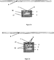
- One of preferred embodiments of the present invention for flat solar collectors (10) is within a standard confinement structure (15), the sides and in the back with opaque materials (5) and the top (1) with a transparent glass cover (1), with multi-layer insulation between the cover (1) and the absorber (4), which has two transparent insulation layers.
- the first layer, closest to the absorber (4), is monolithic type transparent silica aerogel (7), and the closest to the glass of the cover (1) is honeycomb-like transparent insulation material (2), as can be seen in Figure 2 , transparent separators (6) may be optionally included.
- this same collector (10) configuration may use granular transparent silica aerogel (7) instead of the monolithic type, confined within a glass layer or transparent polymer separator (6), such as polycarbonate or the like.
- the honeycomb transparent insulation layer (2) is located closer to the transparent glass cover (1), keeping the structure (2) at a lower temperature.
- each insulation layer (2, 7) will be determined according to final price-performance specifications. Due to the greater cost of transparent silica aerogel (7) compared to the honeycomb insulation structure (2), the later (2) will be thicker than silica (7) in common solar collectors (10), with the possibility of varying this to obtain greater performance. In this way, it is possible to obtain a wide range of flat solar collectors (10) with greater performance than currently existing ones and with variable production costs, only correcting the thickness of the layers (2, 7) without making great changes in the process or manufacturing machinery.
- an air or vacuum confinement space (16), consisting of an air (3) or vacuum (9) chamber is designed between the absorber (4) and the transparent silica aerogel layer (7), and/or between the transparent silica aerogel layer (7) and the honeycomb-shaped transparent insulation material (2). If the transparent silica aerogel (7) is of the granular type, the air or vacuum confinement space (16), consisting of an air (3) or vacuum (9) chamber, will be separated from the transparent silica aerogel (7) with a transparent separator (6) formed by a transparent material film or glass.
- the air or vacuum confinement space (16), consisting of an air (3) or vacuum (9) chamber, will be separated from the transparent insulation honeycomb structure material (2) by other transparent separator film (6) or glass, as can be seen in Figure 3 , thus protecting the transparent silica aerogel (7) and/or transparent honeycomb polymer (2) in case of stagnation of the heat-bearing fluid.
- the flat collector (10) type it is optionally possible to replace the opaque (5) rockwool type or similar insulation of the sides and back of the collector by any of the configurations of multi-layer transparent insulation described above.
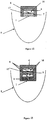
- FIG. 4 An example of this type of configuration can be seen in Figure 4 , where you can see a configuration composed of the silica aerogel insulation (7) surrounding the absorber (4) and these (4, 7) in turn surrounded by a polymer layer or transparent glass acting as a separator (6) and all confined by a glass or similar cover (1).
- the transparent glass cover (1) may be replaced by transparent polymer of similar characteristics to the transparent glass cover (1), which is ideal for working temperature of the flat solar collector (10).
- the embodiment consist of adding a layer of transparent insulation material of the granular or monolithic type silica aerogel (7) between the tube forming the transparent cover (1), made of glass, quartz or transparent polymeric material, and the absorber (4).
- FIG 6 is a simplified illustration of a cylindrical-parabolic concentration collector (11), in one of the most common embodiments of concentration collector (11) which includes, as discussed above, a transparent monolithic or granular silica aerogel layer (7) around the tubular absorber (4), which is confined in the glass or transparent polymeric material cover (1), in a tube shape.
- a transparent monolithic or granular silica aerogel layer (7) around the tubular absorber (4), which is confined in the glass or transparent polymeric material cover (1), in a tube shape.
- transparent silica aerogel (7) material is highly appropriate for these collectors (11), as they work at very high temperatures but typically lower than the resistance limit of the material (7). Therefore, it is possible to make more efficient collectors (11) by reducing thermal losses, and thus reducing production and maintenance costs in comparison to other technologies.
- the aforementioned preferred embodiment may include an air or vacuum confinement space (16), consisting of an air (3) or vacuum (9) chamber between the absorbent tubular surface (4) and the transparent silica aerogel insulating material (7) in order to protect this layer (7) from possible overheating in case of very high temperature applications.
- Figure 7 shows an example of a concentration collector (11), with a transparent silica aerogel layer (7) and the confinement space (16) between the absorber (4) and the silica aerogel (7).
- Figure 7 shows an additional layer of transparent honeycomb insulating material (2), confined between the glass cylinder, quartz or transparent polymeric material of the cover (1), and another cylinder separator (6) which separates it from a second more exterior confinement space (16).
- This additional layer of transparent honeycomb insulating material (2) may be optionally added so as to achieve good thermal insulation. In this way, with multi-layer insulation, one can use less transparent silica aerogel (7) in the more internal layer.
- a concentration collector (11) with a parabolic plate (8) as a concentrator member in which the absorber (4) does not receive the solar radiation from all sides, but which has a cylinder shape in which only the end points to or which the plate-parabolic (8) is pointed to, receives the solar radiation, the rest of the sides being insulated (17) with opaque (5) or transparent (7) coatings and confined within a rigid encapsulating element.
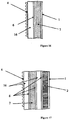
- the solar receiver conists of a multi-layer structure formed by a glass, transparent polymeric material or quartz cover (1), which closes the front and which is pointed to or to which the plate points (8), another transparent silica aerogel layer (7), followed this (7) by a transparent glass or quartz separator (6), an air or vacuum confinement space (16), consisting of an air (3) or vacuum (9) chamber and finally the absorber (4) (see Figure 8 ).
- the multi-layer structure may be improved with air chambers (3) and an additional transparent honeycomb material layer (2).
- the transparent multi-layer insulation is composed of a glass, polymeric material or transparent quartz cover (1) which closes the front, which is pointed to or to which the plate (8) points, another transparent honeycomb material layer (2), a transparent separator (6), an air or vacuum confinement space (16), consisting of an air (3) or vacuum (9) chamber, a transparent separator (6), another layer of transparent silica aerogel (7), followed this (7) by a separator (6) and an air or vacuum confinement space (16), consisting of an air (3) or vacuum (9) chamber and finally the absorber (4) (see Figure 9 ).
- the mentioned confinement space (16) is especially recommendable, consisting of an air (3) or vacuum (9) chamber for protecting the transparent silica aerogel (7) from excess temperature.
- the absorber (4) consists of a square or rectangular shaped selective reception surface, which transfers the energy to the heat-bearing fluid which flows through small section tubes or conduits, which may be only a few square millimetres to square nanometres and are in contact with the reception surface.
- the transparent insulation would consist of a glass, transparent polymeric material or quartz cover (1), which closes the front, pointing towards the concentrator member (8), another transparent silica aerogel layer (7), followed this (7) by a transparent glass or quartz separator (6) and an air or vacuum confinement space (16), consisting of an air (3) or vacuum (9) chamber and finally the absorber (4) (see Figure 10 ). All encapsulated in a structure thermally insulated on the sides with insulating material (17), which may be an opaque conventional insulation coating (5) or silica aerogel (7) coating.
- the absorber (4) also consists of a square or rectangular shaped selective reception surface, which transfers the energy to the heat-bearing fluid which flows through small section tubes or conduits, which may be only a few square millimetres to square nanometres and are in contact with the reception surface.
- the multi-layer transparent insulation consists of a glass, transparent polymeric material or quartz cover (1), which closes the front and points towards the concentrator member (8), another transparent honeycomb structure material layer (2), a glass, quartz or polymer layer forming a transparent separator (6), an air or vacuum confinement space (16), consisting of an air (3) or vacuum (9) chamber, a transparent separator layer (6), another transparent silica aerogel layer (7), followed this (7) by a transparent glass or quartz separator (6), and an air or vacuum confinement space (16), consisting of an air (3) or vacuum (9) chamber and finally the absorber (4) (see Figure 11 ). All also encapsulated in a structure thermally insulated on the sides with insulating material (17), which may be an opaque conventional insulation coating (5) or silica aerogel (7) coating.
- insulating material (17) which may be an opaque conventional insulation coating (5) or silica aerogel (7) coating.
- a variant of the last two preferred embodiments is a cylindrical-parabolic (8) or plate-parabolic concentrator (8) (see Figure 12 ).
- the structure of the square or rectangular shaped absorber (4) is also a selective reception surface, in contact-with small section tubes or conduits, from a few square millimetres to square nanometres, in contact-with the receptive surface, which transfers the heat energy to the heat-bearing fluid.
- the multi-layer insulation would consist of a glass, polymeric transparent material or transparent quartz cover (1) closing the front, which faces or the concentrator member or to which the concentrator member (8) faces, another transparent silica aerogel layer (7), followed this (7) by a transparent glass or quartz separator (6) and an air or vacuum confinement space (16), consisting of an air (3) or vacuum (9) chamber and finally the absorber (4) (see Figure 12 ). All encapsulated in a structure thermally insulated on the sides with insulating material (17), which may be an opaque conventional coating (5) or silica aerogel (7) coating.
- An alternative to the aforementioned preferred embodiment is a solar concentration collector (11) with a parabolic cylinder or parabolic plate as a concentrator member (8).
- the absorber (4) also consists of a square or rectangular shaped selective reception surface, which transfers the energy to the heat-bearing fluid which flows through small section tubes or conduits, which may be only a few square millimetres to square nanometres and are in contact with the reception surface.
- the transparent multi-layer insulation consists of a glass or transparent quartz cover (1), that closes the front, which points to the concentrator member or which the concentrator member (8) is faced, another honeycomb structure transparent material layer (2), a glass, quartz or transparent polymer separator layer (6), an air or vacuum confinement space (16), consisting of an air (3) or vacuum (9) chamber, a glass, quartz or transparent polymer separator layer (6), another transparent silica aerogel layer (7), followed this (7) by a transparent glass or quartz separator (6), another air or vacuum confinement space (16), consisting of an air (3) or vacuum (9) chamber and finally the absorber (4) (see Figure 13 ). All also encapsulated in a structure thermally insulated on the sides with insulating material (17), which may be an opaque conventional coating (5) or silica aerogel (7) coating.
- the transparent multi-layer insulation would consist of a glass, quartz or transparent polymeric material cover (1) closing the outside, which points to or to which the heliostats (8) are facing, another transparent silica aerogel layer (7), followed this (7) by a transparent glass or quartz separator (6) and an air or vacuum confinement space (16), consisting of an air (3) or vacuum (9) chamber and finally the absorber (4).
- the multi-layer transparent insulation consists of a glass, quartz or transparent polymeric material cover (1), which closes the front and points towards the heliostats (8), another transparent honeycomb structure material layer (2), a glass, quartz or polymer transparent separator layer (6), an air or vacuum confinement space (16), consisting of an air (3) or vacuum (9) chamber, a glass, quartz or transparent polymer separator layer (6), another transparent silica aerogel layer (7), followed this (7) by a transparent glass or quartz separator (6), an air or vacuum confinement space (16), consisting of an air (3) or vacuum (9) chamber, and and finally the absorber (4).
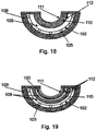
- the solar collector comprises one of the possible embodiments contemplated from outside to inside, an exterior coating (110) which follows the perimeter of said concave collector, covering an absorber (102), which has some tubes or passageways attached to it (105).
- the absorber (102) is surrounded by an air or vacuum confinement space (106).
- the confinement space (106) is covered with transparent silica aerogel (111), placing a transparent separator element (112) between the confinement space (106) and the silica aerogel (111), which has a transparent cover on its upper part (111).
- the solar collector comprises, from outside to inside, an exterior transparent insulating material coating (110), which follows the perimeter of said concave collector, and also that covers the upper part of the collector.
- the coating (110) is covered on its inside with the absorber (102), which has the channels attached to it (106).
- the absorber (102) is surrounded by an air or vacuum confinement space (106) with the transparent silica aerogel (111) placed above this space (106) and between these (106) and (111) is a separator element (112), and above the transparent silica aerogel (111) there is another separator element (112), covered by the honeycomb structure transparent insulation (100), and finally covering the insulation (100) there is a transparent cover (111).
Claims (10)
- CAPTEUR THERMIQUE SOLAIRE AVEC ISOLATION TRANSPARENTE, utilisé pour capturer l'énergie solaire et la transformer en énergie calorifique, fonctionnant à basse-moyenne ou haute température et constitué principalement d'un absorbeur (4), un couvercle transparent extérieur (1) et un matériau isolant thermique transparent entre le couvercle transparent extérieur (1) et l'absorbeur (4), caractérisé en ce que l'isolation thermique transparente comprend au moins les couches suivantes :- une couche d'aérogel de silice transparent (7) la plus proche de l'absorbeur (4) ; et- une couche de matériau d'isolation à structure alvéolaire transparente (2) constituée de verre ou de polymère transparent, la plus proche du couvercle (1).
- CAPTEUR THERMIQUE SOLAIRE AVEC ISOLATION TRANSPARENTE, selon la revendication 1, caractérisé en ce que le capteur thermique solaire est un capteur solaire plat (10).
- CAPTEUR THERMIQUE SOLAIRE AVEC ISOLATION TRANSPARENTE, selon la revendication 1, caractérisé en ce que le capteur thermique solaire est un capteur solaire à concentration (11).
- CAPTEUR THERMIQUE SOLAIRE AVEC ISOLATION TRANSPARENTE, selon les revendications précédentes, caractérisé en ce que, entre les deux couches d'isolation thermique transparentes, est placé un espace de confinement d'air ou de vide (16), constitué d'une chambre à air (3) ou à vide (9), séparé (16) du matériau d'isolation transparent (2) par un séparateur transparent (6), bien que la couche susmentionnée ne soit pas nécessaire si la couche d'aérogel de silice (7) est de type monolithique.
- CAPTEUR THERMIQUE SOLAIRE AVEC ISOLATION TRANSPARENTE, selon la revendication 1, caractérisé en ce que la structure alvéolaire de la couche constituée du matériau isolant susmentionné (2) comporte peu de matériau isolant de structure alvéolaire transparente, constitué de verre ou de polymère transparent avec une fraction en volume de matériau égale ou inférieure à 1%.
- CAPTEUR THERMIQUE SOLAIRE AVEC ISOLATION TRANSPARENTE, selon la revendication 3, caractérisé en ce que l'isolation thermique transparente est appliquée à la cavité de réception (14) d'une tour solaire (13).
- CAPTEUR THERMIQUE SOLAIRE AVEC ISOLATION TRANSPARENTE, selon les revendications précédentes 1, 4, 5 et 6, caractérisé en ce que les matériaux isolants thermiques, l'aérogel de silice transparent (7), le matériau d'isolation à structure alvéolaire transparente (2) et les espaces de confinement d'air ou de vide (16), sont d'une épaisseur suffisante pour éviter que chaque type de matériau n'atteigne la température maximale admissible de fonctionnement dans des conditions de stagnation, l'aérogel de silice transparent (7) résistant à des températures plus élevées que le matériau à structure alvéolaire transparent (2).
- CAPTEUR THERMIQUE SOLAIRE AVEC ISOLATION TRANSPARENTE, selon les revendications précédentes, caractérisé en ce que les côtés et l'arrière du capteur sont isolés avec des couches opaques (5), et que lesdites couches opaques peuvent être remplacées par des couches de matériau aérogel de silice (7).
- « CAPTEUR THERMIQUE SOLAIRE AVEC ISOLATION TRANSPARENTE », selon les revendications précédentes 1, 4 et 7, caractérisé en ce que le matériau de la couche d'aérogel de silice (7) peut être de l'aérogel de silice ou du xérogel de silice, tous deux transparents, et présentés sous forme granulaire ou monolithique.
- « CAPTEUR THERMIQUE SOLAIRE AVEC ISOLATION TRANSPARENTE », selon la revendication 9, caractérisé en ce que lorsque la couche d'isolation en aérogel de silice ou en xérogel de silice transparents (7) est sous forme granulaire, il y aura une ou plusieurs couches séparatrices au-dessus et/ou en dessous de ce (7) séparateur transparent (6).
Applications Claiming Priority (2)
| Application Number | Priority Date | Filing Date | Title |
|---|---|---|---|
| ES201130770A ES2431470B1 (es) | 2011-05-13 | 2011-05-13 | Captadores solares térmicos con aislamiento transparente |
| ES201230504A ES2447140B1 (es) | 2012-04-02 | 2012-04-02 | Captadores solares térmicos con aislamiento transparente, mejorados |
Publications (3)
| Publication Number | Publication Date |
|---|---|
| EP2522927A2 EP2522927A2 (fr) | 2012-11-14 |
| EP2522927A3 EP2522927A3 (fr) | 2013-01-23 |
| EP2522927B1 true EP2522927B1 (fr) | 2017-12-27 |
Family
ID=46262060
Family Applications (1)
| Application Number | Title | Priority Date | Filing Date |
|---|---|---|---|
| EP12382173.8A Active EP2522927B1 (fr) | 2011-05-13 | 2012-05-10 | Collecteur solaire thermique avec isolation transparente |
Country Status (1)
| Country | Link |
|---|---|
| EP (1) | EP2522927B1 (fr) |
Cited By (1)
| Publication number | Priority date | Publication date | Assignee | Title |
|---|---|---|---|---|
| US11170750B2 (en) | 2018-04-25 | 2021-11-09 | Massachusetts Institute Of Technology | Energy efficient soundproofing window retrofits |
Families Citing this family (13)
| Publication number | Priority date | Publication date | Assignee | Title |
|---|---|---|---|---|
| JP5368227B2 (ja) * | 2009-09-16 | 2013-12-18 | 大和ハウス工業株式会社 | 太陽熱集熱構造 |
| ES2424830B1 (es) * | 2012-03-02 | 2014-07-30 | Universitat Politècnica De Catalunya | Captador solar con aislamiento transparente plástico y protección al sobrecalentamiento |
| KR101464869B1 (ko) * | 2013-03-29 | 2014-11-24 | 주식회사엑스엘 | 태양열 진공집열패널 및 이를 이용한 태양열 집열모듈 |
| CN105229390B (zh) * | 2013-04-12 | 2018-02-16 | 桑普雷特公司 | 包括不透明盖的太阳能收集器 |
| DE102014210674A1 (de) * | 2014-06-05 | 2015-12-17 | Robert Bosch Gmbh | Verfahren zum Herstellen eines Solarkollektors |
| WO2015193870A2 (fr) * | 2014-06-19 | 2015-12-23 | Lakshmanan Karthigueyane | Concentrateur parabolique à deux étages |
| BR112017009355A2 (pt) | 2014-11-25 | 2017-12-19 | Sabic Global Technologies Bv | coletor solar, método para produzir um coletor solar térmico |
| FR3037981B1 (fr) * | 2015-06-23 | 2018-12-14 | Commissariat A L'energie Atomique Et Aux Energies Alternatives | Procede de pose d'un parement exterieur sur une facade d'un batiment et batiment correspondant |
| WO2016210339A1 (fr) * | 2015-06-25 | 2016-12-29 | Nitto Denko Corporation | Élément de chauffe-eau solaire |
| US10889501B2 (en) | 2016-02-24 | 2021-01-12 | Massachusetts Institute Of Technology | Solar thermal aerogel receiver and materials therefor |
| FR3054647B1 (fr) * | 2016-08-01 | 2019-06-07 | Saint-Gobain Isover | Isolation de collecteur solaire et produit obtenu |
| CN112629044B (zh) * | 2020-12-31 | 2022-07-22 | 广西赫阳能源科技有限公司 | 一种太阳能中高温热水器 |
| CN115108561A (zh) * | 2022-07-25 | 2022-09-27 | 山东大学 | 一种用于聚光光热电站的透明隔热气凝胶结构及制备方法 |
Family Cites Families (13)
| Publication number | Priority date | Publication date | Assignee | Title |
|---|---|---|---|---|
| US4038964A (en) | 1975-07-25 | 1977-08-02 | Drew George F | Parabolic solar concentrator employing flat plate collector |
| DE2937529C2 (de) | 1979-09-17 | 1983-05-11 | Kraftwerk Union AG, 4330 Mülheim | Sonnenkraftwerk |
| US4432346A (en) | 1979-10-17 | 1984-02-21 | Westerstrandh Bjoern V | Solar collector |
| DE3706196A1 (de) * | 1987-02-26 | 1988-09-29 | Fraunhofer Ges Forschung | Warmwasserbereiter in form eines solarkollektors |
| DE3923821A1 (de) * | 1989-07-19 | 1991-01-24 | Otto Dipl Phys Spormann | Kollektor zur gewinnung von energie aus der strahlung der sonne |
| EP0473859A1 (fr) * | 1990-08-27 | 1992-03-11 | Günther Seidel | Mur pour l'absorption du rayonnement et méthode pour l'absorption du rayonnement et le transfert d'énergie thermique dans les murs solaires |
| US5182912A (en) | 1991-03-12 | 1993-02-02 | Solar Reactor Technologies, Inc. | Fluid absorption receiver for solar radiation |
| US5524381A (en) * | 1991-03-19 | 1996-06-11 | Chahroudi; Day | Solar heated building designs for cloudy winters |
| DE4400917A1 (de) * | 1994-01-14 | 1995-07-20 | Friedrich Becker | Wärmepumpender Solarkollektor |
| AUPO987697A0 (en) * | 1997-10-17 | 1997-11-13 | Gough Industries Pty Ltd | Solar water heater |
| ES2273534B1 (es) | 2004-04-06 | 2008-04-16 | Itelsa, S.L. | Cubierta aislante transparente para aplicaciones solares termicas. |
| DE102006022426A1 (de) * | 2006-05-13 | 2007-11-15 | Friedrich Becker | Luftbetriebener Solarkollektor mit transparenter Wärmedämmung, integriertem Heißluftmotor und Wärmepumpe |
| JP2011033276A (ja) * | 2009-07-31 | 2011-02-17 | Daiwa House Industry Co Ltd | 太陽熱集熱構造 |
-
2012
- 2012-05-10 EP EP12382173.8A patent/EP2522927B1/fr active Active
Non-Patent Citations (1)
| Title |
|---|
| None * |
Cited By (2)
| Publication number | Priority date | Publication date | Assignee | Title |
|---|---|---|---|---|
| US11170750B2 (en) | 2018-04-25 | 2021-11-09 | Massachusetts Institute Of Technology | Energy efficient soundproofing window retrofits |
| US11749247B2 (en) | 2018-04-25 | 2023-09-05 | Massachusetts Institute Of Technology | Energy efficient soundproofing window retrofits |
Also Published As
| Publication number | Publication date |
|---|---|
| EP2522927A2 (fr) | 2012-11-14 |
| EP2522927A3 (fr) | 2013-01-23 |
Similar Documents
| Publication | Publication Date | Title |
|---|---|---|
| EP2522927B1 (fr) | Collecteur solaire thermique avec isolation transparente | |
| US11435506B2 (en) | Thin-film integrated spectrally-selective plasmonic absorber/emitter for solar thermophotovoltaic applications | |
| US6384320B1 (en) | Solar compound concentrator of electric power generation system for residential homes | |
| AU2003259804A1 (en) | Concentrating solar energy receiver | |
| US20140026944A1 (en) | Absorber tube for a trough collector | |
| EP3152782B1 (fr) | Concentrateur parabolique à deux étages | |
| Norton | Anatomy of a solar collector: developments in materials, components and efficiency improvements in solar thermal collector systems | |
| US10931227B2 (en) | Light-heat energy gathering solar energy device | |
| KR102168493B1 (ko) | 태양광열 발전용 패널 | |
| Morciano et al. | Installation of a concentrated solar power system for the thermal needs of buildings or industrial processes | |
| WO2011101485A1 (fr) | Tube capteur de chaleur solaire pour génération directe de vapeur, réflecteur cylindro-parabolique muni du tube capteur de chaleur solaire et utilisation du réflecteur cylindro-parabolique | |
| CN101893325A (zh) | 聚光型高效平板复合集热器 | |
| KR101568927B1 (ko) | 태양열을 이용한 고집광 셀 구조 | |
| JPS61165702A (ja) | 太陽光発電装置 | |
| CN101846402A (zh) | 菲涅尔太阳集热器 | |
| WO2012176007A1 (fr) | Capteur solaire | |
| CN101592403A (zh) | 大型、高效、相对低成本槽式太阳能锅炉系统 | |
| KR101966213B1 (ko) | 태양열 흡수효율증가용 표면코팅을 갖는 pv모듈 및 집열모듈 복합 시스템 | |
| JP2003322419A (ja) | 住宅用電力発電システムの太陽光複合集束機 | |
| CN202149632U (zh) | 一种槽式太阳能集热管 | |
| RU2430311C2 (ru) | Абсорбер параболоцилиндрического концентратора солнечной энергии с системой слежения за солнцем | |
| US20170040930A1 (en) | Finned passive pvt system with adjustable angle insulating reflectors | |
| US20230402970A1 (en) | Thermal contact sheet for photovoltaic thermal collector | |
| KR20020047766A (ko) | 투명 단열재를 이용한 평판형 태양열 집열기 | |
| RU90884U1 (ru) | Солнечный коллектор |
Legal Events
| Date | Code | Title | Description |
|---|---|---|---|
| PUAI | Public reference made under article 153(3) epc to a published international application that has entered the european phase |
Free format text: ORIGINAL CODE: 0009012 |
|
| 17P | Request for examination filed |
Effective date: 20120511 |
|
| AK | Designated contracting states |
Kind code of ref document: A2 Designated state(s): AL AT BE BG CH CY CZ DE DK EE ES FI FR GB GR HR HU IE IS IT LI LT LU LV MC MK MT NL NO PL PT RO RS SE SI SK SM TR |
|
| AX | Request for extension of the european patent |
Extension state: BA ME |
|
| PUAL | Search report despatched |
Free format text: ORIGINAL CODE: 0009013 |
|
| AK | Designated contracting states |
Kind code of ref document: A3 Designated state(s): AL AT BE BG CH CY CZ DE DK EE ES FI FR GB GR HR HU IE IS IT LI LT LU LV MC MK MT NL NO PL PT RO RS SE SI SK SM TR |
|
| AX | Request for extension of the european patent |
Extension state: BA ME |
|
| RIC1 | Information provided on ipc code assigned before grant |
Ipc: F24J 2/26 20060101ALI20121214BHEP Ipc: F24J 2/07 20060101ALI20121214BHEP Ipc: F24J 2/50 20060101ALI20121214BHEP Ipc: F24J 2/05 20060101AFI20121214BHEP Ipc: F24J 2/51 20060101ALI20121214BHEP Ipc: F24J 2/12 20060101ALI20121214BHEP Ipc: F24J 2/04 20060101ALI20121214BHEP Ipc: F24J 2/10 20060101ALI20121214BHEP Ipc: F24J 2/14 20060101ALI20121214BHEP Ipc: F24J 2/16 20060101ALI20121214BHEP |
|
| 17Q | First examination report despatched |
Effective date: 20160922 |
|
| STAA | Information on the status of an ep patent application or granted ep patent |
Free format text: STATUS: EXAMINATION IS IN PROGRESS |
|
| RIC1 | Information provided on ipc code assigned before grant |
Ipc: F24J 2/50 20060101ALI20170531BHEP Ipc: F24J 2/12 20060101ALI20170531BHEP Ipc: F24J 2/10 20060101ALI20170531BHEP Ipc: F24J 2/24 20060101ALI20170531BHEP Ipc: F24J 2/07 20060101ALI20170531BHEP Ipc: F24J 2/16 20060101ALI20170531BHEP Ipc: F24J 2/51 20060101ALI20170531BHEP Ipc: F24J 2/05 20060101AFI20170531BHEP Ipc: F24J 2/26 20060101ALI20170531BHEP Ipc: F24J 2/14 20060101ALI20170531BHEP Ipc: F24J 2/04 20060101ALI20170531BHEP |
|
| GRAP | Despatch of communication of intention to grant a patent |
Free format text: ORIGINAL CODE: EPIDOSNIGR1 |
|
| STAA | Information on the status of an ep patent application or granted ep patent |
Free format text: STATUS: GRANT OF PATENT IS INTENDED |
|
| INTG | Intention to grant announced |
Effective date: 20170725 |
|
| GRAA | (expected) grant |
Free format text: ORIGINAL CODE: 0009210 |
|
| GRAS | Grant fee paid |
Free format text: ORIGINAL CODE: EPIDOSNIGR3 |
|
| STAA | Information on the status of an ep patent application or granted ep patent |
Free format text: STATUS: THE PATENT HAS BEEN GRANTED |
|
| AK | Designated contracting states |
Kind code of ref document: B1 Designated state(s): AL AT BE BG CH CY CZ DE DK EE ES FI FR GB GR HR HU IE IS IT LI LT LU LV MC MK MT NL NO PL PT RO RS SE SI SK SM TR |
|
| REG | Reference to a national code |
Ref country code: GB Ref legal event code: FG4D |
|
| REG | Reference to a national code |
Ref country code: CH Ref legal event code: EP |
|
| REG | Reference to a national code |
Ref country code: AT Ref legal event code: REF Ref document number: 958635 Country of ref document: AT Kind code of ref document: T Effective date: 20180115 |
|
| REG | Reference to a national code |
Ref country code: IE Ref legal event code: FG4D |
|
| REG | Reference to a national code |
Ref country code: DE Ref legal event code: R096 Ref document number: 602012041308 Country of ref document: DE |
|
| REG | Reference to a national code |
Ref country code: FR Ref legal event code: PLFP Year of fee payment: 7 |
|
| PG25 | Lapsed in a contracting state [announced via postgrant information from national office to epo] |
Ref country code: NO Free format text: LAPSE BECAUSE OF FAILURE TO SUBMIT A TRANSLATION OF THE DESCRIPTION OR TO PAY THE FEE WITHIN THE PRESCRIBED TIME-LIMIT Effective date: 20180327 Ref country code: LT Free format text: LAPSE BECAUSE OF FAILURE TO SUBMIT A TRANSLATION OF THE DESCRIPTION OR TO PAY THE FEE WITHIN THE PRESCRIBED TIME-LIMIT Effective date: 20171227 Ref country code: FI Free format text: LAPSE BECAUSE OF FAILURE TO SUBMIT A TRANSLATION OF THE DESCRIPTION OR TO PAY THE FEE WITHIN THE PRESCRIBED TIME-LIMIT Effective date: 20171227 |
|
| REG | Reference to a national code |
Ref country code: NL Ref legal event code: MP Effective date: 20171227 |
|
| REG | Reference to a national code |
Ref country code: LT Ref legal event code: MG4D |
|
| REG | Reference to a national code |
Ref country code: AT Ref legal event code: MK05 Ref document number: 958635 Country of ref document: AT Kind code of ref document: T Effective date: 20171227 |
|
| PG25 | Lapsed in a contracting state [announced via postgrant information from national office to epo] |
Ref country code: RS Free format text: LAPSE BECAUSE OF FAILURE TO SUBMIT A TRANSLATION OF THE DESCRIPTION OR TO PAY THE FEE WITHIN THE PRESCRIBED TIME-LIMIT Effective date: 20171227 Ref country code: HR Free format text: LAPSE BECAUSE OF FAILURE TO SUBMIT A TRANSLATION OF THE DESCRIPTION OR TO PAY THE FEE WITHIN THE PRESCRIBED TIME-LIMIT Effective date: 20171227 Ref country code: BG Free format text: LAPSE BECAUSE OF FAILURE TO SUBMIT A TRANSLATION OF THE DESCRIPTION OR TO PAY THE FEE WITHIN THE PRESCRIBED TIME-LIMIT Effective date: 20180327 Ref country code: LV Free format text: LAPSE BECAUSE OF FAILURE TO SUBMIT A TRANSLATION OF THE DESCRIPTION OR TO PAY THE FEE WITHIN THE PRESCRIBED TIME-LIMIT Effective date: 20171227 Ref country code: GR Free format text: LAPSE BECAUSE OF FAILURE TO SUBMIT A TRANSLATION OF THE DESCRIPTION OR TO PAY THE FEE WITHIN THE PRESCRIBED TIME-LIMIT Effective date: 20180328 |
|
| PG25 | Lapsed in a contracting state [announced via postgrant information from national office to epo] |
Ref country code: NL Free format text: LAPSE BECAUSE OF FAILURE TO SUBMIT A TRANSLATION OF THE DESCRIPTION OR TO PAY THE FEE WITHIN THE PRESCRIBED TIME-LIMIT Effective date: 20171227 |
|
| PG25 | Lapsed in a contracting state [announced via postgrant information from national office to epo] |
Ref country code: EE Free format text: LAPSE BECAUSE OF FAILURE TO SUBMIT A TRANSLATION OF THE DESCRIPTION OR TO PAY THE FEE WITHIN THE PRESCRIBED TIME-LIMIT Effective date: 20171227 Ref country code: SK Free format text: LAPSE BECAUSE OF FAILURE TO SUBMIT A TRANSLATION OF THE DESCRIPTION OR TO PAY THE FEE WITHIN THE PRESCRIBED TIME-LIMIT Effective date: 20171227 Ref country code: CZ Free format text: LAPSE BECAUSE OF FAILURE TO SUBMIT A TRANSLATION OF THE DESCRIPTION OR TO PAY THE FEE WITHIN THE PRESCRIBED TIME-LIMIT Effective date: 20171227 Ref country code: ES Free format text: LAPSE BECAUSE OF FAILURE TO SUBMIT A TRANSLATION OF THE DESCRIPTION OR TO PAY THE FEE WITHIN THE PRESCRIBED TIME-LIMIT Effective date: 20171227 Ref country code: CY Free format text: LAPSE BECAUSE OF FAILURE TO SUBMIT A TRANSLATION OF THE DESCRIPTION OR TO PAY THE FEE WITHIN THE PRESCRIBED TIME-LIMIT Effective date: 20171227 |
|
| PG25 | Lapsed in a contracting state [announced via postgrant information from national office to epo] |
Ref country code: AT Free format text: LAPSE BECAUSE OF FAILURE TO SUBMIT A TRANSLATION OF THE DESCRIPTION OR TO PAY THE FEE WITHIN THE PRESCRIBED TIME-LIMIT Effective date: 20171227 Ref country code: PL Free format text: LAPSE BECAUSE OF FAILURE TO SUBMIT A TRANSLATION OF THE DESCRIPTION OR TO PAY THE FEE WITHIN THE PRESCRIBED TIME-LIMIT Effective date: 20171227 Ref country code: IT Free format text: LAPSE BECAUSE OF FAILURE TO SUBMIT A TRANSLATION OF THE DESCRIPTION OR TO PAY THE FEE WITHIN THE PRESCRIBED TIME-LIMIT Effective date: 20171227 Ref country code: RO Free format text: LAPSE BECAUSE OF FAILURE TO SUBMIT A TRANSLATION OF THE DESCRIPTION OR TO PAY THE FEE WITHIN THE PRESCRIBED TIME-LIMIT Effective date: 20171227 Ref country code: SM Free format text: LAPSE BECAUSE OF FAILURE TO SUBMIT A TRANSLATION OF THE DESCRIPTION OR TO PAY THE FEE WITHIN THE PRESCRIBED TIME-LIMIT Effective date: 20171227 Ref country code: IS Free format text: LAPSE BECAUSE OF FAILURE TO SUBMIT A TRANSLATION OF THE DESCRIPTION OR TO PAY THE FEE WITHIN THE PRESCRIBED TIME-LIMIT Effective date: 20180427 |
|
| REG | Reference to a national code |
Ref country code: DE Ref legal event code: R097 Ref document number: 602012041308 Country of ref document: DE |
|
| PLBE | No opposition filed within time limit |
Free format text: ORIGINAL CODE: 0009261 |
|
| STAA | Information on the status of an ep patent application or granted ep patent |
Free format text: STATUS: NO OPPOSITION FILED WITHIN TIME LIMIT |
|
| PG25 | Lapsed in a contracting state [announced via postgrant information from national office to epo] |
Ref country code: DK Free format text: LAPSE BECAUSE OF FAILURE TO SUBMIT A TRANSLATION OF THE DESCRIPTION OR TO PAY THE FEE WITHIN THE PRESCRIBED TIME-LIMIT Effective date: 20171227 |
|
| 26N | No opposition filed |
Effective date: 20180928 |
|
| REG | Reference to a national code |
Ref country code: CH Ref legal event code: PL |
|
| REG | Reference to a national code |
Ref country code: BE Ref legal event code: MM Effective date: 20180531 |
|
| PG25 | Lapsed in a contracting state [announced via postgrant information from national office to epo] |
Ref country code: MC Free format text: LAPSE BECAUSE OF FAILURE TO SUBMIT A TRANSLATION OF THE DESCRIPTION OR TO PAY THE FEE WITHIN THE PRESCRIBED TIME-LIMIT Effective date: 20171227 |
|
| REG | Reference to a national code |
Ref country code: IE Ref legal event code: MM4A |
|
| PG25 | Lapsed in a contracting state [announced via postgrant information from national office to epo] |
Ref country code: SI Free format text: LAPSE BECAUSE OF FAILURE TO SUBMIT A TRANSLATION OF THE DESCRIPTION OR TO PAY THE FEE WITHIN THE PRESCRIBED TIME-LIMIT Effective date: 20171227 Ref country code: LI Free format text: LAPSE BECAUSE OF NON-PAYMENT OF DUE FEES Effective date: 20180531 Ref country code: CH Free format text: LAPSE BECAUSE OF NON-PAYMENT OF DUE FEES Effective date: 20180531 |
|
| PG25 | Lapsed in a contracting state [announced via postgrant information from national office to epo] |
Ref country code: LU Free format text: LAPSE BECAUSE OF NON-PAYMENT OF DUE FEES Effective date: 20180510 |
|
| PG25 | Lapsed in a contracting state [announced via postgrant information from national office to epo] |
Ref country code: IE Free format text: LAPSE BECAUSE OF NON-PAYMENT OF DUE FEES Effective date: 20180510 |
|
| PG25 | Lapsed in a contracting state [announced via postgrant information from national office to epo] |
Ref country code: BE Free format text: LAPSE BECAUSE OF NON-PAYMENT OF DUE FEES Effective date: 20180531 |
|
| PG25 | Lapsed in a contracting state [announced via postgrant information from national office to epo] |
Ref country code: MT Free format text: LAPSE BECAUSE OF NON-PAYMENT OF DUE FEES Effective date: 20180510 |
|
| PG25 | Lapsed in a contracting state [announced via postgrant information from national office to epo] |
Ref country code: TR Free format text: LAPSE BECAUSE OF FAILURE TO SUBMIT A TRANSLATION OF THE DESCRIPTION OR TO PAY THE FEE WITHIN THE PRESCRIBED TIME-LIMIT Effective date: 20171227 |
|
| PG25 | Lapsed in a contracting state [announced via postgrant information from national office to epo] |
Ref country code: HU Free format text: LAPSE BECAUSE OF FAILURE TO SUBMIT A TRANSLATION OF THE DESCRIPTION OR TO PAY THE FEE WITHIN THE PRESCRIBED TIME-LIMIT; INVALID AB INITIO Effective date: 20120510 Ref country code: PT Free format text: LAPSE BECAUSE OF FAILURE TO SUBMIT A TRANSLATION OF THE DESCRIPTION OR TO PAY THE FEE WITHIN THE PRESCRIBED TIME-LIMIT Effective date: 20171227 |
|
| PG25 | Lapsed in a contracting state [announced via postgrant information from national office to epo] |
Ref country code: SE Free format text: LAPSE BECAUSE OF FAILURE TO SUBMIT A TRANSLATION OF THE DESCRIPTION OR TO PAY THE FEE WITHIN THE PRESCRIBED TIME-LIMIT Effective date: 20171227 Ref country code: MK Free format text: LAPSE BECAUSE OF NON-PAYMENT OF DUE FEES Effective date: 20171227 |
|
| PG25 | Lapsed in a contracting state [announced via postgrant information from national office to epo] |
Ref country code: AL Free format text: LAPSE BECAUSE OF FAILURE TO SUBMIT A TRANSLATION OF THE DESCRIPTION OR TO PAY THE FEE WITHIN THE PRESCRIBED TIME-LIMIT Effective date: 20171227 |
|
| PGFP | Annual fee paid to national office [announced via postgrant information from national office to epo] |
Ref country code: FR Payment date: 20200414 Year of fee payment: 9 |
|
| PGFP | Annual fee paid to national office [announced via postgrant information from national office to epo] |
Ref country code: GB Payment date: 20200429 Year of fee payment: 9 |
|
| GBPC | Gb: european patent ceased through non-payment of renewal fee |
Effective date: 20210510 |
|
| PG25 | Lapsed in a contracting state [announced via postgrant information from national office to epo] |
Ref country code: GB Free format text: LAPSE BECAUSE OF NON-PAYMENT OF DUE FEES Effective date: 20210510 |
|
| PG25 | Lapsed in a contracting state [announced via postgrant information from national office to epo] |
Ref country code: FR Free format text: LAPSE BECAUSE OF NON-PAYMENT OF DUE FEES Effective date: 20210531 |
|
| PGFP | Annual fee paid to national office [announced via postgrant information from national office to epo] |
Ref country code: DE Payment date: 20230516 Year of fee payment: 12 |