EP2522908A1 - Control method for controlling the pilot gas supply to at least one burner assembly of a gas turbine plant and gas turbine plant - Google Patents
Control method for controlling the pilot gas supply to at least one burner assembly of a gas turbine plant and gas turbine plant Download PDFInfo
- Publication number
- EP2522908A1 EP2522908A1 EP12167575A EP12167575A EP2522908A1 EP 2522908 A1 EP2522908 A1 EP 2522908A1 EP 12167575 A EP12167575 A EP 12167575A EP 12167575 A EP12167575 A EP 12167575A EP 2522908 A1 EP2522908 A1 EP 2522908A1
- Authority
- EP
- European Patent Office
- Prior art keywords
- flow rate
- basis
- pilot gas
- pilot
- igv
- Prior art date
- Legal status (The legal status is an assumption and is not a legal conclusion. Google has not performed a legal analysis and makes no representation as to the accuracy of the status listed.)
- Granted
Links
Images

Classifications
-
- F—MECHANICAL ENGINEERING; LIGHTING; HEATING; WEAPONS; BLASTING
- F23—COMBUSTION APPARATUS; COMBUSTION PROCESSES
- F23N—REGULATING OR CONTROLLING COMBUSTION
- F23N1/00—Regulating fuel supply
- F23N1/02—Regulating fuel supply conjointly with air supply
- F23N1/022—Regulating fuel supply conjointly with air supply using electronic means
-
- F—MECHANICAL ENGINEERING; LIGHTING; HEATING; WEAPONS; BLASTING
- F02—COMBUSTION ENGINES; HOT-GAS OR COMBUSTION-PRODUCT ENGINE PLANTS
- F02C—GAS-TURBINE PLANTS; AIR INTAKES FOR JET-PROPULSION PLANTS; CONTROLLING FUEL SUPPLY IN AIR-BREATHING JET-PROPULSION PLANTS
- F02C9/00—Controlling gas-turbine plants; Controlling fuel supply in air- breathing jet-propulsion plants
- F02C9/26—Control of fuel supply
- F02C9/263—Control of fuel supply by means of fuel metering valves
-
- F—MECHANICAL ENGINEERING; LIGHTING; HEATING; WEAPONS; BLASTING
- F02—COMBUSTION ENGINES; HOT-GAS OR COMBUSTION-PRODUCT ENGINE PLANTS
- F02C—GAS-TURBINE PLANTS; AIR INTAKES FOR JET-PROPULSION PLANTS; CONTROLLING FUEL SUPPLY IN AIR-BREATHING JET-PROPULSION PLANTS
- F02C9/00—Controlling gas-turbine plants; Controlling fuel supply in air- breathing jet-propulsion plants
- F02C9/26—Control of fuel supply
- F02C9/28—Regulating systems responsive to plant or ambient parameters, e.g. temperature, pressure, rotor speed
-
- F—MECHANICAL ENGINEERING; LIGHTING; HEATING; WEAPONS; BLASTING
- F23—COMBUSTION APPARATUS; COMBUSTION PROCESSES
- F23N—REGULATING OR CONTROLLING COMBUSTION
- F23N5/00—Systems for controlling combustion
- F23N5/18—Systems for controlling combustion using detectors sensitive to rate of flow of air or fuel
- F23N5/184—Systems for controlling combustion using detectors sensitive to rate of flow of air or fuel using electronic means
-
- F—MECHANICAL ENGINEERING; LIGHTING; HEATING; WEAPONS; BLASTING
- F23—COMBUSTION APPARATUS; COMBUSTION PROCESSES
- F23R—GENERATING COMBUSTION PRODUCTS OF HIGH PRESSURE OR HIGH VELOCITY, e.g. GAS-TURBINE COMBUSTION CHAMBERS
- F23R3/00—Continuous combustion chambers using liquid or gaseous fuel
- F23R3/28—Continuous combustion chambers using liquid or gaseous fuel characterised by the fuel supply
- F23R3/34—Feeding into different combustion zones
- F23R3/343—Pilot flames, i.e. fuel nozzles or injectors using only a very small proportion of the total fuel to insure continuous combustion
-
- F—MECHANICAL ENGINEERING; LIGHTING; HEATING; WEAPONS; BLASTING
- F23—COMBUSTION APPARATUS; COMBUSTION PROCESSES
- F23N—REGULATING OR CONTROLLING COMBUSTION
- F23N1/00—Regulating fuel supply
- F23N1/02—Regulating fuel supply conjointly with air supply
-
- F—MECHANICAL ENGINEERING; LIGHTING; HEATING; WEAPONS; BLASTING
- F23—COMBUSTION APPARATUS; COMBUSTION PROCESSES
- F23N—REGULATING OR CONTROLLING COMBUSTION
- F23N5/00—Systems for controlling combustion
- F23N5/18—Systems for controlling combustion using detectors sensitive to rate of flow of air or fuel
- F23N2005/185—Systems for controlling combustion using detectors sensitive to rate of flow of air or fuel using detectors sensitive to rate of flow of fuel
-
- F—MECHANICAL ENGINEERING; LIGHTING; HEATING; WEAPONS; BLASTING
- F23—COMBUSTION APPARATUS; COMBUSTION PROCESSES
- F23N—REGULATING OR CONTROLLING COMBUSTION
- F23N2235/00—Valves, nozzles or pumps
- F23N2235/02—Air or combustion gas valves or dampers
- F23N2235/06—Air or combustion gas valves or dampers at the air intake
-
- F—MECHANICAL ENGINEERING; LIGHTING; HEATING; WEAPONS; BLASTING
- F23—COMBUSTION APPARATUS; COMBUSTION PROCESSES
- F23N—REGULATING OR CONTROLLING COMBUSTION
- F23N2241/00—Applications
- F23N2241/20—Gas turbines
Definitions
- the present invention relates to a control method for controlling the pilot gas supply to at least one burner assembly of a gas turbine plant, and to a gas turbine plant.
- Gas turbine plants of known type comprise an annular combustion chamber provided with a plurality of burner assemblies. Each burner assembly is provided with a main premixing burner, commonly referred to as premix burner, and with a pilot burner.
- premix burner a main premixing burner
- pilot burner a pilot burner
- Any plant connected to an electricity network except for windpower and photovoltaic plants, must adjust the power input (also referred to as load) to comply with the mains frequency (50Hz in Europe, 60Hz in the USA).
- Mains frequency variations are an indicator of the balance between electric energy production and consumption: if the mains frequency decreases, it means that the energy consumption exceeds production; in contrast, if the mains frequency increases, the energy production exceeds consumption.
- plants In order to avoid undesired oscillations in the mains frequency, plants must respond to variations in power requirement (commonly referred to as primary requirement) by the mains in well-defined times. Moreover, the primary requirement adds up to the ordinary internal power variation requirements comprising plant requirements and small power variations (in the range of few MW), unavoidably due to the combustion and control process physics.
- Plants of known type are not always capable of obtaining power variations within the required times. Recently, in fact, power variations in the range of as much as 36 MW/min have been required and it often happens that the plants are not capable of meeting this type of requirements.
- the present invention relates to a control method for controlling the pilot gas supply to at least one burner assembly of a gas turbine plant, and to a gas turbine plant according to claims 1 and 9, respectively.
- reference numeral 1 indicates a gas turbine plant for producing electric energy.
- Plant 1 comprises a compressor 3, a combustion chamber 4, a gas turbine 6 and a generator 7, which transforms the mechanical power supplied by turbine 6 into electric power P EL to be supplied to an electricity network 8 connected to generator 7 by a switch 9.
- Compressor 3 is provided with an inlet stage 10 having a varying geometry.
- the inlet stage 10 comprises a plurality of adjustable inlet stator vanes 11 (diagrammatically shown in figure 1 ), commonly referred to as IGV (Inlet Guide Vane), the position IGVPOS of which may be changed to adjust an air flow rate drawn by the compressor 3 itself.
- IGV Inlet Guide Vane
- the combustion chamber 4 is preferably of the annular type and comprises a plurality of burner assemblies 15, a gas supply circuit 16 configured to supply the burner assemblies 15, and a control device 17 to control the gas supply to at least one burner assembly 15.
- the burner assemblies 15 are arranged along a circular path close to an annular peripheral edge 18 of the combustion chamber 4 and face the interior of the combustion chamber 4.
- Each burner assembly 15 extends along an axis and comprises a main peripheral burner (not shown for simplicity) and a central pilot burner 20 (diagrammatically shown in figure 1 ).
- the main burner is of the premix type and is preferably arranged around the pilot burner 20.
- the gas supply circuit 16 comprises a premix supply line (not shown for simplicity), configured to supply the main burners, and a pilot supply line 21, configured to supply the pilot burners 20.
- the pilot supply line 21 comprises a control valve 22 and a manifold 23 connected to the pilot burners 20 of each burner assembly 15.
- the opening degree of the control valve 22 is adjusted by the control device 17 for controlling the pilot gas supply to at least one burner assembly 15 according to the present invention.
- control device 17 is configured to adjust the opening of the control valve 22.
- the control device 17 comprises a first calculation module 25 configured to calculate a pilot gas basis flow rate Q P , a second calculation module 28 configured to calculate a pilot gas flow rate variation ⁇ Q P , an adder node 29 configured to provide the sum of the pilot gas basis flow rate Q P and the pilot gas flow rate variation ⁇ Q P , and a valve control module 30, which is configured to control the opening of the control valve 22 on the basis of the sum of the pilot gas basis flow rate Q P and the pilot gas flow rate variation ⁇ Q P .
- the second calculation module 28 is configured to calculate a pilot gas flow rate variation ⁇ Q P on the basis of the position IGV POS of the adjustable inlet stator vanes 11 and to the electric power P EL supplied by generator 7.
- the calculation module 28 comprises a calculation block 35 configured to calculate a pilot gas flow rate variation ⁇ QP grad , a correction calculation block 36 configured to calculate a correction coefficient K IGV for correcting the pilot gas flow rate variation ⁇ Q Pgrad on the basis of the position IGV POS , a multiplier node 37 and a limiter block 38.
- the calculation block 35 is configured to calculate the pilot gas flow rate variation ⁇ Q Pgrad on the basis of the electric power P EL supplied by generator 7; in particular, the calculation block 35 is configured to calculate the pilot gas flow rate variation ⁇ Q Pgrad on the basis of the electric power gradient GRAD.
- electric power gradient GRAD means the variation ⁇ P EL in the electric power supplied by generator 7 in the time unit.
- the calculation block 35 comprises a gradient module 40, a flow rate module 41 and an activation module 42.
- the gradient module 40 is configured to calculate the electric power gradient GRAD.
- the gradient module 40 comprises a calculation module MV 43 configured to calculate a fast average MV of the input signal P EL , a calculation module ML 44 configured to calculate a slow average ML of the input signal P EL, a subtractor node 45 and a conversion module 46.
- calculation module MV 43 and the calculation module ML 44 are configured to calculate a respective moving average of the input electric power signal P EL considering different time intervals.
- the calculation module MV 43 is configured to calculate the fast average MV as a moving average in a time interval of a magnitude order of tenths of seconds.
- the power oscillations P EL considered as "noise" are substantially filtered.
- the calculation module MV 43 preferably consists of a series of low pass filters, each being characterized by a time constant from 0.1s to 1s, preferably of 0.4 sec.
- the calculation module ML 44 is configured to calculate the slow average ML as a moving average in a time interval of a magnitude order which is higher than tens of seconds. By means of the average, the power oscillations P EL considered as "noise" are substantially filtered.
- the calculation module ML 44 preferably consists of a series of low pass filters, each being characterized by a time constant from 3s to 10s, preferably of 5 sec.
- the subtractor node 45 obtains the difference between the slow average ML and the fast average MV for achieving the electric power variation ⁇ P EL .
- the conversion module 46 is configured so as to convert the electric power variation ⁇ P EL calculated by the subtractor node 45 into electric power gradient GRAD.
- the conversion module 46 is configured to multiply the electric power variation ⁇ P EL by a coefficient K CONV having a predetermined value, so as to obtain a quantity expressed in MW/min.
- the flow rate module 41 is configured to calculate a pilot gas flow rate variation ⁇ Q Pgrad on the basis of the electric power gradient GRAD calculated by the gradient module 40.
- the pilot gas flow rate variation ⁇ Q Pgrad thus calculated is fed to the multiplier node 37 to be corrected by the correction coefficient K IGV .
- the flow rate module 41 preferably calculates the pilot gas flow rate variation ⁇ Q Pgrad by means of a table obtained experimentally and containing different values of the pilot gas flow rate variation ⁇ Q Pgrad on the basis of the electric power gradient value GRAD.
- the flow rate module 41 calculates the pilot gas flow rate variation ⁇ Q P1 by means of a parametric function.
- the activation module 42 is configured to control a selector 45 arranged between the gradient module 40 and the flow rate module 41 through an enabling signal UATT.
- the enabling signal UATT is a predetermined, logical two-state signal (defined by an operator or coming from the overall control system of the plant).
- selector 45 may take two operating positions; a first position where selector 45 feeds the electric power gradient GRAD to the flow rate module 41, and a second position where selector 45 feeds a zero signal to the flow rate module 41 in order to obtain a null pilot gas flow rate variation ⁇ Q Pgrad .
- the correction calculation block 36 is configured to calculate a correction coefficient K IGV adapted to correct the pilot gas flow rate variation ⁇ Q Pgrad on the basis of the position IGV POS .
- the correction calculation block 36 calculates the correction coefficient K IGV on the basis of position IGV POS of the adjustable inlet stator vanes 11, and feeds it to the multiplier node 37.
- the correction coefficient K IGV preferably has a value in the range between 0 and 1, determined by means of a table obtained experimentally and containing different values of the correction coefficient K IGV on the basis of the position IGV POS of the adjustable inlet stator vanes 11.
- a pilot gas flow rate variation ⁇ Q P is outputted from multiplier 37, which variation has been calculated on the basis of the electric power gradient GRAD and corrected on the basis of the position IGV POS of the adjustable inlet stator vanes 11.
- the limiter block 38 is configured to control a selector 46 arranged downstream of the multiplier node 37 by means of a selection signal U SEL .
- Selector 46 may take two operating positions on the basis of the selection signal value U SEL .
- selector 36 takes a first position where it connects the multiplier node 37 to the adder node 29.
- selector 36 takes a second operating position where it feeds a zero value to the adder node 29.
- the selection signal U SEL is a logical two-state signal calculated by the limiter block 38 on the basis of the position IGV POS of the adjustable inlet stator vanes 11.
- the limiter block 38 is configured so as to supply a signal U SEL equal to the first value (first operating position of selector 46), if the position IGV POS is within a configurable range, preferably from about 0.1 to about 0.9, and equal to the second value (second operating position of selector 46), if the position IGV POS is not within the predefined range.
- the correction of the pilot gas basis flow rate Q P as a function of gradient GRAD is active.
- the pilot gas flow rate variation ⁇ Q P from the multiplier node 37 is fed to the adder node 29 in order to vary the pilot gas basis flow rate Q P .
- the control device 17 according to the present invention is advantageously capable of adjusting the pilot gas supply to at least one burner assembly 15 in a simple and reliable manner, while ensuring high performance of plant 1.
- plant 1 is in fact capable of meeting primary power requirements from network 8 up to about 36 MW/min and above.
- control device 17 provides a pilot gas flow rate sufficient for stably supplying the flame and effectively compensating the instabilities caused by quick power variations.
Landscapes
- Engineering & Computer Science (AREA)
- Chemical & Material Sciences (AREA)
- Combustion & Propulsion (AREA)
- Mechanical Engineering (AREA)
- General Engineering & Computer Science (AREA)
- Control Of Turbines (AREA)
Abstract
- supplying a pilot gas basis flow rate (QP) to the pilot burner (20);
- calculating a gradient (GRAD) of the electric power (PEL) supplied by the gas turbine plant (1);
- calculating a pilot gas flow rate variation (ΔQP) on the basis of the calculated gradient (GRAD);
- modifying the pilot gas basis flow rate (QP) on the basis of the calculated pilot gas flow rate (ΔQP).
Description
- The present invention relates to a control method for controlling the pilot gas supply to at least one burner assembly of a gas turbine plant, and to a gas turbine plant.
- Gas turbine plants of known type comprise an annular combustion chamber provided with a plurality of burner assemblies. Each burner assembly is provided with a main premixing burner, commonly referred to as premix burner, and with a pilot burner.
- In recent years, the introduction of the energy price negotiation on an hourly basis and the progressive spreading of alternative energy sources (in particular of the windpower and photovoltaic fields) have led to an increase in the variability of the power supplied by each plant.
- Any plant connected to an electricity network, except for windpower and photovoltaic plants, must adjust the power input (also referred to as load) to comply with the mains frequency (50Hz in Europe, 60Hz in the USA).
- Mains frequency variations are an indicator of the balance between electric energy production and consumption: if the mains frequency decreases, it means that the energy consumption exceeds production; in contrast, if the mains frequency increases, the energy production exceeds consumption.
- In order to avoid undesired oscillations in the mains frequency, plants must respond to variations in power requirement (commonly referred to as primary requirement) by the mains in well-defined times. Moreover, the primary requirement adds up to the ordinary internal power variation requirements comprising plant requirements and small power variations (in the range of few MW), unavoidably due to the combustion and control process physics.
- Plants of known type are not always capable of obtaining power variations within the required times. Recently, in fact, power variations in the range of as much as 36 MW/min have been required and it often happens that the plants are not capable of meeting this type of requirements.
- It is an object of the present invention to provide a control method for controlling the pilot gas supply to at least one burner assembly of a gas turbine plant, and a gas turbine plant free from the prior art drawbacks mentioned above; in particular, it is an object of the invention to provide a control method for controlling the pilot gas supply to at least one burner assembly capable of allowing the plant to supply high power variations within the required times. It is a further object of the present invention to provide a gas turbine plant capable of supplying high power variations within the required times.
- According to such objects, the present invention relates to a control method for controlling the pilot gas supply to at least one burner assembly of a gas turbine plant, and to a gas turbine plant according to claims 1 and 9, respectively.
- Further features and advantages of the present invention will clearly appear from the following description of a non-limiting embodiment thereof, made with reference to the figures in the accompanying drawings, in which:
-
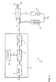
figure 1 shows a diagrammatic view of a gas turbine plant comprising a control device for controlling the pilot gas supply to at least one burner assembly according to the present invention; -
figure 2 shows a detail of the control device infigure 1 ; -
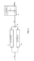
figure 3 shows a detail of the block diagram infigure 2 . - In
figure 1 , reference numeral 1 indicates a gas turbine plant for producing electric energy. - Plant 1 comprises a compressor 3, a combustion chamber 4, a gas turbine 6 and a
generator 7, which transforms the mechanical power supplied by turbine 6 into electric power PEL to be supplied to an electricity network 8 connected togenerator 7 by a switch 9. - Compressor 3 is provided with an
inlet stage 10 having a varying geometry. Theinlet stage 10 comprises a plurality of adjustable inlet stator vanes 11 (diagrammatically shown infigure 1 ), commonly referred to as IGV (Inlet Guide Vane), the position IGVPOS of which may be changed to adjust an air flow rate drawn by the compressor 3 itself. - The combustion chamber 4 is preferably of the annular type and comprises a plurality of
burner assemblies 15, agas supply circuit 16 configured to supply theburner assemblies 15, and acontrol device 17 to control the gas supply to at least oneburner assembly 15. - The
burner assemblies 15 are arranged along a circular path close to an annularperipheral edge 18 of the combustion chamber 4 and face the interior of the combustion chamber 4. - In the non-limiting example described and shown herein, there are twenty-four
burner assemblies 15. - Each
burner assembly 15 extends along an axis and comprises a main peripheral burner (not shown for simplicity) and a central pilot burner 20 (diagrammatically shown infigure 1 ). - The main burner is of the premix type and is preferably arranged around the
pilot burner 20. - The
gas supply circuit 16 comprises a premix supply line (not shown for simplicity), configured to supply the main burners, and apilot supply line 21, configured to supply thepilot burners 20. - In particular, the
pilot supply line 21 comprises acontrol valve 22 and amanifold 23 connected to thepilot burners 20 of eachburner assembly 15. - The opening degree of the
control valve 22 is adjusted by thecontrol device 17 for controlling the pilot gas supply to at least oneburner assembly 15 according to the present invention. - In particular, the
control device 17 is configured to adjust the opening of thecontrol valve 22. - The
control device 17 comprises afirst calculation module 25 configured to calculate a pilot gas basis flow rate QP, asecond calculation module 28 configured to calculate a pilot gas flow rate variation ΔQP, anadder node 29 configured to provide the sum of the pilot gas basis flow rate QP and the pilot gas flow rate variation ΔQP, and avalve control module 30, which is configured to control the opening of thecontrol valve 22 on the basis of the sum of the pilot gas basis flow rate QP and the pilot gas flow rate variation ΔQP. - With reference to
figure 2 , thesecond calculation module 28 is configured to calculate a pilot gas flow rate variation ΔQP on the basis of the position IGVPOS of the adjustable inlet stator vanes 11 and to the electric power PEL supplied bygenerator 7. - The
calculation module 28 comprises acalculation block 35 configured to calculate a pilot gas flow rate variation ΔQPgrad, acorrection calculation block 36 configured to calculate a correction coefficient KIGV for correcting the pilot gas flow rate variation ΔQPgrad on the basis of the position IGVPOS, amultiplier node 37 and a limiter block 38. - The
calculation block 35 is configured to calculate the pilot gas flow rate variation ΔQPgrad on the basis of the electric power PEL supplied bygenerator 7; in particular, thecalculation block 35 is configured to calculate the pilot gas flow rate variation ΔQPgrad on the basis of the electric power gradient GRAD. - Here and hereinafter, the term electric power gradient GRAD means the variation ΔPEL in the electric power supplied by
generator 7 in the time unit. - In particular, the
calculation block 35 comprises agradient module 40, aflow rate module 41 and anactivation module 42. - The
gradient module 40 is configured to calculate the electric power gradient GRAD. - With reference to
figure 3 , thegradient module 40 comprises acalculation module MV 43 configured to calculate a fast average MV of the input signal PEL, acalculation module ML 44 configured to calculate a slow average ML of the input signal PEL, asubtractor node 45 and aconversion module 46. - In particular, the
calculation module MV 43 and thecalculation module ML 44 are configured to calculate a respective moving average of the input electric power signal PEL considering different time intervals. - In particular, the calculation module MV 43 is configured to calculate the fast average MV as a moving average in a time interval of a magnitude order of tenths of seconds. By means of the average, the power oscillations PEL considered as "noise" are substantially filtered.
- The
calculation module MV 43 preferably consists of a series of low pass filters, each being characterized by a time constant from 0.1s to 1s, preferably of 0.4 sec. - The calculation module ML 44 is configured to calculate the slow average ML as a moving average in a time interval of a magnitude order which is higher than tens of seconds. By means of the average, the power oscillations PEL considered as "noise" are substantially filtered.
- The
calculation module ML 44 preferably consists of a series of low pass filters, each being characterized by a time constant from 3s to 10s, preferably of 5 sec. - The
subtractor node 45 obtains the difference between the slow average ML and the fast average MV for achieving the electric power variation ΔPEL. - The
conversion module 46 is configured so as to convert the electric power variation ΔPEL calculated by thesubtractor node 45 into electric power gradient GRAD. In particular, theconversion module 46 is configured to multiply the electric power variation ΔPEL by a coefficient KCONV having a predetermined value, so as to obtain a quantity expressed in MW/min. - With reference to
figure 2 , theflow rate module 41 is configured to calculate a pilot gas flow rate variation ΔQPgrad on the basis of the electric power gradient GRAD calculated by thegradient module 40. - The pilot gas flow rate variation ΔQPgrad thus calculated is fed to the
multiplier node 37 to be corrected by the correction coefficient KIGV. - The
flow rate module 41 preferably calculates the pilot gas flow rate variation ΔQPgrad by means of a table obtained experimentally and containing different values of the pilot gas flow rate variation ΔQPgrad on the basis of the electric power gradient value GRAD. - In a variant, the
flow rate module 41 calculates the pilot gas flow rate variation ΔQP1 by means of a parametric function. - The
activation module 42 is configured to control aselector 45 arranged between thegradient module 40 and theflow rate module 41 through an enabling signal UATT. Preferably, the enabling signal UATT is a predetermined, logical two-state signal (defined by an operator or coming from the overall control system of the plant). - On the basis of the enabling signal UATT,
selector 45 may take two operating positions; a first position whereselector 45 feeds the electric power gradient GRAD to theflow rate module 41, and a second position whereselector 45 feeds a zero signal to theflow rate module 41 in order to obtain a null pilot gas flow rate variation ΔQPgrad. - The
correction calculation block 36 is configured to calculate a correction coefficient KIGV adapted to correct the pilot gas flow rate variation ΔQPgrad on the basis of the position IGVPOS. - In particular, the
correction calculation block 36 calculates the correction coefficient KIGV on the basis of position IGVPOS of the adjustable inlet stator vanes 11, and feeds it to themultiplier node 37. The correction coefficient KIGV preferably has a value in the range between 0 and 1, determined by means of a table obtained experimentally and containing different values of the correction coefficient KIGV on the basis of the position IGVPOS of the adjustable inlet stator vanes 11. - Therefore, a pilot gas flow rate variation ΔQP is outputted from
multiplier 37, which variation has been calculated on the basis of the electric power gradient GRAD and corrected on the basis of the position IGVPOS of the adjustable inlet stator vanes 11. - The limiter block 38 is configured to control a
selector 46 arranged downstream of themultiplier node 37 by means of a selection signal USEL. -
Selector 46 may take two operating positions on the basis of the selection signal value USEL. - When the selection signal USEL has a first value,
selector 36 takes a first position where it connects themultiplier node 37 to theadder node 29. - When the selection signal USEL has a second value,
selector 36 takes a second operating position where it feeds a zero value to theadder node 29. - Preferably, the selection signal USEL is a logical two-state signal calculated by the limiter block 38 on the basis of the position IGVPOS of the adjustable inlet stator vanes 11.
- In particular, the limiter block 38 is configured so as to supply a signal USEL equal to the first value (first operating position of selector 46), if the position IGVPOS is within a configurable range, preferably from about 0.1 to about 0.9, and equal to the second value (second operating position of selector 46), if the position IGVPOS is not within the predefined range.
- In essence, if the position IGVPOS is close to the maximum position value (0) or to the minimum position value (1), the correction of the pilot gas basis flow rate QP as a function of gradient GRAD is inhibited.
- In contrast, if the position IGVPOS is sufficiently far from the maximum and minimum position values, the correction of the pilot gas basis flow rate QP as a function of gradient GRAD is active. In this case, the pilot gas flow rate variation ΔQP from the
multiplier node 37 is fed to theadder node 29 in order to vary the pilot gas basis flow rate QP. - The
control device 17 according to the present invention is advantageously capable of adjusting the pilot gas supply to at least oneburner assembly 15 in a simple and reliable manner, while ensuring high performance of plant 1. - By virtue of the
control device 17, plant 1 is in fact capable of meeting primary power requirements from network 8 up to about 36 MW/min and above. - Indeed, the
control device 17 provides a pilot gas flow rate sufficient for stably supplying the flame and effectively compensating the instabilities caused by quick power variations. - Finally, it is apparent that changes and variations may be made to the control method and to the gas turbine plant described herein without departing from the scope of the appended claims.
Claims (16)
- A control method for controlling the supply of pilot gas to at least one burner assembly (15) of a gas turbine plant (1); the burner assembly (15) comprising at least one pilot burner (20); the method comprising the steps of:- supplying a pilot gas basis flow rate (QP) to the pilot burner (20);- calculating a gradient (GRAD) of the electric power (PEL) supplied by the gas turbine plant (1);- calculating a pilot gas flow rate variation (ΔQP) on the basis of the calculated gradient (GRAD);- modifying the pilot gas basis flow rate (QP) on the basis of the calculated pilot gas flow rate (ΔQP).
- A method according to claim 1, wherein the step of modifying the pilot gas basis flow rate (QP) on the basis of the calculated pilot gas flow rate (ΔQP) comprises the step of modifying the pilot gas basis flow rate (QP) when the position (IGVPOS) of a plurality of adjustable inlet stator vanes (11) of a compressor (3) of the gas turbine plant (1) is included within a predefined interval.
- A method according to claim 2, wherein the predefined interval is about 0.1 to 0.9.
- A method according to claim 2 or 3, comprising the step of not modifying the pilot gas basis flow rate (QP) when the position (IGVPOS) is not included within the predefined interval.
- A method according to any of the preceding claims, wherein the step of modifying the pilot gas flow rate (QP) comprises the step of adding the calculated pilot gas flow rate variation (ΔQP) to the pilot gas basis flow rate (QP).
- A method according to any of preceding claims, comprising the steps of:- calculating a correction coefficient (KIGV) on the basis of the position (IGVPOS) of a plurality of adjustable inlet stator vanes (11) of a compressor (3) of the gas turbine plant (1);- correcting the pilot gas flow rate variation (ΔQP) on the basis of the calculated correction coefficient (KIGV).
- A method according to any of the preceding claims, wherein the step of calculating a gradient (GRAD) of the electric power (PEL) comprises the steps of:- calculating a first moving average (MV) of the electric power (PEL) in a first time interval;- calculating a second moving average (ML) of the electrical power (PEL) in a second time interval longer than the first time interval;- calculating the gradient (GRAD) on the basis of the comparison between the first moving average (MV) and the second moving average (ML).
- A method according to claim 7, wherein the first interval is of the order of tenths of seconds, and the second time interval is of the order of tens of seconds.
- A gas turbine power plant comprising:at least one burner assembly (15), provided with at least one pilot burner (20) fed with a pilot gas basis flow rate (QP);a compressor (3) provided with a plurality of adjustable inlet stator vanes (11);a control device (17) configured :- to calculate a gradient (GRAD) of the electric power (PEL) supplied by the gas turbine plant (1);- to calculate a pilot gas flow rate variation (ΔQP) on the basis of the calculated gradient (GRAD);- to modify the pilot gas basis flow rate (QP) on the basis of the calculated pilot gas flow rate (ΔQP).
- A plant according to claim 9, wherein the control device (17) is configured to modify the pilot gas basis flow rate (QP) to supply to the pilot burner (20) on the basis of the calculated pilot gas flow rate (ΔQP) when the position (IGVPOS) of the plurality of adjustable inlet stator vanes (11) is included within a predefined range.
- A plant according to claim 10, wherein the predefined range is about 0.1 to 0.9.
- A plant according to claim 10 or 11, wherein the control device (17) is configured to not modify the pilot gas basis flow rate (QP) when the position (IGVPOS) is not included within the predefined range.
- A plant according to any of claims 9 to 12, wherein the control device (17) is configured to add the calculated pilot gas flow rate variation (ΔQP) to the pilot gas basis flow rate (QP).
- A plant according to any of claims 9 to 13, wherein the control device (17) is configured to:- calculate a correction coefficient (KIGV) on the basis of the position (IGVPOS) of the plurality of adjustable inlet stator vanes (11);- correct the pilot gas flow rate variation (ΔQP) on the basis of the calculated correction coefficient (KIGV).
- A plant according to any of claims 9 to 14, wherein the control device (17) is configured to calculate the gradient (GRAD) of the electric power (PEL) supplied by the gas turbine plant (1) on the basis of the comparison between a first moving average (MV) of the electric power (PEL) and a second moving average (ML) of the electrical power (PEL); the first moving average (MV) being calculated in a first time interval and the second moving average (ML) being calculated in a second time interval longer than the first time interval.
- A plant according to claim 15, wherein the first time interval is in the range of tenths of seconds and the second time interval is in the range of tens of seconds.
Applications Claiming Priority (1)
| Application Number | Priority Date | Filing Date | Title |
|---|---|---|---|
| IT000811A ITMI20110811A1 (en) | 2011-05-10 | 2011-05-10 | METHOD OF CONTROL TO CONTROL THE GAS FEED DRIVES AT LEAST ONE BURNER GROUP OF A GAS TURBINE PLANT AND GAS TURBINE SYSTEM |
Publications (2)
| Publication Number | Publication Date |
|---|---|
| EP2522908A1 true EP2522908A1 (en) | 2012-11-14 |
| EP2522908B1 EP2522908B1 (en) | 2018-01-03 |
Family
ID=44513032
Family Applications (1)
| Application Number | Title | Priority Date | Filing Date |
|---|---|---|---|
| EP12167575.5A Active EP2522908B1 (en) | 2011-05-10 | 2012-05-10 | Control method for controlling the pilot gas supply to at least one burner assembly of a gas turbine plant and gas turbine plant |
Country Status (2)
| Country | Link |
|---|---|
| EP (1) | EP2522908B1 (en) |
| IT (1) | ITMI20110811A1 (en) |
Cited By (1)
| Publication number | Priority date | Publication date | Assignee | Title |
|---|---|---|---|---|
| ITMI20131817A1 (en) * | 2013-10-31 | 2015-05-01 | Ansaldo Energia Spa | METHOD AND CONTROL DEVICE TO CONTROL A GAS TURBINE ELECTRIC ENERGY PRODUCTION PLANT |
Citations (3)
| Publication number | Priority date | Publication date | Assignee | Title |
|---|---|---|---|---|
| US20070089395A1 (en) * | 2005-09-14 | 2007-04-26 | Mitsubishi Heavy Industries, Ltd. | Combustion control device for gas turbine |
| WO2009016665A1 (en) * | 2007-08-01 | 2009-02-05 | Ansaldo Energia S.P.A. | Device and method for regulating the exhaust temperature of a gas turbine |
| EP2261487A1 (en) * | 2008-11-28 | 2010-12-15 | Mitsubishi Heavy Industries, Ltd. | Gas turbine controller |
-
2011
- 2011-05-10 IT IT000811A patent/ITMI20110811A1/en unknown
-
2012
- 2012-05-10 EP EP12167575.5A patent/EP2522908B1/en active Active
Patent Citations (3)
| Publication number | Priority date | Publication date | Assignee | Title |
|---|---|---|---|---|
| US20070089395A1 (en) * | 2005-09-14 | 2007-04-26 | Mitsubishi Heavy Industries, Ltd. | Combustion control device for gas turbine |
| WO2009016665A1 (en) * | 2007-08-01 | 2009-02-05 | Ansaldo Energia S.P.A. | Device and method for regulating the exhaust temperature of a gas turbine |
| EP2261487A1 (en) * | 2008-11-28 | 2010-12-15 | Mitsubishi Heavy Industries, Ltd. | Gas turbine controller |
Cited By (4)
| Publication number | Priority date | Publication date | Assignee | Title |
|---|---|---|---|---|
| ITMI20131817A1 (en) * | 2013-10-31 | 2015-05-01 | Ansaldo Energia Spa | METHOD AND CONTROL DEVICE TO CONTROL A GAS TURBINE ELECTRIC ENERGY PRODUCTION PLANT |
| WO2015063735A1 (en) * | 2013-10-31 | 2015-05-07 | Ansaldo Energia S.P.A. | Control method and device for controlling a gas turbine plant for electrical energy production |
| CN105899785A (en) * | 2013-10-31 | 2016-08-24 | 安萨尔多能源公司 | Control method and device for controlling a gas turbine plant for electrical energy production |
| CN105899785B (en) * | 2013-10-31 | 2017-11-10 | 安萨尔多能源公司 | Control method and device for controlling gas turbine plant for power generation |
Also Published As
| Publication number | Publication date |
|---|---|
| ITMI20110811A1 (en) | 2012-11-11 |
| EP2522908B1 (en) | 2018-01-03 |
Similar Documents
| Publication | Publication Date | Title |
|---|---|---|
| US9441545B2 (en) | Fuel supply apparatus, fuel-flow-rate-control unit, and gas-turbine power generating plant | |
| US10208678B2 (en) | Gas turbine combustion control device and combustion control method and program therefor | |
| US8800296B2 (en) | Gas turbine control method and gas turbine power generating apparatus | |
| US8694170B2 (en) | Gas turbine operation control device and operation control method | |
| US11773789B2 (en) | Flow volume ratio calculation device, control device equipped with same, gas turbine plant equipped with this control device, flow volume ratio calculation method, and fuel line control method | |
| US9306395B2 (en) | Wind turbine controller applying differential pole control algorithm | |
| US9822710B2 (en) | Combustion device with pulsed fuel split | |
| US10669959B2 (en) | Control device, system, control method, power control device, gas turbine, and power control method | |
| KR101885489B1 (en) | Flow ratio calculation device, control device provided with same, gas turbine plant provided with said control device, flow ratio calculation method, and method for controlling fuel system | |
| US11421886B2 (en) | Fuel flow rate setting method, device for implementing said method, and gas turbine plant provided with said device | |
| CN106249589B (en) | The load dynamic Feedforward method of thermal power unit plant | |
| EP2846021B1 (en) | Two-shaft gas turbine | |
| EP2522908B1 (en) | Control method for controlling the pilot gas supply to at least one burner assembly of a gas turbine plant and gas turbine plant | |
| US10815905B2 (en) | Fuel control method for gas turbine, control device for executing said method, and gas turbine installation provided with said control device | |
| US10221777B2 (en) | Gas turbine combustion control device and combustion control method and program therefor | |
| US20100312408A1 (en) | Control device and method of a gas turbine electric energy production plant | |
| DiCampli et al. | Grid stability: Gas turbines for primary reserve | |
| KR101253750B1 (en) | An apparatus controlling extraction steam of a top heater to improve speed regulation rate of power plant | |
| RU2645821C1 (en) | Device for pressure regulation in gas line with turbo-expander | |
| EP2239641B1 (en) | Device and method for determining operating parameters of a gas-turbine plant | |
| EP2249006B1 (en) | Device and method for controlling the exhaust temperature of a gas turbine of a power plant | |
| EP3063392B1 (en) | Control method and device for controlling a gas turbine plant for electrical energy production | |
| JP2017103868A (en) | Power control apparatus and power control method | |
| JP2014114794A (en) | Gas turbine control device and method | |
| US20140345290A1 (en) | Method for stabilizing a grid frequency with a gas turbine in mixed fuel operation |
Legal Events
| Date | Code | Title | Description |
|---|---|---|---|
| PUAI | Public reference made under article 153(3) epc to a published international application that has entered the european phase |
Free format text: ORIGINAL CODE: 0009012 |
|
| AK | Designated contracting states |
Kind code of ref document: A1 Designated state(s): AL AT BE BG CH CY CZ DE DK EE ES FI FR GB GR HR HU IE IS IT LI LT LU LV MC MK MT NL NO PL PT RO RS SE SI SK SM TR |
|
| AX | Request for extension of the european patent |
Extension state: BA ME |
|
| 17P | Request for examination filed |
Effective date: 20130514 |
|
| 17Q | First examination report despatched |
Effective date: 20161117 |
|
| GRAP | Despatch of communication of intention to grant a patent |
Free format text: ORIGINAL CODE: EPIDOSNIGR1 |
|
| INTG | Intention to grant announced |
Effective date: 20170720 |
|
| GRAS | Grant fee paid |
Free format text: ORIGINAL CODE: EPIDOSNIGR3 |
|
| GRAA | (expected) grant |
Free format text: ORIGINAL CODE: 0009210 |
|
| AK | Designated contracting states |
Kind code of ref document: B1 Designated state(s): AL AT BE BG CH CY CZ DE DK EE ES FI FR GB GR HR HU IE IS IT LI LT LU LV MC MK MT NL NO PL PT RO RS SE SI SK SM TR |
|
| REG | Reference to a national code |
Ref country code: GB Ref legal event code: FG4D |
|
| REG | Reference to a national code |
Ref country code: CH Ref legal event code: EP Ref country code: AT Ref legal event code: REF Ref document number: 960633 Country of ref document: AT Kind code of ref document: T Effective date: 20180115 |
|
| REG | Reference to a national code |
Ref country code: IE Ref legal event code: FG4D |
|
| REG | Reference to a national code |
Ref country code: DE Ref legal event code: R096 Ref document number: 602012041528 Country of ref document: DE |
|
| REG | Reference to a national code |
Ref country code: NL Ref legal event code: MP Effective date: 20180103 |
|
| REG | Reference to a national code |
Ref country code: LT Ref legal event code: MG4D |
|
| REG | Reference to a national code |
Ref country code: AT Ref legal event code: MK05 Ref document number: 960633 Country of ref document: AT Kind code of ref document: T Effective date: 20180103 |
|
| PG25 | Lapsed in a contracting state [announced via postgrant information from national office to epo] |
Ref country code: NL Free format text: LAPSE BECAUSE OF FAILURE TO SUBMIT A TRANSLATION OF THE DESCRIPTION OR TO PAY THE FEE WITHIN THE PRESCRIBED TIME-LIMIT Effective date: 20180103 |
|
| PG25 | Lapsed in a contracting state [announced via postgrant information from national office to epo] |
Ref country code: HR Free format text: LAPSE BECAUSE OF FAILURE TO SUBMIT A TRANSLATION OF THE DESCRIPTION OR TO PAY THE FEE WITHIN THE PRESCRIBED TIME-LIMIT Effective date: 20180103 Ref country code: CY Free format text: LAPSE BECAUSE OF FAILURE TO SUBMIT A TRANSLATION OF THE DESCRIPTION OR TO PAY THE FEE WITHIN THE PRESCRIBED TIME-LIMIT Effective date: 20180103 Ref country code: NO Free format text: LAPSE BECAUSE OF FAILURE TO SUBMIT A TRANSLATION OF THE DESCRIPTION OR TO PAY THE FEE WITHIN THE PRESCRIBED TIME-LIMIT Effective date: 20180403 Ref country code: FI Free format text: LAPSE BECAUSE OF FAILURE TO SUBMIT A TRANSLATION OF THE DESCRIPTION OR TO PAY THE FEE WITHIN THE PRESCRIBED TIME-LIMIT Effective date: 20180103 Ref country code: ES Free format text: LAPSE BECAUSE OF FAILURE TO SUBMIT A TRANSLATION OF THE DESCRIPTION OR TO PAY THE FEE WITHIN THE PRESCRIBED TIME-LIMIT Effective date: 20180103 Ref country code: LT Free format text: LAPSE BECAUSE OF FAILURE TO SUBMIT A TRANSLATION OF THE DESCRIPTION OR TO PAY THE FEE WITHIN THE PRESCRIBED TIME-LIMIT Effective date: 20180103 |
|
| PG25 | Lapsed in a contracting state [announced via postgrant information from national office to epo] |
Ref country code: SE Free format text: LAPSE BECAUSE OF FAILURE TO SUBMIT A TRANSLATION OF THE DESCRIPTION OR TO PAY THE FEE WITHIN THE PRESCRIBED TIME-LIMIT Effective date: 20180103 Ref country code: AT Free format text: LAPSE BECAUSE OF FAILURE TO SUBMIT A TRANSLATION OF THE DESCRIPTION OR TO PAY THE FEE WITHIN THE PRESCRIBED TIME-LIMIT Effective date: 20180103 Ref country code: LV Free format text: LAPSE BECAUSE OF FAILURE TO SUBMIT A TRANSLATION OF THE DESCRIPTION OR TO PAY THE FEE WITHIN THE PRESCRIBED TIME-LIMIT Effective date: 20180103 Ref country code: RS Free format text: LAPSE BECAUSE OF FAILURE TO SUBMIT A TRANSLATION OF THE DESCRIPTION OR TO PAY THE FEE WITHIN THE PRESCRIBED TIME-LIMIT Effective date: 20180103 Ref country code: BG Free format text: LAPSE BECAUSE OF FAILURE TO SUBMIT A TRANSLATION OF THE DESCRIPTION OR TO PAY THE FEE WITHIN THE PRESCRIBED TIME-LIMIT Effective date: 20180403 Ref country code: IS Free format text: LAPSE BECAUSE OF FAILURE TO SUBMIT A TRANSLATION OF THE DESCRIPTION OR TO PAY THE FEE WITHIN THE PRESCRIBED TIME-LIMIT Effective date: 20180503 Ref country code: GR Free format text: LAPSE BECAUSE OF FAILURE TO SUBMIT A TRANSLATION OF THE DESCRIPTION OR TO PAY THE FEE WITHIN THE PRESCRIBED TIME-LIMIT Effective date: 20180404 Ref country code: PL Free format text: LAPSE BECAUSE OF FAILURE TO SUBMIT A TRANSLATION OF THE DESCRIPTION OR TO PAY THE FEE WITHIN THE PRESCRIBED TIME-LIMIT Effective date: 20180103 |
|
| REG | Reference to a national code |
Ref country code: DE Ref legal event code: R097 Ref document number: 602012041528 Country of ref document: DE |
|
| PG25 | Lapsed in a contracting state [announced via postgrant information from national office to epo] |
Ref country code: AL Free format text: LAPSE BECAUSE OF FAILURE TO SUBMIT A TRANSLATION OF THE DESCRIPTION OR TO PAY THE FEE WITHIN THE PRESCRIBED TIME-LIMIT Effective date: 20180103 Ref country code: RO Free format text: LAPSE BECAUSE OF FAILURE TO SUBMIT A TRANSLATION OF THE DESCRIPTION OR TO PAY THE FEE WITHIN THE PRESCRIBED TIME-LIMIT Effective date: 20180103 Ref country code: EE Free format text: LAPSE BECAUSE OF FAILURE TO SUBMIT A TRANSLATION OF THE DESCRIPTION OR TO PAY THE FEE WITHIN THE PRESCRIBED TIME-LIMIT Effective date: 20180103 |
|
| PLBE | No opposition filed within time limit |
Free format text: ORIGINAL CODE: 0009261 |
|
| STAA | Information on the status of an ep patent application or granted ep patent |
Free format text: STATUS: NO OPPOSITION FILED WITHIN TIME LIMIT |
|
| PG25 | Lapsed in a contracting state [announced via postgrant information from national office to epo] |
Ref country code: SM Free format text: LAPSE BECAUSE OF FAILURE TO SUBMIT A TRANSLATION OF THE DESCRIPTION OR TO PAY THE FEE WITHIN THE PRESCRIBED TIME-LIMIT Effective date: 20180103 Ref country code: SK Free format text: LAPSE BECAUSE OF FAILURE TO SUBMIT A TRANSLATION OF THE DESCRIPTION OR TO PAY THE FEE WITHIN THE PRESCRIBED TIME-LIMIT Effective date: 20180103 Ref country code: DK Free format text: LAPSE BECAUSE OF FAILURE TO SUBMIT A TRANSLATION OF THE DESCRIPTION OR TO PAY THE FEE WITHIN THE PRESCRIBED TIME-LIMIT Effective date: 20180103 Ref country code: CZ Free format text: LAPSE BECAUSE OF FAILURE TO SUBMIT A TRANSLATION OF THE DESCRIPTION OR TO PAY THE FEE WITHIN THE PRESCRIBED TIME-LIMIT Effective date: 20180103 |
|
| 26N | No opposition filed |
Effective date: 20181005 |
|
| REG | Reference to a national code |
Ref country code: CH Ref legal event code: PL |
|
| GBPC | Gb: european patent ceased through non-payment of renewal fee |
Effective date: 20180510 |
|
| REG | Reference to a national code |
Ref country code: BE Ref legal event code: MM Effective date: 20180531 |
|
| PG25 | Lapsed in a contracting state [announced via postgrant information from national office to epo] |
Ref country code: MC Free format text: LAPSE BECAUSE OF FAILURE TO SUBMIT A TRANSLATION OF THE DESCRIPTION OR TO PAY THE FEE WITHIN THE PRESCRIBED TIME-LIMIT Effective date: 20180103 |
|
| REG | Reference to a national code |
Ref country code: IE Ref legal event code: MM4A |
|
| PG25 | Lapsed in a contracting state [announced via postgrant information from national office to epo] |
Ref country code: SI Free format text: LAPSE BECAUSE OF FAILURE TO SUBMIT A TRANSLATION OF THE DESCRIPTION OR TO PAY THE FEE WITHIN THE PRESCRIBED TIME-LIMIT Effective date: 20180103 Ref country code: CH Free format text: LAPSE BECAUSE OF NON-PAYMENT OF DUE FEES Effective date: 20180531 Ref country code: LI Free format text: LAPSE BECAUSE OF NON-PAYMENT OF DUE FEES Effective date: 20180531 |
|
| PG25 | Lapsed in a contracting state [announced via postgrant information from national office to epo] |
Ref country code: LU Free format text: LAPSE BECAUSE OF NON-PAYMENT OF DUE FEES Effective date: 20180510 |
|
| PG25 | Lapsed in a contracting state [announced via postgrant information from national office to epo] |
Ref country code: FR Free format text: LAPSE BECAUSE OF NON-PAYMENT OF DUE FEES Effective date: 20180531 Ref country code: GB Free format text: LAPSE BECAUSE OF NON-PAYMENT OF DUE FEES Effective date: 20180510 Ref country code: IE Free format text: LAPSE BECAUSE OF NON-PAYMENT OF DUE FEES Effective date: 20180510 |
|
| PG25 | Lapsed in a contracting state [announced via postgrant information from national office to epo] |
Ref country code: BE Free format text: LAPSE BECAUSE OF NON-PAYMENT OF DUE FEES Effective date: 20180531 |
|
| PG25 | Lapsed in a contracting state [announced via postgrant information from national office to epo] |
Ref country code: MT Free format text: LAPSE BECAUSE OF NON-PAYMENT OF DUE FEES Effective date: 20180510 |
|
| PG25 | Lapsed in a contracting state [announced via postgrant information from national office to epo] |
Ref country code: TR Free format text: LAPSE BECAUSE OF FAILURE TO SUBMIT A TRANSLATION OF THE DESCRIPTION OR TO PAY THE FEE WITHIN THE PRESCRIBED TIME-LIMIT Effective date: 20180103 |
|
| PG25 | Lapsed in a contracting state [announced via postgrant information from national office to epo] |
Ref country code: HU Free format text: LAPSE BECAUSE OF FAILURE TO SUBMIT A TRANSLATION OF THE DESCRIPTION OR TO PAY THE FEE WITHIN THE PRESCRIBED TIME-LIMIT; INVALID AB INITIO Effective date: 20120510 Ref country code: PT Free format text: LAPSE BECAUSE OF FAILURE TO SUBMIT A TRANSLATION OF THE DESCRIPTION OR TO PAY THE FEE WITHIN THE PRESCRIBED TIME-LIMIT Effective date: 20180103 |
|
| PG25 | Lapsed in a contracting state [announced via postgrant information from national office to epo] |
Ref country code: MK Free format text: LAPSE BECAUSE OF NON-PAYMENT OF DUE FEES Effective date: 20180103 |
|
| P01 | Opt-out of the competence of the unified patent court (upc) registered |
Effective date: 20240430 |
|
| PGFP | Annual fee paid to national office [announced via postgrant information from national office to epo] |
Ref country code: DE Payment date: 20250519 Year of fee payment: 14 |
|
| PGFP | Annual fee paid to national office [announced via postgrant information from national office to epo] |
Ref country code: IT Payment date: 20250530 Year of fee payment: 14 |