EP2522768A1 - Fabric treating appliance provided with steam generation and method for controlling the amount of generated steam - Google Patents
Fabric treating appliance provided with steam generation and method for controlling the amount of generated steam Download PDFInfo
- Publication number
- EP2522768A1 EP2522768A1 EP11165750A EP11165750A EP2522768A1 EP 2522768 A1 EP2522768 A1 EP 2522768A1 EP 11165750 A EP11165750 A EP 11165750A EP 11165750 A EP11165750 A EP 11165750A EP 2522768 A1 EP2522768 A1 EP 2522768A1
- Authority
- EP
- European Patent Office
- Prior art keywords
- steam
- evaporated water
- water
- evaporated
- appliance
- Prior art date
- Legal status (The legal status is an assumption and is not a legal conclusion. Google has not performed a legal analysis and makes no representation as to the accuracy of the status listed.)
- Granted
Links
Images


Classifications
-
- D—TEXTILES; PAPER
- D06—TREATMENT OF TEXTILES OR THE LIKE; LAUNDERING; FLEXIBLE MATERIALS NOT OTHERWISE PROVIDED FOR
- D06F—LAUNDERING, DRYING, IRONING, PRESSING OR FOLDING TEXTILE ARTICLES
- D06F39/00—Details of washing machines not specific to a single type of machines covered by groups D06F9/00 - D06F27/00
- D06F39/40—Steam generating arrangements
Definitions
- the present invention relates to a fabric treating appliance, provided with steam generation and a method for controlling the amount of generated steam in the same.
- the provision of steam can be envisaged for different reasons depending on the fabric treatment appliance in which a steamer generator is present, for example, the latter may be used to heat water, heat a load of fabric items and any water absorbed by the fabric items, de-wrinkle or refresh fabric items, remove odors from fabric items, sanitize the fabric items, sanitize components of the fabric treatment appliance and so on.
- fabric treatment appliances provided with steam generation comprise a steam generator supplied with water for the conversion to steam thereof.
- a steam generator supplied with water for the conversion to steam thereof.
- U.S. Patent Application 2009/0056389 discloses a washing machine comprising a water supply for filling a steam generation chamber of the steam generator with water, and a heating element of the steam generator heating the water present in the steam generation chamber to generate steam. Steam generated in the steam generation chamber flows from the steam generation chamber to a fabric treatment chamber via a steam supply conduit attached to the steam generator.
- the European Patent application EP 1 873 297 discloses two different methods for controlling the steam generation in fabric treating appliance. A first one consists in detecting the water level and the temperature in a steam generation chamber and turning the heater creating the steam on or off according to the values detected. Applicants have noted that this control method is suitable only for continuous steam generation, while it does not allow a precise control of steam when steam is required only in some working cycles (e.g. for de-wrinkling) of the appliance.
- the duration of a refreshing/de-wrinkling cycle is pre-determined and specified into a digital memory of the machine electronic controller: the user selects the program and specifies the textile and the amount of the load and, according to these inputs the electronic controller selects the cycle time duration: so, the duration of this cycle is fixed and does not depend on non user-set external parameters, as explained also in U.S. Patent Application No. 2009/0056389 .
- the second method disclosed in the European Patent application EP 1 873 297 is based on defining a variable operation limit time of the steamer according to several parameters, namely a temperature variation of the water, a level of a voltage applied to the heater and a quantity of water accommodated in the steam generator.
- the second method also comprises a step of updating the operation limit time by being decided at least twice. Namely, the operation limit time can be updated by considering a temperature variation of the water in the course of driving the heater.
- the technical problem underlying the present invention is to provide a control of the steam generation which overcomes the drawbacks mentioned above with reference to the known art.
- the present invention provides several relevant advantages.
- the main advantage lies in that the fabric treating appliance provided with steam generation and the respective control method according to the present invention, allows providing steam cycles according to the user's inputs and settings with very precise amounts of generated steam, thus avoiding both insufficient steam in order to perform the inputted cycle and energy waste.
- the manufacturing of a fabric treating appliance according to the present invention does not require any additional cost to a standard machine.
- the present invention will be described, by way of non-limiting examples, with reference to a laundry machine provided with steam generation, in particular for providing it with refreshing/de-wrinkling cycles capability. It will be apparent to the one skilled in the art that the same inventive concept can be applied also to different fabric treating appliance such as washing machines, clothes dryers, fabric refreshing machines and the like in order to heat water, heat a load of fabric items, removing odors therefrom, sanitize them, sanitize components of the fabric treatment appliance and so on. Alternatively or in addition, the steam is provided for the washing cycle itself.
- a laundry machine 1 comprises a cabinet 10 configuring an exterior of the laundry machine, a tub 20, for example a cylindrical one horizontally supported within the cabinet 10 to store water therein, a drum 30 for holding fabric items, rotatably provided within the tub 20 and having preferably perforated holes (not shown in the drawing) for enabling water and steam to be introduced into the drum 30, a driving motor (also not shown) for driving the drum 30, and at least one steam generator 50 for supplying steam into the drum 30.
- the steam generator 50 is a tank-type steam generator, storing a volume of water and heating it by an heater (not shown) in order to convert the water to steam.
- the steam generator 50 may be an in-line steam generator, such as the one described in U.S. patent application Ser. No. 11/848,550 "Fabric Treatment appliance with steam generator having a variable thermal output", that converts the water to steam as the former flows through the steam generator.
- the laundry machine 1 further comprises a control panel 40 connected to a respective control unit (not shown) for allowing the user to input different parameters of washing and, in particular, steaming cycles, as will be better described in the following.
- the control unit is associated to a processing unit and a storage medium (both not shown) such as an EPROM memory or any other electronic non-volatile memory capable of storing information relating to the washing and steaming cycles.
- a flow chart shows a method for controlling the amount of generated steam in the laundry machine 1 provided with steam generator 50 according to the present embodiment.
- the method comprises a first step S1 of inputting specific conditions and parameters of the desired steam cycle to be performed by the laundry machine 1. More precisely, by means of the control panel 40, a user can select a plurality of different parameters, which will be called in the following, globally, "user's inputs".
- the available possibilities comprise:
- the amount of load can be automatically determined by a load sensor positioned in the machine 1 and therefore there is no need that this value is inputted by the user.
- a torque sensor can be used for the same purpose. Setting the above user's inputs results in a selection of a desired steam cycle.
- a control time t c is also defined.
- t c represents the sampling rate at which the amount of water evaporated by the steam is measured, as will be better described in the following. It should be noted that this parameter is preferably not inputted by the user, but it is determined in advance during the setup of the laundry machine, i.e. when the laundry machine is installed at the user's home it is already fixed and stored in the same.
- step S2 a total amount of water to be evaporated in the whole steaming cycle on the basis of the above-mentioned user's inputs is calculated.
- a Table T1 correlating amounts of water to be evaporated to the specific selected user's inputs of the desired steam cycle, is stored in the storage medium.
- This Table is obtained by means of several field tests which have been performed on all models of appliance including a steam generator according to the invention and have been preferably realized on the premises of the Applicants when the various appliances are built.
- the Table is "machine dependent" and - even for the same model - it can differ due to the fact that the same model is sold in different countries having different requirements or preferences.
- Table 1 depends, among others, on the machine model and on the market in which the machine 1 is distributed. Given the selected user's inputs corresponding to a desired steam cycle as indicated above, stored Table T1 is looked up in order to retrieve from the same a threshold value of evaporated water EW th corresponding to the total amount of water that has to be evaporated in order to achieve the selected steam cycle.
- the threshold values EW th stored in Table is determined experimentally, and it may depend on the specific design of the laundry machine, therefore a given model of appliance may have stored a Table T1 including different values than another appliance's model or appliance for another market.
- step S3 the control unit activates the heater of the steam generator 50 in order to produce steam which is supplied to the drum 30.
- the control unit initializes a variable EW which defines the total amount of evaporated water EW at a given point in time during the steaming cycle, which is set equal to 0 at the beginning of the cycle itself.
- the total amount of water evaporated in a specific time interval during the steam cycle depends theoretically substantially only on the power/energy provided thereto, which corresponds to the power absorbed by the heater.
- the power provided to the appliance is used to heat water: there are intrinsic losses and thermal inertia that prevents to make a one-to-one correspondence between the power and the total amount of water evaporated.
- a steamer system i.e.
- control unit calculates in a very precise way the amount of water actually evaporated.
- the method according to the present invention comprises a step S4 wherein the control unit measures an average RMS voltage value V RMSc applied to the heater of the steam generator, during for example the same control time t c previously defined.
- the laundry machine according to the present invention comprises a voltmeter or any other voltage measuring device operatively connected to the control unit.
- another parameter can be measured for example by detecting the current applied to the heater and then calculating its RMS, I RMSc , as long as such a value is available to the control unit.
- step S5 of the method of the invention using the look-up Table T2, the amount of water EW c evaporated during said time interval t c . is determined in the control unit.
- Table T2 correlates respective values of V RMSc to partial amounts of the amount of water EW c evaporated in a given interval.
- additional and/or different parameters can be considered in order to make a one-to-one correlation between such a parameter and the evaporated water, for example by considering the peak voltage value of the mains.
- the actual value of total amount of evaporated water EW is compared with the threshold value EW th previously determined according to the user's inputs in step S8.
- a heater controller connected to said control unit turns off the heater of the steam generation, thus terminating the steam cycle.
- step S4 is repeated so that the control unit measures a new average RMS voltage V RMSc in a successive time interval t c+1 and calculate a new amount of evaporated water EW c+1 in this interval.
- the average RMS voltage V RMSc is variable during the overall steam cycle, as the mains voltage is subjected to considerable oscillations, since a 10% variation from the nominal value is allowed and higher variations are to be expected.
- control unit by means of the processing unit will determine a new partial amount of evaporated water EW c+1 to be summed to the total of evaporated water EW previously determined.
- EW is updated at each interval t c .
- step S8 is repeated checking again if the new total amount of evaporated water EW has reached the threshold value EW th . Again, if the new total amount of evaporated water EW is still lower than the threshold value EW th steps S4 and S5 will be repeated, otherwise the heater is turned off and the cycle is terminated.
- the control unit preferably, according to an optional step of the method of the invention, also further controls the quantity of water in the steam generator 50, e.g. the water contained in the tank if a tank-type generator is used. If the water level detected by the control unit is lower than a predetermined level (for example defined by the amount of water required to completely cover the heater) than a refill procedure is performed in step S7. In fact, in case of water shortage in the tank, the amount of generated steam can be lower than the expected one in a given time interval since the heater can be only partially submersed by water. This can also result in malfunction or damage of the heater or other parts in the steam generator 50, due to overheating.
- a predetermined level for example defined by the amount of water required to completely cover the heater
- This refill procedure for example consists in opening a water supply valve and it can envisage either a temporary interruption of the steam generation or a continuation thereof.
- the transient condition determined by the refill operation can be taken into account when determining the partial amount of evaporated water.
- the appliance according to the present invention can provide coherent and consistent steam cycles as the amount of generated steam can be precisely calculated since it is directly connected to the RMS voltage.
- a suitable sampling rate for measuring the partial amount of evaporated water it possible to finely control the steam cycle by precisely determining the total amount of evaporated water.
- a suitable sampling rate e.g. each 1 sec., 1 min., etc
- sampling rate - and, accordingly, the selected time intervals - can vary during the steam cycle, being shorter during particular phases of the cycle when a more precise control is required. In fact, the shorter the time intervals are, the more reliable the control of generated steam is.
- Table T1 and Table T2 can be easily obtained as their values can be determined experimentally.
- Table T1 can be obtained by experimentally determining the amount of steam required for a suitable treating of the fabrics, and Table T2 can be built by means of laboratory tests on the steam generator and on the fabric appliance comprising it.
- Table T1 or Table T2 can be substituted by analytical functions, for example determined by interpolating or fitting the experimental values obtained in the field tests.
- phase S5 in fig. 3 and phase S5" in fig. 4
- phase S5' in fig. 3 and phase S5" in fig. 4
- a steam generation phase can comprise several operative sub-phases, e.g. a start up (i.e. a cycle initialization), a transient (i.e. the condition during the refill operations) and a working phase.
- a start up i.e. a cycle initialization
- a transient i.e. the condition during the refill operations
- a working phase i.e. the condition during the refill operations
- the heater operates according to different conditions and the amount of steam produced during such phases is accordingly different: in the start-up period for example the drum and the other parts of the appliance are all rather “cold” therefore a low steam production is expected; in the refill phase on the contrary the appliance's elements are already at a certain "relatively high” temperature (i.e. above room temperature) and therefore a higher production of steam in the same interval is expected.
- Table T2' takes into account different partial amounts of evaporated water on the basis of the steam phase condition, i.e. in which subphase the steamer is working.
- the control unit can consider start up values for the partial amount of evaporated water during the first minutes of the steam cycles, transient ones when refill of the water tank occurs, and working values in all other cases. More precisely, in this case to a single column of voltage values, three different columns of values of partial amounts of evaporated water EW' c are corresponding namely a first column for the start up the cycle, a second one for a transient phase and a third one for the working phase.
- step S5' includes the following: the control unit, after detecting the voltage value V RMSc , looks up the value of partial amount of evaporated water EW c considering the first column during the cycle initialization, the second one during refill operations, and the third one in all other cases.
- the update of the evaporated water EW' c is performed as in the previous embodiment continuously updating the value EW'.
- the correlation between the partial amounts of evaporated water EW" c and the power consumption in this further embodiment also takes into consideration the effect of the temperature in the steam generator 50.
- the amount of evaporated water gradually decreases for temperatures in the steam generator 50 lower than 100°C, being virtually zero below 80°C.
- the partial amounts of evaporated water are corrected by a function of the temperature f(T) varying from 0 (below 80°C) to 1 (above 100°C) depending on the detected temperature.
- the value of the function f(T) varies linearly according to the temperature. According to a different embodiment not shown, also a different dependency can be envisaged.
- the method according to the present embodiment of fig. 4 comprises a further step S9 of detecting the temperature T in the steam generator 50 before the step S5" can be performed . Then, in step S5" the control unit will look up the value of partial amount of water EW" c in Table T2", first obtaining the value f(T) according to the measured temperature T and then multiplying the value f(T) for a parameter fixed in Table T2" and which depends on the measured V RMSc .
Landscapes
- Engineering & Computer Science (AREA)
- Textile Engineering (AREA)
- Control Of Washing Machine And Dryer (AREA)
Abstract
Description
- The present invention relates to a fabric treating appliance, provided with steam generation and a method for controlling the amount of generated steam in the same.
- Recently, the use of steam generation functionality has become quite common in several types of fabric treatment appliances, such as washing machines, clothes dryers, fabric refreshing machines and the like.
- The provision of steam can be envisaged for different reasons depending on the fabric treatment appliance in which a steamer generator is present, for example, the latter may be used to heat water, heat a load of fabric items and any water absorbed by the fabric items, de-wrinkle or refresh fabric items, remove odors from fabric items, sanitize the fabric items, sanitize components of the fabric treatment appliance and so on.
- In particular, in domestic washing machines clothes refreshment functionality by means of steam has become more and more important.
- An additional important application is the use of steam during washing as disclosed in
WO 2006/101372 by LG Electronics. In this patent application, the different advantages of steam in a washing cycle are explained: in the pre-wash phase, while the water loads into the wash tub, the steam works with the water to help soak the fabrics more thoroughly; during the washing phase, if the steam is added while the detergent is mixed with the water, the steam increases the temperature of the wash tub to improve the cleaning power, which also helps to activate the detergent; in the post-wash phase, the steam lends more high temperatures to the tub to sterilize the clothes. It also softens the clothes to remove hard wrinkles that formed while the clothes tossed in the tub. - In general, fabric treatment appliances provided with steam generation according to the known art comprise a steam generator supplied with water for the conversion to steam thereof. For example
U.S. Patent Application 2009/0056389 discloses a washing machine comprising a water supply for filling a steam generation chamber of the steam generator with water, and a heating element of the steam generator heating the water present in the steam generation chamber to generate steam. Steam generated in the steam generation chamber flows from the steam generation chamber to a fabric treatment chamber via a steam supply conduit attached to the steam generator. - The European
Patent application EP 1 873 297 discloses two different methods for controlling the steam generation in fabric treating appliance. A first one consists in detecting the water level and the temperature in a steam generation chamber and turning the heater creating the steam on or off according to the values detected. Applicants have noted that this control method is suitable only for continuous steam generation, while it does not allow a precise control of steam when steam is required only in some working cycles (e.g. for de-wrinkling) of the appliance. Indeed, in the know art the duration of a refreshing/de-wrinkling cycle is pre-determined and specified into a digital memory of the machine electronic controller: the user selects the program and specifies the textile and the amount of the load and, according to these inputs the electronic controller selects the cycle time duration: so, the duration of this cycle is fixed and does not depend on non user-set external parameters, as explained also inU.S. Patent Application No. 2009/0056389 . - The second method disclosed in the European
Patent application EP 1 873 297 is based on defining a variable operation limit time of the steamer according to several parameters, namely a temperature variation of the water, a level of a voltage applied to the heater and a quantity of water accommodated in the steam generator. - The second method also comprises a step of updating the operation limit time by being decided at least twice. Namely, the operation limit time can be updated by considering a temperature variation of the water in the course of driving the heater.
- However, Applicants have realized that also the above described control method does not guarantee a precise control of the amount of generated steam. As a consequence, if the amount of the generated steam is lower than the expected one, the steam cycle will not offer optimal performances in treating the fabrics while, if the amount of steam is higher than the one required, a part of steam will remain unused, with a consequent waste of energy and water.
- Hence, the technical problem underlying the present invention is to provide a control of the steam generation which overcomes the drawbacks mentioned above with reference to the known art.
- Such a problem is solved by the fabric treating appliance provided with steam generation according to
claim 1 and by the method for controlling the amount of generated steam according toclaim 10. - The present invention provides several relevant advantages. The main advantage lies in that the fabric treating appliance provided with steam generation and the respective control method according to the present invention, allows providing steam cycles according to the user's inputs and settings with very precise amounts of generated steam, thus avoiding both insufficient steam in order to perform the inputted cycle and energy waste. Moreover, the manufacturing of a fabric treating appliance according to the present invention does not require any additional cost to a standard machine.
- Other advantages, features and the operation modes of the present invention will be made apparent from the following detailed description of some embodiments thereof, given by way of a non-limiting example. Reference will be made to the figures of the annexed drawings, wherein:
-
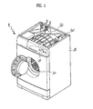
Figure 1 shows a perspective diagram of a drum type laundry machine provided with steam generation according to the present invention; -
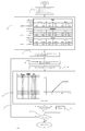
Figure 2 shows a flow chart of a method for controlling the amount of generated steam in a fabric treating appliance provided with steam generation according to a first embodiment of the present invention; -
Figure 3 shows a flow chart of a method for controlling the amount of generated steam in a fabric treating appliance provided with steam generation according to a second embodiment; and -
Figure 4 shows a flow chart of a method for controlling the amount of generated steam in a fabric treating appliance provided with steam generation according to a third embodiment. - With reference initially to
Figure 1 , the present invention will be described, by way of non-limiting examples, with reference to a laundry machine provided with steam generation, in particular for providing it with refreshing/de-wrinkling cycles capability. It will be apparent to the one skilled in the art that the same inventive concept can be applied also to different fabric treating appliance such as washing machines, clothes dryers, fabric refreshing machines and the like in order to heat water, heat a load of fabric items, removing odors therefrom, sanitize them, sanitize components of the fabric treatment appliance and so on. Alternatively or in addition, the steam is provided for the washing cycle itself. - More particularly, a
laundry machine 1 according to the present invention comprises acabinet 10 configuring an exterior of the laundry machine, atub 20, for example a cylindrical one horizontally supported within thecabinet 10 to store water therein, adrum 30 for holding fabric items, rotatably provided within thetub 20 and having preferably perforated holes (not shown in the drawing) for enabling water and steam to be introduced into thedrum 30, a driving motor (also not shown) for driving thedrum 30, and at least onesteam generator 50 for supplying steam into thedrum 30. - The above elements included in the
laundry machine 1 are considered to be known in the art and they will be therefore not further detailed in the following. - It is to be understood that the invention is applicable to any type of
steam generator 50, although a specific embodiment will be described below. - As an example, according to a possible preferred embodiment, the
steam generator 50 is a tank-type steam generator, storing a volume of water and heating it by an heater (not shown) in order to convert the water to steam. Alternatively, according to a different embodiment of the invention, thesteam generator 50 may be an in-line steam generator, such as the one described inU.S. patent application Ser. No. 11/848,550 "Fabric Treatment appliance with steam generator having a variable thermal output", that converts the water to steam as the former flows through the steam generator. - Other examples of steam generators which might be used in the present invention in an alternative manner are disclosed in
U.S. patent application Ser. No. 11/464,528 , titled "Removal of Scale and Sludge in a Steam Generator of a Fabric Treatment Appliance,"U.S. patent application Ser. No. 11/450,836 , titled "Prevention of Scale and Sludge in a Steam Generator of a Fabric Treatment Appliance," orU.S. patent application Ser. No. 11/450,714 U.S. patent application Ser. No. 11/464,509 , titled "Water Supply Control for a Steam Generator of a Fabric Treatment Appliance,"U.S. patent application Ser. No. 11/464,514 , titled "Water Supply Control for a Steam Generator of a Fabric Treatment Appliance Using a Weight Sensor," orU.S. patent application Ser. No. 11/464,513 , titled "Water Supply Control for a Steam Generator of a Fabric Treatment Appliance Using a Temperature Sensor". - In addition, the
laundry machine 1 further comprises acontrol panel 40 connected to a respective control unit (not shown) for allowing the user to input different parameters of washing and, in particular, steaming cycles, as will be better described in the following. Also, the control unit is associated to a processing unit and a storage medium (both not shown) such as an EPROM memory or any other electronic non-volatile memory capable of storing information relating to the washing and steaming cycles. - With reference now to
Figure 2 , a flow chart shows a method for controlling the amount of generated steam in thelaundry machine 1 provided withsteam generator 50 according to the present embodiment. - In particular, the method comprises a first step S1 of inputting specific conditions and parameters of the desired steam cycle to be performed by the
laundry machine 1. More precisely, by means of thecontrol panel 40, a user can select a plurality of different parameters, which will be called in the following, globally, "user's inputs". The available possibilities comprise: - Selection of the "strength" of desired steam cycle (e.g. a light, medium or heavy steam cycle);
- Selection of the amount of fabric load to be treated in the machine (e.g. very low, low, medium load);
- Selection of the type of textile (e.g. cotton, synthetics, etc.) in which the loaded items are realized.
- It is to be understood that only some of the above listed user's inputs as well as additional inputs not listed can be selected via the
control panel 40 by the user. For example the amount of load can be automatically determined by a load sensor positioned in themachine 1 and therefore there is no need that this value is inputted by the user. Alternatively, a torque sensor can be used for the same purpose. Setting the above user's inputs results in a selection of a desired steam cycle. - Furthermore, still in the first step S1 of the method of the invention, a control time tc is also defined. tc represents the sampling rate at which the amount of water evaporated by the steam is measured, as will be better described in the following. It should be noted that this parameter is preferably not inputted by the user, but it is determined in advance during the setup of the laundry machine, i.e. when the laundry machine is installed at the user's home it is already fixed and stored in the same.
- Next, in step S2, a total amount of water to be evaporated in the whole steaming cycle on the basis of the above-mentioned user's inputs is calculated. For this purpose, a Table T1, correlating amounts of water to be evaporated to the specific selected user's inputs of the desired steam cycle, is stored in the storage medium. This Table is obtained by means of several field tests which have been performed on all models of appliance including a steam generator according to the invention and have been preferably realized on the premises of the Applicants when the various appliances are built. The Table is "machine dependent" and - even for the same model - it can differ due to the fact that the same model is sold in different countries having different requirements or preferences. Therefore, Table 1 depends, among others, on the machine model and on the market in which the
machine 1 is distributed. Given the selected user's inputs corresponding to a desired steam cycle as indicated above, stored Table T1 is looked up in order to retrieve from the same a threshold value of evaporated water EWth corresponding to the total amount of water that has to be evaporated in order to achieve the selected steam cycle. - As already mentioned, the threshold values EWth stored in Table is determined experimentally, and it may depend on the specific design of the laundry machine, therefore a given model of appliance may have stored a Table T1 including different values than another appliance's model or appliance for another market.
- Within the same Table 1, according to the different user's inputs, different amounts of water to be transformed in steam can be required. By way of example, as can be seen in Table T1, a light steam cycle, with a low load of synthetics, will require a lower amount of water to be evaporated than a heavy steam cycle with a medium load of cotton.
- It should be also noted that other additional parameters, such as the hardness of water present in the region where the appliance has to be installed, can be taken into account in order to define such threshold values EWth and they can be for example selected during the appliance's set up.
- Once the threshold value EWth has been determined from the user's inputs via the look up Table T1, the steam cycle starts in step S3. In more detail, in step S3 the control unit activates the heater of the
steam generator 50 in order to produce steam which is supplied to thedrum 30. At the same time, the control unit initializes a variable EW which defines the total amount of evaporated water EW at a given point in time during the steaming cycle, which is set equal to 0 at the beginning of the cycle itself. - It should be noted that the total amount of water evaporated in a specific time interval during the steam cycle depends theoretically substantially only on the power/energy provided thereto, which corresponds to the power absorbed by the heater. However, not all the power provided to the appliance is used to heat water: there are intrinsic losses and thermal inertia that prevents to make a one-to-one correspondence between the power and the total amount of water evaporated. In order to solve this problem, in the
machine 1 of the invention, given a steamer system, i.e. given the characteristics of the laundry machine, it is possible to evaluate a characteristic function or, alternatively, a look-up Table T2, correlating the root mean square (RMS) of the current IRMS or voltage VRMS of the AC power of the mains or alternatively the peak voltage of the mains to a corresponding amount of evaporated water. - Therefore, it is possible for the control unit to calculate in a very precise way the amount of water actually evaporated.
- In particular, with reference to the present embodiment, the method according to the present invention comprises a step S4 wherein the control unit measures an average RMS voltage value VRMSc applied to the heater of the steam generator, during for example the same control time tc previously defined. To this purpose, the laundry machine according to the present invention comprises a voltmeter or any other voltage measuring device operatively connected to the control unit. However, also another parameter can be measured for example by detecting the current applied to the heater and then calculating its RMS, IRMSc, as long as such a value is available to the control unit.
- Still with reference to
Figure 2 , once the average RMS voltage value VRMSc applied to the heater is determined via the experimental measure, in step S5 of the method of the invention, using the look-up Table T2, the amount of water EWc evaporated during said time interval tc. is determined in the control unit. Indeed, Table T2 correlates respective values of VRMSc to partial amounts of the amount of water EWc evaporated in a given interval. Also additional and/or different parameters can be considered in order to make a one-to-one correlation between such a parameter and the evaporated water, for example by considering the peak voltage value of the mains. - After each time interval tc, the actual value of total amount of evaporated water EW which has evaporated since the beginning of the steaming cycle, EW, which was initially set to 0 at the beginning of the cycle, is increased of the partial amounts of evaporated water EWc determined according to the mean voltage value measured during the time interval tc and using Table T2.
- Then, the actual value of total amount of evaporated water EW is compared with the threshold value EWth previously determined according to the user's inputs in step S8.
- If the actual value of total amount of evaporated water EW has reached the threshold value EWth, then a heater controller connected to said control unit turns off the heater of the steam generation, thus terminating the steam cycle.
- Otherwise, if the actual value of total amount of evaporated water EW is lower than the threshold value EWth, i.e. it is lower than the amount of water that has to be evaporated according to the user inputs, then step S4 is repeated so that the control unit measures a new average RMS voltage VRMSc in a successive time interval tc+1 and calculate a new amount of evaporated water EW c+1 in this interval. Generally, the average RMS voltage VRMSc is variable during the overall steam cycle, as the mains voltage is subjected to considerable oscillations, since a 10% variation from the nominal value is allowed and higher variations are to be expected. As can be seen from Table T2, representing an example of the correspondence between the measured average RMS voltage VRMSc and the amount of evaporated water per minute, a variation from 230 V to 205 V in the average RMS voltage VRMSc, corresponding to about a 10% variation in the voltage value, corresponds to a 30% variation of the amount of evaporated water, thus considerably affecting the amount of evaporated water in different intervals during the steam cycle.
- In addition, different countries have different mains voltages and therefore this has to be taken into account when the calculation of the evaporated water is made, in order to obtain, for example, a "high steam cycle" which is the same in all countries. In the invention, using the Table T2, it is very easy to overcome the difficulty to set up a machine having a steamer performing substantially the same steaming cycles in all cases. It is sufficient to prepare and save different Tables T2 containing the correct correspondence of VRMS and the evaporated water for - among other parameters - the mains of that specific country where the appliance will be distributed. Moreover, the variations of voltage in the mains tolerated in different countries are also different, which again have consequences in the amount of evaporated steam. All these "possible sources of errors" in the correct calculation of the evaporated water are taken into account in the present invention in a simple manner using a Table T2 correlating the evaporated water with the RMS of the voltage/current of the mains at a given "sampling frequency" determined by the choice of tc.
- Accordingly, the control unit by means of the processing unit will determine a new partial amount of evaporated water EWc+1 to be summed to the total of evaporated water EW previously determined. In other words, EW is updated at each interval tc.
- Then, step S8 is repeated checking again if the new total amount of evaporated water EW has reached the threshold value EWth. Again, if the new total amount of evaporated water EW is still lower than the threshold value EWth steps S4 and S5 will be repeated, otherwise the heater is turned off and the cycle is terminated.
- During steam generation, for example after step S5, the control unit preferably, according to an optional step of the method of the invention, also further controls the quantity of water in the
steam generator 50, e.g. the water contained in the tank if a tank-type generator is used. If the water level detected by the control unit is lower than a predetermined level (for example defined by the amount of water required to completely cover the heater) than a refill procedure is performed in step S7. In fact, in case of water shortage in the tank, the amount of generated steam can be lower than the expected one in a given time interval since the heater can be only partially submersed by water. This can also result in malfunction or damage of the heater or other parts in thesteam generator 50, due to overheating. This refill procedure for example consists in opening a water supply valve and it can envisage either a temporary interruption of the steam generation or a continuation thereof. In the latter case, as will be seen in the following with reference to the other embodiments of the present invention, the transient condition determined by the refill operation can be taken into account when determining the partial amount of evaporated water. - From the above, it has been shown that the appliance according to the present invention can provide coherent and consistent steam cycles as the amount of generated steam can be precisely calculated since it is directly connected to the RMS voltage. In fact, by selecting a suitable sampling rate for measuring the partial amount of evaporated water, it possible to finely control the steam cycle by precisely determining the total amount of evaporated water. By measuring a plurality of partial amounts of evaporated water EWc according to a suitable sampling rate (e.g. each 1 sec., 1 min., etc) it is possible to obtain a very precise total amount of evaporated water, taking into accounts variations of steam generation during the cycle. It should also be noted that the sampling rate - and, accordingly, the selected time intervals - can vary during the steam cycle, being shorter during particular phases of the cycle when a more precise control is required. In fact, the shorter the time intervals are, the more reliable the control of generated steam is.
- Furthermore, Table T1 and Table T2 can be easily obtained as their values can be determined experimentally. In particular, as previously mentioned, Table T1 can be obtained by experimentally determining the amount of steam required for a suitable treating of the fabrics, and Table T2 can be built by means of laboratory tests on the steam generator and on the fabric appliance comprising it.
- In any case, it will be apparent to the one skilled in the art that either Table T1 or Table T2 can be substituted by analytical functions, for example determined by interpolating or fitting the experimental values obtained in the field tests.
- In order to obtain an even more precise control of the steam cycle, it is possible to consider also different parameters affecting the amount of evaporated water during a sampling time. In particular, in
Figures 3 and4 alternative embodiments of the method according to the present invention are described, wherein a new modified Table T2 further considers the variation of the amounts of evaporated water according to different operative phases of the steam generation (Table T2') and according to the evaporated water temperature (Table T2"), respectively. - In the following therefore, with now reference to
figs. 3 and4 , only the modified phase S5 (called phase S5' infig. 3 and phase S5" infig. 4 ) will be described, being the other phases of the method of these two additional embodiments of the invention analogous to the phases already described with reference to the method offig. 2 . - More precisely, with reference to
Figure 3 , a steam generation phase can comprise several operative sub-phases, e.g. a start up (i.e. a cycle initialization), a transient (i.e. the condition during the refill operations) and a working phase. During each phase, the heater operates according to different conditions and the amount of steam produced during such phases is accordingly different: in the start-up period for example the drum and the other parts of the appliance are all rather "cold" therefore a low steam production is expected; in the refill phase on the contrary the appliance's elements are already at a certain "relatively high" temperature (i.e. above room temperature) and therefore a higher production of steam in the same interval is expected. - Therefore, in the embodiment shown in
Figure 3 , Table T2' takes into account different partial amounts of evaporated water on the basis of the steam phase condition, i.e. in which subphase the steamer is working. For example, the control unit can consider start up values for the partial amount of evaporated water during the first minutes of the steam cycles, transient ones when refill of the water tank occurs, and working values in all other cases. More precisely, in this case to a single column of voltage values, three different columns of values of partial amounts of evaporated water EW'c are corresponding namely a first column for the start up the cycle, a second one for a transient phase and a third one for the working phase. Accordingly, in this embodiments, step S5' includes the following: the control unit, after detecting the voltage value VRMSc, looks up the value of partial amount of evaporated water EWc considering the first column during the cycle initialization, the second one during refill operations, and the third one in all other cases. - The update of the evaporated water EW'c is performed as in the previous embodiment continuously updating the value EW'.
- Instead, with reference to
Figure 4 , the correlation between the partial amounts of evaporated water EW"c and the power consumption in this further embodiment also takes into consideration the effect of the temperature in thesteam generator 50. In particular, the amount of evaporated water gradually decreases for temperatures in thesteam generator 50 lower than 100°C, being virtually zero below 80°C. Accordingly, in this embodiment of the method of the invention, the partial amounts of evaporated water are corrected by a function of the temperature f(T) varying from 0 (below 80°C) to 1 (above 100°C) depending on the detected temperature. In particular, as it can be noticed by the graph adjacent to Table T2" and depicted inFigure 4 , the value of the function f(T) varies linearly according to the temperature. According to a different embodiment not shown, also a different dependency can be envisaged. - The method according to the present embodiment of
fig. 4 comprises a further step S9 of detecting the temperature T in thesteam generator 50 before the step S5" can be performed . Then, in step S5" the control unit will look up the value of partial amount of water EW"c in Table T2", first obtaining the value f(T) according to the measured temperature T and then multiplying the value f(T) for a parameter fixed in Table T2" and which depends on the measured VRMSc. - It will be also apparent to the one skilled in the art that the solutions provided in these alternative embodiments can be easily combined thus obtaining an even more precise control of the steam cycle.
Claims (14)
- A fabric treating appliance (1) comprising:a. a steam generator (50) having a heater for evaporating water;b. a control unit apt to calculate partial amounts of evaporated water (EWc) evaporated by said steam generator and measured according to a sampling rate, said control unit comprising a processing unit capable of summing said partial amounts of evaporated water (EWc) in order to obtain an actual value of total amount of evaporated water (EW) by said steam generator at a given time; andc. a heater controller apt to turn off the heater if said actual value of total amount of evaporated water (EW) exceeds a preset threshold value of evaporated water (EWth).
- The appliance (1) according to claim 1, wherein said total amount of evaporated water (EW) is calculated and updated at said sampling rate.
- The appliance (1) according to claim 1 or 2, wherein said partial amounts of evaporated water (EWc) are correlated to respective root means square voltage or current values (VRMSc) of said steam generator (50) measured according to said sampling rate.
- The appliance (1) according to any of the preceding claims, further comprising a storage medium storing a look-up table (T2) correlating said root means square voltage or current values (VRMSc) to said partial amounts of evaporated water (EWc).
- The appliance (1) according to claim 4, wherein said storage medium further store a second look-up Table (T1) correlating a plurality of threshold values of evaporated water (EWth) to respective desired steam cycle, said desired steam cycle being inputted by a user of the appliance.
- The appliance (1) according to any of claim 3 to 6, wherein said steam generation comprises a plurality of different operative phases, said partial amounts of evaporated water (EWc) correlated to said respective root means square voltage or current values varying according to the current operative phase among said operative phases.
- The appliance (1) according to any of claims 3 to 6, wherein said actual values of partial amounts of evaporated water (EWc) correlated to said respective root means square voltage or current values are variable according to a temperature value (T) measured in said steam generator (50).
- A method for controlling the amount of steam generated by a fabric treating appliance (1) provided with steam generation, comprising the steps of:a. defining a sampling rate;b. measuring a partial amount of evaporated water (EWc) according to said sampling rate;c. summing said partial amount of evaporated water (EWc) in order to obtain an actual value of total amount of evaporated water (EW);d. turning off the steam generation if said total amount of evaporated water (EW) exceeds a preset threshold value (EWth) else repeating said steps b and c.
- The method according to claim 8, further comprising a step (S5) of correlating said partial amounts of evaporated water (EWc) to respective root means square voltage or current values measured according to said sampling rate.
- The method according to claim 9, comprising a further step (S3) of measuring the average RMS voltage (VRMSc) applied to the heater of the steam generator (50) during specific time intervals (tc), defined by said sampling rate, in order to determine said power consumption values.
- The method according to claim 10, wherein said steam generation comprises a plurality of different operative phases, said partial amounts of evaporated water (EWc) correlated to said respective root means square voltage or current values varying according to a current operative phase.
- The method according to claim 11, wherein said current operative phase includes a working phase, and/or a refill phase and/or a start-up phase.
- The method according to any of claims 10 or 11, comprising a further step (S4') of measuring a temperature of steam generation (T), said partial amounts of evaporated water (EWc) correlated to said respective root means square voltage or current respective values being variable according to said temperature of steam generation.
- The method according to any of claims 8 to 13, comprising a further steps of inputting a steam treating condition of the fabric and/or a load amount thereof and determining a total amounts of water to be evaporated (EWth) according to the inputted condition and/or load amount.
Priority Applications (1)
| Application Number | Priority Date | Filing Date | Title |
|---|---|---|---|
| EP11165750.8A EP2522768B1 (en) | 2011-05-11 | 2011-05-11 | Fabric treating appliance provided with steam generation and method for controlling the amount of generated steam |
Applications Claiming Priority (1)
| Application Number | Priority Date | Filing Date | Title |
|---|---|---|---|
| EP11165750.8A EP2522768B1 (en) | 2011-05-11 | 2011-05-11 | Fabric treating appliance provided with steam generation and method for controlling the amount of generated steam |
Publications (2)
| Publication Number | Publication Date |
|---|---|
| EP2522768A1 true EP2522768A1 (en) | 2012-11-14 |
| EP2522768B1 EP2522768B1 (en) | 2013-12-18 |
Family
ID=44747055
Family Applications (1)
| Application Number | Title | Priority Date | Filing Date |
|---|---|---|---|
| EP11165750.8A Active EP2522768B1 (en) | 2011-05-11 | 2011-05-11 | Fabric treating appliance provided with steam generation and method for controlling the amount of generated steam |
Country Status (1)
| Country | Link |
|---|---|
| EP (1) | EP2522768B1 (en) |
Cited By (1)
| Publication number | Priority date | Publication date | Assignee | Title |
|---|---|---|---|---|
| CN115016411A (en) * | 2022-06-10 | 2022-09-06 | 苏州益盟新材料科技有限公司 | Water supply management and control system for textile post-processing production line |
Citations (6)
| Publication number | Priority date | Publication date | Assignee | Title |
|---|---|---|---|---|
| EP1507031A1 (en) * | 2003-08-13 | 2005-02-16 | Lg Electronics Inc. | Heating apparatus of washing machine and control method thereof |
| EP1536054A1 (en) * | 2003-11-28 | 2005-06-01 | Dolligkeit Dampf- & Wäschereitechnik KG | Device with at least one work space supplied with steam |
| EP1696067A1 (en) * | 2005-02-25 | 2006-08-30 | LG Electronics, Inc. | Washing machine and control method thereof |
| WO2006101372A1 (en) | 2005-03-25 | 2006-09-28 | Lg Electronics Inc. | Spray steam in drum type washer and control method |
| EP1873297A2 (en) | 2006-06-30 | 2008-01-02 | LG Electronics Inc. | Laundry machine and method of controlling steam generator thereof |
| US20090056389A1 (en) | 2007-08-31 | 2009-03-05 | Whirlpool Corporation | Fabric Treatment Appliance with Steam Generator Having a Variable Thermal Output |
-
2011
- 2011-05-11 EP EP11165750.8A patent/EP2522768B1/en active Active
Patent Citations (6)
| Publication number | Priority date | Publication date | Assignee | Title |
|---|---|---|---|---|
| EP1507031A1 (en) * | 2003-08-13 | 2005-02-16 | Lg Electronics Inc. | Heating apparatus of washing machine and control method thereof |
| EP1536054A1 (en) * | 2003-11-28 | 2005-06-01 | Dolligkeit Dampf- & Wäschereitechnik KG | Device with at least one work space supplied with steam |
| EP1696067A1 (en) * | 2005-02-25 | 2006-08-30 | LG Electronics, Inc. | Washing machine and control method thereof |
| WO2006101372A1 (en) | 2005-03-25 | 2006-09-28 | Lg Electronics Inc. | Spray steam in drum type washer and control method |
| EP1873297A2 (en) | 2006-06-30 | 2008-01-02 | LG Electronics Inc. | Laundry machine and method of controlling steam generator thereof |
| US20090056389A1 (en) | 2007-08-31 | 2009-03-05 | Whirlpool Corporation | Fabric Treatment Appliance with Steam Generator Having a Variable Thermal Output |
Cited By (1)
| Publication number | Priority date | Publication date | Assignee | Title |
|---|---|---|---|---|
| CN115016411A (en) * | 2022-06-10 | 2022-09-06 | 苏州益盟新材料科技有限公司 | Water supply management and control system for textile post-processing production line |
Also Published As
| Publication number | Publication date |
|---|---|
| EP2522768B1 (en) | 2013-12-18 |
Similar Documents
| Publication | Publication Date | Title |
|---|---|---|
| US8037565B2 (en) | Method for detecting abnormality in a fabric treatment appliance having a steam generator | |
| US7966683B2 (en) | Method for operating a steam generator in a fabric treatment appliance | |
| EP1746196B1 (en) | Washing method in steam injection type washing machine | |
| RU2304646C2 (en) | Method for washing of cloths in drum-type washing machine (versions) | |
| US9732460B2 (en) | Fabric treatment appliance control panel and associated steam operations | |
| US8176798B2 (en) | Method and apparatus for determining laundry load | |
| US8601625B2 (en) | Method for controlling the generation of suds in a washing machine and a washing machine suitable therefor | |
| US7905119B2 (en) | Fabric treatment appliance with steam generator having a variable thermal output | |
| US20100287709A1 (en) | Appliance with water hardness determination | |
| US11725326B2 (en) | Fabric cleaning appliance with performance enhancement selector | |
| US7918109B2 (en) | Fabric Treatment appliance with steam generator having a variable thermal output | |
| EP1896640A1 (en) | Control method for time display in drum type washer by spray steam | |
| KR20090079560A (en) | Laundry equipment with steam generator | |
| US7861343B2 (en) | Method for operating a steam generator in a fabric treatment appliance | |
| CN101583754B (en) | Method for washing laundry in a program-controlled domestic appliance, and corresponding domestic appliance | |
| EP2522768B1 (en) | Fabric treating appliance provided with steam generation and method for controlling the amount of generated steam | |
| RU2354768C2 (en) | Method for control of laundry washer | |
| CN104704156A (en) | Method for washing laundry items in a program-controlled domestic appliance, and such a domestic appliance | |
| US20060010611A1 (en) | Washing machine water level controller | |
| EP3973097A1 (en) | Washing machine and control method thereof | |
| WO2008080786A1 (en) | A washer/dryer | |
| WO2013098008A1 (en) | A washer with reduced energy consumption expense | |
| EP0838546A1 (en) | Process for washing with a washing machine, or the like and washing machine for implementing the said process | |
| EP3339490B1 (en) | Method for treating textile articles in a laundry washing machine and laundry washing machine configured to implement the method | |
| WO2016206722A1 (en) | Power supply regulation in laundry treatment machines or dishwashers |
Legal Events
| Date | Code | Title | Description |
|---|---|---|---|
| PUAI | Public reference made under article 153(3) epc to a published international application that has entered the european phase |
Free format text: ORIGINAL CODE: 0009012 |
|
| AK | Designated contracting states |
Kind code of ref document: A1 Designated state(s): AL AT BE BG CH CY CZ DE DK EE ES FI FR GB GR HR HU IE IS IT LI LT LU LV MC MK MT NL NO PL PT RO RS SE SI SK SM TR |
|
| AX | Request for extension of the european patent |
Extension state: BA ME |
|
| 17P | Request for examination filed |
Effective date: 20130514 |
|
| GRAP | Despatch of communication of intention to grant a patent |
Free format text: ORIGINAL CODE: EPIDOSNIGR1 |
|
| INTG | Intention to grant announced |
Effective date: 20130711 |
|
| GRAS | Grant fee paid |
Free format text: ORIGINAL CODE: EPIDOSNIGR3 |
|
| GRAA | (expected) grant |
Free format text: ORIGINAL CODE: 0009210 |
|
| AK | Designated contracting states |
Kind code of ref document: B1 Designated state(s): AL AT BE BG CH CY CZ DE DK EE ES FI FR GB GR HR HU IE IS IT LI LT LU LV MC MK MT NL NO PL PT RO RS SE SI SK SM TR |
|
| REG | Reference to a national code |
Ref country code: GB Ref legal event code: FG4D |
|
| REG | Reference to a national code |
Ref country code: CH Ref legal event code: EP |
|
| REG | Reference to a national code |
Ref country code: AT Ref legal event code: REF Ref document number: 645704 Country of ref document: AT Kind code of ref document: T Effective date: 20140115 |
|
| REG | Reference to a national code |
Ref country code: IE Ref legal event code: FG4D |
|
| REG | Reference to a national code |
Ref country code: DE Ref legal event code: R096 Ref document number: 602011004206 Country of ref document: DE Effective date: 20140213 |
|
| REG | Reference to a national code |
Ref country code: NL Ref legal event code: VDEP Effective date: 20131218 |
|
| PG25 | Lapsed in a contracting state [announced via postgrant information from national office to epo] |
Ref country code: NO Free format text: LAPSE BECAUSE OF FAILURE TO SUBMIT A TRANSLATION OF THE DESCRIPTION OR TO PAY THE FEE WITHIN THE PRESCRIBED TIME-LIMIT Effective date: 20140318 Ref country code: SE Free format text: LAPSE BECAUSE OF FAILURE TO SUBMIT A TRANSLATION OF THE DESCRIPTION OR TO PAY THE FEE WITHIN THE PRESCRIBED TIME-LIMIT Effective date: 20131218 Ref country code: FI Free format text: LAPSE BECAUSE OF FAILURE TO SUBMIT A TRANSLATION OF THE DESCRIPTION OR TO PAY THE FEE WITHIN THE PRESCRIBED TIME-LIMIT Effective date: 20131218 Ref country code: HR Free format text: LAPSE BECAUSE OF FAILURE TO SUBMIT A TRANSLATION OF THE DESCRIPTION OR TO PAY THE FEE WITHIN THE PRESCRIBED TIME-LIMIT Effective date: 20131218 Ref country code: LT Free format text: LAPSE BECAUSE OF FAILURE TO SUBMIT A TRANSLATION OF THE DESCRIPTION OR TO PAY THE FEE WITHIN THE PRESCRIBED TIME-LIMIT Effective date: 20131218 |
|
| REG | Reference to a national code |
Ref country code: AT Ref legal event code: MK05 Ref document number: 645704 Country of ref document: AT Kind code of ref document: T Effective date: 20131218 |
|
| REG | Reference to a national code |
Ref country code: LT Ref legal event code: MG4D |
|
| PG25 | Lapsed in a contracting state [announced via postgrant information from national office to epo] |
Ref country code: RS Free format text: LAPSE BECAUSE OF FAILURE TO SUBMIT A TRANSLATION OF THE DESCRIPTION OR TO PAY THE FEE WITHIN THE PRESCRIBED TIME-LIMIT Effective date: 20131218 Ref country code: LV Free format text: LAPSE BECAUSE OF FAILURE TO SUBMIT A TRANSLATION OF THE DESCRIPTION OR TO PAY THE FEE WITHIN THE PRESCRIBED TIME-LIMIT Effective date: 20131218 |
|
| PG25 | Lapsed in a contracting state [announced via postgrant information from national office to epo] |
Ref country code: IS Free format text: LAPSE BECAUSE OF FAILURE TO SUBMIT A TRANSLATION OF THE DESCRIPTION OR TO PAY THE FEE WITHIN THE PRESCRIBED TIME-LIMIT Effective date: 20140418 Ref country code: EE Free format text: LAPSE BECAUSE OF FAILURE TO SUBMIT A TRANSLATION OF THE DESCRIPTION OR TO PAY THE FEE WITHIN THE PRESCRIBED TIME-LIMIT Effective date: 20131218 Ref country code: BE Free format text: LAPSE BECAUSE OF FAILURE TO SUBMIT A TRANSLATION OF THE DESCRIPTION OR TO PAY THE FEE WITHIN THE PRESCRIBED TIME-LIMIT Effective date: 20131218 |
|
| PG25 | Lapsed in a contracting state [announced via postgrant information from national office to epo] |
Ref country code: SK Free format text: LAPSE BECAUSE OF FAILURE TO SUBMIT A TRANSLATION OF THE DESCRIPTION OR TO PAY THE FEE WITHIN THE PRESCRIBED TIME-LIMIT Effective date: 20131218 Ref country code: ES Free format text: LAPSE BECAUSE OF FAILURE TO SUBMIT A TRANSLATION OF THE DESCRIPTION OR TO PAY THE FEE WITHIN THE PRESCRIBED TIME-LIMIT Effective date: 20131218 Ref country code: PL Free format text: LAPSE BECAUSE OF FAILURE TO SUBMIT A TRANSLATION OF THE DESCRIPTION OR TO PAY THE FEE WITHIN THE PRESCRIBED TIME-LIMIT Effective date: 20131218 Ref country code: NL Free format text: LAPSE BECAUSE OF FAILURE TO SUBMIT A TRANSLATION OF THE DESCRIPTION OR TO PAY THE FEE WITHIN THE PRESCRIBED TIME-LIMIT Effective date: 20131218 Ref country code: CY Free format text: LAPSE BECAUSE OF FAILURE TO SUBMIT A TRANSLATION OF THE DESCRIPTION OR TO PAY THE FEE WITHIN THE PRESCRIBED TIME-LIMIT Effective date: 20131218 Ref country code: CZ Free format text: LAPSE BECAUSE OF FAILURE TO SUBMIT A TRANSLATION OF THE DESCRIPTION OR TO PAY THE FEE WITHIN THE PRESCRIBED TIME-LIMIT Effective date: 20131218 Ref country code: RO Free format text: LAPSE BECAUSE OF FAILURE TO SUBMIT A TRANSLATION OF THE DESCRIPTION OR TO PAY THE FEE WITHIN THE PRESCRIBED TIME-LIMIT Effective date: 20131218 Ref country code: AT Free format text: LAPSE BECAUSE OF FAILURE TO SUBMIT A TRANSLATION OF THE DESCRIPTION OR TO PAY THE FEE WITHIN THE PRESCRIBED TIME-LIMIT Effective date: 20131218 Ref country code: PT Free format text: LAPSE BECAUSE OF FAILURE TO SUBMIT A TRANSLATION OF THE DESCRIPTION OR TO PAY THE FEE WITHIN THE PRESCRIBED TIME-LIMIT Effective date: 20140418 |
|
| REG | Reference to a national code |
Ref country code: DE Ref legal event code: R097 Ref document number: 602011004206 Country of ref document: DE |
|
| PLBE | No opposition filed within time limit |
Free format text: ORIGINAL CODE: 0009261 |
|
| STAA | Information on the status of an ep patent application or granted ep patent |
Free format text: STATUS: NO OPPOSITION FILED WITHIN TIME LIMIT |
|
| PG25 | Lapsed in a contracting state [announced via postgrant information from national office to epo] |
Ref country code: DK Free format text: LAPSE BECAUSE OF FAILURE TO SUBMIT A TRANSLATION OF THE DESCRIPTION OR TO PAY THE FEE WITHIN THE PRESCRIBED TIME-LIMIT Effective date: 20131218 |
|
| 26N | No opposition filed |
Effective date: 20140919 |
|
| PG25 | Lapsed in a contracting state [announced via postgrant information from national office to epo] |
Ref country code: LU Free format text: LAPSE BECAUSE OF FAILURE TO SUBMIT A TRANSLATION OF THE DESCRIPTION OR TO PAY THE FEE WITHIN THE PRESCRIBED TIME-LIMIT Effective date: 20140511 |
|
| REG | Reference to a national code |
Ref country code: CH Ref legal event code: PL Ref country code: DE Ref legal event code: R097 Ref document number: 602011004206 Country of ref document: DE Effective date: 20140919 |
|
| PG25 | Lapsed in a contracting state [announced via postgrant information from national office to epo] |
Ref country code: CH Free format text: LAPSE BECAUSE OF NON-PAYMENT OF DUE FEES Effective date: 20140531 Ref country code: LI Free format text: LAPSE BECAUSE OF NON-PAYMENT OF DUE FEES Effective date: 20140531 Ref country code: MC Free format text: LAPSE BECAUSE OF FAILURE TO SUBMIT A TRANSLATION OF THE DESCRIPTION OR TO PAY THE FEE WITHIN THE PRESCRIBED TIME-LIMIT Effective date: 20131218 |
|
| REG | Reference to a national code |
Ref country code: IE Ref legal event code: MM4A |
|
| PG25 | Lapsed in a contracting state [announced via postgrant information from national office to epo] |
Ref country code: IE Free format text: LAPSE BECAUSE OF NON-PAYMENT OF DUE FEES Effective date: 20140511 |
|
| PG25 | Lapsed in a contracting state [announced via postgrant information from national office to epo] |
Ref country code: SI Free format text: LAPSE BECAUSE OF FAILURE TO SUBMIT A TRANSLATION OF THE DESCRIPTION OR TO PAY THE FEE WITHIN THE PRESCRIBED TIME-LIMIT Effective date: 20131218 |
|
| PG25 | Lapsed in a contracting state [announced via postgrant information from national office to epo] |
Ref country code: MT Free format text: LAPSE BECAUSE OF FAILURE TO SUBMIT A TRANSLATION OF THE DESCRIPTION OR TO PAY THE FEE WITHIN THE PRESCRIBED TIME-LIMIT Effective date: 20131218 |
|
| PG25 | Lapsed in a contracting state [announced via postgrant information from national office to epo] |
Ref country code: SM Free format text: LAPSE BECAUSE OF FAILURE TO SUBMIT A TRANSLATION OF THE DESCRIPTION OR TO PAY THE FEE WITHIN THE PRESCRIBED TIME-LIMIT Effective date: 20131218 |
|
| REG | Reference to a national code |
Ref country code: FR Ref legal event code: PLFP Year of fee payment: 6 |
|
| PG25 | Lapsed in a contracting state [announced via postgrant information from national office to epo] |
Ref country code: BG Free format text: LAPSE BECAUSE OF FAILURE TO SUBMIT A TRANSLATION OF THE DESCRIPTION OR TO PAY THE FEE WITHIN THE PRESCRIBED TIME-LIMIT Effective date: 20131218 Ref country code: GR Free format text: LAPSE BECAUSE OF FAILURE TO SUBMIT A TRANSLATION OF THE DESCRIPTION OR TO PAY THE FEE WITHIN THE PRESCRIBED TIME-LIMIT Effective date: 20140319 |
|
| PG25 | Lapsed in a contracting state [announced via postgrant information from national office to epo] |
Ref country code: TR Free format text: LAPSE BECAUSE OF FAILURE TO SUBMIT A TRANSLATION OF THE DESCRIPTION OR TO PAY THE FEE WITHIN THE PRESCRIBED TIME-LIMIT Effective date: 20131218 Ref country code: HU Free format text: LAPSE BECAUSE OF FAILURE TO SUBMIT A TRANSLATION OF THE DESCRIPTION OR TO PAY THE FEE WITHIN THE PRESCRIBED TIME-LIMIT; INVALID AB INITIO Effective date: 20110511 |
|
| PGFP | Annual fee paid to national office [announced via postgrant information from national office to epo] |
Ref country code: GB Payment date: 20160520 Year of fee payment: 6 |
|
| PGFP | Annual fee paid to national office [announced via postgrant information from national office to epo] |
Ref country code: FR Payment date: 20160520 Year of fee payment: 6 |
|
| GBPC | Gb: european patent ceased through non-payment of renewal fee |
Effective date: 20170511 |
|
| REG | Reference to a national code |
Ref country code: FR Ref legal event code: ST Effective date: 20180131 |
|
| PG25 | Lapsed in a contracting state [announced via postgrant information from national office to epo] |
Ref country code: GB Free format text: LAPSE BECAUSE OF NON-PAYMENT OF DUE FEES Effective date: 20170511 |
|
| PG25 | Lapsed in a contracting state [announced via postgrant information from national office to epo] |
Ref country code: FR Free format text: LAPSE BECAUSE OF NON-PAYMENT OF DUE FEES Effective date: 20170531 |
|
| PG25 | Lapsed in a contracting state [announced via postgrant information from national office to epo] |
Ref country code: MK Free format text: LAPSE BECAUSE OF FAILURE TO SUBMIT A TRANSLATION OF THE DESCRIPTION OR TO PAY THE FEE WITHIN THE PRESCRIBED TIME-LIMIT Effective date: 20131218 |
|
| PG25 | Lapsed in a contracting state [announced via postgrant information from national office to epo] |
Ref country code: AL Free format text: LAPSE BECAUSE OF FAILURE TO SUBMIT A TRANSLATION OF THE DESCRIPTION OR TO PAY THE FEE WITHIN THE PRESCRIBED TIME-LIMIT Effective date: 20131218 |
|
| PGFP | Annual fee paid to national office [announced via postgrant information from national office to epo] |
Ref country code: IT Payment date: 20230525 Year of fee payment: 13 |
|
| P01 | Opt-out of the competence of the unified patent court (upc) registered |
Effective date: 20230625 |
|
| PG25 | Lapsed in a contracting state [announced via postgrant information from national office to epo] |
Ref country code: IT Free format text: LAPSE BECAUSE OF NON-PAYMENT OF DUE FEES Effective date: 20240511 |
|
| PGFP | Annual fee paid to national office [announced via postgrant information from national office to epo] |
Ref country code: DE Payment date: 20250528 Year of fee payment: 15 |