EP2522761A1 - Fluorine gas generation apparatus - Google Patents
Fluorine gas generation apparatus Download PDFInfo
- Publication number
- EP2522761A1 EP2522761A1 EP10842154A EP10842154A EP2522761A1 EP 2522761 A1 EP2522761 A1 EP 2522761A1 EP 10842154 A EP10842154 A EP 10842154A EP 10842154 A EP10842154 A EP 10842154A EP 2522761 A1 EP2522761 A1 EP 2522761A1
- Authority
- EP
- European Patent Office
- Prior art keywords
- gas
- nitrogen
- hydrogen fluoride
- fluorine
- fluorine gas
- Prior art date
- Legal status (The legal status is an assumption and is not a legal conclusion. Google has not performed a legal analysis and makes no representation as to the accuracy of the status listed.)
- Withdrawn
Links
Images


Classifications
-
- C—CHEMISTRY; METALLURGY
- C25—ELECTROLYTIC OR ELECTROPHORETIC PROCESSES; APPARATUS THEREFOR
- C25B—ELECTROLYTIC OR ELECTROPHORETIC PROCESSES FOR THE PRODUCTION OF COMPOUNDS OR NON-METALS; APPARATUS THEREFOR
- C25B1/00—Electrolytic production of inorganic compounds or non-metals
- C25B1/01—Products
- C25B1/24—Halogens or compounds thereof
- C25B1/245—Fluorine; Compounds thereof
-
- C—CHEMISTRY; METALLURGY
- C25—ELECTROLYTIC OR ELECTROPHORETIC PROCESSES; APPARATUS THEREFOR
- C25B—ELECTROLYTIC OR ELECTROPHORETIC PROCESSES FOR THE PRODUCTION OF COMPOUNDS OR NON-METALS; APPARATUS THEREFOR
- C25B9/00—Cells or assemblies of cells; Constructional parts of cells; Assemblies of constructional parts, e.g. electrode-diaphragm assemblies; Process-related cell features
- C25B9/01—Electrolytic cells characterised by shape or form
- C25B9/015—Cylindrical cells
-
- B—PERFORMING OPERATIONS; TRANSPORTING
- B01—PHYSICAL OR CHEMICAL PROCESSES OR APPARATUS IN GENERAL
- B01D—SEPARATION
- B01D5/00—Condensation of vapours; Recovering volatile solvents by condensation
-
- C—CHEMISTRY; METALLURGY
- C01—INORGANIC CHEMISTRY
- C01B—NON-METALLIC ELEMENTS; COMPOUNDS THEREOF; METALLOIDS OR COMPOUNDS THEREOF NOT COVERED BY SUBCLASS C01C
- C01B7/00—Halogens; Halogen acids
- C01B7/19—Fluorine; Hydrogen fluoride
- C01B7/20—Fluorine
-
- C—CHEMISTRY; METALLURGY
- C25—ELECTROLYTIC OR ELECTROPHORETIC PROCESSES; APPARATUS THEREFOR
- C25B—ELECTROLYTIC OR ELECTROPHORETIC PROCESSES FOR THE PRODUCTION OF COMPOUNDS OR NON-METALS; APPARATUS THEREFOR
- C25B1/00—Electrolytic production of inorganic compounds or non-metals
- C25B1/01—Products
- C25B1/24—Halogens or compounds thereof
-
- C—CHEMISTRY; METALLURGY
- C25—ELECTROLYTIC OR ELECTROPHORETIC PROCESSES; APPARATUS THEREFOR
- C25B—ELECTROLYTIC OR ELECTROPHORETIC PROCESSES FOR THE PRODUCTION OF COMPOUNDS OR NON-METALS; APPARATUS THEREFOR
- C25B15/00—Operating or servicing cells
- C25B15/08—Supplying or removing reactants or electrolytes; Regeneration of electrolytes
-
- C—CHEMISTRY; METALLURGY
- C25—ELECTROLYTIC OR ELECTROPHORETIC PROCESSES; APPARATUS THEREFOR
- C25B—ELECTROLYTIC OR ELECTROPHORETIC PROCESSES FOR THE PRODUCTION OF COMPOUNDS OR NON-METALS; APPARATUS THEREFOR
- C25B15/00—Operating or servicing cells
- C25B15/08—Supplying or removing reactants or electrolytes; Regeneration of electrolytes
- C25B15/085—Removing impurities
-
- C—CHEMISTRY; METALLURGY
- C25—ELECTROLYTIC OR ELECTROPHORETIC PROCESSES; APPARATUS THEREFOR
- C25B—ELECTROLYTIC OR ELECTROPHORETIC PROCESSES FOR THE PRODUCTION OF COMPOUNDS OR NON-METALS; APPARATUS THEREFOR
- C25B9/00—Cells or assemblies of cells; Constructional parts of cells; Assemblies of constructional parts, e.g. electrode-diaphragm assemblies; Process-related cell features
-
- F—MECHANICAL ENGINEERING; LIGHTING; HEATING; WEAPONS; BLASTING
- F17—STORING OR DISTRIBUTING GASES OR LIQUIDS
- F17C—VESSELS FOR CONTAINING OR STORING COMPRESSED, LIQUEFIED OR SOLIDIFIED GASES; FIXED-CAPACITY GAS-HOLDERS; FILLING VESSELS WITH, OR DISCHARGING FROM VESSELS, COMPRESSED, LIQUEFIED, OR SOLIDIFIED GASES
- F17C7/00—Methods or apparatus for discharging liquefied, solidified, or compressed gases from pressure vessels, not covered by another subclass
- F17C7/02—Discharging liquefied gases
- F17C7/04—Discharging liquefied gases with change of state, e.g. vaporisation
-
- Y—GENERAL TAGGING OF NEW TECHNOLOGICAL DEVELOPMENTS; GENERAL TAGGING OF CROSS-SECTIONAL TECHNOLOGIES SPANNING OVER SEVERAL SECTIONS OF THE IPC; TECHNICAL SUBJECTS COVERED BY FORMER USPC CROSS-REFERENCE ART COLLECTIONS [XRACs] AND DIGESTS
- Y02—TECHNOLOGIES OR APPLICATIONS FOR MITIGATION OR ADAPTATION AGAINST CLIMATE CHANGE
- Y02E—REDUCTION OF GREENHOUSE GAS [GHG] EMISSIONS, RELATED TO ENERGY GENERATION, TRANSMISSION OR DISTRIBUTION
- Y02E60/00—Enabling technologies; Technologies with a potential or indirect contribution to GHG emissions mitigation
- Y02E60/30—Hydrogen technology
- Y02E60/32—Hydrogen storage
Definitions
- the present invention relates to a fluorine gas generating apparatus.
- JP2004-43885A discloses a fluorine gas generating apparatus provided with an electrolytic cell for electrolyzing hydrogen fluoride in molten salt containing hydrogen fluoride, generating a product gas mainly containing a fluorine gas in a first gas phase section on an anode side, and generating a byproduct gas mainly containing a hydrogen gas in a second gas phase section on a cathode side.
- JP2004-39740A discloses an apparatus which cools a fluorine gas component and components other than the fluorine gas component and separates them by using a difference in a boiling point between the both.
- liquid nitrogen or the like used as a cooling medium is emitted into the atmosphere in a process of refining and is not effectively used.
- the present invention has been made in view of the above problem and has an object of effectively utilizing the cooling medium used in refining of the fluorine gas.
- An aspect of the present invention is a fluorine gas generating apparatus which generates a fluorine gas by electrolyzing hydrogen fluoride in molten salt.
- the fluorine gas generating apparatus includes an electrolytic cell in which the molten salt is retained and which is separated and divided above the liquid level of the molten salt into a first gas chamber into which a product gas mainly containing a fluorine gas generated at an anode immersed in the molten salt is led and a second gas chamber into which a byproduct gas mainly containing a hydrogen gas generated at a cathode immersed in the molten salt is led, and a refining device which refines the fluorine gas by coagulating with a cooling medium and trapping a hydrogen fluoride gas evaporated from the molten salt in the electrolytic cell and mixed in the product gas generated from the anode.
- the cooling medium used for coagulation of the hydrogen fluoride gas in the refining device and discharged is re-used as a utility gas used
- a cooling medium used for coagulation of a hydrogen fluoride gas in a refining device and discharged is re-used as a utility gas used in a spot in the fluorine gas generating apparatus, and thus, the cooling medium used for refining of the fluorine gas can be effectively used.
- a fluorine gas generating apparatus 100 according to the embodiment of the present invention will be described by referring to Fig. 1 .
- the fluorine gas generating apparatus 100 generates a fluorine gas by electrolysis and supplies the generated fluorine gas to an external device 4.
- the external device is a semiconductor manufacturing device, for example, and in that case, the fluorine gas is used as a cleaning gas in a manufacturing process of a semiconductor, for example.
- the fluorine gas generating apparatus 100 includes electrolytic cell 1 which generates a fluorine gas by electrolysis, a fluorine gas supply system 2 which supplies the fluorine gas generated from the electrolytic cell 1 to the external device 4, and a byproduct gas treatment system 3 which treats a byproduct gas generated with the generation of the fluorine gas.
- the electrolytic cell 1 retains molten salt containing hydrogen fluoride (HF).
- HF hydrogen fluoride
- a mixture (KF ⁇ 2HF) of hydrogen fluoride and potassium fluoride (KF) is used as the molten salt.
- the inside of the electrolytic cell 1 is divided by a partition wall 6 immersed in the molten salt to an anode chamber 11 and a cathode chamber 12.
- An anode 7 and a cathode 8 are immersed in the molten salt in the anode chamber 11 and the cathode chamber 12, respectively.
- a product gas mainly containing a fluorine gas (F 2 ) is generated at the anode 7, while a byproduct gas mainly containing a hydrogen gas (H 2 ) is generated at the cathode 8.
- a carbon electrode is used for the anode 7, while soft iron, monel or nickel is used for the cathode 8.
- a first gas chamber 11a into which the fluorine gas generated at the anode 7 is introduced and a second gas chamber 12a into which the hydrogen gas generated at the cathode 8 is led are partitioned by a partition wall 6 from each other so that the gases cannot go out of or come into each other.
- the first gas chamber 11a and the second gas chamber 12a are completely separated by the partition wall 6 in order to prevent reaction by contact between the fluorine gas and the hydrogen gas.
- the molten salt in the anode chamber 11 and the cathode chamber 12 is not separated by the partition wall 6 but communicates with each other below the partition wall 6.
- the melting point of KF ⁇ 2HF is 71.7°C, and thus, the temperature of the molten salt is adjusted to 90 to 100°C.
- Hydrogen fluoride is evaporated from the molten salt by an amount of a vapor pressure and mixed in each of the fluorine gas and the hydrogen gas generated from the anode 7 and the cathode 8 of the electrolytic cell 1.
- a hydrogen fluoride gas is contained in each of the fluorine gas generated at the anode 7 and introduced into the first gas chamber 11a and the hydrogen gas generated at the cathode 8 and introduced into the second gas chamber 12a.
- a liquid level meter 13 which detects a liquid level of the retained molten salt as a liquid level detector is provided.
- the liquid level meter 13 is a back-pressure type liquid level meter which detects a back pressure when a certain flow rate of the nitrogen gas is purged into the molten salt through an insertion pipe 13a inserted into the electrolytic cell 1 and detects a liquid level from the back pressure and a liquid specific weight of the molten salt.
- a first main passage 15 for supplying the fluorine gas to the external device 4 is connected to the first gas chamber 11a.
- a first pump 17 which leads the fluorine gas out of the first gas chamber 11a and conveys it is provided in the first main passage 15.
- a positive-displacement pump such as a bellows pump, a diaphragm pump or the like is used for the first pump 17.
- a refining device 16 for trapping the hydrogen fluoride gas mixed in the product gas and refining the fluorine gas is provided upstream of the first pump 17 in the first main passage 15.
- the refining device 16 is a device for separating and removing the hydrogen fluoride gas from the fluorine gas by using a difference in boiling points between fluorine and hydrogen fluoride.
- the refining device 16 is composed of two systems of a first refining device 16a and a second refining device 16b provided in parallel with each other and they can be switched so that the fluorine gas passes through only either one of the systems. That is, if one of the first refining device 16a and the second refining device 16b is in the operating state, the other is stopped or in the stand-by state.
- the refining device 16 will be described later in detail.
- a first buffer tank 21 which retains the fluorine gas conveyed by the first pump 17 is provided downstream of the first pump 17 in the first main passage 15. The fluorine gas retained in the first buffer tank 21 is supplied to the external device 4.
- a flow meter 26 which detects a flow rate of the fluorine gas supplied to the external device 4 is provided downstream of the first buffer tank 21.
- a power supply 9 controls a current value supplied between the anode 7 and the cathode 8 on the basis of a detection result of the flow meter 26. Specifically, a generation amount of the fluorine gas at the anode 7 is controlled so that the fluorine gas supplied to the external device 4 is replenished.
- control is made so that the fluorine gas supplied to the external device 4 is replenished, and an internal pressure of the first buffer tank 21 is maintained at a pressure higher than the atmospheric pressure.
- the external device 4 side where the fluorine gas is used is at the atmospheric pressure, by opening a value provided in the external device 4, the fluorine gas is supplied from the first buffer tank 21 to the external device 4 due to a pressure difference between the first buffer tank 21 and the external device 4.
- a branch passage 22 is connected to the first buffer tank 21, and the pressure regulating valve 23 which controls the internal pressure of the first buffer tank 21 is provided in the branch passage 22. Moreover, a pressure meter 24 which detects the internal pressure is provided on the first buffer tank 21.
- the pressure regulating valve 23 controls the internal pressure of the first buffer tank 21 so that it does not exceed a predetermined pressure set in advance on the basis of a detection result of the pressure meter 24. Specifically, when the internal pressure of the first buffer tank 21 exceeds 1.0 MPa, the valve is opened so as to discharge the fluorine gas in the first buffer tank 21.
- a second buffer tank 50 which retains the fluorine gas discharged from the first buffer tank 21 is provided downstream of the pressure regulating valve 23 in the branch passage 22. That is, if the internal pressure of the first buffer tank 21 exceeds the predetermined pressure, the fluorine gas in the first buffer tank 21 is discharged through the pressure regulating valve 23, and the discharged fluorine gas is led to the second buffer tank 50.
- the second buffer tank 50 has a capacity smaller than the first buffer tank 21.
- a pressure regulating valve 51 which controls the internal pressure of the second buffer tank 50 is provided downstream of the second buffer tank 50 in the branch passage 22. Moreover, a pressure meter 52 which detects the internal pressure is provided on the second buffer tank 50. The pressure regulating valve 51 controls the internal pressure of the second buffer tank 50 on the basis of a detection result of the pressure meter 52 so that it becomes a predetermined pressure set in advance. The fluorine gas discharged from the second buffer tank 50 through the pressure regulating valve 51 is rendered harmless at an abatement unit 53 and emitted.
- a fluorine gas supply passage 54 which supplies the fluorine gas to the refining device 16 is connected to the second buffer tank 50.
- a second main passage 30 for discharging the hydrogen gas to the outside is connected to the second gas chamber 12a.
- a second pump 31 which leads the hydrogen gas out of the second gas chamber 12a and conveys it is provided in the second main passage 30.
- An abatement unit 34 is provided downstream of the second pump 31 in the second main passage 30, and the hydrogen gas conveyed by the second pump 31 is rendered harmless in the abatement unit 34 and emitted.
- the fluorine gas generating apparatus 100 is also provided with a raw material supply system 5 which supplies hydrogen fluoride which is a raw material of the fluorine gas into the molten salt in the electrolytic cell 1.
- the raw material supply system 5 will be described below.
- the raw material supply system 5 includes a hydrogen fluoride supply source 40 in which hydrogen fluoride to be replenished to the electrolytic cell 1 is retained.
- the hydrogen fluoride supply source 40 and the electrolytic cell 1 are connected through the raw material supply passage 41.
- the hydrogen fluoride retained in the hydrogen fluoride supply source 40 is supplied into the molten salt in the electrolytic cell 1 through the raw material passage 41.
- a flow rate control valve 42 which controls a supply flow rate of hydrogen fluoride is provided in the raw material supply passage 41.
- the flow rate control valve 42 controls the supply flow rate of hydrogen fluoride on the basis of a detection result of the liquid level meter 13 so that the liquid level of the molten salt in the electrolytic cell 1 becomes a predetermined level. That is, the flow rate control valve 42 controls the supply flow rate of hydrogen fluoride so that the electrolyzed hydrogen fluoride in the molten salt is replenished.
- a carrier-gas supply passage 46 which leads a carrier gas supplied from a carrier-gas supply source 45 into the raw material supply passage 41 is connected to the raw material supply passage 41.
- a shut-off valve 47 which switches between supply and shut-off of the carrier gas is provided in the carrier-gas supply passage 46.
- the carrier gas is an entrained gas for leading the hydrogen fluoride retained in the hydrogen fluoride supply source 40 into the molten salt in the electrolytic cell 1, and a nitrogen gas which is an inactive gas is used.
- the shut-off valve 47 is open in principle, and the nitrogen gas is supplied into the molten salt in the cathode chamber 12 of the electrolytic cell 1. The nitrogen gas is hardly dissolved in the molten salt and discharged from the second gas chamber 12a through the byproduct gas treatment system 3.
- the first refining device 16a and the second refining device 16b have the same configuration, the first refining device 16a will be mainly described below, and the same reference numerals are given to the same configurations in the second refining device 16b as those in the first refining device 16a, and the description will be omitted.
- the configurations of the first refining device 16a are suffixed by "a” and the configurations of the second refining device 16b are suffixed by "b" for discrimination.
- the first refining device 16a includes an inner tube 61a as a gas inflow unit into which the fluorine gas containing the hydrogen fluoride gas flows and a cooling device 70a which cools the inner tube 61a at a temperature not lower than the boiling point of fluorine and not higher than the melting point of hydrogen fluoride so that the fluorine gas passes through the inner tube 61a while the hydrogen fluoride gas mixed in the fluorine gas is coagulated.
- the inner tube 61a is a bottomed cylindrical member, and an upper opening thereof is sealed by a lid member 62a.
- An inlet passage 63a which leads the fluorine gas generated in the anode 7 into the inner tube 61a is connected to the lid member 62a of the inner tube 61a.
- the inlet passage 63a is one of two passages branching from the first main passage 15, and the other inlet passage 63b is connected to an inner tube 61b of the second refining device 16b.
- An inlet valve 64a which allows or shuts off inflow of the fluorine gas into the inner tube 61 a is provided in the inlet passage 63a.
- a conduit 67a provided by being suspended into the inner tube 61a is connected to the inner surface of the lid member 62a of the inner tube 61a.
- the conduit 67a is formed to have a length such that a lower end opening portion is located in the vicinity of the bottom part of the inner tube 61 a.
- An upper end portion of the conduit 67a is connected to an outlet passage 65a connected to the lid member 62a and discharging the fluorine gas through the inner tube 61a. Therefore, the fluorine gas in the inner tube 61a flows out to the outside through the conduit 67a and the outlet passage 65a.
- An outlet valve 66a which allows or shuts off outflow of the fluorine gas from the inner tube 61 a is provided in the outlet passage 65a.
- the outlet passage 65a merges with an outlet passage 65b of the second refining device 16b and is connected to the first pump 17.
- the fluorine gas generated in the anode 7 flows into the inner tube 61a through the inlet passage 63a and flows out of the inner tube 61a through the conduit 67a and the outlet passage 65a.
- the inlet valve 64a and the outlet valve 66a are open, while if the first refining device 16a is in the stop or standby state, the inlet valve 64a and the outlet valve 66a are closed.
- thermometer 68a which detects an internal temperature is provided in the inner tube 61 a by being inserted through the lid member 62a. Moreover, a pressure meter 69a which detects the internal pressure of the inner tube 61a is provided in the inlet passage 63a.
- the cooling device 70a includes a jacket tube 71a capable of partially containing the inner tube 61a and capable of retaining liquid nitrogen as a cooling medium therein and a liquid nitrogen supply/discharge system 72a which supplies/discharges liquid nitrogen to/from the jacket tube 71a.
- the jacket tube 71a is a bottomed cylindrical member, and an upper opening portion is sealed by a lid member 73a.
- the inner tube 61a is coaxially contained in the jacket tube 71a in a state having the upper part side protruding from the lid member 73a. Specifically, 80 to 90% of the inner tube 61a is contained in the jacket tube 71a.
- liquid nitrogen supply/discharge system 72a will be described.
- a liquid nitrogen supply passage 77a which leads the liquid nitrogen supplied from a liquid nitrogen supply source 76 into the jacket tube 71a is connected to the lid member 73a of the jacket tube 71a.
- a conduit 82a provided by being suspended into the jacket tube 71a is connected to the inner surface of the lid member 73a of the jacket tube 71a, and an upper end portion of the conduit 82a is connected to the liquid nitrogen supply passage 77a. Therefore, the liquid nitrogen supplied from the liquid nitrogen supply source 76 is led into the jacket tube 71a through the liquid nitrogen supply passage 77a and the conduit 82a.
- the conduit 82a is formed to have a length such that a lower end opening portion is located in the vicinity of the bottom part of the jacket tube 71a.
- a flow rate control valve 78a which controls the supply flow rate of the liquid nitrogen is provided in the liquid nitrogen supply passage 77a.
- a pressure meter 80a which detects an internal pressure of the jacket tube 71a is provided downstream of the flow rate control valve 78a in the liquid nitrogen supply passage 77a.
- the inside of the jacket tube 71a is formed of two layers, that is, the liquid nitrogen and evaporated nitrogen gas, and the liquid level of the liquid nitrogen is detected by a liquid level meter 74a provided by being inserted through the lid member 73a.
- a nitrogen gas discharge passage 79a for discharging the nitrogen gas in the jacket tube 71a is connected to the lid member 73a of the jacket tube 71a.
- a pressure regulating valve 81a which controls the internal pressure of the jacket tube 71a is provided in the nitrogen gas discharge passage 79a.
- the pressure regulating valve 81a executes control such that the internal pressure of the jacket tube 71a becomes a predetermined pressure determined in advance on the basis of a detection result of the pressure meter 80a. This predetermined pressure is determined so that the temperature of the liquid nitrogen in the jacket tube 71a becomes not lower than the boiling point (-188°C) of fluorine and not higher than the melting point (-84°C) of hydrogen fluoride.
- the pressure is set to 0.4 MPa so that the temperature of the liquid nitrogen in the jacket tube 71a becomes approximately -180°C.
- the pressure regulating valve 81a controls the internal pressure of the jacket tube 71a to 0.4 MPa so that the temperature of the liquid nitrogen in the jacket tube 71a is maintained at approximately -180°C.
- the nitrogen gas discharged through the pressure regulating valve 81 a is led to a nitrogen buffer tank 210 (See Fig. 4 ), which will be described later.
- the flow rate control valve 78a controls the supply flow rate of the liquid nitrogen from the liquid nitrogen supply source 76 to the jacket tube 71a on the basis of a detection result of the liquid level meter 74a so that the liquid level of the liquid nitrogen in the jacket tube 71a is maintained constant on the basis of a detection result of the liquid level meter 74a.
- An insulating material or a vacuum insulation layer for heat-retention may be provided outside the jacket tube 71a in order to suppress heat transfer between the jacket tube 71a and the outside.
- the inner tube 61a is cooled by the jacket tube 71a to a temperature not lower than the boiling point of fluorine and not higher than the melting point of hydrogen fluoride, only hydrogen fluoride mixed in the fluorine gas is coagulated in the inner tube 61a, and the fluorine gas passes through the inner tube 61a. Since the fluorine gas is continuously led from the electrolytic cell 1 into the inner tube 61a, the coagulated hydrogen fluoride accumulates in the inner tube 61a as time elapses.
- the operation of the first refining device 16a is stopped, the second refining device 16b in the standby state is started, and operation of the refining device 16 is switched.
- the operation switching will be described later in detail.
- Whether or not the accumulated amount of the coagulated hydrogen fluoride has reached the predetermined amount is determined on the basis of a detection result of a differential pressure meter 86a provided between the inlet passage 63a and the outlet passage 65a of the inner tube 61a, that is, a differential pressure between the inlet and the outlet of the inner tube 61 a. If the differential pressure between the inlet and the outlet of the inner tube 61a reaches the predetermined value, it is determined that the accumulated amount of the coagulated hydrogen fluoride in the inner tube 61a has reached the predetermined amount, and the first refining device 16a is stopped.
- the differential pressure meter 86a corresponds to an accumulated state detector which detects an accumulated state of the hydrogen fluoride in the inner tube 61a.
- the accumulated state of the hydrogen fluoride in the inner tube 61 a may be detected by the pressure meter 69a instead of the differential pressure meter.
- the first refining device 16a is stopped by closing the inlet valve 64a and the outlet valve 66a of the inner tube 61a. After the first refining device 16a is stopped, it is necessary to discharge the coagulated hydrogen fluoride accumulated in the inner tube 61a and to bring the first refining device 16a into the standby state. That is, a regeneration process of the first refining device 16a needs to be performed.
- a liquid nitrogen discharge passage 90a for discharging the liquid nitrogen in the jacket tube 71a is connected to the bottom part of the jacket tube 71a.
- a discharge valve 91a that can discharge the liquid nitrogen in the jacket tube 71a by being opened is provided in the liquid nitrogen discharge passage 90a.
- the liquid nitrogen discharged through the discharge valve 91a is led to the nitrogen buffer tank 210 (See Fig. 4 ).
- a nitrogen gas supply passage 93a which leads the nitrogen gas supplied from a nitrogen gas supply source 92 into the jacket tube 71a is connected to the downstream of the flow rate control valve 78a in the liquid nitrogen supply passage 77a.
- a shut-off valve 94a which switches between supply and shut-off of the nitrogen gas into the jacket tube 71a is provided in the nitrogen gas supply passage 93a.
- the supply of the nitrogen gas from the nitrogen gas supply source 92 to the jacket tube 71 a is performed in a state in which the discharge valve 91 a is fully open and the flow rate control valve 78a is fully closed.
- As the nitrogen gas a gas at a normal temperature is used.
- the nitrogen gas at a normal temperature is supplied therein while liquid nitrogen is discharged.
- the temperature of the inner tube 61a is raised, and the coagulated hydrogen fluoride is dissolved with that.
- a discharge passage 95a for discharging the dissolved hydrogen fluoride to the outside is connected to the downstream of the inlet valve 64a in the inlet passage 63a.
- a discharge pump 96 for suctioning and conveying the dissolved hydrogen fluoride in the jacket tube 71a is provided in the discharge passage 95a, and a discharge valve 97a opened when the hydrogen fluoride is discharged is provided upstream of the discharge pump 96.
- an abatement unit 98 is provided downstream of the discharge pump 96 in the discharge passage 95a, and hydrogen fluoride conveyed by the discharge pump 96 is rendered harmless in the abatement unit 98 and emitted.
- a nitrogen gas supply passage 99a which leads the nitrogen gas supplied from the nitrogen gas supply source 92 into the inner tube 61a is connected to the upstream of the outlet valve 66a in the outlet passage 65a.
- a shut-off valve 87a which switches between supply and shut-off of the nitrogen gas to the inner tube 61a is provided in the nitrogen gas supply passage 99a. The supply of the nitrogen gas from the nitrogen gas supply source 92 to the inner tube 61a is performed in a state in which the discharge valve 97a is fully open and the discharge pump 96 has been started.
- the dissolved hydrogen fluoride is sucked therefrom by the discharge pump 96, while the nitrogen gas at a normal temperature is supplied therein. As a result, the hydrogen fluoride in the inner tube 61a is discharged.
- the discharge from the inner tube 61a by the discharge pump 96 is performed until the internal pressure of the inner tube 61a detected by the pressure meter 69a falls below the atmospheric pressure.
- the hydrogen fluoride in the inner tube 61a discharged by the discharge pump 96 may be re-used by being returned to the hydrogen fluoride supply source 40 or the electrolytic cell 1.
- the fluorine gas is filled into the inner tube 61a. This is done so that the operation can be quickly switched to the first refining device 16a, if the accumulated amount of the coagulated hydrogen fluoride in the inner tube 61a reaches a predetermined amount while the second refining device 16b is operating.
- the filling of the fluorine gas into the inner tube 61 a is performed through the fluorine gas supply passage 54 connected to the second buffer tank 50 and whose downstream end portion is connected to the downstream of the inlet valve 64a in the inlet passage 63a.
- a shut-off valve 88a which opens when the fluorine gas is to be filled into the inner tube 61a is provided in the fluorine gas supply passage 54.
- the internal pressure of the second buffer tank 50 is controlled by the pressure regulating valve 51 to a pressure higher than the atmospheric pressure, and thus, the fluorine gas retained in the second buffer tank 50 is supplied into the inner tube 61a by the differential pressure between the second buffer tank 50 and the inner tube 61a. As described above, the fluorine gas retained in the second buffer tank 50 is used for the filling of the fluorine gas into the inner tube 61a.
- the following operation of the refining device 16 is controlled by a controller (not shown) mounted on the fluorine gas generating apparatus 100.
- the controller controls operations of each valve and each pump on the basis of detection results of the thermometer 68a, the pressure meter 69a, the liquid level meter 74a, the pressure meter 80a, and the differential pressure meter 86a.
- the first refining device 16a is in the operating state and the second refining device 16b is in the standby state.
- the inlet valve 64a and the outlet valve 66a of the inner tube 61a is in the open state, and the fluorine gas is continuously led from the electrolytic cell 1 into the inner tube 61a.
- an inlet valve 64b and an outlet valve 66b of the inner tube 61b are in the closed state, and the fluorine gas is filled in the inner tube 61b.
- the fluorine gas generated in the electrolytic cell 1 is supplied only to the first refining device 16a.
- the liquid nitrogen led through the liquid nitrogen supply passage 77a is retained in the jacket tube 71a of the first refining device 16a, and the inner tube 61a is cooled by the liquid nitrogen.
- the internal pressure of the jacket tube 71a is controlled by the pressure regulating valve 81a to 0.4 MPa.
- the temperature of the liquid nitrogen in the jacket tube 71a is maintained at approximately -180°C which is the temperature not lower than the boiling point of fluorine and not higher than the melting point of hydrogen fluoride, and thus, only the hydrogen fluoride is coagulated in the inner tube 61a, while the fluorine gas passes through the inner tube 61a and is conveyed by the first pump 17 to the first buffer tank 21.
- the fluorine gas generated in the electrolytic cell 1 flows into the inner tube 61a through the inlet passage 63a and flows out through the conduit 67a and the outlet passage 65a.
- a lower end opening portion of the conduit 67a is located in the vicinity of the bottom part of the inner tube 61a, and thus, the fluorine gas flows in from the upper part of the inner tube 61 a and flows out of the lower part of the inner tube 61a. Therefore, the fluorine gas is sufficiently cooled while passing through the inner tube 61a, and thus, hydrogen fluoride in the fluorine gas can be reliably coagulated and the hydrogen fluoride can be completely removed.
- the liquid nitrogen in the jacket tube 71a for cooling the fluorine gas is also continuously evaporated.
- the evaporated nitrogen gas is discharged to the nitrogen buffer tank 210 (See Fig. 4 ) through the nitrogen gas discharge passage 79a.
- the operation of the first refining device 16a is stopped, and the second refining device 16b in the standby state is started so that operation of the refining device 16 is switched.
- the regeneration process is performed after the operation is stopped.
- Fig. 3 is a graph illustrating temporal changes of the pressure and the temperature in the inner tube 61a of the first refining device 16a, in which a solid line indicates the pressure, and a one-dot chain line indicates the temperature.
- the pressure illustrated in Fig. 3 is detected by the pressure meter 69a, and the temperature is detected by the thermometer 68a.
- the internal pressure of the inner tube 6 1 a rises. If the internal pressure of the inner tube 61a reaches the predetermined pressure (Ph) and the differential pressure between the inlet and the outlet of the inner tube 61a detected by the differential pressure meter 86a reaches the predetermined value, the operation is switched from the first refining device 16a to the second refining device 16b (time t1).
- the inlet valve 64b and the outlet valve 66b of the inner tube 61 b of the second refining device 16b are opened, the inlet valve 64a and the outlet valve 66a of the inner tube 61 a of the first refining device 16a are closed.
- the second refining device 16b is started, while the first refining device 16a is stopped, and the fluorine gas from the electrolytic cell 1 is led to the second refining device 16b.
- the liquid nitrogen is discharged from the jacket tube 71a.
- the flow rate control valve 78a of the liquid nitrogen supply passage 77a is fully closed, and the supply of the liquid nitrogen to the jacket tube 71a is stopped and then, the discharge valve 91a is opened, and the liquid nitrogen is discharged to the nitrogen buffer tank 210 (See Fig. 4 ) through the liquid nitrogen discharge passage 90a.
- the pressure regulating valve 81a may be opened so as to lead the nitrogen gas in the nitrogen buffer tank 210 to the jacket tube 71a through the nitrogen gas discharge passage 79a and to promote discharge of the liquid nitrogen in the jacket tube 71a.
- the shut-off valve 94a of the nitrogen gas supply passage 93a is opened, and the nitrogen gas at a normal temperature is supplied to the jacket tube 71a.
- the temperature in the inner tube 61a rises to the normal temperature, and hydrogen fluoride in the inner tube 61a is dissolved.
- the discharge valve 97a of the discharge passage 95a is opened, and the discharge pump 96 is started.
- the dissolved hydrogen fluoride in the inner tube 61 b is sucked by the discharge pump 96 and conveyed to the abatement unit 98.
- the shut-off valve 87a of the nitrogen gas supply passage 99a is opened, and the nitrogen gas at a normal temperature is supplied into the inner tube 61a.
- the dissolved hydrogen fluoride is discharged while the nitrogen gas at a normal temperature is being supplied therein.
- the liquid nitrogen is supplied into the jacket tube 71a so as to bring the first refining device 16a into the standby state, and the fluorine gas is supplied into the inner tube 61b.
- the liquid nitrogen is supplied into the jacket tube 71a (time t3) while the discharge valve 9 1a and the shut-off valve 94a of the nitrogen gas supply passage 93a are fully closed and the flow rate control valve 78a of the liquid nitrogen supply passage 77a is opened again. As a result, the internal temperature of the inner tube 61a is lowered.
- the internal pressure of the jacket tube 71a is controlled by the pressure regulating valve 81a to 0.4 MPa, the internal temperature of the inner tube 61a is lowered to approximately -180°C and maintained.
- the shut-off valve 88a of the fluorine gas supply passage 54 is opened, and the fluorine gas of the second buffer tank 50 is supplied into the inner tube 61a (time t4).
- the internal pressure of the inner tube 61a is raised by the supply of the fluorine gas into the inner tube 61a and when it rises to the atmospheric pressure, the shut-off valve 88a is closed, and the supply of the fluorine gas is stopped.
- the filling of the fluorine gas into the inner tube 61a is performed as above. In this way, the regeneration process of the first refining device 16a is finished, and the first refining device enters the standby state (time t5).
- the fluorine gas of the second buffer tank 50 is used for the fluorine gas supplied into the inner tube 61a during the regeneration process.
- the second buffer tank 50 is a tank for retaining the fluorine gas discharged with control of the internal pressure of the first buffer tank 21. That is, in the regeneration process, the fluorine gas which used to be discharged to the outside from the first buffer tank 21 is retained in the second buffer tank 50 and the retained fluorine gas is used.
- the fluorine gas supplied into the inner tube 61a in the regeneration process the gas having been emitted to the outside is used.
- the first refining device 16a during stop has the inner tube 61a cooled to -180°C and also is in the standby state in which the fluorine gas is filled in the inner tube 61a. Therefore, if the differential pressure between the inlet and the outlet of the inner tube 61b in the second refining device 16b during operation reaches a predetermined value, the operation of the second refining device 16b is stopped and the first refining device 16a is quickly started so that the operation of the refining device 16 can be switched.
- the nitrogen recovery facility 200 recovers the nitrogen gas and the liquid nitrogen used for coagulation of the hydrogen fluoride gas in the cooling devices 70a and 70b of the refining device 16 and discharged and supplies the nitrogen gas as a utility gas used at each spot in the fluorine gas generating apparatus 100.
- the nitrogen recovery facility 200 is provided with the nitrogen buffer tank 210 for recovering the nitrogen gas and the liquid nitrogen used for coagulation of the hydrogen fluoride gas in the cooling devices 70a and 70b of the refining device 16 and discharged and for temporarily storing them.
- the lower ends of the nitrogen gas discharge passages 79a and 79b and the lower ends of the liquid nitrogen discharge passages 90a and 90b are connected. Therefore, in the nitrogen buffer tank 210, the nitrogen gas discharged from the jacket tubes 71a and 71b is recovered through the nitrogen gas discharge passage 79a and 79b, and the liquid nitrogen discharged from the jacket tubes 71a and 71b is recovered through the liquid nitrogen discharge passages 90a and 90b.
- the nitrogen buffer tank 210 is arranged below the jacket tubes 71a and 71 b, and thus, the liquid nitrogen in the jacket tubes 71a and 71 b is discharged by gravity to the nitrogen buffer tank 210 by opening the discharge valves 91 a and 91b of the liquid nitrogen discharge passages 90a and 90b.
- the nitrogen buffer tank 210 may be arranged at the same level as the jacket tubes 71a and 71b or above the jacket tubes 71a and 71b. In that case, in order to discharge the liquid nitrogen in the jacket tubes 71a and 71b into the nitrogen buffer tank 210, pumps need to be provided in the liquid nitrogen discharge passages 90a and 90b.
- the liquid nitrogen in the jacket tubes 71a and 71b may be discharged into the nitrogen buffer tank 210 by pressurizing gas phase parts in the jacket tubes 71a and 71b instead of providing pumps.
- a branch liquid nitrogen supply passage 201 branching from the liquid nitrogen supply passage 77a (See Fig. 2 ) connected to the liquid nitrogen supply source 76 is also connected.
- a flow rate control valve 202 which controls the liquid level of the liquid nitrogen retained in the nitrogen buffer tank 210 to a predetermined level set in advance by controlling the supply flow rate of the liquid nitrogen to the nitrogen buffer tank 210 from the liquid nitrogen supply source 76 is provided.
- the inside of the nitrogen buffer tank 210 is formed of two layers, that is, the liquid nitrogen and the nitrogen gas, and the liquid level of the liquid nitrogen is detected by a liquid level meter 203 as a liquid level detector.
- the flow rate control valve 202 controls the supply flow rate of the liquid nitrogen so that the liquid level of the liquid nitrogen in the nitrogen buffer tank 210 becomes a predetermined level set in advance on the basis of a detection result of the liquid level meter 203.
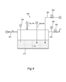
- the nitrogen gas discharge passages 79a and 79b are arranged so that the downstream ends thereof are inserted into the liquid in the nitrogen buffer tank 210, the nitrogen gas recovered through the nitrogen gas discharge passages 79a and 79b is introduced into the liquid, and the liquid level of the liquid nitrogen in the nitrogen buffer tank 210 might roll. Thus, it becomes difficult to detect the liquid level of the liquid nitrogen in the nitrogen buffer tank 210 by the liquid level meter 203 with accuracy. Therefore, the nitrogen gas discharge passages 79a and 79b are, as illustrated in Fig. 4 , preferably arranged so that the nitrogen gas is introduced to the gas phase part of the nitrogen buffer tank 210.
- an emission passage 204 for emitting the internal nitrogen gas to the atmosphere is connected to the nitrogen buffer tank 210.
- a pressure meter 205 which detects an internal pressure of the nitrogen buffer tank 210
- a pressure control valve 206 which controls the internal pressure of the nitrogen buffer tank 210 are provided.
- the pressure control valve 206 executes control so that the internal pressure of the nitrogen buffer tank 210 becomes a predetermined pressure set in advance on the basis of a detection result of the pressure meter 205. Specifically, control is executed so that the internal pressure of the nitrogen buffer tank 210 becomes 0.4 MPa, and if the internal pressure is 0.4 MPa or more, the valve is opened, and the internal nitrogen gas is emitted to the atmosphere through the emission passage 204.
- the nitrogen gas and the liquid nitrogen used for coagulation of the hydrogen fluoride gas in the cooling devices 70a and 70b of the refining device 16 and discharged are recovered in the nitrogen buffer tank 210, and the recovered nitrogen gas and the liquid nitrogen are stored in a state in which the liquid level and the internal pressure of the nitrogen buffer tank 210 are controlled.
- a utility gas supply passage 207 for supplying the internal nitrogen gas as a utility gas used at each spot in the fluorine gas generating apparatus 100 is connected to the nitrogen buffer tank 210.
- the utility gas supply passage 207 is branched into plurality of branches on the way the middle, and the nitrogen gas is used at each spot in the fluorine gas generating apparatus 100.
- the nitrogen gas is used at spots as follows.
- the nitrogen gas and the liquid nitrogen temporarily stored in the nitrogen buffer tank 210 is re-used as a utility gas at each spot in the fluorine gas generating apparatus 100.
- the nitrogen gas and the liquid nitrogen used for coagulation of the hydrogen fluoride gas in the refining device 16 and discharged are not emitted to the outside but re-used as a utility gas used at each spot in the fluorine gas generating apparatus 100. Therefore, the liquid nitrogen used for refining the fluorine gas can be effectively utilized.
Landscapes
- Chemical & Material Sciences (AREA)
- Organic Chemistry (AREA)
- Engineering & Computer Science (AREA)
- Chemical Kinetics & Catalysis (AREA)
- Electrochemistry (AREA)
- Materials Engineering (AREA)
- Metallurgy (AREA)
- Inorganic Chemistry (AREA)
- Mechanical Engineering (AREA)
- General Engineering & Computer Science (AREA)
- Electrolytic Production Of Non-Metals, Compounds, Apparatuses Therefor (AREA)
Abstract
A fluorine gas generating apparatus includes an electrolytic cell where the molten salt is retained and which is separated and divided above the liquid level of the molten salt into a first gas chamber where a product gas mainly containing a fluorine gas generated at an anode immersed in the molten salt is led and a second gas chamber where a byproduct gas mainly containing a hydrogen gas generated at a cathode immersed in the molten salt is led, and a refining device refining the fluorine gas by coagulating with a cooling medium and trapping a hydrogen fluoride gas evaporated from the molten salt in the electrolytic cell and mixed in the product gas generated from the anode. The cooling medium for coagulation of the hydrogen fluoride gas in the refining device and discharged is re-used as a utility gas used at spots in the fluorine gas generating apparatus.
Description
- The present invention relates to a fluorine gas generating apparatus.
- As a prior-art fluorine gas generating apparatus, an apparatus which generates fluorine gas by electrolysis using an electrolytic cell is known.
-
JP2004-43885A - In this type of fluorine gas generating apparatus, a hydrogen fluoride gas evaporated from the molten salt is mixed in the fluorine gas generated from the anode of the electrolytic cell. Thus, it is necessary to refine the fluorine gas by separating hydrogen fluoride from the gas generated from the anode.
-
JP2004-39740A - In the apparatus for refining the fluorine gas as described in
JP2004-39740A - The present invention has been made in view of the above problem and has an object of effectively utilizing the cooling medium used in refining of the fluorine gas.
- An aspect of the present invention is a fluorine gas generating apparatus which generates a fluorine gas by electrolyzing hydrogen fluoride in molten salt. The fluorine gas generating apparatus includes an electrolytic cell in which the molten salt is retained and which is separated and divided above the liquid level of the molten salt into a first gas chamber into which a product gas mainly containing a fluorine gas generated at an anode immersed in the molten salt is led and a second gas chamber into which a byproduct gas mainly containing a hydrogen gas generated at a cathode immersed in the molten salt is led, and a refining device which refines the fluorine gas by coagulating with a cooling medium and trapping a hydrogen fluoride gas evaporated from the molten salt in the electrolytic cell and mixed in the product gas generated from the anode. The cooling medium used for coagulation of the hydrogen fluoride gas in the refining device and discharged is re-used as a utility gas used at a spot in the fluorine gas generating apparatus.
- According to the present invention, a cooling medium used for coagulation of a hydrogen fluoride gas in a refining device and discharged is re-used as a utility gas used in a spot in the fluorine gas generating apparatus, and thus, the cooling medium used for refining of the fluorine gas can be effectively used.
-
-
Fig. 1 is a system diagram illustrating a fluorine gas generating apparatus according to an embodiment of the present invention; -
Fig. 2 is a system diagram of a refining device; -
Fig. 3 is a graph illustrating changes of a pressure and a temperature in an inner tube of the refining device over time, in which a solid line indicates the pressure and a one-dot chain line indicates the temperature; and -
Fig. 4 is a system diagram of a nitrogen recovery facility. - An embodiment of the present invention will be described below by referring to the attached drawings.
- A fluorine
gas generating apparatus 100 according to the embodiment of the present invention will be described by referring toFig. 1 . - The fluorine
gas generating apparatus 100 generates a fluorine gas by electrolysis and supplies the generated fluorine gas to anexternal device 4. The external device is a semiconductor manufacturing device, for example, and in that case, the fluorine gas is used as a cleaning gas in a manufacturing process of a semiconductor, for example. - The fluorine
gas generating apparatus 100 includeselectrolytic cell 1 which generates a fluorine gas by electrolysis, a fluorinegas supply system 2 which supplies the fluorine gas generated from theelectrolytic cell 1 to theexternal device 4, and a byproductgas treatment system 3 which treats a byproduct gas generated with the generation of the fluorine gas. - First, the
electrolytic cell 1 will be described. - The
electrolytic cell 1 retains molten salt containing hydrogen fluoride (HF). In this embodiment, a mixture (KF·2HF) of hydrogen fluoride and potassium fluoride (KF) is used as the molten salt. - The inside of the
electrolytic cell 1 is divided by a partition wall 6 immersed in the molten salt to ananode chamber 11 and acathode chamber 12. An anode 7 and acathode 8 are immersed in the molten salt in theanode chamber 11 and thecathode chamber 12, respectively. By means of supply of an electric current between the anode 7 and thecathode 8 from a power supply 9, a product gas mainly containing a fluorine gas (F2) is generated at the anode 7, while a byproduct gas mainly containing a hydrogen gas (H2) is generated at thecathode 8. A carbon electrode is used for the anode 7, while soft iron, monel or nickel is used for thecathode 8. - Above the liquid level of the molten salt in the
electrolytic cell 1, afirst gas chamber 11a into which the fluorine gas generated at the anode 7 is introduced and asecond gas chamber 12a into which the hydrogen gas generated at thecathode 8 is led are partitioned by a partition wall 6 from each other so that the gases cannot go out of or come into each other. As described above, thefirst gas chamber 11a and thesecond gas chamber 12a are completely separated by the partition wall 6 in order to prevent reaction by contact between the fluorine gas and the hydrogen gas. On the other hand, the molten salt in theanode chamber 11 and thecathode chamber 12 is not separated by the partition wall 6 but communicates with each other below the partition wall 6. - The melting point of KF·2HF is 71.7°C, and thus, the temperature of the molten salt is adjusted to 90 to 100°C. Hydrogen fluoride is evaporated from the molten salt by an amount of a vapor pressure and mixed in each of the fluorine gas and the hydrogen gas generated from the anode 7 and the
cathode 8 of theelectrolytic cell 1. As described above, a hydrogen fluoride gas is contained in each of the fluorine gas generated at the anode 7 and introduced into thefirst gas chamber 11a and the hydrogen gas generated at thecathode 8 and introduced into thesecond gas chamber 12a. - In the
electrolytic cell 1, aliquid level meter 13 which detects a liquid level of the retained molten salt as a liquid level detector is provided. Theliquid level meter 13 is a back-pressure type liquid level meter which detects a back pressure when a certain flow rate of the nitrogen gas is purged into the molten salt through aninsertion pipe 13a inserted into theelectrolytic cell 1 and detects a liquid level from the back pressure and a liquid specific weight of the molten salt. - Subsequently, the fluorine
gas supply system 2 will be described. - A first
main passage 15 for supplying the fluorine gas to theexternal device 4 is connected to thefirst gas chamber 11a. - A
first pump 17 which leads the fluorine gas out of thefirst gas chamber 11a and conveys it is provided in the firstmain passage 15. A positive-displacement pump such as a bellows pump, a diaphragm pump or the like is used for thefirst pump 17. - A
refining device 16 for trapping the hydrogen fluoride gas mixed in the product gas and refining the fluorine gas is provided upstream of thefirst pump 17 in the firstmain passage 15. Therefining device 16 is a device for separating and removing the hydrogen fluoride gas from the fluorine gas by using a difference in boiling points between fluorine and hydrogen fluoride. Therefining device 16 is composed of two systems of afirst refining device 16a and asecond refining device 16b provided in parallel with each other and they can be switched so that the fluorine gas passes through only either one of the systems. That is, if one of thefirst refining device 16a and thesecond refining device 16b is in the operating state, the other is stopped or in the stand-by state. Therefining device 16 will be described later in detail. - A
first buffer tank 21 which retains the fluorine gas conveyed by thefirst pump 17 is provided downstream of thefirst pump 17 in the firstmain passage 15. The fluorine gas retained in thefirst buffer tank 21 is supplied to theexternal device 4. - A
flow meter 26 which detects a flow rate of the fluorine gas supplied to theexternal device 4 is provided downstream of thefirst buffer tank 21. A power supply 9 controls a current value supplied between the anode 7 and thecathode 8 on the basis of a detection result of theflow meter 26. Specifically, a generation amount of the fluorine gas at the anode 7 is controlled so that the fluorine gas supplied to theexternal device 4 is replenished. - As described above, control is made so that the fluorine gas supplied to the
external device 4 is replenished, and an internal pressure of thefirst buffer tank 21 is maintained at a pressure higher than the atmospheric pressure. On the other hand, since theexternal device 4 side where the fluorine gas is used is at the atmospheric pressure, by opening a value provided in theexternal device 4, the fluorine gas is supplied from thefirst buffer tank 21 to theexternal device 4 due to a pressure difference between thefirst buffer tank 21 and theexternal device 4. - A
branch passage 22 is connected to thefirst buffer tank 21, and the pressure regulating valve 23 which controls the internal pressure of thefirst buffer tank 21 is provided in thebranch passage 22. Moreover, apressure meter 24 which detects the internal pressure is provided on thefirst buffer tank 21. The pressure regulating valve 23 controls the internal pressure of thefirst buffer tank 21 so that it does not exceed a predetermined pressure set in advance on the basis of a detection result of thepressure meter 24. Specifically, when the internal pressure of thefirst buffer tank 21 exceeds 1.0 MPa, the valve is opened so as to discharge the fluorine gas in thefirst buffer tank 21. - A
second buffer tank 50 which retains the fluorine gas discharged from thefirst buffer tank 21 is provided downstream of the pressure regulating valve 23 in thebranch passage 22. That is, if the internal pressure of thefirst buffer tank 21 exceeds the predetermined pressure, the fluorine gas in thefirst buffer tank 21 is discharged through the pressure regulating valve 23, and the discharged fluorine gas is led to thesecond buffer tank 50. Thesecond buffer tank 50 has a capacity smaller than thefirst buffer tank 21. - A
pressure regulating valve 51 which controls the internal pressure of thesecond buffer tank 50 is provided downstream of thesecond buffer tank 50 in thebranch passage 22. Moreover, apressure meter 52 which detects the internal pressure is provided on thesecond buffer tank 50. Thepressure regulating valve 51 controls the internal pressure of thesecond buffer tank 50 on the basis of a detection result of thepressure meter 52 so that it becomes a predetermined pressure set in advance. The fluorine gas discharged from thesecond buffer tank 50 through thepressure regulating valve 51 is rendered harmless at anabatement unit 53 and emitted. A fluorinegas supply passage 54 which supplies the fluorine gas to therefining device 16 is connected to thesecond buffer tank 50. - Subsequently, the byproduct
gas treatment system 3 will be described. - A second
main passage 30 for discharging the hydrogen gas to the outside is connected to thesecond gas chamber 12a. - A
second pump 31 which leads the hydrogen gas out of thesecond gas chamber 12a and conveys it is provided in the secondmain passage 30. - An
abatement unit 34 is provided downstream of thesecond pump 31 in the secondmain passage 30, and the hydrogen gas conveyed by thesecond pump 31 is rendered harmless in theabatement unit 34 and emitted. - The fluorine
gas generating apparatus 100 is also provided with a rawmaterial supply system 5 which supplies hydrogen fluoride which is a raw material of the fluorine gas into the molten salt in theelectrolytic cell 1. The rawmaterial supply system 5 will be described below. - The raw
material supply system 5 includes a hydrogenfluoride supply source 40 in which hydrogen fluoride to be replenished to theelectrolytic cell 1 is retained. The hydrogenfluoride supply source 40 and theelectrolytic cell 1 are connected through the rawmaterial supply passage 41. The hydrogen fluoride retained in the hydrogenfluoride supply source 40 is supplied into the molten salt in theelectrolytic cell 1 through theraw material passage 41. - A flow
rate control valve 42 which controls a supply flow rate of hydrogen fluoride is provided in the rawmaterial supply passage 41. The flowrate control valve 42 controls the supply flow rate of hydrogen fluoride on the basis of a detection result of theliquid level meter 13 so that the liquid level of the molten salt in theelectrolytic cell 1 becomes a predetermined level. That is, the flowrate control valve 42 controls the supply flow rate of hydrogen fluoride so that the electrolyzed hydrogen fluoride in the molten salt is replenished. - Moreover, a carrier-
gas supply passage 46 which leads a carrier gas supplied from a carrier-gas supply source 45 into the rawmaterial supply passage 41 is connected to the rawmaterial supply passage 41. A shut-offvalve 47 which switches between supply and shut-off of the carrier gas is provided in the carrier-gas supply passage 46. The carrier gas is an entrained gas for leading the hydrogen fluoride retained in the hydrogenfluoride supply source 40 into the molten salt in theelectrolytic cell 1, and a nitrogen gas which is an inactive gas is used. During operation of the fluorinegas generating apparatus 100, the shut-offvalve 47 is open in principle, and the nitrogen gas is supplied into the molten salt in thecathode chamber 12 of theelectrolytic cell 1. The nitrogen gas is hardly dissolved in the molten salt and discharged from thesecond gas chamber 12a through the byproductgas treatment system 3. - Subsequently, the
refining device 16 will be described by referring toFig. 2 . - Since the
first refining device 16a and thesecond refining device 16b have the same configuration, thefirst refining device 16a will be mainly described below, and the same reference numerals are given to the same configurations in thesecond refining device 16b as those in thefirst refining device 16a, and the description will be omitted. The configurations of thefirst refining device 16a are suffixed by "a" and the configurations of thesecond refining device 16b are suffixed by "b" for discrimination. - The
first refining device 16a includes aninner tube 61a as a gas inflow unit into which the fluorine gas containing the hydrogen fluoride gas flows and acooling device 70a which cools theinner tube 61a at a temperature not lower than the boiling point of fluorine and not higher than the melting point of hydrogen fluoride so that the fluorine gas passes through theinner tube 61a while the hydrogen fluoride gas mixed in the fluorine gas is coagulated. - The
inner tube 61a is a bottomed cylindrical member, and an upper opening thereof is sealed by alid member 62a. Aninlet passage 63a which leads the fluorine gas generated in the anode 7 into theinner tube 61a is connected to thelid member 62a of theinner tube 61a. Theinlet passage 63a is one of two passages branching from the firstmain passage 15, and theother inlet passage 63b is connected to aninner tube 61b of thesecond refining device 16b. Aninlet valve 64a which allows or shuts off inflow of the fluorine gas into theinner tube 61 a is provided in theinlet passage 63a. - A
conduit 67a provided by being suspended into theinner tube 61a is connected to the inner surface of thelid member 62a of theinner tube 61a. Theconduit 67a is formed to have a length such that a lower end opening portion is located in the vicinity of the bottom part of theinner tube 61 a. An upper end portion of theconduit 67a is connected to anoutlet passage 65a connected to thelid member 62a and discharging the fluorine gas through theinner tube 61a. Therefore, the fluorine gas in theinner tube 61a flows out to the outside through theconduit 67a and theoutlet passage 65a. Anoutlet valve 66a which allows or shuts off outflow of the fluorine gas from theinner tube 61 a is provided in theoutlet passage 65a. Theoutlet passage 65a merges with anoutlet passage 65b of thesecond refining device 16b and is connected to thefirst pump 17. - As described above, the fluorine gas generated in the anode 7 flows into the
inner tube 61a through theinlet passage 63a and flows out of theinner tube 61a through theconduit 67a and theoutlet passage 65a. - If the
first refining device 16a is in the operating state, theinlet valve 64a and theoutlet valve 66a are open, while if thefirst refining device 16a is in the stop or standby state, theinlet valve 64a and theoutlet valve 66a are closed. - A thermometer 68a which detects an internal temperature is provided in the
inner tube 61 a by being inserted through thelid member 62a. Moreover, apressure meter 69a which detects the internal pressure of theinner tube 61a is provided in theinlet passage 63a. - The
cooling device 70a includes ajacket tube 71a capable of partially containing theinner tube 61a and capable of retaining liquid nitrogen as a cooling medium therein and a liquid nitrogen supply/discharge system 72a which supplies/discharges liquid nitrogen to/from thejacket tube 71a. - The
jacket tube 71a is a bottomed cylindrical member, and an upper opening portion is sealed by a lid member 73a. Theinner tube 61a is coaxially contained in thejacket tube 71a in a state having the upper part side protruding from the lid member 73a. Specifically, 80 to 90% of theinner tube 61a is contained in thejacket tube 71a. - Subsequently, the liquid nitrogen supply/
discharge system 72a will be described. - A liquid
nitrogen supply passage 77a which leads the liquid nitrogen supplied from a liquidnitrogen supply source 76 into thejacket tube 71a is connected to the lid member 73a of thejacket tube 71a. Aconduit 82a provided by being suspended into thejacket tube 71a is connected to the inner surface of the lid member 73a of thejacket tube 71a, and an upper end portion of theconduit 82a is connected to the liquidnitrogen supply passage 77a. Therefore, the liquid nitrogen supplied from the liquidnitrogen supply source 76 is led into thejacket tube 71a through the liquidnitrogen supply passage 77a and theconduit 82a. Theconduit 82a is formed to have a length such that a lower end opening portion is located in the vicinity of the bottom part of thejacket tube 71a. - A flow
rate control valve 78a which controls the supply flow rate of the liquid nitrogen is provided in the liquidnitrogen supply passage 77a. Apressure meter 80a which detects an internal pressure of thejacket tube 71a is provided downstream of the flowrate control valve 78a in the liquidnitrogen supply passage 77a. - The inside of the
jacket tube 71a is formed of two layers, that is, the liquid nitrogen and evaporated nitrogen gas, and the liquid level of the liquid nitrogen is detected by aliquid level meter 74a provided by being inserted through the lid member 73a. - A nitrogen
gas discharge passage 79a for discharging the nitrogen gas in thejacket tube 71a is connected to the lid member 73a of thejacket tube 71a. A pressure regulating valve 81a which controls the internal pressure of thejacket tube 71a is provided in the nitrogengas discharge passage 79a. The pressure regulating valve 81a executes control such that the internal pressure of thejacket tube 71a becomes a predetermined pressure determined in advance on the basis of a detection result of thepressure meter 80a. This predetermined pressure is determined so that the temperature of the liquid nitrogen in thejacket tube 71a becomes not lower than the boiling point (-188°C) of fluorine and not higher than the melting point (-84°C) of hydrogen fluoride. Specifically, the pressure is set to 0.4 MPa so that the temperature of the liquid nitrogen in thejacket tube 71a becomes approximately -180°C. As described above, the pressure regulating valve 81a controls the internal pressure of thejacket tube 71a to 0.4 MPa so that the temperature of the liquid nitrogen in thejacket tube 71a is maintained at approximately -180°C. The nitrogen gas discharged through the pressure regulating valve 81 a is led to a nitrogen buffer tank 210 (SeeFig. 4 ), which will be described later. - When the liquid nitrogen in the
jacket tube 71a is evaporated and discharged, the liquid nitrogen in thejacket tube 71a decreases. Thus, the flowrate control valve 78a controls the supply flow rate of the liquid nitrogen from the liquidnitrogen supply source 76 to thejacket tube 71a on the basis of a detection result of theliquid level meter 74a so that the liquid level of the liquid nitrogen in thejacket tube 71a is maintained constant on the basis of a detection result of theliquid level meter 74a. - An insulating material or a vacuum insulation layer for heat-retention may be provided outside the
jacket tube 71a in order to suppress heat transfer between thejacket tube 71a and the outside. - Since the
inner tube 61a is cooled by thejacket tube 71a to a temperature not lower than the boiling point of fluorine and not higher than the melting point of hydrogen fluoride, only hydrogen fluoride mixed in the fluorine gas is coagulated in theinner tube 61a, and the fluorine gas passes through theinner tube 61a. Since the fluorine gas is continuously led from theelectrolytic cell 1 into theinner tube 61a, the coagulated hydrogen fluoride accumulates in theinner tube 61a as time elapses. If the accumulated amount of the coagulated hydrogen fluoride reaches a predetermined amount, the operation of thefirst refining device 16a is stopped, thesecond refining device 16b in the standby state is started, and operation of therefining device 16 is switched. The operation switching will be described later in detail. - Whether or not the accumulated amount of the coagulated hydrogen fluoride has reached the predetermined amount is determined on the basis of a detection result of a
differential pressure meter 86a provided between theinlet passage 63a and theoutlet passage 65a of theinner tube 61a, that is, a differential pressure between the inlet and the outlet of theinner tube 61 a. If the differential pressure between the inlet and the outlet of theinner tube 61a reaches the predetermined value, it is determined that the accumulated amount of the coagulated hydrogen fluoride in theinner tube 61a has reached the predetermined amount, and thefirst refining device 16a is stopped. Thedifferential pressure meter 86a corresponds to an accumulated state detector which detects an accumulated state of the hydrogen fluoride in theinner tube 61a. The accumulated state of the hydrogen fluoride in theinner tube 61 a may be detected by thepressure meter 69a instead of the differential pressure meter. - The
first refining device 16a is stopped by closing theinlet valve 64a and theoutlet valve 66a of theinner tube 61a. After thefirst refining device 16a is stopped, it is necessary to discharge the coagulated hydrogen fluoride accumulated in theinner tube 61a and to bring thefirst refining device 16a into the standby state. That is, a regeneration process of thefirst refining device 16a needs to be performed. - Subsequently, a system for performing the regeneration process of the
first refining device 16a will be described. - A liquid
nitrogen discharge passage 90a for discharging the liquid nitrogen in thejacket tube 71a is connected to the bottom part of thejacket tube 71a. Adischarge valve 91a that can discharge the liquid nitrogen in thejacket tube 71a by being opened is provided in the liquidnitrogen discharge passage 90a. The liquid nitrogen discharged through thedischarge valve 91a is led to the nitrogen buffer tank 210 (SeeFig. 4 ). Moreover, a nitrogen gas supply passage 93a which leads the nitrogen gas supplied from a nitrogengas supply source 92 into thejacket tube 71a is connected to the downstream of the flowrate control valve 78a in the liquidnitrogen supply passage 77a. A shut-off valve 94a which switches between supply and shut-off of the nitrogen gas into thejacket tube 71a is provided in the nitrogen gas supply passage 93a. The supply of the nitrogen gas from the nitrogengas supply source 92 to thejacket tube 71 a is performed in a state in which thedischarge valve 91 a is fully open and the flowrate control valve 78a is fully closed. As the nitrogen gas, a gas at a normal temperature is used. - As described above, in the
jacket tube 71a, the nitrogen gas at a normal temperature is supplied therein while liquid nitrogen is discharged. As a result, the temperature of theinner tube 61a is raised, and the coagulated hydrogen fluoride is dissolved with that. - A
discharge passage 95a for discharging the dissolved hydrogen fluoride to the outside is connected to the downstream of theinlet valve 64a in theinlet passage 63a. Adischarge pump 96 for suctioning and conveying the dissolved hydrogen fluoride in thejacket tube 71a is provided in thedischarge passage 95a, and adischarge valve 97a opened when the hydrogen fluoride is discharged is provided upstream of thedischarge pump 96. Moreover, anabatement unit 98 is provided downstream of thedischarge pump 96 in thedischarge passage 95a, and hydrogen fluoride conveyed by thedischarge pump 96 is rendered harmless in theabatement unit 98 and emitted. - A nitrogen
gas supply passage 99a which leads the nitrogen gas supplied from the nitrogengas supply source 92 into theinner tube 61a is connected to the upstream of theoutlet valve 66a in theoutlet passage 65a. A shut-offvalve 87a which switches between supply and shut-off of the nitrogen gas to theinner tube 61a is provided in the nitrogengas supply passage 99a. The supply of the nitrogen gas from the nitrogengas supply source 92 to theinner tube 61a is performed in a state in which thedischarge valve 97a is fully open and thedischarge pump 96 has been started. - As described above, in the
inner tube 61a, the dissolved hydrogen fluoride is sucked therefrom by thedischarge pump 96, while the nitrogen gas at a normal temperature is supplied therein. As a result, the hydrogen fluoride in theinner tube 61a is discharged. The discharge from theinner tube 61a by thedischarge pump 96 is performed until the internal pressure of theinner tube 61a detected by thepressure meter 69a falls below the atmospheric pressure. - The hydrogen fluoride in the
inner tube 61a discharged by thedischarge pump 96 may be re-used by being returned to the hydrogenfluoride supply source 40 or theelectrolytic cell 1. - After the hydrogen fluoride in the
inner tube 61a is discharged, the fluorine gas is filled into theinner tube 61a. This is done so that the operation can be quickly switched to thefirst refining device 16a, if the accumulated amount of the coagulated hydrogen fluoride in theinner tube 61a reaches a predetermined amount while thesecond refining device 16b is operating. - The filling of the fluorine gas into the
inner tube 61 a is performed through the fluorinegas supply passage 54 connected to thesecond buffer tank 50 and whose downstream end portion is connected to the downstream of theinlet valve 64a in theinlet passage 63a. A shut-offvalve 88a which opens when the fluorine gas is to be filled into theinner tube 61a is provided in the fluorinegas supply passage 54. - The internal pressure of the
second buffer tank 50 is controlled by thepressure regulating valve 51 to a pressure higher than the atmospheric pressure, and thus, the fluorine gas retained in thesecond buffer tank 50 is supplied into theinner tube 61a by the differential pressure between thesecond buffer tank 50 and theinner tube 61a. As described above, the fluorine gas retained in thesecond buffer tank 50 is used for the filling of the fluorine gas into theinner tube 61a. - Subsequently, an operation of the
refining device 16 configured as above will be described. The following operation of therefining device 16 is controlled by a controller (not shown) mounted on the fluorinegas generating apparatus 100. The controller controls operations of each valve and each pump on the basis of detection results of the thermometer 68a, thepressure meter 69a, theliquid level meter 74a, thepressure meter 80a, and thedifferential pressure meter 86a. - The case in which the
first refining device 16a is in the operating state and thesecond refining device 16b is in the standby state will be described. In thefirst refining device 16a, theinlet valve 64a and theoutlet valve 66a of theinner tube 61a is in the open state, and the fluorine gas is continuously led from theelectrolytic cell 1 into theinner tube 61a. On the other hand, in thesecond refining device 16b, aninlet valve 64b and anoutlet valve 66b of theinner tube 61b are in the closed state, and the fluorine gas is filled in theinner tube 61b. As described above, the fluorine gas generated in theelectrolytic cell 1 is supplied only to thefirst refining device 16a. - In the following, the
first refining device 16a in the operating state will be described. - The liquid nitrogen led through the liquid
nitrogen supply passage 77a is retained in thejacket tube 71a of thefirst refining device 16a, and theinner tube 61a is cooled by the liquid nitrogen. The internal pressure of thejacket tube 71a is controlled by the pressure regulating valve 81a to 0.4 MPa. As a result, the temperature of the liquid nitrogen in thejacket tube 71a is maintained at approximately -180°C which is the temperature not lower than the boiling point of fluorine and not higher than the melting point of hydrogen fluoride, and thus, only the hydrogen fluoride is coagulated in theinner tube 61a, while the fluorine gas passes through theinner tube 61a and is conveyed by thefirst pump 17 to thefirst buffer tank 21. - Here, the fluorine gas generated in the
electrolytic cell 1 flows into theinner tube 61a through theinlet passage 63a and flows out through theconduit 67a and theoutlet passage 65a. A lower end opening portion of theconduit 67a is located in the vicinity of the bottom part of theinner tube 61a, and thus, the fluorine gas flows in from the upper part of theinner tube 61 a and flows out of the lower part of theinner tube 61a. Therefore, the fluorine gas is sufficiently cooled while passing through theinner tube 61a, and thus, hydrogen fluoride in the fluorine gas can be reliably coagulated and the hydrogen fluoride can be completely removed. - Since the fluorine gas is continuously led from the
electrolytic cell 1 into theinner tube 61a, the liquid nitrogen in thejacket tube 71a for cooling the fluorine gas is also continuously evaporated. The evaporated nitrogen gas is discharged to the nitrogen buffer tank 210 (SeeFig. 4 ) through the nitrogengas discharge passage 79a. - If the accumulated amount of the coagulated hydrogen fluoride in the
inner tube 61a increases and the differential pressure between the inlet and the outlet of theinner tube 61a detected by thedifferential pressure meter 86a reaches the predetermined value, the operation of thefirst refining device 16a is stopped, and thesecond refining device 16b in the standby state is started so that operation of therefining device 16 is switched. In thefirst refining device 16a, the regeneration process is performed after the operation is stopped. - The operation switching process from the
first refining device 16a to thesecond refining device 16b and the regeneration process of thefirst refining device 16a will be described below by referring toFig. 3. Fig. 3 is a graph illustrating temporal changes of the pressure and the temperature in theinner tube 61a of thefirst refining device 16a, in which a solid line indicates the pressure, and a one-dot chain line indicates the temperature. The pressure illustrated inFig. 3 is detected by thepressure meter 69a, and the temperature is detected by the thermometer 68a. - As illustrated in
Fig. 3 , if the accumulated amount of the coagulated hydrogen fluoride in theinner tube 61a increases, the internal pressure of the inner tube 6 1 a rises. If the internal pressure of theinner tube 61a reaches the predetermined pressure (Ph) and the differential pressure between the inlet and the outlet of theinner tube 61a detected by thedifferential pressure meter 86a reaches the predetermined value, the operation is switched from thefirst refining device 16a to thesecond refining device 16b (time t1). Specifically, after theinlet valve 64b and theoutlet valve 66b of theinner tube 61 b of thesecond refining device 16b are opened, theinlet valve 64a and theoutlet valve 66a of theinner tube 61 a of thefirst refining device 16a are closed. As a result, thesecond refining device 16b is started, while thefirst refining device 16a is stopped, and the fluorine gas from theelectrolytic cell 1 is led to thesecond refining device 16b. - In the stopped
first refining device 16a, the liquid nitrogen is discharged from thejacket tube 71a. Specifically, the flowrate control valve 78a of the liquidnitrogen supply passage 77a is fully closed, and the supply of the liquid nitrogen to thejacket tube 71a is stopped and then, thedischarge valve 91a is opened, and the liquid nitrogen is discharged to the nitrogen buffer tank 210 (SeeFig. 4 ) through the liquidnitrogen discharge passage 90a. Here, if the pressure of thenitrogen buffer tank 210 is higher than the pressure of thejacket tube 71a, the pressure regulating valve 81a may be opened so as to lead the nitrogen gas in thenitrogen buffer tank 210 to thejacket tube 71a through the nitrogengas discharge passage 79a and to promote discharge of the liquid nitrogen in thejacket tube 71a. After that, the shut-off valve 94a of the nitrogen gas supply passage 93a is opened, and the nitrogen gas at a normal temperature is supplied to thejacket tube 71a. As a result, as illustrated inFig. 3 , the temperature in theinner tube 61a rises to the normal temperature, and hydrogen fluoride in theinner tube 61a is dissolved. - During the process in which the temperature in the
inner tube 61a rises, thedischarge valve 97a of thedischarge passage 95a is opened, and thedischarge pump 96 is started. As a result, the dissolved hydrogen fluoride in theinner tube 61 b is sucked by thedischarge pump 96 and conveyed to theabatement unit 98. Moreover, at the same time, the shut-offvalve 87a of the nitrogengas supply passage 99a is opened, and the nitrogen gas at a normal temperature is supplied into theinner tube 61a. As described above, in theinner tube 61a, the dissolved hydrogen fluoride is discharged while the nitrogen gas at a normal temperature is being supplied therein. If the internal pressure of theinner tube 61a has fallen to a predetermined pressure (P1) not higher than the atmospheric pressure (time t2), it is determined that the discharge of the hydrogen fluoride in theinner tube 61a is completed, and thedischarge valve 97a of thedischarge passage 95a and the shut-offvalve 87a of the nitrogengas supply passage 99a are fully closed. Then, the discharge of the hydrogen fluoride in theinner tube 61a is completed. - After the discharge of hydrogen fluoride in the
inner tube 61 a is completed, the liquid nitrogen is supplied into thejacket tube 71a so as to bring thefirst refining device 16a into the standby state, and the fluorine gas is supplied into theinner tube 61b. Specifically, the liquid nitrogen is supplied into thejacket tube 71a (time t3) while the discharge valve 9 1a and the shut-off valve 94a of the nitrogen gas supply passage 93a are fully closed and the flowrate control valve 78a of the liquidnitrogen supply passage 77a is opened again. As a result, the internal temperature of theinner tube 61a is lowered. Since the internal pressure of thejacket tube 71a is controlled by the pressure regulating valve 81a to 0.4 MPa, the internal temperature of theinner tube 61a is lowered to approximately -180°C and maintained. Moreover, in the process of lowering of the internal temperature of theinner tube 61a, the shut-offvalve 88a of the fluorinegas supply passage 54 is opened, and the fluorine gas of thesecond buffer tank 50 is supplied into theinner tube 61a (time t4). The internal pressure of theinner tube 61a is raised by the supply of the fluorine gas into theinner tube 61a and when it rises to the atmospheric pressure, the shut-offvalve 88a is closed, and the supply of the fluorine gas is stopped. The filling of the fluorine gas into theinner tube 61a is performed as above. In this way, the regeneration process of thefirst refining device 16a is finished, and the first refining device enters the standby state (time t5). - As described above, the fluorine gas of the
second buffer tank 50 is used for the fluorine gas supplied into theinner tube 61a during the regeneration process. Thesecond buffer tank 50 is a tank for retaining the fluorine gas discharged with control of the internal pressure of thefirst buffer tank 21. That is, in the regeneration process, the fluorine gas which used to be discharged to the outside from thefirst buffer tank 21 is retained in thesecond buffer tank 50 and the retained fluorine gas is used. As described above, as the fluorine gas supplied into theinner tube 61a in the regeneration process, the gas having been emitted to the outside is used. - As described above, the
first refining device 16a during stop has theinner tube 61a cooled to -180°C and also is in the standby state in which the fluorine gas is filled in theinner tube 61a. Therefore, if the differential pressure between the inlet and the outlet of theinner tube 61b in thesecond refining device 16b during operation reaches a predetermined value, the operation of thesecond refining device 16b is stopped and thefirst refining device 16a is quickly started so that the operation of therefining device 16 can be switched. - Subsequently, a
nitrogen recovery facility 200 attached to therefining device 16 will be described by referring toFig. 4 . - The
nitrogen recovery facility 200 recovers the nitrogen gas and the liquid nitrogen used for coagulation of the hydrogen fluoride gas in thecooling devices refining device 16 and discharged and supplies the nitrogen gas as a utility gas used at each spot in the fluorinegas generating apparatus 100. - The
nitrogen recovery facility 200 is provided with thenitrogen buffer tank 210 for recovering the nitrogen gas and the liquid nitrogen used for coagulation of the hydrogen fluoride gas in thecooling devices refining device 16 and discharged and for temporarily storing them. - To the
nitrogen buffer tank 210, the lower ends of the nitrogengas discharge passages nitrogen discharge passages nitrogen buffer tank 210, the nitrogen gas discharged from thejacket tubes gas discharge passage jacket tubes nitrogen discharge passages - The
nitrogen buffer tank 210 is arranged below thejacket tubes jacket tubes nitrogen buffer tank 210 by opening thedischarge valves nitrogen discharge passages nitrogen buffer tank 210 may be arranged at the same level as thejacket tubes jacket tubes jacket tubes nitrogen buffer tank 210, pumps need to be provided in the liquidnitrogen discharge passages jacket tubes nitrogen buffer tank 210 by pressurizing gas phase parts in thejacket tubes - To the
nitrogen buffer tank 210, the downstream end of a branch liquidnitrogen supply passage 201 branching from the liquidnitrogen supply passage 77a (SeeFig. 2 ) connected to the liquidnitrogen supply source 76 is also connected. In the branch liquidnitrogen supply passage 201, a flowrate control valve 202 which controls the liquid level of the liquid nitrogen retained in thenitrogen buffer tank 210 to a predetermined level set in advance by controlling the supply flow rate of the liquid nitrogen to thenitrogen buffer tank 210 from the liquidnitrogen supply source 76 is provided. - The inside of the
nitrogen buffer tank 210 is formed of two layers, that is, the liquid nitrogen and the nitrogen gas, and the liquid level of the liquid nitrogen is detected by aliquid level meter 203 as a liquid level detector. The flowrate control valve 202 controls the supply flow rate of the liquid nitrogen so that the liquid level of the liquid nitrogen in thenitrogen buffer tank 210 becomes a predetermined level set in advance on the basis of a detection result of theliquid level meter 203. - Here, if the nitrogen
gas discharge passages nitrogen buffer tank 210, the nitrogen gas recovered through the nitrogengas discharge passages nitrogen buffer tank 210 might roll. Thus, it becomes difficult to detect the liquid level of the liquid nitrogen in thenitrogen buffer tank 210 by theliquid level meter 203 with accuracy. Therefore, the nitrogengas discharge passages Fig. 4 , preferably arranged so that the nitrogen gas is introduced to the gas phase part of thenitrogen buffer tank 210. - To the
nitrogen buffer tank 210, anemission passage 204 for emitting the internal nitrogen gas to the atmosphere is connected. Moreover, in theemission passage 204, apressure meter 205 which detects an internal pressure of thenitrogen buffer tank 210 and apressure control valve 206 which controls the internal pressure of thenitrogen buffer tank 210 are provided. Thepressure control valve 206 executes control so that the internal pressure of thenitrogen buffer tank 210 becomes a predetermined pressure set in advance on the basis of a detection result of thepressure meter 205. Specifically, control is executed so that the internal pressure of thenitrogen buffer tank 210 becomes 0.4 MPa, and if the internal pressure is 0.4 MPa or more, the valve is opened, and the internal nitrogen gas is emitted to the atmosphere through theemission passage 204. - As described above, the nitrogen gas and the liquid nitrogen used for coagulation of the hydrogen fluoride gas in the
cooling devices refining device 16 and discharged are recovered in thenitrogen buffer tank 210, and the recovered nitrogen gas and the liquid nitrogen are stored in a state in which the liquid level and the internal pressure of thenitrogen buffer tank 210 are controlled. - A utility
gas supply passage 207 for supplying the internal nitrogen gas as a utility gas used at each spot in the fluorinegas generating apparatus 100 is connected to thenitrogen buffer tank 210. - The utility
gas supply passage 207 is branched into plurality of branches on the way the middle, and the nitrogen gas is used at each spot in the fluorinegas generating apparatus 100. The nitrogen gas is used at spots as follows. - (1) The nitrogen gas is supplied to the upstream of the shut-off
valve 47 in the carriergas supply passage 46 and re-used as an entrained gas for leading hydrogen fluoride into the molten salt (SeeFig. 1 ). - (2) The nitrogen gas is used as a nitrogen gas to be purged into the molten salt in the
electrolytic cell 1 through theinsertion pipe 13a of the liquid level meter 13 (SeeFig. 1 ). - (3) The nitrogen gas is supplied to the
second gas chamber 12a and re-used as a diluent gas for lowering concentration of the hydrogen gas to prevent explosion(SeeFig. 1 ). The supply destination of the diluent gas is not limited to thesecond gas chamber 12a but may be supplied anywhere in the byproductgas processing system 3. - (4) The nitrogen gas is supplied to the upstream of the shut-off
valves 94a and 94b in the nitrogen gas supply passages 93a and 93b and re-used as a gas for extracting the liquid nitrogen from insides of thejacket tubes Fig. 2 ). Moreover, the nitrogen gas is supplied to the upstream of the shut-offvalves gas supply passages inner tubes Fig. 2 ). - (5) The nitrogen gas is supplied to the downstream of the
flow meter 26 in the firstmain passage 15 and re-used as a diluent gas of the fluorine gas (SeeFig. 1 ). - (6) The nitrogen gas is re-used as an operating gas for driving the
discharge pump 96 for sucking in the dissolved hydrogen fluoride in thejacket tube 71a (SeeFig. 2 ). - As described above, the nitrogen gas and the liquid nitrogen temporarily stored in the
nitrogen buffer tank 210 is re-used as a utility gas at each spot in the fluorinegas generating apparatus 100. - According to the above embodiment, the following working effects are exerted.
- The nitrogen gas and the liquid nitrogen used for coagulation of the hydrogen fluoride gas in the
refining device 16 and discharged are not emitted to the outside but re-used as a utility gas used at each spot in the fluorinegas generating apparatus 100. Therefore, the liquid nitrogen used for refining the fluorine gas can be effectively utilized. - Another embodiment will be described below.
- (1) In the above-described embodiment, the nitrogen gas and the liquid nitrogen discharged from the
cooling devices refining device 16 are recovered in thenitrogen buffer tank 210 and then, the nitrogen gas is re-used at each spot in the fluorinegas generating apparatus 100. Instead, the nitrogen gas and the liquid nitrogen discharged from thecooling devices gas generating apparatus 100. In that case, it is necessary to gasify the liquid nitrogen by providing a heater on the downstream sides of the liquidnitrogen discharge passages cooling devices nitrogen buffer tank 210, the nitrogen gas can be supplied stably to each spot, and thus, it is more preferable than the method of direct use. - (2) In the above-described embodiment, the liquid nitrogen is used as a cooling medium used in the
refining device 16. However, the cooling medium is not limited to the liquid nitrogen but liquid argon or the like may be used. - (3) The above-described embodiment is configured by two systems by arranging two units of the
refining devices 16 in parallel, but three units or more of therefining devices 16 may be arranged in parallel so as to configure three or more systems. - (4) In the above-described embodiment, a gas retained in the
second buffer tank 50 is used as the fluorine gas used in the regeneration process. Instead, as the fluorine gas used in the regeneration process, the fluorine gas retained in thefirst buffer tank 21 may be used. In that case, the fluorinegas supply passage 54 is connected to thefirst buffer tank 21. However, in this case, the pressure in thefirst buffer tank 21 may easily fluctuate, and the pressure of the fluorine gas to be supplied to theexternal device 4 might fluctuate. Therefore, as in the above-described embodiment, the fluorine gas retained in thesecond buffer tank 50 is preferably used as the fluorine gas used in the regeneration process. - The embodiments of the present invention have been described above, but the embodiments only illustrate a part of application examples of the present invention, and the technical scope of the present invention is not intended to be limited by the specific configurations of the above-described embodiments.
- This application claims priority on the basis of Japanese Patent Application No.
2010-532
Claims (3)
- A fluorine gas generating apparatus which generates a fluorine gas by electrolyzing hydrogen fluoride in molten salt, comprising:an electrolytic cell in which the molten salt is retained and which is separated and divided above the liquid level of the molten salt into a first gas chamber into which a product gas mainly containing a fluorine gas generated at an anode immersed in the molten salt is led and a second gas chamber into which a byproduct gas mainly containing a hydrogen gas generated at a cathode immersed in the molten salt is led; anda refining device which refines the fluorine gas by coagulating with a cooling medium and trapping a hydrogen fluoride gas evaporated from the molten salt in the electrolytic cell and mixed in the product gas generated from the anode, whereinthe cooling medium used for coagulation of the hydrogen fluoride gas in the refining device and discharged is re-used as a utility gas used at spots in the fluorine gas generating apparatus.
- The fluorine gas generating apparatus according to claim 1, wherein
the refining device includes a buffer tank which recovers and temporarily stores the cooling medium used for coagulation of the hydrogen fluoride gas and discharged. - The fluorine gas generating apparatus according to claim 1,
wherein the refining device includes:a gas inflow unit into which the product gas containing the hydrogen fluoride gas flows; anda cooling device which cools the gas inflow unit at a temperature not lower than a boiling point of fluorine and not higher than a melting point of hydrogen fluoride so that the hydrogen fluoride gas mixed in the product gas coagulates while the fluorine gas passes through the gas inflow unit, andwherein the cooling medium discharged from the cooling device is re-used as a utility gas.
Applications Claiming Priority (2)
| Application Number | Priority Date | Filing Date | Title |
|---|---|---|---|
| JP2010000532A JP5577705B2 (en) | 2010-01-05 | 2010-01-05 | Fluorine gas generator |
| PCT/JP2010/071338 WO2011083639A1 (en) | 2010-01-05 | 2010-11-30 | Fluorine gas generation apparatus |
Publications (1)
| Publication Number | Publication Date |
|---|---|
| EP2522761A1 true EP2522761A1 (en) | 2012-11-14 |
Family
ID=44305377
Family Applications (1)
| Application Number | Title | Priority Date | Filing Date |
|---|---|---|---|
| EP10842154A Withdrawn EP2522761A1 (en) | 2010-01-05 | 2010-11-30 | Fluorine gas generation apparatus |
Country Status (6)
| Country | Link |
|---|---|
| US (1) | US8864961B2 (en) |
| EP (1) | EP2522761A1 (en) |
| JP (1) | JP5577705B2 (en) |
| KR (1) | KR101410861B1 (en) |
| CN (1) | CN102713009A (en) |
| WO (1) | WO2011083639A1 (en) |
Families Citing this family (7)
| Publication number | Priority date | Publication date | Assignee | Title |
|---|---|---|---|---|
| KR20140108292A (en) * | 2011-12-22 | 2014-09-05 | 솔베이(소시에떼아노님) | Liquid level control in an electrolytic cell for the generation of fluorine |
| KR101411733B1 (en) * | 2012-07-02 | 2014-06-25 | 최병구 | Method for the production of nitrogentrifluoride |
| EP3848623B1 (en) * | 2018-09-03 | 2023-12-13 | Resonac Corporation | Method and equipment for supplying fluorine-gas-containing gas |
| US11602815B2 (en) * | 2019-01-31 | 2023-03-14 | Fusion Coolant Systems, Inc. | Machining systems utilizing supercritical fluids |
| CN113217817A (en) * | 2021-04-29 | 2021-08-06 | 中国人民解放军63796部队 | Large-flow low-pressure online gas supply system |
| CN118461020B (en) * | 2024-07-10 | 2024-10-18 | 福建德尔科技股份有限公司 | High-efficiency production equipment and production method of perfluorotripropylamine |
| CN118461024B (en) * | 2024-07-10 | 2024-10-01 | 福建德尔科技股份有限公司 | Perfluoro tripropylamine preparation device convenient for controlling pressure |
Family Cites Families (11)
| Publication number | Priority date | Publication date | Assignee | Title |
|---|---|---|---|---|
| FR2379018A1 (en) * | 1976-12-23 | 1978-08-25 | Air Liquide | CRYOGENIC PROCESS AND PLANT FOR DISTRIBUTION OF GAS UNDER PRESSURE |
| DE2706484C3 (en) * | 1977-02-16 | 1981-12-24 | Messer Griesheim Gmbh, 6000 Frankfurt | Device for damping pulsations in a system for evaporating low-boiling liquefied gases |
| US4590770A (en) * | 1985-06-03 | 1986-05-27 | National Semiconductor Corporation | Cryogenic liquid heat exchanger |
| US6843258B2 (en) | 2000-12-19 | 2005-01-18 | Applied Materials, Inc. | On-site cleaning gas generation for process chamber cleaning |
| JP3855081B2 (en) | 2002-07-01 | 2006-12-06 | 株式会社日立国際電気 | CVD apparatus equipped with fluorine gas cleaning mechanism and method of cleaning CVD apparatus with fluorine gas |
| JP3905433B2 (en) * | 2002-07-11 | 2007-04-18 | レール・リキード−ソシエテ・アノニム・ア・ディレクトワール・エ・コンセイユ・ドゥ・スールベイランス・プール・レテュード・エ・レクスプロワタシオン・デ・プロセデ・ジョルジュ・クロード | Fluorine gas generator |
| JP2004174438A (en) * | 2002-11-28 | 2004-06-24 | Mitsubishi Electric Corp | Ozone water supply device and food sterilization device |
| JP3725145B2 (en) * | 2003-07-14 | 2005-12-07 | 東洋炭素株式会社 | Molten salt electrolytic bath control device and control method thereof |
| JP4624699B2 (en) * | 2004-03-18 | 2011-02-02 | レール・リキード−ソシエテ・アノニム・プール・レテュード・エ・レクスプロワタシオン・デ・プロセデ・ジョルジュ・クロード | Fluorine gas generator |
| JP2006052880A (en) * | 2004-08-10 | 2006-02-23 | Ono Reinetsu Kogyo Kk | Cooling water circulation system |
| JP4661263B2 (en) * | 2005-02-23 | 2011-03-30 | 住友電気工業株式会社 | Superconducting motor device |
-
2010
- 2010-01-05 JP JP2010000532A patent/JP5577705B2/en not_active Expired - Fee Related
- 2010-11-30 KR KR1020127014864A patent/KR101410861B1/en not_active Expired - Fee Related
- 2010-11-30 CN CN2010800607527A patent/CN102713009A/en active Pending
- 2010-11-30 US US13/520,237 patent/US8864961B2/en not_active Expired - Fee Related
- 2010-11-30 EP EP10842154A patent/EP2522761A1/en not_active Withdrawn
- 2010-11-30 WO PCT/JP2010/071338 patent/WO2011083639A1/en not_active Ceased
Non-Patent Citations (1)
| Title |
|---|
| See references of WO2011083639A1 * |
Also Published As
| Publication number | Publication date |
|---|---|
| WO2011083639A1 (en) | 2011-07-14 |
| KR20120093341A (en) | 2012-08-22 |
| JP5577705B2 (en) | 2014-08-27 |
| US8864961B2 (en) | 2014-10-21 |
| KR101410861B1 (en) | 2014-06-23 |
| US20130008781A1 (en) | 2013-01-10 |
| JP2011140680A (en) | 2011-07-21 |
| CN102713009A (en) | 2012-10-03 |
Similar Documents
| Publication | Publication Date | Title |
|---|---|---|
| EP2522761A1 (en) | Fluorine gas generation apparatus | |
| TWI772629B (en) | Apparatus for alkaline water electrolysis, and gas production method | |
| US9139918B2 (en) | Fluorine gas generating apparatus | |
| TWI247053B (en) | Fluorine gas generator | |
| US20140360884A1 (en) | Fluorine Gas Generating Device | |
| JP6727984B2 (en) | Electrolysis device | |
| US8951393B2 (en) | Fluorine gas generating apparatus | |
| EP2415906A1 (en) | Fluorine gas generation device | |
| US8864960B2 (en) | Fluorine gas generating apparatus | |
| JP5402608B2 (en) | Fluorine gas generator | |
| JP5716288B2 (en) | Fluorine gas generator | |
| CN102369314B (en) | Fluorine gas generation device |
Legal Events
| Date | Code | Title | Description |
|---|---|---|---|
| PUAI | Public reference made under article 153(3) epc to a published international application that has entered the european phase |
Free format text: ORIGINAL CODE: 0009012 |
|
| 17P | Request for examination filed |
Effective date: 20120629 |
|
| AK | Designated contracting states |
Kind code of ref document: A1 Designated state(s): AL AT BE BG CH CY CZ DE DK EE ES FI FR GB GR HR HU IE IS IT LI LT LU LV MC MK MT NL NO PL PT RO RS SE SI SK SM TR |
|
| DAX | Request for extension of the european patent (deleted) | ||
| STAA | Information on the status of an ep patent application or granted ep patent |
Free format text: STATUS: THE APPLICATION HAS BEEN WITHDRAWN |
|
| 18W | Application withdrawn |
Effective date: 20140626 |