EP2522523A2 - Image forming apparatus including recording head for ejecting liquid droplets - Google Patents
Image forming apparatus including recording head for ejecting liquid droplets Download PDFInfo
- Publication number
- EP2522523A2 EP2522523A2 EP20120164459 EP12164459A EP2522523A2 EP 2522523 A2 EP2522523 A2 EP 2522523A2 EP 20120164459 EP20120164459 EP 20120164459 EP 12164459 A EP12164459 A EP 12164459A EP 2522523 A2 EP2522523 A2 EP 2522523A2
- Authority
- EP
- European Patent Office
- Prior art keywords
- driving
- gear
- image forming
- forming apparatus
- switching
- Prior art date
- Legal status (The legal status is an assumption and is not a legal conclusion. Google has not performed a legal analysis and makes no representation as to the accuracy of the status listed.)
- Granted
Links
- 239000007788 liquid Substances 0.000 title claims abstract description 68
- 230000033001 locomotion Effects 0.000 claims abstract description 12
- 238000012423 maintenance Methods 0.000 claims description 20
- 239000000976 ink Substances 0.000 description 64
- 238000001514 detection method Methods 0.000 description 10
- 230000015572 biosynthetic process Effects 0.000 description 6
- 239000000945 filler Substances 0.000 description 6
- 239000003086 colorant Substances 0.000 description 5
- 238000000034 method Methods 0.000 description 4
- 239000002699 waste material Substances 0.000 description 4
- 230000001133 acceleration Effects 0.000 description 3
- 230000005540 biological transmission Effects 0.000 description 3
- 238000010586 diagram Methods 0.000 description 3
- 230000003287 optical effect Effects 0.000 description 3
- 230000008569 process Effects 0.000 description 3
- 238000011084 recovery Methods 0.000 description 3
- 238000000926 separation method Methods 0.000 description 3
- 230000004308 accommodation Effects 0.000 description 2
- 230000003247 decreasing effect Effects 0.000 description 2
- 238000006073 displacement reaction Methods 0.000 description 2
- 230000000694 effects Effects 0.000 description 2
- 239000004744 fabric Substances 0.000 description 2
- 239000000463 material Substances 0.000 description 2
- 230000007246 mechanism Effects 0.000 description 2
- 244000025254 Cannabis sativa Species 0.000 description 1
- 241001272720 Medialuna californiensis Species 0.000 description 1
- 230000003213 activating effect Effects 0.000 description 1
- 230000002457 bidirectional effect Effects 0.000 description 1
- 239000000919 ceramic Substances 0.000 description 1
- 230000008859 change Effects 0.000 description 1
- 238000006243 chemical reaction Methods 0.000 description 1
- 210000000078 claw Anatomy 0.000 description 1
- 239000000284 extract Substances 0.000 description 1
- 239000000835 fiber Substances 0.000 description 1
- 239000011521 glass Substances 0.000 description 1
- 238000003384 imaging method Methods 0.000 description 1
- 230000010365 information processing Effects 0.000 description 1
- 239000010985 leather Substances 0.000 description 1
- 239000002184 metal Substances 0.000 description 1
- 239000004033 plastic Substances 0.000 description 1
- 230000009467 reduction Effects 0.000 description 1
- 239000011347 resin Substances 0.000 description 1
- 229920005989 resin Polymers 0.000 description 1
- 230000004044 response Effects 0.000 description 1
- 239000000758 substrate Substances 0.000 description 1
Images


Classifications
-
- B—PERFORMING OPERATIONS; TRANSPORTING
- B41—PRINTING; LINING MACHINES; TYPEWRITERS; STAMPS
- B41J—TYPEWRITERS; SELECTIVE PRINTING MECHANISMS, i.e. MECHANISMS PRINTING OTHERWISE THAN FROM A FORME; CORRECTION OF TYPOGRAPHICAL ERRORS
- B41J29/00—Details of, or accessories for, typewriters or selective printing mechanisms not otherwise provided for
-
- B—PERFORMING OPERATIONS; TRANSPORTING
- B41—PRINTING; LINING MACHINES; TYPEWRITERS; STAMPS
- B41J—TYPEWRITERS; SELECTIVE PRINTING MECHANISMS, i.e. MECHANISMS PRINTING OTHERWISE THAN FROM A FORME; CORRECTION OF TYPOGRAPHICAL ERRORS
- B41J2/00—Typewriters or selective printing mechanisms characterised by the printing or marking process for which they are designed
- B41J2/005—Typewriters or selective printing mechanisms characterised by the printing or marking process for which they are designed characterised by bringing liquid or particles selectively into contact with a printing material
- B41J2/01—Ink jet
- B41J2/135—Nozzles
- B41J2/165—Prevention or detection of nozzle clogging, e.g. cleaning, capping or moistening for nozzles
- B41J2/16517—Cleaning of print head nozzles
- B41J2/1652—Cleaning of print head nozzles by driving a fluid through the nozzles to the outside thereof, e.g. by applying pressure to the inside or vacuum at the outside of the print head
- B41J2/16532—Cleaning of print head nozzles by driving a fluid through the nozzles to the outside thereof, e.g. by applying pressure to the inside or vacuum at the outside of the print head by applying vacuum only
-
- B—PERFORMING OPERATIONS; TRANSPORTING
- B41—PRINTING; LINING MACHINES; TYPEWRITERS; STAMPS
- B41J—TYPEWRITERS; SELECTIVE PRINTING MECHANISMS, i.e. MECHANISMS PRINTING OTHERWISE THAN FROM A FORME; CORRECTION OF TYPOGRAPHICAL ERRORS
- B41J2/00—Typewriters or selective printing mechanisms characterised by the printing or marking process for which they are designed
- B41J2/005—Typewriters or selective printing mechanisms characterised by the printing or marking process for which they are designed characterised by bringing liquid or particles selectively into contact with a printing material
- B41J2/01—Ink jet
- B41J2/17—Ink jet characterised by ink handling
- B41J2/175—Ink supply systems ; Circuit parts therefor
- B41J2/17503—Ink cartridges
- B41J2/17506—Refilling of the cartridge
- B41J2/17509—Whilst mounted in the printer
-
- B—PERFORMING OPERATIONS; TRANSPORTING
- B41—PRINTING; LINING MACHINES; TYPEWRITERS; STAMPS
- B41J—TYPEWRITERS; SELECTIVE PRINTING MECHANISMS, i.e. MECHANISMS PRINTING OTHERWISE THAN FROM A FORME; CORRECTION OF TYPOGRAPHICAL ERRORS
- B41J2/00—Typewriters or selective printing mechanisms characterised by the printing or marking process for which they are designed
- B41J2/005—Typewriters or selective printing mechanisms characterised by the printing or marking process for which they are designed characterised by bringing liquid or particles selectively into contact with a printing material
- B41J2/01—Ink jet
- B41J2/17—Ink jet characterised by ink handling
- B41J2/175—Ink supply systems ; Circuit parts therefor
- B41J2/17503—Ink cartridges
- B41J2/17513—Inner structure
-
- B—PERFORMING OPERATIONS; TRANSPORTING
- B41—PRINTING; LINING MACHINES; TYPEWRITERS; STAMPS
- B41J—TYPEWRITERS; SELECTIVE PRINTING MECHANISMS, i.e. MECHANISMS PRINTING OTHERWISE THAN FROM A FORME; CORRECTION OF TYPOGRAPHICAL ERRORS
- B41J2/00—Typewriters or selective printing mechanisms characterised by the printing or marking process for which they are designed
- B41J2/005—Typewriters or selective printing mechanisms characterised by the printing or marking process for which they are designed characterised by bringing liquid or particles selectively into contact with a printing material
- B41J2/01—Ink jet
- B41J2/17—Ink jet characterised by ink handling
- B41J2/175—Ink supply systems ; Circuit parts therefor
- B41J2/17503—Ink cartridges
- B41J2/17556—Means for regulating the pressure in the cartridge
-
- B—PERFORMING OPERATIONS; TRANSPORTING
- B41—PRINTING; LINING MACHINES; TYPEWRITERS; STAMPS
- B41J—TYPEWRITERS; SELECTIVE PRINTING MECHANISMS, i.e. MECHANISMS PRINTING OTHERWISE THAN FROM A FORME; CORRECTION OF TYPOGRAPHICAL ERRORS
- B41J2/00—Typewriters or selective printing mechanisms characterised by the printing or marking process for which they are designed
- B41J2/005—Typewriters or selective printing mechanisms characterised by the printing or marking process for which they are designed characterised by bringing liquid or particles selectively into contact with a printing material
- B41J2/01—Ink jet
- B41J2/17—Ink jet characterised by ink handling
- B41J2/175—Ink supply systems ; Circuit parts therefor
- B41J2/17596—Ink pumps, ink valves
-
- B—PERFORMING OPERATIONS; TRANSPORTING
- B41—PRINTING; LINING MACHINES; TYPEWRITERS; STAMPS
- B41J—TYPEWRITERS; SELECTIVE PRINTING MECHANISMS, i.e. MECHANISMS PRINTING OTHERWISE THAN FROM A FORME; CORRECTION OF TYPOGRAPHICAL ERRORS
- B41J2/00—Typewriters or selective printing mechanisms characterised by the printing or marking process for which they are designed
- B41J2/005—Typewriters or selective printing mechanisms characterised by the printing or marking process for which they are designed characterised by bringing liquid or particles selectively into contact with a printing material
- B41J2/01—Ink jet
- B41J2/17—Ink jet characterised by ink handling
- B41J2/18—Ink recirculation systems
- B41J2/185—Ink-collectors; Ink-catchers
-
- B—PERFORMING OPERATIONS; TRANSPORTING
- B41—PRINTING; LINING MACHINES; TYPEWRITERS; STAMPS
- B41J—TYPEWRITERS; SELECTIVE PRINTING MECHANISMS, i.e. MECHANISMS PRINTING OTHERWISE THAN FROM A FORME; CORRECTION OF TYPOGRAPHICAL ERRORS
- B41J23/00—Power drives for actions or mechanisms
- B41J23/02—Mechanical power drives
- B41J23/025—Mechanical power drives using a single or common power source for two or more functions
-
- B—PERFORMING OPERATIONS; TRANSPORTING
- B41—PRINTING; LINING MACHINES; TYPEWRITERS; STAMPS
- B41J—TYPEWRITERS; SELECTIVE PRINTING MECHANISMS, i.e. MECHANISMS PRINTING OTHERWISE THAN FROM A FORME; CORRECTION OF TYPOGRAPHICAL ERRORS
- B41J29/00—Details of, or accessories for, typewriters or selective printing mechanisms not otherwise provided for
- B41J29/38—Drives, motors, controls or automatic cut-off devices for the entire printing mechanism
Definitions
- This disclosure relates to an image forming apparatus, and more specifically to an image forming apparatus including a recording head for ejecting liquid droplets.
- Image forming apparatuses are used as printers, facsimile machines, copiers, plotters, or multi-functional devices having two or more of the foregoing capabilities.
- an inkjet recording apparatus is known that uses a recording head (liquid-droplet ejection head) for ejecting droplets of ink.
- Such an image forming apparatus may have, for example, replaceable main tanks (ink cartridges) and head tanks.
- the main tanks store different color inks to be supplied to one or more recording heads for ejecting ink droplets of different colors.
- the head tanks dedicated for the respective color inks receive the color inks from the main tanks and supply the inks to the recording heads.
- Such an image forming apparatus may also have a maintenance unit to maintain and recover the performance of the recording heads.
- the maintenance unit typically has suction caps to cover the nozzle faces of the recording heads and a suction pump connected to the suction caps to suck ink from nozzles of the recording heads.
- such an image forming apparatus may have an air release unit and an air release driving unit.
- the air release unit is disposed at the head tank and openable to release air from the interior of the head tank to the atmosphere.
- the air release driving unit is disposed at a main unit of the apparatus to drive the air release unit.
- the image forming apparatus In a case where such an image forming apparatus has multiple pumps, such as liquid feed pumps and the suction pump, if multiple driving motors are provided as dedicated driving sources for driving the respective pumps, the image forming apparatus increases in size and cost.
- JP2003-145802-A proposes an image forming apparatus having a sun gear, a planet gear, pump driving gears, and a revolution regulation unit to selectively drive three or more pumps with a single driving source.
- the sun gear is rotated in first and second directions by the rotation drive force of a selective driving mechanism.
- the planet gear revolves around the sun gear with rotation of the sun gear and rotates on its axis with rotation of the sun gear when the revolution is restricted.
- the pump driving gears are arranged along the revolution trajectory of the planet gear to in turn engage the planet gear when the planet gear revolves with the rotation of the sun gear in the first direction.
- the revolution regulation unit restricts the revolution of the planet gear performed with the rotation of the sun gear in the second direction, at positions where the planet gear engages the pump driving gears.
- the above-described configuration poses difficulty in activating the pumps independent of one another, as compared to a configuration in which dedicated driving sources for the respective pumps are employed.
- the driving (rotation) direction of the pumps is limited to one direction, the above-described configuration has difficulty in applying to, e.g., a case where liquid feed pumps for feeding liquid in both directions are used.
- one purpose of the present invention is to provide an image forming apparatus capable of driving pumps and/or other units with a relatively high degree of freedom by using a relatively small number of driving sources.
- the invention resides in an image forming apparatus including a recording head, a plurality of head tanks, a plurality of replaceable main tanks, a plurality of liquid feed pumps, a first driving source, and a drive switching assembly.
- the recording head ejects droplets of liquids.
- the plurality of head tanks supplies the liquids to the recording head.
- the plurality of replaceable main tanks stores the liquids to be supplied to the recording head.
- the plurality of liquid feed pumps feeds the liquids from the plurality of main tanks to the plurality of head tanks and in reverse from the plurality of head tanks to the plurality of main tanks.
- the first driving source drives the plurality of liquid feed pumps.
- the drive switching assembly selectively transmits a driving force of the first driving source to the plurality of liquid feed pumps.
- the drive switching assembly includes a second driving source, a cam, a slider member, and a switching gear.
- the cam is rotated by the second driving source.
- the slider member is movable in a thrust direction with rotation of the cam.
- the switching gear receives the driving force of the first driving source and is movable with the slider member between positions to engage driving gears of the plurality of liquid feed pumps and a position to disengage from the driving gears of the plurality of liquid feed pumps. With movement of the switching gear, the driving force of the first driving source is selectively transmitted to the plurality of liquid feed pumps.
- FIG. 1 is a schematic side view of a mechanical section of an image forming apparatus according to an exemplary embodiment of the present disclosure
- FIG. 2 is a plan view of the mechanical section of the image forming apparatus illustrated in FIG. 1 ;
- FIG. 3 is a schematic plan view of an example of a head tank of the image forming apparatus
- FIG. 4 is a schematic front view of the head tank illustrated in FIG. 3 ;
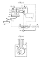
- FIG. 5 is a schematic view of an ink supply-and-discharge system of the image forming apparatus
- FIG. 6 is a schematic view of an example of a tube pump usable as a liquid feed pump and a suction pump of the image forming apparatus;
- FIG. 7 is a schematic block diagram of a controller of the image forming apparatus
- FIG. 8 is a diagram of a drive switching assembly in a first exemplary embodiment of the present disclosure.
- FIG. 9 is a perspective view of the drive switching assembly of FIG. 8 ;
- FIG. 10 is a perspective view of the drive switching assembly from which a cam section is removed for ease of view;
- FIG. 11 is a perspective view of cams and a slider member of the drive switching assembly
- FIG. 12 is a front view of a drive switching assembly in a second exemplary embodiment
- FIG. 13 is a perspective view of a cam of the drive switching assembly of FIG. 12 ;
- FIG. 14 is a schematic view of a drive switching assembly in a third exemplary embodiment
- FIGS. 15A and 15B are schematic views of different states of a drive switching assembly in a fourth exemplary embodiment
- FIGS. 16A and 16B are schematic views of different states of a drive switching assembly in a fifth exemplary embodiment
- FIG. 17 is a chart showing relations between rotation angle of cams and moving amount of switching gears in a drive switching assembly in a sixth exemplary embodiment
- FIGS. 18A and 18B are schematic views of a drive switching assembly in a seventh exemplary embodiment
- FIGS. 19A and 19B are schematic views of a drive switching assembly in an eighth exemplary embodiment
- FIGS. 20A and 20B are schematic views of a drive switching assembly in an ninth exemplary embodiment
- FIGS. 21A to 21C are schematic views of different examples of drive control of a second driving source in a drive switching assembly in a tenth exemplary embodiment
- FIGS. 22A and 22B are flow charts of different examples of drive control of a second driving source in a drive switching assembly in an eleventh exemplary embodiment
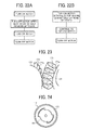
- FIG. 23 is a perspective view of shapes of gears of a drive switching assembly in a twelfth exemplary embodiment.
- FIG. 24 is a perspective view of a driving gear of a drive switching assembly in a thirteenth exemplary embodiment.
- the term "sheet” used herein is not limited to a sheet of paper but includes, e.g., an OHP (overhead projector) sheet, a cloth sheet, a grass sheet, a substrate, or anything on which droplets of ink or other liquid can adhere.
- the term "sheet” is used as a generic term including a recording medium, a recorded medium, a recording sheet, or a recording sheet of paper.
- image forming apparatus refers to an apparatus that ejects ink or any other liquid onto a medium to form images on the medium.
- the medium is made of, for example, paper, string, fiber, cloth, leather, metal, plastic, glass, timber, and ceramic.
- image formation which is used herein as a synonym for “recording” or “printing”, includes providing not only meaningful images, such as characters and figures, but meaningless images, such as patterns, to the medium (in other words, the term “image formation” includes only causing liquid droplets to land on the medium).
- ink is not limited to "ink” in a narrow sense unless specifically distinguished and includes any types of liquid useable for image formation, such as recording liquid, fixing solution, DNA sample, resist, pattern material, and resin.
- image used herein is not limited to a two-dimensional image and includes, for example, an image applied to a three dimensional object and a three dimensional object itself formed as a three-dimensionally molded image.
- image forming apparatus includes e.g., both a serial-type image forming apparatus and a line-type image forming apparatus.
- FIGS. 1 and 2 First, an image forming apparatus according to an exemplary embodiment of this disclosure is described with reference to FIGS. 1 and 2 .
- FIG. 1 is a side view of an entire configuration of the image forming apparatus.
- FIG. 2 is a partial plan view of the image forming apparatus.
- the image forming apparatus is described as a serial-type inkjet recording apparatus. It is to be noted that the image forming apparatus is not limited to such a serial-type inkjet recording apparatus and may be any other type image forming apparatus.
- a carriage 33 is supported on a main guide rod 31 and a sub guide rod 32 so as to be slidable in a direction (main scanning direction) indicated by an arrow MSD in FIG. 2 .
- the main guide rod 31 and the sub guide rod 32 serving as guide members extend between a left-side plate 21A and a right-side plate 21B standing on a main unit 1.
- the carriage 33 is reciprocally moved in the main scanning direction by a main scan motor and a timing belt.
- recording heads 34a and 34b (collectively referred to as “recording heads 34" unless distinguished) serving as liquid ejection heads for ejecting ink droplets of different colors, e.g., yellow (Y), cyan (C), magenta (M), and black (K) .
- the recording heads 34a and 34b are mounted on the carriage 33 so that nozzle rows of multiple nozzles are arranged in a direction (sub-scanning direction) perpendicular to the main scanning direction and ink droplets are ejected downward from the nozzles.
- each of the recording heads 34 has two nozzle rows.
- one of the nozzle rows of the recording head 34a ejects droplets of black (K) ink and the other ejects droplets of cyan (C) ink.
- one of the nozzle rows of the recording head 34b ejects droplets of magenta (M) ink and the other ejects droplets of yellow (Y) ink.
- head tanks 35a and 35b On the carriage 33 are mounted head tanks 35a and 35b (collectively referred to as "head tanks 35" unless distinguished) for supplying the corresponding color inks to the respective nozzle rows.
- a supply pump unit 24 supplies (replenishes) respective color inks from ink cartridges 10Y, 10M, 10C, and 10K to the head tanks 35 via ink supply tubes 36 dedicated for the respective color inks.
- the ink cartridges 10Y, 10M, 10C, and 10K are removably mountable to a cartridge mount portion 4.
- the image forming apparatus further includes a sheet feed section to feed sheets 42 stacked on a sheet stack portion (platen) 41 of a sheet feed tray 2.
- the sheet feed section further includes a sheet feed roller 43 of, e.g., a half moon shape to separate the sheets 42 from the sheet stack portion 41 and feed the sheets 42 sheet by sheet, and a separation pad 44 disposed facing the sheet feed roller 43.
- the separation pad 44 is made of a material of a high friction coefficient and biased (urged) toward the sheet feed roller 43.
- the image forming apparatus To feed the sheet 42 from the sheet feed section to an area below the recording heads 34, the image forming apparatus includes a first guide member 45 to guide the sheet 42, a counter roller 46, a conveyance guide member 47, a regulation member 48 including a front-end guide roller 49, and a conveyance belt 51 to convey the sheet 42 to a position facing the recording head 34 with the sheet 42 electrostatically adhered thereon.
- the conveyance belt 51 is an endless belt that is looped between a conveyance roller 52 and a tension roller 53 so as to circulate in a belt conveyance direction, that is, the sub-scanning direction (SSD).
- a charging roller 56 is provided to charge a surface of the conveyance belt 51.
- the charging roller 56 is disposed so as to contact the surface of the conveyance belt 51 and rotate with the circulation of the conveyance belt 51.
- the conveyance roller 52 is rotated by a sub-scanning motor via a timing roller, the conveyance belt 51 circulates in the sub-scanning direction SSD (belt conveyance direction) illustrated in FIG. 2 .
- the image forming apparatus further includes a sheet output section to output the sheet 42 on which an image has been formed by the recording heads 34.
- the sheet output section includes a separation claw 61 to separate the sheet 42 from the conveyance belt 51, a first output roller 62, a second output roller 63, and a sheet output tray 3 disposed below the first output roller 62.
- a duplex unit 71 is removably mounted on a rear portion of the main unit 1.
- the duplex unit 71 receives the sheet 42.
- the duplex unit 71 turns the sheet 42 upside down to feed the sheet 42 between the counter roller 46 and the conveyance belt 51.
- a manual-feed tray 72 At the top face of the duplex unit 71 is formed a manual-feed tray 72.
- a maintenance unit 81 is disposed at a non-printing area (non-recording area) that is located on one end in the main-scanning direction of the carriage 33.
- the maintenance unit 81 maintains and recovers nozzle conditions of the recording heads 34.
- the maintenance unit 81 includes caps 82a and 82b (hereinafter collectively referred to as "caps 82" unless distinguished) to cover the nozzle faces of the recording heads 34, a wiper member (wiper blade) 83 to wipe the nozzle faces of the recording heads 34, a first droplet receptacle 84 to receive ink droplets ejected by maintenance ejection in which ink droplets are ejected not for image formation but for maintenance, e.g., removal of increased-viscosity ink, and a carriage lock 87 to lock the carriage 33.
- a waste liquid tank 100 is removably mounted to the main unit 1 to store waste ink or liquid generated by the maintenance and recovery operation.
- a second droplet receptacle 88 is disposed at a non-recording area on the opposite end in the main-scanning direction of the carriage 33.
- the second droplet receptacle 88 receives ink droplets ejected by the maintenance ejection during, e.g., recording (image forming) operation.
- the second droplet receptacle 88 has openings 89 arranged in parallel with the nozzle rows of the recording heads 34.
- the sheet 42 is separated sheet by sheet from the sheet feed tray 2, fed in a substantially vertically upward direction, guided along the first guide member 45, and conveyed between the conveyance belt 51 and the counter roller 46. Further, the front tip of the sheet 42 is guided with a conveyance guide 37 and pressed against the conveyance belt 51 by the front-end guide roller 49 to turn the traveling direction of the sheet 42 by approximately 90°.
- plus outputs and minus outputs are alternately applied to the charging roller 56 so that the conveyance belt 51 is charged with an alternating voltage pattern, that is, an alternating band pattern of positively-charged areas and negatively-charged areas in the sub-scanning direction SSD, i.e., the belt circulation direction.
- an alternating voltage pattern that is, an alternating band pattern of positively-charged areas and negatively-charged areas in the sub-scanning direction SSD, i.e., the belt circulation direction.
- ink droplets are ejected onto the sheet 42, which is stopped below the recording heads 34, to form one band of a desired image. Then, the sheet 42 is fed by a certain distance to prepare for the next operation to record another band of the image. Receiving a signal indicating that the image has been recorded or the rear end of the sheet 42 has arrived at the recording area, the recording heads 34 finish the recording operation and the sheet 42 is output to the sheet output tray 3.
- the carriage 33 To perform maintenance-and-recovery operation of the nozzles of the recording heads 34, the carriage 33 is moved to a home position at which the carriage 33 opposes the maintenance unit 81. Then, maintenance-and-recovery operation, such as nozzle suction operation for sucking ink from nozzles with the nozzle faces of the recording heads 34 covered with the caps 82 and/or maintenance ejection for ejecting droplets of ink not contributed to image formation, is performed, thus allowing image formation with stable droplet ejection.
- maintenance-and-recovery operation such as nozzle suction operation for sucking ink from nozzles with the nozzle faces of the recording heads 34 covered with the caps 82 and/or maintenance ejection for ejecting droplets of ink not contributed to image formation, is performed, thus allowing image formation with stable droplet ejection.
- FIG. 3 is a schematic plan view of an example of the head tank 35.
- FIG. 4 is a schematic front view of the head tank 35 illustrated in FIG. 3 .
- the head tank 35 has a tank case 201 forming an ink accommodation part 202 to accommodate ink and having an opening at one side.
- the opening of the tank case 201 is sealed with a flexible film 203, and a spring 204 serving as an elastic member is disposed in the tank case 201 to constantly urge the flexible film 203 outward. Since the outward urging force of the spring 204 constantly acts on the flexible film 203 of the tank case 201, a reduction in the remaining amount of ink in the tank case 201 creates a negative pressure in the tank case 201.
- a detection filler 205 serving as a displacement member is fixed on the flexible film 203 by, e.g., adhesion.
- the detection filler 205 has one end portion pivotably supported on a support shaft 206 and is urged toward the tank case 201.
- the detection filler 205 displaces with the motion of the flexible film 203.
- the displacement amount of the detection filler 205 is detected with a detection sensor 301 that is an optical sensor disposed at the main unit of the image forming apparatus, thus allowing detection of the remaining amount of ink in the head tank 35.
- a supply port portion 209 is disposed at an upper portion of the tank case 201 and connected to the supply tube 36 to deliver ink from the ink cartridge 10 to the ink accommodation part 202.
- an air release unit 207 is disposed at a lateral side of the tank case 201 to release air from the interior of the head tank 35 to the atmosphere.
- the air release unit 207 has an air release passage 207 communicating with the interior of the head tank 35, a valve member 207b to open and close the air release passage 207a, and a spring 207c to urge the valve member 207b into a closed state.
- An air release pin member 302 serving as an air release driving unit is disposed at the main unit 1 of the image forming apparatus, and the valve member 207b is pushed with the air release pin member 302 to open the air release passage 207a, thus causing the interior of the head tank 35 to be open to the atmosphere (in other words, causing the interior of the head tank 35 to communicate with the atmosphere).
- Electrode pins 208a and 208b are mounted to the head tank 35 to detect the remaining amount of ink in the head tank 35. Because of the conductivity of ink, when ink arrives at the electrode pins 208a and 208b, electric current can flow between the electrode pins 208a and 208b, thus causing a change in the resistance values of the electrode pins 208a and 208b. Such a configuration can detect that the liquid level of ink has decreased to a threshold level or lower, i.e., the amount of air in the head tank 35 has increased to a threshold amount or more, or the remaining amount of ink in the head tank 35 has decreased to a threshold amount or lower.
- FIG. 5 an ink supply system connecting the ink cartridge to the head tank is illustrated for only one color for simplicity. However, it is to be noted that the ink supply system is provided for each of the other colors.
- a liquid feed pump 241 serving as a liquid feed unit dedicated for each color is disposed in the supply pump unit 24 to supply ink from the ink cartridge (main tank) 10 to the head tank 35 via the supply tube 36.
- the liquid feed pump 241 is a bidirectional pump, e.g., a tube pump, capable of performing normal feed operation to supply ink from the ink cartridge 10 to the head tank 35 and reverse feed operation to return ink from the head tank 35 to the ink cartridge 10.
- the maintenance unit 81 has the cap 82a to cover the nozzle face of the recording head 34 and a suction pump 812 connected to the cap 82a.
- the suction pump 812 is driven with the nozzle face covered with the cap 82a to suck ink from the nozzles via a suction tube 811, thus allowing ink to be sucked from the head tank 35.
- the ink sucked from the head tank 35 is discharged as waste ink to the waste liquid tank 100.
- the air release pin member 302 serving as an air release driving unit (pressing member) is disposed to open and close the air release unit 207. By moving the air release pin member 302, the air release unit 207 can be opened.
- the detection sensor 301 serving as an optical sensor is disposed at the main unit 1 of the image forming apparatus to detect the detection filler 205.
- the driving force of a first driving motor 101 (M1 in FIG. 5 ) serving as a first driving source is selectively transmitted to the liquid feed pumps 241 dedicated for the respective colors, the suction pump 812, and the air release pin member 302 via a drive switching assembly 400.
- the drive switching assembly 400 is driven with a second driving motor 102 (M2 in FIG. 5 ) serving as a second driving source (switching drive source).
- Driving of the first driving motor 101 is controlled with the controller 500.
- a tube pump 901 can transfer liquid through a tube 902 while compressing the tube 902 by an eccentric pressing roller 903 bidirectionally rotatable as indicated by an arrow R in FIG. 6 .
- rotating the pressing roller 903 in respective directions indicated by the arrow R allows ink to be fed from the ink cartridge 10 to the head tank 35 and in reverse from the head tank 35 to the ink cartridge 10.
- rotating the pressing roller 903 in one direction allows ink to be sucked from the nozzles.
- FIG. 7 is a block diagram of a controller 500 of the image forming apparatus.
- the controller 500 includes a central processing unit (CPU) 501, a read-only memory (ROM) 502, a random access memory (RAM) 503, a non-volatile memory 504, and an application-specific integrated circuit (ASIC) 505.
- the CPU 501 manages the control of the entire image forming apparatus.
- the ROM 502 stores programs executed by the CPU 501 or other fixed data, and the RAM 503 temporarily stores image and other data.
- the non-volatile memory 504 is a rewritable memory capable of retaining data even when the apparatus is powered off.
- the ASIC 505 processes various signals on image data, performs sorting or other image processing, and processes input and output signals to control the entire apparatus.
- the controller 500 also includes a print control unit 508, a head driver (driver integrated circuit) 509, a main scanning motor 554, a sub-scanning motor 555, a first motor driving unit 510, an alternating current (AC) bias supply unit 511, and a second motor driving unit 512.
- the print control unit 508 includes a data transfer section and a driving signal generating section to drive and control the recording heads 34.
- the head driver 509 is disposed at the carriage 33 to drive the recording heads 34.
- the main scanning motor 554 moves the carriage 33 for scanning, and the sub-scanning motor 555 circulates the conveyance roller 51.
- the first motor driving unit 510 drives the main scanning motor 554 and the sub-scanning motor 555.
- the AC bias supply unit 511 supplies an AC bias to the charging roller 56.
- the second motor driving unit 512 drives the first driving motor 101 and the second driving motor 102 of the drive switching mechanism 600.
- the controller 500 is connected to an operation panel 514 for inputting and displaying information necessary to the image forming apparatus.
- the controller 500 includes a host interface (I/F) 506 for transmitting and receiving data and signals to and from a host 600, such as an information processing device (e.g., personal computer), image reading device (e.g., image scanner), or imaging device (e.g., digital camera), via a cable or network.
- a host 600 such as an information processing device (e.g., personal computer), image reading device (e.g., image scanner), or imaging device (e.g., digital camera), via a cable or network.
- an information processing device e.g., personal computer
- image reading device e.g., image scanner
- imaging device e.g., digital camera
- the CPU 501 of the controller 500 reads and analyzes print data stored in a reception buffer of the host I/F 506, performs desired image processing, data sorting, or other processing with the ASIC 505, and transfers image data to the head driver 509. It is to be noted that dot-pattern data for image output may be created by a printer driver 601 of the host 600.
- the print control unit 508 transfers the above-described image data as serial data, and outputs to the head driver 509, for example, transfer clock signals, latch signals, and control signals required for the transfer of image data and determination of the transfer.
- the print control unit 508 has a driving signal generating section including, e.g., a digital/analog (D/A) converter (to perform digital/analog conversion on pattern data of driving pulses stored on the ROM 502), a voltage amplifier, and a current amplifier, and outputs a driving signal containing one or more driving pulses to the head driver 509.
- D/A digital/analog
- the head driver 509 selects driving pulses forming driving signals transmitted from the print control unit 508 and applies the selected driving pulses to driving elements (e.g., piezoelectric elements) to drive the recording heads 34.
- driving elements e.g., piezoelectric elements
- the driving elements serve as pressure generators to generate energy for ejecting liquid droplets from the recording heads 34.
- the recording heads 34 can selectively eject different sizes of droplets, e.g., large droplets, middle droplets, and small droplets to form different sizes of dots on a recording medium.
- An input/output (I/O) unit 513 obtains information from a group of sensors 515 mounted in the image forming apparatus, extracts information required for controlling printing operation, and controls the print control unit 508, the first motor driving unit 510, and the AC bias supply unit 511 based on the extracted information.
- the group of sensors 515 includes, for example, an optical sensor to detect the position of the sheet of recording media, a thermistor to monitor temperature and/or humidity in the apparatus, a voltage sensor to monitor the voltage of a charging belt, and an interlock switch to detect the opening and closing of a cover.
- the I/O unit 513 processes information from such various types of sensors.
- the controller 500 also has a timer 520 to measure time.
- FIG. 8 is a schematic view of a drive switching assembly 400 in the first exemplary embodiment.
- FIG. 9 is a perspective view of the drive switching assembly 400.
- FIG. 10 is a perspective view of the drive switching assembly 400 from which a cam section is removed for ease of view.
- FIG. 11 is a perspective view of cams and a slider member.
- broken lines P indicate a relationship in which two gears constantly engage with each other
- chain double-dashed lines Q indicate a relationship in which two gears detachably engage with each other. The same goes for the following drawings.
- gears 104A and 104B are mounted on a driving shaft 104 rotated by the first driving motor 101.
- Cams 103A and 103B (hereinafter, referred to as “cams 103" unless distinguished) are mounted on a cam shaft 131 rotated by the second driving motor 102 of the drive switching assembly 400.
- Each of the cams 103A and 103B has a cam groove 107.
- the drive switching assembly 400 also has slider members 105A to 105D (hereinafter, referred to as "slider members 105" unless distinguished).
- Slider members 105" Each of the slider members 105A to 105D has an engagement portion 105a to engage the cam groove 107 of the cam 103A or 103B and is moved along a thrust direction indicated by each of arrows D1 to D4 in FIG. 8 with rotation of the cam 103A or 103B.
- the engagement portions 105a of the slider members 105 are detached from the cam grooves 107 of the cams 103 for ease of view. However, actually, as described above, the engagement portions 105a of the slider members 105 slidably contact the cam grooves 107 of the cams 103.
- a switching gear 106A that engages the gear 104A rotated by the first driving motor 101.
- a switching gear 106B that engages the gear 104B rotated by the first driving motor 101.
- a switching gear 106C that engages the gear 104A rotated by the first driving motor 101.
- a switching gear 106D that engages the gear 104B rotated by the first driving motor 101.
- Movement of the slider member 105A causes the switching gear 106A to move between an engagement position to engage either a driving gear 112a of a liquid feed pump 241 for, e.g., a first color or a driving gear 112b of a liquid feed pump 241 for, e.g., a second color and a disengagement (separate) position to disengage (separate) from any of the driving gears 112a and 112b.
- Movement of the slider member 105B causes the switching gear 106B to move between an engagement position to engage either a driving gear 112c of a liquid feed pump 241 for, e.g., a third color or a driving gear 112d of a liquid feed pump 241 for, e.g., a fourth color and a disengagement (separate) position to disengage (separate) from any of the driving gears 112c and 112d.
- Movement of the slider member 105C causes the switching gear 106C to move between an engagement position to engage a driving gear 113 of the suction pump 812 of the maintenance unit 81 and a disengagement (separate) position to disengage (separate) from the driving gear 113.
- Movement of the slider member 105D causes the switching gear 106D to move between an engagement position to engage a driving gear 114 for reciprocally moving the air release pin member 302 and a disengagement (separate) position to disengage (separate) from the driving gear 114.
- each of the switching gears 106A and 106B serves as a first switching gear
- the switching gear 106C serves as a second switching gear
- the switching gear 106D serves as a third switching gear.
- the first to fourth colors of inks supplied from the four liquid feed pumps 241 are, e.g., black, cyan, magenta, and yellow.
- the driving force of the first driving motor 101 is transmitted to the driving shaft 104 via a motor gear 141, a gear 142 rotatably mounted on a support shaft 152, and a gear 143 fixed on the driving shaft 104.
- the driving force of the second driving motor 102 serving as a switching drive source is transmitted to the cam shaft 131 via a motor gear 132, a gear 133, and a gear 134 fixed on the cam shaft 131.
- the slider member 105A, the switching gear 106A, the slider member 105B, and the switching gear 106B are supported on a support shaft 151.
- the slider member 105C, the switching gear 106C, the switching gear 105D, and the slider member 106D are supported on a support shaft 152.
- driving the first driving motor 101 causes the driving force to be transmitted to the first switching gears 106A and 106B, the second switching gear 106C, and the third switching gear 106D via the gears 104A and 104B, thus rotating the switching gears 106A to 106D.
- the driving force of the first driving motor 101 is transmitted to the liquid feed pumps 241, thus allowing the liquid feed pumps 241 to be driven in any of the normal feed direction (normal rotation direction) and the reverse feed direction (reverse rotation direction).
- the configuration of the drive switching assembly is not limited to the above-described configuration.
- the switching gears 106A to 106D may be switched in turn with rotation of the cams 103A and 103B or, by contrast, may be simultaneously coupled with a plurality of driving gears.
- Using a plurality of cams can reduce the distance at which one cam moves the switching gear, thus resulting in a reduced diameter of the cam. Additionally, using the plurality of cams allows, for example, five or more switching gears to be arranged in the thrust direction (axial direction) without changing dimensions in directions other than the thrust direction.
- the image forming apparatus includes a first driving source to drive a plurality of liquid feed pumps and a drive switching assembly to selectively transmit the driving force of the first driving source to the plurality of liquid feed pumps.
- the drive switching assembly has a second driving source, cams rotated by the second driving source, slider members moved along the thrust direction with rotation of the cams, and first switching gears that receives the driving force of the first driving source and is moved between engagement positions to engage driving gears of the plurality of liquid feed pumps and a disengagement position to disengage from any of the driving gears.
- the driving force of the first driving source is selectively transmitted to the plurality of liquid feed pumps. Since the driving source of the pumps is separated from the driving force of the drive switching assembly, such a configuration allows the plurality of pumps to be driven by a small number of driving sources with a relatively high degree of freedom.
- use of the drive switching assembly according to this exemplary embodiment allows the normal and reverse rotation of the first driving source to be transmitted independent of the driving gears of other pumps and units.
- use of the drive switching assembly allows relatively free operation without constraints from other pumps and units.
- FIG. 12 is a front view of the drive switching assembly.
- FIG. 13 is a perspective view of a cam of the drive switching assembly.
- four slider members 105 and four switching gears 106 are supported on a support shaft 161 so as to be movable in predetermined ranges.
- Springs 109 are disposed between the slider members 105 and support plates 162 to urge the slider members 105.
- cams 108 are fixed on a cam shaft 131 rotated by a second driving source and arranged in the axial direction of the cam shaft 131.
- the cam 108 has a recessed portion 108a into which an engagement portion 105a of the slider member 105 can fit.
- the switching gear 106 moves in the thrust direction along with the slider member 105 and engages a driving gear 111 of a corresponding liquid feed pump 241.
- Such a configuration allows the switching gears 106 to in turn engage and separate from the driving gears 111 of the plurality of liquid feed pumps with rotation of the cams 108, thus allowing selective transmission of the driving force to the plurality of liquid feed pumps.
- the slider member 105 is pressed against the side face of the cam 108 with the spring 109.
- the spring 109 contracts to prevent the second driving source for rotating the cam 108 from losing synchronization due to inadequate engagement of the switching gear 106 with the driving gear 111.
- FIG. 14 is a schematic view of the drive switching assembly.
- a slider member 105 is moved with a single cam 103 along a thrust direction to move a switching gear 106 in thrust direction.
- the switching gear 106 selectively engages three driving gears 112a to 112c to transmit the driving force of the first driving motor 101 to any one of the driving gear 112a to 112c.
- Such a configuration allows transmission of the driving force to be switched with a single switching gear without using two opposed switching gears as described in the above-described exemplary embodiments.
- the gradient of a cam groove 107 in the cam 103 is preferably small to move the slider member 105 smoothly, resulting in an increased diameter of the cam 103.
- FIGS. 15A and 15B a drive switching assembly in a fourth exemplary embodiment of the present disclosure is described with reference to FIGS. 15A and 15B .
- FIGS. 15A and 15B are schematic views of different states of the drive switching assembly in the fourth exemplary embodiment.
- cams themselves are movable on cam shafts.
- a moving cam 116 is movable in the axial direction of a cam shaft 131 rotated by a second driving motor and rotatable with the cam shaft 131 in a rotation direction of the cam shaft 131.
- the moving cam 116 is cylindrical, and has a cam groove 107 at an inner side and cam faces 117 at both ends in the axial direction of the cam shaft.
- the cam groove 107 has a cam curve along the outer circumference of the moving cam 116, and each cam face 117 has a cam curve along the outer circumference.
- holder rib 115 are fixed so as to slidably contact the cam faces 117 of the moving cam 116, thus positioning the moving cam 116 with respect to a thrust direction indicated by an arrow D5 in FIGS. 15A and 15B .
- a slider member 105 moves in a thrust direction indicated by an arrow D6 in FIGS. 15A and 15B with an engagement portion 105a thereof engaging the cam groove 107 of the moving cam 116.
- the moving cam 116 moves in the thrust direction D5 along the cam faces 117 of both edges of the moving cam 116.
- the drive switching assembly shifts from, e.g., a state illustrated in FIG. 15A to a state illustrated in FIG. 15B .
- the slider member 105 relatively moves by a total of a moving amount of the slider member 105 along the cam groove 107 and a moving amount of the moving cam 116 along the cam faces 117.
- Such a configuration can increase the moving amount of the slider member by the amount in which the moving cam 116 moves along the cam faces 117, as compared with a drive switching assembly having cam grooves of the same diameter and the same gradient as described in the first exemplary embodiment.
- the slider member 105 can move smoothly and obtain a relatively large moving amount of the slider member with a relatively small cam size.
- FIGS. 16A and 16B a drive switching assembly in a fifth exemplary embodiment of the present disclosure is described with reference to FIGS. 16A and 16B .
- FIGS. 16A and 16B are schematic views of different states of the drive switching assembly in the fifth exemplary embodiment.
- cams themselves are movable on cam shafts like the fourth exemplary embodiment.
- a moving cam 118 is movable in the axial direction of a cam shaft 131 rotated by a second driving motor and rotatable with the cam shaft 131 in a rotation direction of the cam shaft 131.
- the moving cam 118 has a cam groove 107 at an inner side and ribs 121 at both ends in the axial direction of the cam shaft.
- the cam groove 107 has a cam curve along the outer circumference of the moving cam 118, and the ribs 121 slidably contact the respective cam faces 120 of the fixed cams 119.
- a slider member 105 moves in a thrust direction (indicated by an arrow D7 in FIGS. 16A and 16B ) with an engagement portion 105a thereof engaging the cam groove 107 of the moving cam 118.
- the ribs 121 of both edges of the moving cam 118 move along the cam faces 120 of the fixed cams 119, thus moving the moving cam 118 in a thrust direction indicated by an arrow D8 in FIGS. 16A and 16B .
- the drive switching assembly shifts from, e.g., a state illustrated in FIG. 16A to a state illustrated in FIG. 16B .
- the slider member 105 relatively moves by a total of a moving amount of the slider member 105 along the cam groove 107 and a moving amount of the moving cam 118 along the cam faces 120.
- Such a configuration can obtain effects equivalent to those of the above-described fourth exemplary embodiment.
- FIG. 17 is a chart showing relations between the rotation angle of cams and the moving amount of switching gears in the drive switching assembly.
- the configuration of the above-described first exemplary embodiment is modified so that, by changing the phases of the switching gears 106A to 106D, the switching gears 106A to 106D are in turn connected once to the driving gears 112a to 112d, the driving gear 113, and the driving gear 114 during every rotation of the cams 103A and 103B.
- Such a configuration allows the driving gears 112a to 112d to drive independently of one another.
- the driving gear 113 of the maintenance unit moves to an area away from the switching gear 106D to turn into a free state.
- the driving gear 114 of the air release pin member 302 moves to an area away from the switching gear 106C to turn into a free state.
- switching operation for rotating the cams 103 and transmission operation for transmitting the driving force are performed independent of each other, not simultaneously.
- Such a configuration can prevent misoperation even if two switching gears are temporarily connected to driving gears at the same time, thus reducing the gradient of each cam line graph.
- a movement angle of 60 degrees is allocated to each of the switching gears 106A to 106D.
- the movement angle of each switching gear is set to be 120 degrees.
- FIGS. 18A and 18B a drive switching assembly in a seventh exemplary embodiment of the present disclosure is described with reference to FIGS. 18A and 18B .
- FIGS. 18A and 18B are schematic views of the drive switching assembly.
- switching gears are urged with springs. More specifically, in a drive switching assembly like that of the first exemplary embodiment that moves switching gears with cam grooves to switch driving gears, the switching gears are urged with springs.
- the switching gear 106 is mounted on a shaft 122 of a slider member 105 so as to be slidable in the axial direction of the shaft 122.
- a spring 124a is disposed between a support portion 123a at one end of the shaft 122 of the slider member 105 and one end face of the switching gear 106 in the axial direction
- a spring 124b is disposed between a support portion 123b at the opposite end of the shaft 122 of the slider member 105 and the opposite end face of the switching gear 106 in the axial direction.
- the urging force of the spring works only when the switching gear 106 strikes the driving gear 112.
- the load to the second driving source can be reduced.
- FIGS. 19A and 19B a drive switching assembly in an eighth exemplary embodiment of the present disclosure is described with reference to FIGS. 19A and 19B .
- FIGS. 19A and 19B are schematic views of the drive switching assembly.
- the drive switching assembly according to the above-described seventh exemplary embodiment is modified so that the lengths of springs 124a and 124b in the extending direction are restricted with stoppers 125a and 125b.
- the stoppers 125a and 125b hold front ends of the springs 124a and 124b, respectively, (at the side proximal to a switching gear 106) and are movable relative to support portions 123a and 123b, and the maximum movable ranges of the stoppers 125a and 125b are restricted with rear-end ribs 126.
- the position of the switching gear 106 may shift in the axial direction due to a difference in urging force between the springs 124a and 124b at both sides of the switching gear 106.
- the stoppers 125a and 125b are disposed to position the switching gear 106 by dimension, thus increasing the positional accuracy.
- the spring forces of the springs 124a and 124b do not constantly act on the switching gear 106, thus obtaining a reduced rotation torque of the switching gear 106.
- FIGS. 20A and 20B a drive switching assembly in a ninth exemplary embodiment of the present disclosure is described with reference to FIGS. 20A and 20B .
- FIGS. 20A and 20B are schematic views of the drive switching assembly.
- the drive switching assembly according to the above-described eighth exemplary embodiment is modified so that stoppers 125a and 125b are held with a switching gear 106.
- the stoppers 125a and 125b hold rear ends of springs 124a and 124b proximal to support portions 123a and 123b, respectively, and the switching gear 106 holds front ends of the springs 124a and 124b distal to the support portions 123a and 123b, respectively.
- the stoppers 125a and 125b are movable relative to the switching gear 106, and the maximum movable ranges of the stoppers 125a and 125b are restricted by contacting rear-end ribs 126 of the stoppers 125a and 125b with the switching gear 106.
- FIGS. 21A, 21B, and 21C a drive switching assembly in a tenth exemplary embodiment of the present disclosure is described with reference to FIGS. 21A, 21B, and 21C .
- FIGS. 21A to 21C are schematic views of different examples of drive control of a second driving source in the drive switching assembly.
- the teeth of a switching gear might conflict with and not engage the teeth of a driving gear smoothly.
- the teeth of the switching gear remains unengaged with the teeth of the driving gear until the first driving source is activated.
- the urging force of a spring causes the teeth of the switching gear to engage the teeth of the driving gear.
- the urging force of the spring is so weak that, e.g., a time during which the teeth of the switching gear moves by one tooth at an engagement position becomes shorter than a time during which the switching gear is urged with the spring to engage the driving gear, the teeth of the switching gear might be rejected by the teeth of the driving gear, thus hampering smooth engagement of the switching gear with the driving gear.
- the acceleration of the second driving source is set to be low in a first region T1 and high in a second region T2.
- the second driving source is rotated at a low speed range in a first region T1 and at a constant speed in a second region T2.
- the second driving source is accelerated at the same acceleration as that in the first region T 1 to reach a target speed.
- the first example is combined with the second example.
- the second driving source is driven at a low speed range in a first region T1 and at a constant speed in a second region T2.
- the second driving source is accelerated at an acceleration higher than that in the first region T1 to reach a target speed.
- the speed of the second driving motor is maintained at such a speed that the teeth of the switching gear can engage the teeth of the driving gear. Then, the speed of the second driving motor is increased to a target speed.
- Such drive control allows more reliable engagement of the switching gear with the driving gear.
- FIGS. 22A and 22B are flow charts of different examples of drive control of a second driving source in the drive switching assembly.
- the switching gear 106 conflict with the driving gear 112
- the switching gear 106 by moving the switching gear 106 at half of a tooth and stopping it, the switching gear 106 securely engages the driving gear 112 or other gear by the urging force of the spring.
- the drive control for desired operation is performed, thus reliably engaging the switching gear with the driving gear.
- the second driving motor 102 is turned on with a pulse for moving the switching gear 106 by half or more of a tooth. The turning-on state is maintained until a desired moving amount of the switching gear 106 is obtained. When the desired moving amount is obtained, the second driving motor 102 is turned off.
- the driving of the switching gear 106 is controlled with zero or several teeth plus half of a tooth to reliably shift the phase of teeth, thus more securely engaging the switching gear 106 with the driving gear 112.
- FIG. 23 is a perspective view of shapes of gears of the drive switching assembly in the twelfth exemplary embodiment.
- Teeth 171 of a switching gear 106 and teeth 172 of a driving gear 112 have slant faces 171a and 172b at opposed side faces in the thrust direction.
- the side faces of the teeth 171 and 172 are chamfered and further processed to have sharp edges.
- the switching gear 106 engages the driving gear 112 from the thrust direction, the teeth 171 is less likely to conflict with the teeth 172.
- the switching gear 106 smoothly engages the driving gear 112, thus preventing loss of synchronization of the second driving source.
- the shapes of the side faces of the teeth 171 and 172 may be only chamfered or processed to have sharp edges.
- gear shape of the driving gear 112 is described.
- gear shapes can be applied to the shapes of other driving gears.
- FIG. 24 is a perspective view of a driving gear of the drive switching assembly in the thirteenth exemplary embodiment.
- a driving gear 112 connectable to a switching gear 106 has a shaft portion 181 and a gear portion 182.
- the gear portion 182 is mounted on the shaft portion 181 so as to have a play of plus or minus half or more of a tooth relative to the shaft portion 181.
- the play between the shaft portion 181 and the gear portion 182 allows rotation of the driving gear 112.
- the switching gear 106 engages the driving gear 112 without striking the driving gear 112, thus preventing loss of synchronization of the second driving source due to an increased load resulting from striking of the switching gear 106 against the driving gear 112 from the thrust direction.
- one of the other gears may have a gear portion and a shaft portion as described above. Even if the one of the other gears does not directly engage the switching gear, such a configuration can obtain effects equivalent to those of the above-described configuration that the driving gear 112 has the shaft portion 181 and the gear portion 182 with the play.
Landscapes
- Ink Jet (AREA)
Abstract
Description
- This disclosure relates to an image forming apparatus, and more specifically to an image forming apparatus including a recording head for ejecting liquid droplets.
- Image forming apparatuses are used as printers, facsimile machines, copiers, plotters, or multi-functional devices having two or more of the foregoing capabilities. As one type of image forming apparatus employing a liquid-ejection recording method, an inkjet recording apparatus is known that uses a recording head (liquid-droplet ejection head) for ejecting droplets of ink.
- Such an image forming apparatus may have, for example, replaceable main tanks (ink cartridges) and head tanks. The main tanks store different color inks to be supplied to one or more recording heads for ejecting ink droplets of different colors. The head tanks dedicated for the respective color inks receive the color inks from the main tanks and supply the inks to the recording heads.
- Such an image forming apparatus may also have a maintenance unit to maintain and recover the performance of the recording heads. The maintenance unit typically has suction caps to cover the nozzle faces of the recording heads and a suction pump connected to the suction caps to suck ink from nozzles of the recording heads.
- Furthermore, such an image forming apparatus may have an air release unit and an air release driving unit. The air release unit is disposed at the head tank and openable to release air from the interior of the head tank to the atmosphere. The air release driving unit is disposed at a main unit of the apparatus to drive the air release unit.
- In a case where such an image forming apparatus has multiple pumps, such as liquid feed pumps and the suction pump, if multiple driving motors are provided as dedicated driving sources for driving the respective pumps, the image forming apparatus increases in size and cost.
- Hence, for example,
JP2003-145802-A - However, the above-described configuration poses difficulty in activating the pumps independent of one another, as compared to a configuration in which dedicated driving sources for the respective pumps are employed. In addition, since the driving (rotation) direction of the pumps is limited to one direction, the above-described configuration has difficulty in applying to, e.g., a case where liquid feed pumps for feeding liquid in both directions are used.
- In light of the above-described problems, one purpose of the present invention is to provide an image forming apparatus capable of driving pumps and/or other units with a relatively high degree of freedom by using a relatively small number of driving sources.
- In one aspect, the invention resides in an image forming apparatus including a recording head, a plurality of head tanks, a plurality of replaceable main tanks, a plurality of liquid feed pumps, a first driving source, and a drive switching assembly. The recording head ejects droplets of liquids. The plurality of head tanks supplies the liquids to the recording head. The plurality of replaceable main tanks stores the liquids to be supplied to the recording head. The plurality of liquid feed pumps feeds the liquids from the plurality of main tanks to the plurality of head tanks and in reverse from the plurality of head tanks to the plurality of main tanks. The first driving source drives the plurality of liquid feed pumps. The drive switching assembly selectively transmits a driving force of the first driving source to the plurality of liquid feed pumps. The drive switching assembly includes a second driving source, a cam, a slider member, and a switching gear. The cam is rotated by the second driving source. The slider member is movable in a thrust direction with rotation of the cam. The switching gear receives the driving force of the first driving source and is movable with the slider member between positions to engage driving gears of the plurality of liquid feed pumps and a position to disengage from the driving gears of the plurality of liquid feed pumps. With movement of the switching gear, the driving force of the first driving source is selectively transmitted to the plurality of liquid feed pumps.
- The aforementioned and other aspects, features, and advantages of the present disclosure would be better understood by reference to the following detailed description when considered in connection with the accompanying drawings, wherein:
-
FIG. 1 is a schematic side view of a mechanical section of an image forming apparatus according to an exemplary embodiment of the present disclosure; -
FIG. 2 is a plan view of the mechanical section of the image forming apparatus illustrated inFIG. 1 ; -
FIG. 3 is a schematic plan view of an example of a head tank of the image forming apparatus; -
FIG. 4 is a schematic front view of the head tank illustrated inFIG. 3 ; -
FIG. 5 is a schematic view of an ink supply-and-discharge system of the image forming apparatus; -
FIG. 6 is a schematic view of an example of a tube pump usable as a liquid feed pump and a suction pump of the image forming apparatus; -
FIG. 7 is a schematic block diagram of a controller of the image forming apparatus; -
FIG. 8 is a diagram of a drive switching assembly in a first exemplary embodiment of the present disclosure; -
FIG. 9 is a perspective view of the drive switching assembly ofFIG. 8 ; -
FIG. 10 is a perspective view of the drive switching assembly from which a cam section is removed for ease of view; -
FIG. 11 is a perspective view of cams and a slider member of the drive switching assembly; -
FIG. 12 is a front view of a drive switching assembly in a second exemplary embodiment; -
FIG. 13 is a perspective view of a cam of the drive switching assembly ofFIG. 12 ; -
FIG. 14 is a schematic view of a drive switching assembly in a third exemplary embodiment; -
FIGS. 15A and 15B are schematic views of different states of a drive switching assembly in a fourth exemplary embodiment; -
FIGS. 16A and 16B are schematic views of different states of a drive switching assembly in a fifth exemplary embodiment -
FIG. 17 is a chart showing relations between rotation angle of cams and moving amount of switching gears in a drive switching assembly in a sixth exemplary embodiment; -
FIGS. 18A and 18B are schematic views of a drive switching assembly in a seventh exemplary embodiment; -
FIGS. 19A and 19B are schematic views of a drive switching assembly in an eighth exemplary embodiment; -
FIGS. 20A and 20B are schematic views of a drive switching assembly in an ninth exemplary embodiment; -
FIGS. 21A to 21C are schematic views of different examples of drive control of a second driving source in a drive switching assembly in a tenth exemplary embodiment; -
FIGS. 22A and 22B are flow charts of different examples of drive control of a second driving source in a drive switching assembly in an eleventh exemplary embodiment; -
FIG. 23 is a perspective view of shapes of gears of a drive switching assembly in a twelfth exemplary embodiment; and -
FIG. 24 is a perspective view of a driving gear of a drive switching assembly in a thirteenth exemplary embodiment. - The accompanying drawings are intended to depict exemplary embodiments of the present disclosure and should not be interpreted to limit the scope thereof. The accompanying drawings are not to be considered as drawn to scale unless explicitly noted.
- In describing embodiments illustrated in the drawings, specific terminology is employed for the sake of clarity. However, the disclosure of this patent specification is not intended to be limited to the specific terminology so selected and it is to be understood that each specific element includes all technical equivalents that operate in a similar manner and achieve similar results.
- In this disclosure, the term "sheet" used herein is not limited to a sheet of paper but includes, e.g., an OHP (overhead projector) sheet, a cloth sheet, a grass sheet, a substrate, or anything on which droplets of ink or other liquid can adhere. In other words, the term "sheet" is used as a generic term including a recording medium, a recorded medium, a recording sheet, or a recording sheet of paper. The term "image forming apparatus" refers to an apparatus that ejects ink or any other liquid onto a medium to form images on the medium. The medium is made of, for example, paper, string, fiber, cloth, leather, metal, plastic, glass, timber, and ceramic. The term "image formation", which is used herein as a synonym for "recording" or "printing", includes providing not only meaningful images, such as characters and figures, but meaningless images, such as patterns, to the medium (in other words, the term "image formation" includes only causing liquid droplets to land on the medium).
- The term "ink" as used herein is not limited to "ink" in a narrow sense unless specifically distinguished and includes any types of liquid useable for image formation, such as recording liquid, fixing solution, DNA sample, resist, pattern material, and resin. The term "image" used herein is not limited to a two-dimensional image and includes, for example, an image applied to a three dimensional object and a three dimensional object itself formed as a three-dimensionally molded image. The term "image forming apparatus" includes e.g., both a serial-type image forming apparatus and a line-type image forming apparatus.
- Although the exemplary embodiments are described with technical limitations with reference to the attached drawings, such description is not intended to limit the scope of the invention and all of the components or elements described in the exemplary embodiments of this disclosure are not necessarily indispensable to the present invention.
- Referring now to the drawings, wherein like reference numerals designate identical or corresponding parts throughout the several views, exemplary embodiments of the present disclosure are described below.
- First, an image forming apparatus according to an exemplary embodiment of this disclosure is described with reference to
FIGS. 1 and2 . -
FIG. 1 is a side view of an entire configuration of the image forming apparatus.FIG. 2 is a partial plan view of the image forming apparatus. In this exemplary embodiment, the image forming apparatus is described as a serial-type inkjet recording apparatus. It is to be noted that the image forming apparatus is not limited to such a serial-type inkjet recording apparatus and may be any other type image forming apparatus. - In the image forming apparatus, a
carriage 33 is supported on amain guide rod 31 and asub guide rod 32 so as to be slidable in a direction (main scanning direction) indicated by an arrow MSD inFIG. 2 . Themain guide rod 31 and thesub guide rod 32 serving as guide members extend between a left-side plate 21A and a right-side plate 21B standing on amain unit 1. Thecarriage 33 is reciprocally moved in the main scanning direction by a main scan motor and a timing belt. - On the
carriage 33 are mounted recording heads 34a and 34b (collectively referred to as "recording heads 34" unless distinguished) serving as liquid ejection heads for ejecting ink droplets of different colors, e.g., yellow (Y), cyan (C), magenta (M), and black (K) . The recording heads 34a and 34b are mounted on thecarriage 33 so that nozzle rows of multiple nozzles are arranged in a direction (sub-scanning direction) perpendicular to the main scanning direction and ink droplets are ejected downward from the nozzles. - For example, each of the recording heads 34 has two nozzle rows. In such a case, for example, one of the nozzle rows of the
recording head 34a ejects droplets of black (K) ink and the other ejects droplets of cyan (C) ink. In addition, one of the nozzle rows of therecording head 34b ejects droplets of magenta (M) ink and the other ejects droplets of yellow (Y) ink. - On the
carriage 33 are mountedhead tanks head tanks 35" unless distinguished) for supplying the corresponding color inks to the respective nozzle rows. Asupply pump unit 24 supplies (replenishes) respective color inks fromink cartridges head tanks 35 viaink supply tubes 36 dedicated for the respective color inks. Theink cartridges cartridge mount portion 4. - The image forming apparatus further includes a sheet feed section to feed
sheets 42 stacked on a sheet stack portion (platen) 41 of asheet feed tray 2. The sheet feed section further includes asheet feed roller 43 of, e.g., a half moon shape to separate thesheets 42 from thesheet stack portion 41 and feed thesheets 42 sheet by sheet, and aseparation pad 44 disposed facing thesheet feed roller 43. Theseparation pad 44 is made of a material of a high friction coefficient and biased (urged) toward thesheet feed roller 43. - To feed the
sheet 42 from the sheet feed section to an area below the recording heads 34, the image forming apparatus includes afirst guide member 45 to guide thesheet 42, acounter roller 46, aconveyance guide member 47, aregulation member 48 including a front-end guide roller 49, and aconveyance belt 51 to convey thesheet 42 to a position facing therecording head 34 with thesheet 42 electrostatically adhered thereon. - The
conveyance belt 51 is an endless belt that is looped between aconveyance roller 52 and atension roller 53 so as to circulate in a belt conveyance direction, that is, the sub-scanning direction (SSD). A chargingroller 56 is provided to charge a surface of theconveyance belt 51. The chargingroller 56 is disposed so as to contact the surface of theconveyance belt 51 and rotate with the circulation of theconveyance belt 51. When theconveyance roller 52 is rotated by a sub-scanning motor via a timing roller, theconveyance belt 51 circulates in the sub-scanning direction SSD (belt conveyance direction) illustrated inFIG. 2 . - The image forming apparatus further includes a sheet output section to output the
sheet 42 on which an image has been formed by the recording heads 34. The sheet output section includes aseparation claw 61 to separate thesheet 42 from theconveyance belt 51, afirst output roller 62, asecond output roller 63, and asheet output tray 3 disposed below thefirst output roller 62. - A
duplex unit 71 is removably mounted on a rear portion of themain unit 1. When theconveyance belt 51 rotates in reverse to return thesheet 42, theduplex unit 71 receives thesheet 42. Then theduplex unit 71 turns thesheet 42 upside down to feed thesheet 42 between thecounter roller 46 and theconveyance belt 51. At the top face of theduplex unit 71 is formed a manual-feed tray 72. - As illustrated in
FIG. 2 , amaintenance unit 81 is disposed at a non-printing area (non-recording area) that is located on one end in the main-scanning direction of thecarriage 33. Themaintenance unit 81 maintains and recovers nozzle conditions of the recording heads 34. Themaintenance unit 81 includescaps carriage lock 87 to lock thecarriage 33. Below themaintenance unit 81, awaste liquid tank 100 is removably mounted to themain unit 1 to store waste ink or liquid generated by the maintenance and recovery operation. - A
second droplet receptacle 88 is disposed at a non-recording area on the opposite end in the main-scanning direction of thecarriage 33. Thesecond droplet receptacle 88 receives ink droplets ejected by the maintenance ejection during, e.g., recording (image forming) operation. Thesecond droplet receptacle 88 hasopenings 89 arranged in parallel with the nozzle rows of the recording heads 34. - In the image forming apparatus having the above-described configuration, the
sheet 42 is separated sheet by sheet from thesheet feed tray 2, fed in a substantially vertically upward direction, guided along thefirst guide member 45, and conveyed between theconveyance belt 51 and thecounter roller 46. Further, the front tip of thesheet 42 is guided with a conveyance guide 37 and pressed against theconveyance belt 51 by the front-end guide roller 49 to turn the traveling direction of thesheet 42 by approximately 90°. - At this time, plus outputs and minus outputs, i.e., positive and negative supply voltages are alternately applied to the charging
roller 56 so that theconveyance belt 51 is charged with an alternating voltage pattern, that is, an alternating band pattern of positively-charged areas and negatively-charged areas in the sub-scanning direction SSD, i.e., the belt circulation direction. When thesheet 42 is fed onto theconveyance belt 51 alternately charged with positive and negative charges, thesheet 42 is adhered to theconveyance belt 51 and conveyed in the sub scanning direction by circulation of theconveyance belt 51. - By driving the recording heads 34 in response to image signals while moving the
carriage 33, ink droplets are ejected onto thesheet 42, which is stopped below the recording heads 34, to form one band of a desired image. Then, thesheet 42 is fed by a certain distance to prepare for the next operation to record another band of the image. Receiving a signal indicating that the image has been recorded or the rear end of thesheet 42 has arrived at the recording area, the recording heads 34 finish the recording operation and thesheet 42 is output to thesheet output tray 3. - To perform maintenance-and-recovery operation of the nozzles of the recording heads 34, the
carriage 33 is moved to a home position at which thecarriage 33 opposes themaintenance unit 81. Then, maintenance-and-recovery operation, such as nozzle suction operation for sucking ink from nozzles with the nozzle faces of the recording heads 34 covered with the caps 82 and/or maintenance ejection for ejecting droplets of ink not contributed to image formation, is performed, thus allowing image formation with stable droplet ejection. - Next, an example of the head tank is described with reference to
FIGS. 3 and 4 . -
FIG. 3 is a schematic plan view of an example of thehead tank 35.FIG. 4 is a schematic front view of thehead tank 35 illustrated inFIG. 3 . - The
head tank 35 has atank case 201 forming anink accommodation part 202 to accommodate ink and having an opening at one side. The opening of thetank case 201 is sealed with aflexible film 203, and aspring 204 serving as an elastic member is disposed in thetank case 201 to constantly urge theflexible film 203 outward. Since the outward urging force of thespring 204 constantly acts on theflexible film 203 of thetank case 201, a reduction in the remaining amount of ink in thetank case 201 creates a negative pressure in thetank case 201. - At the exterior of the
tank case 201, adetection filler 205 serving as a displacement member is fixed on theflexible film 203 by, e.g., adhesion. Thedetection filler 205 has one end portion pivotably supported on asupport shaft 206 and is urged toward thetank case 201. - As a result, the
detection filler 205 displaces with the motion of theflexible film 203. The displacement amount of thedetection filler 205 is detected with adetection sensor 301 that is an optical sensor disposed at the main unit of the image forming apparatus, thus allowing detection of the remaining amount of ink in thehead tank 35. - A
supply port portion 209 is disposed at an upper portion of thetank case 201 and connected to thesupply tube 36 to deliver ink from theink cartridge 10 to theink accommodation part 202. At a lateral side of thetank case 201 is disposed anair release unit 207 to release air from the interior of thehead tank 35 to the atmosphere. - The
air release unit 207 has anair release passage 207 communicating with the interior of thehead tank 35, avalve member 207b to open and close theair release passage 207a, and aspring 207c to urge thevalve member 207b into a closed state. An airrelease pin member 302 serving as an air release driving unit is disposed at themain unit 1 of the image forming apparatus, and thevalve member 207b is pushed with the airrelease pin member 302 to open theair release passage 207a, thus causing the interior of thehead tank 35 to be open to the atmosphere (in other words, causing the interior of thehead tank 35 to communicate with the atmosphere). -
Electrode pins head tank 35 to detect the remaining amount of ink in thehead tank 35. Because of the conductivity of ink, when ink arrives at theelectrode pins electrode pins electrode pins head tank 35 has increased to a threshold amount or more, or the remaining amount of ink in thehead tank 35 has decreased to a threshold amount or lower. - Next, an ink supply-and-discharge system of the image forming apparatus is described with reference to
FIG. 5 . - In
FIG. 5 , an ink supply system connecting the ink cartridge to the head tank is illustrated for only one color for simplicity. However, it is to be noted that the ink supply system is provided for each of the other colors. - A
liquid feed pump 241 serving as a liquid feed unit dedicated for each color is disposed in thesupply pump unit 24 to supply ink from the ink cartridge (main tank) 10 to thehead tank 35 via thesupply tube 36. Theliquid feed pump 241 is a bidirectional pump, e.g., a tube pump, capable of performing normal feed operation to supply ink from theink cartridge 10 to thehead tank 35 and reverse feed operation to return ink from thehead tank 35 to theink cartridge 10. - The
maintenance unit 81, as described above, has thecap 82a to cover the nozzle face of therecording head 34 and asuction pump 812 connected to thecap 82a. Thesuction pump 812 is driven with the nozzle face covered with thecap 82a to suck ink from the nozzles via asuction tube 811, thus allowing ink to be sucked from thehead tank 35. The ink sucked from thehead tank 35 is discharged as waste ink to thewaste liquid tank 100. - At the
main unit 1 of the image forming apparatus, the airrelease pin member 302 serving as an air release driving unit (pressing member) is disposed to open and close theair release unit 207. By moving the airrelease pin member 302, theair release unit 207 can be opened. Thedetection sensor 301 serving as an optical sensor is disposed at themain unit 1 of the image forming apparatus to detect thedetection filler 205. - The driving force of a first driving motor 101 (M1 in
FIG. 5 ) serving as a first driving source is selectively transmitted to the liquid feed pumps 241 dedicated for the respective colors, thesuction pump 812, and the airrelease pin member 302 via adrive switching assembly 400. Thedrive switching assembly 400 is driven with a second driving motor 102 (M2 inFIG. 5 ) serving as a second driving source (switching drive source). Driving of thefirst driving motor 101 is controlled with thecontroller 500. - Next, an example of a tube pump used as the
liquid feed pump 241 and thesuction pump 812 is described with reference toFIG. 6 . - A
tube pump 901 can transfer liquid through atube 902 while compressing thetube 902 by an eccentricpressing roller 903 bidirectionally rotatable as indicated by an arrow R inFIG. 6 . - In a case where the
tube pump 901 is used as theliquid feed pump 241, rotating thepressing roller 903 in respective directions indicated by the arrow R allows ink to be fed from theink cartridge 10 to thehead tank 35 and in reverse from thehead tank 35 to theink cartridge 10. In a case where thetube pump 901 is used as thesuction pump 812, rotating thepressing roller 903 in one direction allows ink to be sucked from the nozzles. - Next, an example of the controller of the image forming apparatus is described with reference to
FIG. 7 . -
FIG. 7 is a block diagram of acontroller 500 of the image forming apparatus. Thecontroller 500 includes a central processing unit (CPU) 501, a read-only memory (ROM) 502, a random access memory (RAM) 503, anon-volatile memory 504, and an application-specific integrated circuit (ASIC) 505. TheCPU 501 manages the control of the entire image forming apparatus. TheROM 502 stores programs executed by theCPU 501 or other fixed data, and theRAM 503 temporarily stores image and other data. Thenon-volatile memory 504 is a rewritable memory capable of retaining data even when the apparatus is powered off. TheASIC 505 processes various signals on image data, performs sorting or other image processing, and processes input and output signals to control the entire apparatus. - The
controller 500 also includes aprint control unit 508, a head driver (driver integrated circuit) 509, amain scanning motor 554, asub-scanning motor 555, a firstmotor driving unit 510, an alternating current (AC) biassupply unit 511, and a secondmotor driving unit 512. Theprint control unit 508 includes a data transfer section and a driving signal generating section to drive and control the recording heads 34. Thehead driver 509 is disposed at thecarriage 33 to drive the recording heads 34. Themain scanning motor 554 moves thecarriage 33 for scanning, and thesub-scanning motor 555 circulates theconveyance roller 51. The firstmotor driving unit 510 drives themain scanning motor 554 and thesub-scanning motor 555. The ACbias supply unit 511 supplies an AC bias to the chargingroller 56. The secondmotor driving unit 512 drives thefirst driving motor 101 and thesecond driving motor 102 of thedrive switching mechanism 600. - The
controller 500 is connected to anoperation panel 514 for inputting and displaying information necessary to the image forming apparatus. - The
controller 500 includes a host interface (I/F) 506 for transmitting and receiving data and signals to and from ahost 600, such as an information processing device (e.g., personal computer), image reading device (e.g., image scanner), or imaging device (e.g., digital camera), via a cable or network. - The
CPU 501 of thecontroller 500 reads and analyzes print data stored in a reception buffer of the host I/F 506, performs desired image processing, data sorting, or other processing with theASIC 505, and transfers image data to thehead driver 509. It is to be noted that dot-pattern data for image output may be created by aprinter driver 601 of thehost 600. - The
print control unit 508 transfers the above-described image data as serial data, and outputs to thehead driver 509, for example, transfer clock signals, latch signals, and control signals required for the transfer of image data and determination of the transfer. In addition, theprint control unit 508 has a driving signal generating section including, e.g., a digital/analog (D/A) converter (to perform digital/analog conversion on pattern data of driving pulses stored on the ROM 502), a voltage amplifier, and a current amplifier, and outputs a driving signal containing one or more driving pulses to thehead driver 509. - In accordance with serially-inputted image data corresponding to one image line recorded by the recording heads 34, the
head driver 509 selects driving pulses forming driving signals transmitted from theprint control unit 508 and applies the selected driving pulses to driving elements (e.g., piezoelectric elements) to drive the recording heads 34. At this time, the driving elements serve as pressure generators to generate energy for ejecting liquid droplets from the recording heads 34. By selecting a part or all of the driving pulses forming the driving signals, the recording heads 34 can selectively eject different sizes of droplets, e.g., large droplets, middle droplets, and small droplets to form different sizes of dots on a recording medium. - An input/output (I/O)
unit 513 obtains information from a group ofsensors 515 mounted in the image forming apparatus, extracts information required for controlling printing operation, and controls theprint control unit 508, the firstmotor driving unit 510, and the ACbias supply unit 511 based on the extracted information. The group ofsensors 515 includes, for example, an optical sensor to detect the position of the sheet of recording media, a thermistor to monitor temperature and/or humidity in the apparatus, a voltage sensor to monitor the voltage of a charging belt, and an interlock switch to detect the opening and closing of a cover. The I/O unit 513 processes information from such various types of sensors. Additionally, information of the above-describedelectrode pins detection sensor 301 to detect thedetection filler 205 of thehead tank 35 are input to the I/O unit 513. Thecontroller 500 also has atimer 520 to measure time. - Next, a drive switching assembly in a first exemplary embodiment of the present disclosure is described with reference to
FIGS. 8 to 11 . -
FIG. 8 is a schematic view of adrive switching assembly 400 in the first exemplary embodiment.FIG. 9 is a perspective view of thedrive switching assembly 400.FIG. 10 is a perspective view of thedrive switching assembly 400 from which a cam section is removed for ease of view.FIG. 11 is a perspective view of cams and a slider member. - In
FIG. 8 , broken lines P indicate a relationship in which two gears constantly engage with each other, and chain double-dashed lines Q indicate a relationship in which two gears detachably engage with each other. The same goes for the following drawings. - In the
drive switching assembly 400, gears 104A and 104B are mounted on a drivingshaft 104 rotated by thefirst driving motor 101. - Cams 103A and 103B (hereinafter, referred to as "
cams 103" unless distinguished) are mounted on acam shaft 131 rotated by thesecond driving motor 102 of thedrive switching assembly 400. Each of thecams cam groove 107. - The
drive switching assembly 400 also hasslider members 105A to 105D (hereinafter, referred to as "slider members 105" unless distinguished). Each of theslider members 105A to 105D has anengagement portion 105a to engage thecam groove 107 of thecam FIG. 8 with rotation of thecam - In
FIG. 8 , theengagement portions 105a of theslider members 105 are detached from thecam grooves 107 of thecams 103 for ease of view. However, actually, as described above, theengagement portions 105a of theslider members 105 slidably contact thecam grooves 107 of thecams 103. - On the
slider member 105A is rotatably mounted aswitching gear 106A that engages thegear 104A rotated by thefirst driving motor 101. On theslider member 105B is rotatably mounted aswitching gear 106B that engages thegear 104B rotated by thefirst driving motor 101. - On the
slider member 105C is rotatably mounted aswitching gear 106C that engages thegear 104A rotated by thefirst driving motor 101. On theslider member 105D is rotatably mounted aswitching gear 106D that engages thegear 104B rotated by thefirst driving motor 101. - Movement of the
slider member 105A causes theswitching gear 106A to move between an engagement position to engage either adriving gear 112a of aliquid feed pump 241 for, e.g., a first color or adriving gear 112b of aliquid feed pump 241 for, e.g., a second color and a disengagement (separate) position to disengage (separate) from any of the driving gears 112a and 112b. - Movement of the
slider member 105B causes theswitching gear 106B to move between an engagement position to engage either adriving gear 112c of aliquid feed pump 241 for, e.g., a third color or adriving gear 112d of aliquid feed pump 241 for, e.g., a fourth color and a disengagement (separate) position to disengage (separate) from any of the driving gears 112c and 112d. - Movement of the
slider member 105C causes theswitching gear 106C to move between an engagement position to engage adriving gear 113 of thesuction pump 812 of themaintenance unit 81 and a disengagement (separate) position to disengage (separate) from thedriving gear 113. - Movement of the
slider member 105D causes theswitching gear 106D to move between an engagement position to engage adriving gear 114 for reciprocally moving the airrelease pin member 302 and a disengagement (separate) position to disengage (separate) from thedriving gear 114. - In this exemplary embodiment, each of the switching gears 106A and 106B serves as a first switching gear, the
switching gear 106C serves as a second switching gear, and theswitching gear 106D serves as a third switching gear. The first to fourth colors of inks supplied from the four liquid feed pumps 241 are, e.g., black, cyan, magenta, and yellow. - In the configuration illustrated in
FIGS. 9 to 11 , the driving force of thefirst driving motor 101 is transmitted to the drivingshaft 104 via amotor gear 141, agear 142 rotatably mounted on asupport shaft 152, and agear 143 fixed on the drivingshaft 104. The driving force of thesecond driving motor 102 serving as a switching drive source is transmitted to thecam shaft 131 via amotor gear 132, agear 133, and agear 134 fixed on thecam shaft 131. Theslider member 105A, theswitching gear 106A, theslider member 105B, and theswitching gear 106B are supported on asupport shaft 151. Theslider member 105C, theswitching gear 106C, theswitching gear 105D, and theslider member 106D are supported on asupport shaft 152. - For such a configuration, driving the
first driving motor 101 causes the driving force to be transmitted to the first switching gears 106A and 106B, thesecond switching gear 106C, and thethird switching gear 106D via thegears - When the
cams second driving motor 102, theslider members 105A to 105D move along the respective directions indicated by the arrows D1 to D4 inFIG. 8 , and the first switching gears 106A and 106B, thesecond switching gear 106C, and thethird switching gear 106D also move along the respective directions indicated by the arrows D1 to D4 inFIG. 8 . - When the
first switching gear 106A moves to the position to engage thedriving gear 112a, theliquid feed pump 241 for the first color is driven. Likewise, when thefirst switching gear 106A moves to the position to engage thedriving gear 106B, theliquid feed pump 241 for the second color is driven. - When the
slider member 105B moves along the direction indicated by the arrow D2 and thefirst switching gear 106B moves to the position to engage thedriving gear 112c, theliquid feed pump 241 for the third color is driven. Likewise, when thefirst switching gear 106B moves to the position to engage thedriving gear 112d, theliquid feed pump 241 for the fourth color is driven. - When the
slider member 105C moves along the direction indicated by the arrow D3 and thesecond switching gear 106C moves to the position to engage thedriving gear 113, thesuction pump 812 of themaintenance unit 81 is driven. - When the
slider member 105D moves along the direction indicated by the arrow D4 and thethird switching gear 106D moves to the position to engage thedriving gear 114, the airrelease pin member 302 is driven for reciprocal movement. - For such a configuration, as the
first driving motor 101 rotates in any of clockwise and counterclockwise directions, the driving force of thefirst driving motor 101 is transmitted to the liquid feed pumps 241, thus allowing the liquid feed pumps 241 to be driven in any of the normal feed direction (normal rotation direction) and the reverse feed direction (reverse rotation direction). - It is to be noted that the configuration of the drive switching assembly is not limited to the above-described configuration. For example, by adjusting the phases of the
cam grooves 107 of thecams slider members 105 to thecams cams - Using a plurality of cams (in this example, two cams) can reduce the distance at which one cam moves the switching gear, thus resulting in a reduced diameter of the cam. Additionally, using the plurality of cams allows, for example, five or more switching gears to be arranged in the thrust direction (axial direction) without changing dimensions in directions other than the thrust direction.
- As described above, the image forming apparatus according to this exemplary embodiment includes a first driving source to drive a plurality of liquid feed pumps and a drive switching assembly to selectively transmit the driving force of the first driving source to the plurality of liquid feed pumps. The drive switching assembly has a second driving source, cams rotated by the second driving source, slider members moved along the thrust direction with rotation of the cams, and first switching gears that receives the driving force of the first driving source and is moved between engagement positions to engage driving gears of the plurality of liquid feed pumps and a disengagement position to disengage from any of the driving gears. By moving the first switching gears, the driving force of the first driving source is selectively transmitted to the plurality of liquid feed pumps. Since the driving source of the pumps is separated from the driving force of the drive switching assembly, such a configuration allows the plurality of pumps to be driven by a small number of driving sources with a relatively high degree of freedom.
- In other words, use of the drive switching assembly according to this exemplary embodiment allows the normal and reverse rotation of the first driving source to be transmitted independent of the driving gears of other pumps and units. Thus, as with a configuration in which a single driving source is used, use of the drive switching assembly allows relatively free operation without constraints from other pumps and units.
- Next, a drive switching assembly in a second exemplary embodiment of the present disclosure is described with reference to
FIGS. 12 and 13 . -
FIG. 12 is a front view of the drive switching assembly.FIG. 13 is a perspective view of a cam of the drive switching assembly. - In this exemplary embodiment, four
slider members 105 and four switchinggears 106 are supported on asupport shaft 161 so as to be movable in predetermined ranges.Springs 109 are disposed between theslider members 105 andsupport plates 162 to urge theslider members 105. - Four
cams 108 are fixed on acam shaft 131 rotated by a second driving source and arranged in the axial direction of thecam shaft 131. Thecam 108 has a recessedportion 108a into which anengagement portion 105a of theslider member 105 can fit. - For such a configuration, when the
cam shaft 131 is rotated by the second driving source with theengagement portion 105a of theslider member 105 contacting a side face of thecam 108, thecam 108 rotates and theengagement portion 105a of theslider member 105 fits into the recessedportion 108a of thecam 108. As a result, theslider member 105 is moved in a thrust direction (axial direction of the support shaft 161) by urging force of thespring 109. - When the
engagement portion 105a of theslider member 105 fits into the recessedportion 108a of the cam 108 (e.g., the state of the leftmost one of theslider members 105 inFIG. 12 ), theswitching gear 106 moves in the thrust direction along with theslider member 105 and engages adriving gear 111 of a correspondingliquid feed pump 241. - By contrast, in a case where the
engagement portion 105a of theslider member 105 has already fitted in the recessedportion 108a of thecam 108, theengagement portion 105a separates from the recessedportion 108a with rotation of thecam 108. As a result, theswitching gear 106 moves in the thrust direction along with theslider member 105 and separates from thedriving gear 111 of the correspondingliquid feed pump 241. - Such a configuration allows the switching gears 106 to in turn engage and separate from the driving gears 111 of the plurality of liquid feed pumps with rotation of the
cams 108, thus allowing selective transmission of the driving force to the plurality of liquid feed pumps. - For such a configuration, the
slider member 105 is pressed against the side face of thecam 108 with thespring 109. As a result, even if teeth of theswitching gear 106 do not engage teeth of thedriving gear 111 well in connecting theswitching gear 106 to thedriving gear 111, thespring 109 contracts to prevent the second driving source for rotating thecam 108 from losing synchronization due to inadequate engagement of theswitching gear 106 with thedriving gear 111. - Next, a drive switching assembly in a third exemplary embodiment of the present disclosure is described with reference to
FIG. 14 . -
FIG. 14 is a schematic view of the drive switching assembly. In this exemplary embodiment, aslider member 105 is moved with asingle cam 103 along a thrust direction to move aswitching gear 106 in thrust direction. As a result, theswitching gear 106 selectively engages three drivinggears 112a to 112c to transmit the driving force of thefirst driving motor 101 to any one of thedriving gear 112a to 112c. - Such a configuration allows transmission of the driving force to be switched with a single switching gear without using two opposed switching gears as described in the above-described exemplary embodiments. In this case, however, the gradient of a
cam groove 107 in thecam 103 is preferably small to move theslider member 105 smoothly, resulting in an increased diameter of thecam 103. - Next, a drive switching assembly in a fourth exemplary embodiment of the present disclosure is described with reference to
FIGS. 15A and 15B . -
FIGS. 15A and 15B are schematic views of different states of the drive switching assembly in the fourth exemplary embodiment. In this exemplary embodiment, cams themselves are movable on cam shafts. In other words, as illustrated inFIGS. 15A and 15B , a movingcam 116 is movable in the axial direction of acam shaft 131 rotated by a second driving motor and rotatable with thecam shaft 131 in a rotation direction of thecam shaft 131. - The moving
cam 116 is cylindrical, and has acam groove 107 at an inner side and cam faces 117 at both ends in the axial direction of the cam shaft. Thecam groove 107 has a cam curve along the outer circumference of the movingcam 116, and eachcam face 117 has a cam curve along the outer circumference. - Outside both edges of the moving
cam 116 in the axial direction,holder rib 115 are fixed so as to slidably contact the cam faces 117 of the movingcam 116, thus positioning the movingcam 116 with respect to a thrust direction indicated by an arrow D5 inFIGS. 15A and 15B . - For such a configuration, as the
cam shaft 131 is rotated by a second driving motor to rotate the movingcam 116, aslider member 105 moves in a thrust direction indicated by an arrow D6 inFIGS. 15A and 15B with anengagement portion 105a thereof engaging thecam groove 107 of the movingcam 116. Simultaneously, the movingcam 116 moves in the thrust direction D5 along the cam faces 117 of both edges of the movingcam 116. - As the moving
cam 116 rotates, the drive switching assembly shifts from, e.g., a state illustrated inFIG. 15A to a state illustrated inFIG. 15B . Theslider member 105 relatively moves by a total of a moving amount of theslider member 105 along thecam groove 107 and a moving amount of the movingcam 116 along the cam faces 117. - Such a configuration can increase the moving amount of the slider member by the amount in which the moving
cam 116 moves along the cam faces 117, as compared with a drive switching assembly having cam grooves of the same diameter and the same gradient as described in the first exemplary embodiment. In this configuration, since the gradient of thecam groove 107 is invariant, theslider member 105 can move smoothly and obtain a relatively large moving amount of the slider member with a relatively small cam size. - Next, a drive switching assembly in a fifth exemplary embodiment of the present disclosure is described with reference to
FIGS. 16A and 16B . -
FIGS. 16A and 16B are schematic views of different states of the drive switching assembly in the fifth exemplary embodiment. In this exemplary embodiment, cams themselves are movable on cam shafts like the fourth exemplary embodiment. In other words, as illustrated inFIGS. 16A and 16B , a movingcam 118 is movable in the axial direction of acam shaft 131 rotated by a second driving motor and rotatable with thecam shaft 131 in a rotation direction of thecam shaft 131. - Outside both edges of the moving
cam 118 in the axial direction, fixedcams 119 having cam faces 120 opposing both edge faces of the movingcam 118 are disposed. The movingcam 118 has acam groove 107 at an inner side andribs 121 at both ends in the axial direction of the cam shaft. Thecam groove 107 has a cam curve along the outer circumference of the movingcam 118, and theribs 121 slidably contact the respective cam faces 120 of the fixedcams 119. - For such a configuration, as a
cam actuator shaft 131 is rotated by a second driving motor to rotate the movingcam 118, aslider member 105 moves in a thrust direction (indicated by an arrow D7 inFIGS. 16A and 16B ) with anengagement portion 105a thereof engaging thecam groove 107 of the movingcam 118. Simultaneously, theribs 121 of both edges of the movingcam 118 move along the cam faces 120 of the fixedcams 119, thus moving the movingcam 118 in a thrust direction indicated by an arrow D8 inFIGS. 16A and 16B . - As the moving
cam 118 rotates, the drive switching assembly shifts from, e.g., a state illustrated inFIG. 16A to a state illustrated inFIG. 16B . Theslider member 105 relatively moves by a total of a moving amount of theslider member 105 along thecam groove 107 and a moving amount of the movingcam 118 along the cam faces 120. Such a configuration can obtain effects equivalent to those of the above-described fourth exemplary embodiment. - Next, a drive switching assembly in a sixth exemplary embodiment of the present disclosure is described with reference to
FIG. 17 . -
FIG. 17 is a chart showing relations between the rotation angle of cams and the moving amount of switching gears in the drive switching assembly. - In this exemplary embodiment, the configuration of the above-described first exemplary embodiment is modified so that, by changing the phases of the switching gears 106A to 106D, the switching gears 106A to 106D are in turn connected once to the driving
gears 112a to 112d, thedriving gear 113, and thedriving gear 114 during every rotation of thecams gears 112a to 112d to drive independently of one another. - As shown in
FIG. 17 , in a region A in which thedriving gear 112a of the liquid feed pump 241 (pump 1 inFIG. 17 ) is connected to theswitching gear 106A, thedriving gear 113 of the maintenance unit moves to an area away from theswitching gear 106D to turn into a free state. In a region B in which thedriving gear 112d of the liquid feed pump 241 (pump 4 inFIG. 17 ) is connected to theswitching gear 106B, thedriving gear 114 of the airrelease pin member 302 moves to an area away from theswitching gear 106C to turn into a free state. - In a region C, even if the switching gears 106A and 106C are connected to the
driving gear first driving motor 101 is stopped. Thus, the gradient of cam line graphs (the cam grooves 107) of thecams - In other words, switching operation for rotating the
cams 103 and transmission operation for transmitting the driving force are performed independent of each other, not simultaneously. Such a configuration can prevent misoperation even if two switching gears are temporarily connected to driving gears at the same time, thus reducing the gradient of each cam line graph. - Since 360 degrees of full rotation are divided by six driving gears, typically, a movement angle of 60 degrees is allocated to each of the switching gears 106A to 106D. However, as described above, since the first driving source is not driven during movement of the switching gears 106A to 106D, two switching gears may temporarily be connected to driving gears at the same time. Therefore, in
FIG. 17 , the movement angle of each switching gear is set to be 120 degrees. - Next, a drive switching assembly in a seventh exemplary embodiment of the present disclosure is described with reference to
FIGS. 18A and 18B . -
FIGS. 18A and 18B are schematic views of the drive switching assembly. In this exemplary embodiment, switching gears are urged with springs. More specifically, in a drive switching assembly like that of the first exemplary embodiment that moves switching gears with cam grooves to switch driving gears, the switching gears are urged with springs. - In other words, the
switching gear 106 is mounted on ashaft 122 of aslider member 105 so as to be slidable in the axial direction of theshaft 122. Aspring 124a is disposed between asupport portion 123a at one end of theshaft 122 of theslider member 105 and one end face of theswitching gear 106 in the axial direction, and aspring 124b is disposed between asupport portion 123b at the opposite end of theshaft 122 of theslider member 105 and the opposite end face of theswitching gear 106 in the axial direction. - For such a configuration, even if teeth of the
switching gear 106 conflict with and do not engage teeth of thedriving gear 112 when theslider member 105 moves, e.g., from a state illustrated inFIG. 18A to a state illustrated inFIG. 18B , thespring 124b contracts to absorb the conflict. Such a configuration prevents excess load on a second driving motor (second driving source) that rotates thecam 103 to move theswitching gear 106, thus allowing the driving gears to be switched without loss of synchronization of the second driving motor. - In addition, for such a configuration, the urging force of the spring works only when the
switching gear 106 strikes thedriving gear 112. Thus, as compared to a case where theswitching gear 106 is constantly urged with a spring(s), the load to the second driving source can be reduced. - Next, a drive switching assembly in an eighth exemplary embodiment of the present disclosure is described with reference to
FIGS. 19A and 19B . -
FIGS. 19A and 19B are schematic views of the drive switching assembly. In this exemplary embodiment, the drive switching assembly according to the above-described seventh exemplary embodiment is modified so that the lengths ofsprings stoppers stoppers springs portions stoppers end ribs 126. - In other words, for the configuration of the above-described seventh exemplary embodiment, the position of the
switching gear 106 may shift in the axial direction due to a difference in urging force between thesprings switching gear 106. Hence, in this exemplary embodiment, thestoppers switching gear 106 by dimension, thus increasing the positional accuracy. In this configuration, the spring forces of thesprings switching gear 106, thus obtaining a reduced rotation torque of theswitching gear 106. - Next, a drive switching assembly in a ninth exemplary embodiment of the present disclosure is described with reference to
FIGS. 20A and 20B . -
FIGS. 20A and 20B are schematic views of the drive switching assembly. In this exemplary embodiment, the drive switching assembly according to the above-described eighth exemplary embodiment is modified so thatstoppers switching gear 106. Thestoppers springs portions switching gear 106 holds front ends of thesprings support portions stoppers switching gear 106, and the maximum movable ranges of thestoppers end ribs 126 of thestoppers switching gear 106. - Next, a drive switching assembly in a tenth exemplary embodiment of the present disclosure is described with reference to
FIGS. 21A, 21B, and 21C . -
FIGS. 21A to 21C are schematic views of different examples of drive control of a second driving source in the drive switching assembly. In the above-described exemplary embodiments, since switching gears move in the thrust direction to switch driving gears for transmitting the drive force, the teeth of a switching gear might conflict with and not engage the teeth of a driving gear smoothly. - In such a case, as described above, for the exemplary embodiments in which springs (elastic members) are used, the teeth of the switching gear remains unengaged with the teeth of the driving gear until the first driving source is activated. When the first driving source is activated, the urging force of a spring causes the teeth of the switching gear to engage the teeth of the driving gear. However, even in such a configuration, if the urging force of the spring is so weak that, e.g., a time during which the teeth of the switching gear moves by one tooth at an engagement position becomes shorter than a time during which the switching gear is urged with the spring to engage the driving gear, the teeth of the switching gear might be rejected by the teeth of the driving gear, thus hampering smooth engagement of the switching gear with the driving gear.
- Hence, for this exemplary embodiment, in a first example illustrated in
FIG. 21A , the acceleration of the second driving source is set to be low in a first region T1 and high in a second region T2. - In a second example illustrated in
FIG. 21B , the second driving source is rotated at a low speed range in a first region T1 and at a constant speed in a second region T2. In a third region T3, the second driving source is accelerated at the same acceleration as that in thefirst region T 1 to reach a target speed. - In a third example illustrated in
FIG. 21C , the first example is combined with the second example. In other words, the second driving source is driven at a low speed range in a first region T1 and at a constant speed in a second region T2. In a third region T3, the second driving source is accelerated at an acceleration higher than that in the first region T1 to reach a target speed. In other words, at least while the teeth of the switching gear moves by half of one tooth, the speed of the second driving motor is maintained at such a speed that the teeth of the switching gear can engage the teeth of the driving gear. Then, the speed of the second driving motor is increased to a target speed. Such drive control allows more reliable engagement of the switching gear with the driving gear. - Next, a drive switching assembly in an eleventh exemplary embodiment of the present disclosure is described with reference to
FIGS. 22A and 22B . -
FIGS. 22A and 22B are flow charts of different examples of drive control of a second driving source in the drive switching assembly. - In a first example illustrated in
FIG. 22A , when aswitching gear 106 moves by half of a tooth after the turning on of asecond driving motor 102, thesecond driving motor 102 is temporarily turned off Then, thesecond driving motor 102 is turned on, and after theswitching gear 106 moves by a desired amount, thesecond driving motor 102 is turned off. - In the above-described exemplary embodiments in which springs are used, if the
switching gear 106 conflict with thedriving gear 112, by moving theswitching gear 106 at half of a tooth and stopping it, theswitching gear 106 securely engages thedriving gear 112 or other gear by the urging force of the spring. Thus, after theswitching gear 106 is rotated at half of a tooth and temporarily stopped, the drive control for desired operation is performed, thus reliably engaging the switching gear with the driving gear. - In a second example illustrated in
FIG. 22B , thesecond driving motor 102 is turned on with a pulse for moving theswitching gear 106 by half or more of a tooth. The turning-on state is maintained until a desired moving amount of theswitching gear 106 is obtained. When the desired moving amount is obtained, thesecond driving motor 102 is turned off. For the drive control for rotating theswitching gear 106 by half or more of a tooth, the driving of theswitching gear 106 is controlled with zero or several teeth plus half of a tooth to reliably shift the phase of teeth, thus more securely engaging theswitching gear 106 with thedriving gear 112. - Next, a drive switching assembly in a twelfth exemplary embodiment of the present disclosure is described with reference to
FIG. 23 . -
FIG. 23 is a perspective view of shapes of gears of the drive switching assembly in the twelfth exemplary embodiment.Teeth 171 of aswitching gear 106 andteeth 172 of adriving gear 112 have slant faces 171a and 172b at opposed side faces in the thrust direction. In other words, the side faces of theteeth - As a result, when the
switching gear 106 engages thedriving gear 112 from the thrust direction, theteeth 171 is less likely to conflict with theteeth 172. Thus, theswitching gear 106 smoothly engages thedriving gear 112, thus preventing loss of synchronization of the second driving source. Alternatively, the shapes of the side faces of theteeth - In this exemplary embodiment, the gear shape of the
driving gear 112 is described. Likewise, the above-described gear shapes can be applied to the shapes of other driving gears. - Next, a drive switching assembly in a thirteenth exemplary embodiment of the present disclosure is described with reference to
FIG. 24 . -
FIG. 24 is a perspective view of a driving gear of the drive switching assembly in the thirteenth exemplary embodiment. Adriving gear 112 connectable to aswitching gear 106 has ashaft portion 181 and agear portion 182. Thegear portion 182 is mounted on theshaft portion 181 so as to have a play of plus or minus half or more of a tooth relative to theshaft portion 181. - For such a configuration, even if the teeth of the
switching gear 106 conflicts with the teeth of thedriving gear 112 when theswitching gear 106 engages thedriving gear 112 from the thrust direction, the play between theshaft portion 181 and thegear portion 182 allows rotation of thedriving gear 112. As a result, theswitching gear 106 engages thedriving gear 112 without striking thedriving gear 112, thus preventing loss of synchronization of the second driving source due to an increased load resulting from striking of theswitching gear 106 against thedriving gear 112 from the thrust direction. - Alternatively, in a case where other gears are connected to a downstream side of the driving gear, one of the other gears may have a gear portion and a shaft portion as described above. Even if the one of the other gears does not directly engage the switching gear, such a configuration can obtain effects equivalent to those of the above-described configuration that the
driving gear 112 has theshaft portion 181 and thegear portion 182 with the play.
Claims (10)
- An image forming apparatus comprising:a recording head (34) to eject droplets of liquids;a plurality of head tanks (35) to supply the liquids to the recording head (34);a plurality of replaceable main tanks (10) to store the liquids to be supplied to the recording head (34);a plurality of liquid feed pumps (241) to feed the liquids from the plurality of main tanks (10) to the plurality of head tanks (35) and in reverse from the plurality of head tanks (35) to the plurality of main tanks (10);a first driving source (101) to drive the plurality of liquid feed pumps (241); anda drive switching assembly (400) to selectively transmit a driving force of the first driving source (101) to the plurality of liquid feed pumps (241),the drive switching assembly (400) including
a second driving source (102),
a cam (107) rotated by the second driving source (102),
a slider member (105) movable in a thrust direction with rotation of the cam (107), and
a switching gear (106) to receive the driving force of the first driving source (101) and movable with the slider member (105) between positions to engage driving gears (112) of the plurality of liquid feed pumps (241) and a position to disengage from the driving gears (112) of the plurality of liquid feed pumps (241),
wherein, with movement of the switching gear (106), the driving force of the first driving source (101) is selectively transmitted to the plurality of liquid feed pumps (241). - The image forming apparatus of claim 1, further comprising a maintenance unit (81) to maintain and recover the recording head (34),
the maintenance unit (81) comprising:a cap member (82) to cover a nozzle face of the recording head (34); anda suction pump (812) connected to the cap member (82),wherein the drive switching assembly (400) includes a second switching gear (106C) to receive the driving force of the first driving source (101) and movable with the slider member (105) between a position to engage a driving gear (113) of the maintenance unit (81) and a position to disengage from the driving gear (113) of the maintenance unit (81). - The image forming apparatus of claim 1 or 2, wherein each of the plurality of head tanks (35) has an air release unit (207) openable to release air from an interior of the each of the plurality of head tanks (35) to atmosphere,
the image forming apparatus further comprises an air release driving unit (302) at a main unit of the image forming apparatus to drive the air release unit (207), and
the drive switching assembly (400) includes a third switching gear (106D) to receive the driving force of the first driving source (101) and movable with the slider member (105) between a position to engage a driving gear (114) of the air release unit (207) and a position to disengage from the driving gear (114) of the air release unit (207). - The image forming apparatus of any of claims 1 to 3, wherein the switching gear (106) selectively engages a plurality of driving gears (112) coaxially arranged.
- The image forming apparatus of any of claims 1 to 4, wherein the cam (107) and the slider member (105) are provided in a ratio of one to two or more.
- The image forming apparatus of any of claims 1 to 5, wherein the drive switching assembly (400) further includes an elastic member (124) to urge the switching gear (106) in a direction in which the switching gear (106) moves.
- The image forming apparatus of claim 6, wherein the elastic member (124) is a spring and the drive switching assembly (400) further includes a stopper (125) to restrict the spring in a direction in which the spring extends.
- The image forming apparatus of any of claims 1 to 7, wherein each of the driving gears (112) has a shaft portion (181) and a gear portion (182), and the gear portion (182) is mounted on the shaft portion (181) with a play disposed in a range along a rotation direction of the gear portion (182).
- The image forming apparatus of any of claims 1 to 8, wherein the cam (107), while rotating, is movable in the thrust direction.
- The image forming apparatus of any of claims 1 to 9, wherein the second driving source (102) is driven when the first driving source (101) is stopped.
Applications Claiming Priority (1)
| Application Number | Priority Date | Filing Date | Title |
|---|---|---|---|
| JP2011104824A JP5914985B2 (en) | 2011-05-10 | 2011-05-10 | Image forming apparatus |
Publications (3)
| Publication Number | Publication Date |
|---|---|
| EP2522523A2 true EP2522523A2 (en) | 2012-11-14 |
| EP2522523A3 EP2522523A3 (en) | 2013-03-06 |
| EP2522523B1 EP2522523B1 (en) | 2015-08-26 |
Family
ID=45977263
Family Applications (1)
| Application Number | Title | Priority Date | Filing Date |
|---|---|---|---|
| EP12164459.5A Not-in-force EP2522523B1 (en) | 2011-05-10 | 2012-04-17 | Image forming apparatus including recording head for ejecting liquid droplets |
Country Status (4)
| Country | Link |
|---|---|
| US (1) | US8708468B2 (en) |
| EP (1) | EP2522523B1 (en) |
| JP (1) | JP5914985B2 (en) |
| CN (1) | CN102774136B (en) |
Families Citing this family (6)
| Publication number | Priority date | Publication date | Assignee | Title |
|---|---|---|---|---|
| JP6074993B2 (en) * | 2011-11-30 | 2017-02-08 | 株式会社リコー | Image forming apparatus |
| US9475317B2 (en) * | 2014-03-31 | 2016-10-25 | Brother Kogyo Kabushiki Kaisha | Power transmission switching device and liquid ejection apparatus |
| CN106004094B (en) * | 2015-03-31 | 2019-09-10 | 兄弟工业株式会社 | Conveying device and ink jet recording device |
| JP6384388B2 (en) * | 2015-03-31 | 2018-09-05 | ブラザー工業株式会社 | Conveying apparatus and inkjet recording apparatus |
| JP6561613B2 (en) * | 2015-06-18 | 2019-08-21 | ブラザー工業株式会社 | Conveying apparatus and inkjet recording apparatus |
| JP6676912B2 (en) * | 2015-09-30 | 2020-04-08 | ブラザー工業株式会社 | Transport device and image recording device |
Citations (1)
| Publication number | Priority date | Publication date | Assignee | Title |
|---|---|---|---|---|
| JP2003145802A (en) | 2001-11-13 | 2003-05-21 | Seiko Epson Corp | Ink jet printer |
Family Cites Families (16)
| Publication number | Priority date | Publication date | Assignee | Title |
|---|---|---|---|---|
| JP3844154B2 (en) * | 1997-06-27 | 2006-11-08 | フジノン株式会社 | Lens drive device |
| JP3926594B2 (en) | 2001-09-18 | 2007-06-06 | シャープ株式会社 | Image forming apparatus driving apparatus and image forming apparatus |
| JP2003148564A (en) | 2001-11-13 | 2003-05-21 | Seiko Epson Corp | Selective driving device |
| JP2003312023A (en) | 2002-04-19 | 2003-11-06 | Brother Ind Ltd | Cleaning unit for ink jet printing head |
| JP2004034336A (en) | 2002-06-28 | 2004-02-05 | Fuji Xerox Co Ltd | Ink supply unit, subink tank and inkjet recorder |
| JP2004299098A (en) | 2003-03-28 | 2004-10-28 | Brother Ind Ltd | Ink jet printer |
| US7300264B2 (en) | 2003-09-08 | 2007-11-27 | Hewlett-Packard Development, L.P. | Peristaltic pump |
| JP4398227B2 (en) | 2003-11-11 | 2010-01-13 | 株式会社リコー | Image forming apparatus |
| JP2005219376A (en) * | 2004-02-06 | 2005-08-18 | Fuji Photo Film Co Ltd | Pump driving device and image forming apparatus having the same |
| JP4940809B2 (en) * | 2005-07-27 | 2012-05-30 | ブラザー工業株式会社 | Inkjet recording device |
| US7621626B2 (en) | 2005-07-27 | 2009-11-24 | Brother Kogyo Kabushiki Kaisha | Inkjet recording apparatus |
| CN100586733C (en) | 2005-08-31 | 2010-02-03 | 兄弟工业株式会社 | Printer with force transmitting path selecting mechanism |
| JP5322510B2 (en) | 2008-06-19 | 2013-10-23 | 株式会社リコー | Waste liquid tank |
| JP2010064464A (en) | 2008-09-12 | 2010-03-25 | Ricoh Co Ltd | Ink supply unit and recording device |
| JP5168138B2 (en) | 2008-12-29 | 2013-03-21 | 株式会社リコー | Image forming apparatus |
| JP5245993B2 (en) | 2009-04-01 | 2013-07-24 | 株式会社リコー | Inkjet recording device |
-
2011
- 2011-05-10 JP JP2011104824A patent/JP5914985B2/en active Active
-
2012
- 2012-04-05 US US13/440,042 patent/US8708468B2/en active Active
- 2012-04-17 EP EP12164459.5A patent/EP2522523B1/en not_active Not-in-force
- 2012-05-09 CN CN201210142782.3A patent/CN102774136B/en not_active Expired - Fee Related
Patent Citations (1)
| Publication number | Priority date | Publication date | Assignee | Title |
|---|---|---|---|---|
| JP2003145802A (en) | 2001-11-13 | 2003-05-21 | Seiko Epson Corp | Ink jet printer |
Also Published As
| Publication number | Publication date |
|---|---|
| US20120287202A1 (en) | 2012-11-15 |
| CN102774136A (en) | 2012-11-14 |
| EP2522523B1 (en) | 2015-08-26 |
| US8708468B2 (en) | 2014-04-29 |
| JP2012236277A (en) | 2012-12-06 |
| EP2522523A3 (en) | 2013-03-06 |
| CN102774136B (en) | 2014-11-26 |
| JP5914985B2 (en) | 2016-05-11 |
Similar Documents
| Publication | Publication Date | Title |
|---|---|---|
| US8500240B2 (en) | Image forming apparatus, method of suctioning liquid from nozzles of recording head and computer readable information recording medium | |
| EP2522523B1 (en) | Image forming apparatus including recording head for ejecting liquid droplets | |
| US8556376B2 (en) | Image forming apparatus | |
| US8657395B2 (en) | Image forming apparatus including recording head for ejecting liquid droplets | |
| US8827394B2 (en) | Image forming apparatus including recording head for ejecting liquid droplets | |
| US20080291240A1 (en) | Image forming apparatus | |
| US20130044148A1 (en) | Image forming apparatus | |
| US9855759B2 (en) | Liquid container and liquid discharger | |
| US8770739B2 (en) | Image forming apparatus | |
| US8944560B2 (en) | Image forming apparatus | |
| US8777370B2 (en) | Image forming apparatus | |
| US8851596B2 (en) | Image forming apparatus including recording head and head tank | |
| JP2011183617A (en) | Image forming apparatus | |
| JP6074993B2 (en) | Image forming apparatus | |
| JP5776457B2 (en) | Image forming apparatus | |
| JP5445214B2 (en) | Image forming apparatus | |
| JP2016210115A (en) | Liquid discharging device | |
| JP5862049B2 (en) | Image forming apparatus | |
| JP5787222B2 (en) | Driving device, liquid feeding device, and image forming apparatus | |
| JP2013046961A (en) | Liquid ejection head and image forming apparatus | |
| JP2007118473A (en) | Image forming device |
Legal Events
| Date | Code | Title | Description |
|---|---|---|---|
| PUAI | Public reference made under article 153(3) epc to a published international application that has entered the european phase |
Free format text: ORIGINAL CODE: 0009012 |
|
| 17P | Request for examination filed |
Effective date: 20120417 |
|
| AK | Designated contracting states |
Kind code of ref document: A2 Designated state(s): AL AT BE BG CH CY CZ DE DK EE ES FI FR GB GR HR HU IE IS IT LI LT LU LV MC MK MT NL NO PL PT RO RS SE SI SK SM TR |
|
| AX | Request for extension of the european patent |
Extension state: BA ME |
|
| PUAL | Search report despatched |
Free format text: ORIGINAL CODE: 0009013 |
|
| AK | Designated contracting states |
Kind code of ref document: A3 Designated state(s): AL AT BE BG CH CY CZ DE DK EE ES FI FR GB GR HR HU IE IS IT LI LT LU LV MC MK MT NL NO PL PT RO RS SE SI SK SM TR |
|
| AX | Request for extension of the european patent |
Extension state: BA ME |
|
| RIC1 | Information provided on ipc code assigned before grant |
Ipc: B41J 2/175 20060101ALI20130131BHEP Ipc: B41J 29/38 20060101ALI20130131BHEP Ipc: B41J 29/00 20060101AFI20130131BHEP |
|
| GRAP | Despatch of communication of intention to grant a patent |
Free format text: ORIGINAL CODE: EPIDOSNIGR1 |
|
| INTG | Intention to grant announced |
Effective date: 20150317 |
|
| GRAS | Grant fee paid |
Free format text: ORIGINAL CODE: EPIDOSNIGR3 |
|
| GRAA | (expected) grant |
Free format text: ORIGINAL CODE: 0009210 |
|
| AK | Designated contracting states |
Kind code of ref document: B1 Designated state(s): AL AT BE BG CH CY CZ DE DK EE ES FI FR GB GR HR HU IE IS IT LI LT LU LV MC MK MT NL NO PL PT RO RS SE SI SK SM TR |
|
| REG | Reference to a national code |
Ref country code: GB Ref legal event code: FG4D |
|
| REG | Reference to a national code |
Ref country code: CH Ref legal event code: EP |
|
| REG | Reference to a national code |
Ref country code: AT Ref legal event code: REF Ref document number: 744942 Country of ref document: AT Kind code of ref document: T Effective date: 20150915 |
|
| REG | Reference to a national code |
Ref country code: IE Ref legal event code: FG4D |
|
| REG | Reference to a national code |
Ref country code: DE Ref legal event code: R096 Ref document number: 602012009926 Country of ref document: DE |
|
| REG | Reference to a national code |
Ref country code: AT Ref legal event code: MK05 Ref document number: 744942 Country of ref document: AT Kind code of ref document: T Effective date: 20150826 |
|
| REG | Reference to a national code |
Ref country code: LT Ref legal event code: MG4D |
|
| PG25 | Lapsed in a contracting state [announced via postgrant information from national office to epo] |
Ref country code: GR Free format text: LAPSE BECAUSE OF FAILURE TO SUBMIT A TRANSLATION OF THE DESCRIPTION OR TO PAY THE FEE WITHIN THE PRESCRIBED TIME-LIMIT Effective date: 20151127 Ref country code: FI Free format text: LAPSE BECAUSE OF FAILURE TO SUBMIT A TRANSLATION OF THE DESCRIPTION OR TO PAY THE FEE WITHIN THE PRESCRIBED TIME-LIMIT Effective date: 20150826 Ref country code: NO Free format text: LAPSE BECAUSE OF FAILURE TO SUBMIT A TRANSLATION OF THE DESCRIPTION OR TO PAY THE FEE WITHIN THE PRESCRIBED TIME-LIMIT Effective date: 20151126 Ref country code: LV Free format text: LAPSE BECAUSE OF FAILURE TO SUBMIT A TRANSLATION OF THE DESCRIPTION OR TO PAY THE FEE WITHIN THE PRESCRIBED TIME-LIMIT Effective date: 20150826 Ref country code: LT Free format text: LAPSE BECAUSE OF FAILURE TO SUBMIT A TRANSLATION OF THE DESCRIPTION OR TO PAY THE FEE WITHIN THE PRESCRIBED TIME-LIMIT Effective date: 20150826 |
|
| REG | Reference to a national code |
Ref country code: NL Ref legal event code: MP Effective date: 20150826 |
|
| PG25 | Lapsed in a contracting state [announced via postgrant information from national office to epo] |
Ref country code: PT Free format text: LAPSE BECAUSE OF FAILURE TO SUBMIT A TRANSLATION OF THE DESCRIPTION OR TO PAY THE FEE WITHIN THE PRESCRIBED TIME-LIMIT Effective date: 20151228 Ref country code: ES Free format text: LAPSE BECAUSE OF FAILURE TO SUBMIT A TRANSLATION OF THE DESCRIPTION OR TO PAY THE FEE WITHIN THE PRESCRIBED TIME-LIMIT Effective date: 20150826 Ref country code: SE Free format text: LAPSE BECAUSE OF FAILURE TO SUBMIT A TRANSLATION OF THE DESCRIPTION OR TO PAY THE FEE WITHIN THE PRESCRIBED TIME-LIMIT Effective date: 20150826 Ref country code: AT Free format text: LAPSE BECAUSE OF FAILURE TO SUBMIT A TRANSLATION OF THE DESCRIPTION OR TO PAY THE FEE WITHIN THE PRESCRIBED TIME-LIMIT Effective date: 20150826 Ref country code: RS Free format text: LAPSE BECAUSE OF FAILURE TO SUBMIT A TRANSLATION OF THE DESCRIPTION OR TO PAY THE FEE WITHIN THE PRESCRIBED TIME-LIMIT Effective date: 20150826 Ref country code: PL Free format text: LAPSE BECAUSE OF FAILURE TO SUBMIT A TRANSLATION OF THE DESCRIPTION OR TO PAY THE FEE WITHIN THE PRESCRIBED TIME-LIMIT Effective date: 20150826 Ref country code: IS Free format text: LAPSE BECAUSE OF FAILURE TO SUBMIT A TRANSLATION OF THE DESCRIPTION OR TO PAY THE FEE WITHIN THE PRESCRIBED TIME-LIMIT Effective date: 20151226 Ref country code: HR Free format text: LAPSE BECAUSE OF FAILURE TO SUBMIT A TRANSLATION OF THE DESCRIPTION OR TO PAY THE FEE WITHIN THE PRESCRIBED TIME-LIMIT Effective date: 20150826 |
|
| PG25 | Lapsed in a contracting state [announced via postgrant information from national office to epo] |
Ref country code: NL Free format text: LAPSE BECAUSE OF FAILURE TO SUBMIT A TRANSLATION OF THE DESCRIPTION OR TO PAY THE FEE WITHIN THE PRESCRIBED TIME-LIMIT Effective date: 20150826 |
|
| REG | Reference to a national code |
Ref country code: FR Ref legal event code: PLFP Year of fee payment: 5 |
|
| PG25 | Lapsed in a contracting state [announced via postgrant information from national office to epo] |
Ref country code: SK Free format text: LAPSE BECAUSE OF FAILURE TO SUBMIT A TRANSLATION OF THE DESCRIPTION OR TO PAY THE FEE WITHIN THE PRESCRIBED TIME-LIMIT Effective date: 20150826 Ref country code: DK Free format text: LAPSE BECAUSE OF FAILURE TO SUBMIT A TRANSLATION OF THE DESCRIPTION OR TO PAY THE FEE WITHIN THE PRESCRIBED TIME-LIMIT Effective date: 20150826 Ref country code: CZ Free format text: LAPSE BECAUSE OF FAILURE TO SUBMIT A TRANSLATION OF THE DESCRIPTION OR TO PAY THE FEE WITHIN THE PRESCRIBED TIME-LIMIT Effective date: 20150826 Ref country code: EE Free format text: LAPSE BECAUSE OF FAILURE TO SUBMIT A TRANSLATION OF THE DESCRIPTION OR TO PAY THE FEE WITHIN THE PRESCRIBED TIME-LIMIT Effective date: 20150826 Ref country code: IT Free format text: LAPSE BECAUSE OF FAILURE TO SUBMIT A TRANSLATION OF THE DESCRIPTION OR TO PAY THE FEE WITHIN THE PRESCRIBED TIME-LIMIT Effective date: 20150826 |
|
| REG | Reference to a national code |
Ref country code: DE Ref legal event code: R097 Ref document number: 602012009926 Country of ref document: DE |
|
| PG25 | Lapsed in a contracting state [announced via postgrant information from national office to epo] |
Ref country code: RO Free format text: LAPSE BECAUSE OF FAILURE TO SUBMIT A TRANSLATION OF THE DESCRIPTION OR TO PAY THE FEE WITHIN THE PRESCRIBED TIME-LIMIT Effective date: 20150826 |
|
| PLBE | No opposition filed within time limit |
Free format text: ORIGINAL CODE: 0009261 |
|
| STAA | Information on the status of an ep patent application or granted ep patent |
Free format text: STATUS: NO OPPOSITION FILED WITHIN TIME LIMIT |
|
| 26N | No opposition filed |
Effective date: 20160530 |
|
| PG25 | Lapsed in a contracting state [announced via postgrant information from national office to epo] |
Ref country code: BE Free format text: LAPSE BECAUSE OF NON-PAYMENT OF DUE FEES Effective date: 20160430 Ref country code: SI Free format text: LAPSE BECAUSE OF FAILURE TO SUBMIT A TRANSLATION OF THE DESCRIPTION OR TO PAY THE FEE WITHIN THE PRESCRIBED TIME-LIMIT Effective date: 20150826 |
|
| REG | Reference to a national code |
Ref country code: CH Ref legal event code: PL |
|
| PG25 | Lapsed in a contracting state [announced via postgrant information from national office to epo] |
Ref country code: LU Free format text: LAPSE BECAUSE OF FAILURE TO SUBMIT A TRANSLATION OF THE DESCRIPTION OR TO PAY THE FEE WITHIN THE PRESCRIBED TIME-LIMIT Effective date: 20160417 Ref country code: BE Free format text: LAPSE BECAUSE OF FAILURE TO SUBMIT A TRANSLATION OF THE DESCRIPTION OR TO PAY THE FEE WITHIN THE PRESCRIBED TIME-LIMIT Effective date: 20150826 |
|
| REG | Reference to a national code |
Ref country code: IE Ref legal event code: MM4A |
|
| PG25 | Lapsed in a contracting state [announced via postgrant information from national office to epo] |
Ref country code: CH Free format text: LAPSE BECAUSE OF NON-PAYMENT OF DUE FEES Effective date: 20160430 Ref country code: LI Free format text: LAPSE BECAUSE OF NON-PAYMENT OF DUE FEES Effective date: 20160430 |
|
| REG | Reference to a national code |
Ref country code: FR Ref legal event code: PLFP Year of fee payment: 6 |
|
| PG25 | Lapsed in a contracting state [announced via postgrant information from national office to epo] |
Ref country code: IE Free format text: LAPSE BECAUSE OF NON-PAYMENT OF DUE FEES Effective date: 20160417 |
|
| REG | Reference to a national code |
Ref country code: FR Ref legal event code: PLFP Year of fee payment: 7 |
|
| PG25 | Lapsed in a contracting state [announced via postgrant information from national office to epo] |
Ref country code: SM Free format text: LAPSE BECAUSE OF FAILURE TO SUBMIT A TRANSLATION OF THE DESCRIPTION OR TO PAY THE FEE WITHIN THE PRESCRIBED TIME-LIMIT Effective date: 20150826 Ref country code: HU Free format text: LAPSE BECAUSE OF FAILURE TO SUBMIT A TRANSLATION OF THE DESCRIPTION OR TO PAY THE FEE WITHIN THE PRESCRIBED TIME-LIMIT; INVALID AB INITIO Effective date: 20120417 Ref country code: CY Free format text: LAPSE BECAUSE OF FAILURE TO SUBMIT A TRANSLATION OF THE DESCRIPTION OR TO PAY THE FEE WITHIN THE PRESCRIBED TIME-LIMIT Effective date: 20150826 |
|
| PG25 | Lapsed in a contracting state [announced via postgrant information from national office to epo] |
Ref country code: TR Free format text: LAPSE BECAUSE OF FAILURE TO SUBMIT A TRANSLATION OF THE DESCRIPTION OR TO PAY THE FEE WITHIN THE PRESCRIBED TIME-LIMIT Effective date: 20150826 Ref country code: MK Free format text: LAPSE BECAUSE OF FAILURE TO SUBMIT A TRANSLATION OF THE DESCRIPTION OR TO PAY THE FEE WITHIN THE PRESCRIBED TIME-LIMIT Effective date: 20150826 Ref country code: MT Free format text: LAPSE BECAUSE OF NON-PAYMENT OF DUE FEES Effective date: 20160430 Ref country code: MC Free format text: LAPSE BECAUSE OF FAILURE TO SUBMIT A TRANSLATION OF THE DESCRIPTION OR TO PAY THE FEE WITHIN THE PRESCRIBED TIME-LIMIT Effective date: 20150826 |
|
| PG25 | Lapsed in a contracting state [announced via postgrant information from national office to epo] |
Ref country code: BG Free format text: LAPSE BECAUSE OF FAILURE TO SUBMIT A TRANSLATION OF THE DESCRIPTION OR TO PAY THE FEE WITHIN THE PRESCRIBED TIME-LIMIT Effective date: 20150826 |
|
| PG25 | Lapsed in a contracting state [announced via postgrant information from national office to epo] |
Ref country code: AL Free format text: LAPSE BECAUSE OF FAILURE TO SUBMIT A TRANSLATION OF THE DESCRIPTION OR TO PAY THE FEE WITHIN THE PRESCRIBED TIME-LIMIT Effective date: 20150826 |
|
| PGFP | Annual fee paid to national office [announced via postgrant information from national office to epo] |
Ref country code: GB Payment date: 20220425 Year of fee payment: 11 Ref country code: FR Payment date: 20220421 Year of fee payment: 11 Ref country code: DE Payment date: 20220420 Year of fee payment: 11 |
|
| REG | Reference to a national code |
Ref country code: DE Ref legal event code: R119 Ref document number: 602012009926 Country of ref document: DE |
|
| GBPC | Gb: european patent ceased through non-payment of renewal fee |
Effective date: 20230417 |
|
| PG25 | Lapsed in a contracting state [announced via postgrant information from national office to epo] |
Ref country code: GB Free format text: LAPSE BECAUSE OF NON-PAYMENT OF DUE FEES Effective date: 20230417 |
|
| PG25 | Lapsed in a contracting state [announced via postgrant information from national office to epo] |
Ref country code: GB Free format text: LAPSE BECAUSE OF NON-PAYMENT OF DUE FEES Effective date: 20230417 Ref country code: FR Free format text: LAPSE BECAUSE OF NON-PAYMENT OF DUE FEES Effective date: 20230430 Ref country code: DE Free format text: LAPSE BECAUSE OF NON-PAYMENT OF DUE FEES Effective date: 20231103 |