EP2522457B1 - Machine tool with a monoblock wall for tool spindle and workpiece holder - Google Patents
Machine tool with a monoblock wall for tool spindle and workpiece holder Download PDFInfo
- Publication number
- EP2522457B1 EP2522457B1 EP20110165656 EP11165656A EP2522457B1 EP 2522457 B1 EP2522457 B1 EP 2522457B1 EP 20110165656 EP20110165656 EP 20110165656 EP 11165656 A EP11165656 A EP 11165656A EP 2522457 B1 EP2522457 B1 EP 2522457B1
- Authority
- EP
- European Patent Office
- Prior art keywords
- machine tool
- vertical wall
- wall
- tool according
- tool
- Prior art date
- Legal status (The legal status is an assumption and is not a legal conclusion. Google has not performed a legal analysis and makes no representation as to the accuracy of the status listed.)
- Active
Links
- 238000003754 machining Methods 0.000 claims description 5
- 238000004519 manufacturing process Methods 0.000 description 3
- 238000006073 displacement reaction Methods 0.000 description 2
- 230000001133 acceleration Effects 0.000 description 1
- 238000005266 casting Methods 0.000 description 1
- 238000007599 discharging Methods 0.000 description 1
- 230000000284 resting effect Effects 0.000 description 1
Images


Classifications
-
- B—PERFORMING OPERATIONS; TRANSPORTING
- B23—MACHINE TOOLS; METAL-WORKING NOT OTHERWISE PROVIDED FOR
- B23Q—DETAILS, COMPONENTS, OR ACCESSORIES FOR MACHINE TOOLS, e.g. ARRANGEMENTS FOR COPYING OR CONTROLLING; MACHINE TOOLS IN GENERAL CHARACTERISED BY THE CONSTRUCTION OF PARTICULAR DETAILS OR COMPONENTS; COMBINATIONS OR ASSOCIATIONS OF METAL-WORKING MACHINES, NOT DIRECTED TO A PARTICULAR RESULT
- B23Q1/00—Members which are comprised in the general build-up of a form of machine, particularly relatively large fixed members
- B23Q1/01—Frames, beds, pillars or like members; Arrangement of ways
- B23Q1/015—Frames, beds, pillars
-
- B—PERFORMING OPERATIONS; TRANSPORTING
- B23—MACHINE TOOLS; METAL-WORKING NOT OTHERWISE PROVIDED FOR
- B23Q—DETAILS, COMPONENTS, OR ACCESSORIES FOR MACHINE TOOLS, e.g. ARRANGEMENTS FOR COPYING OR CONTROLLING; MACHINE TOOLS IN GENERAL CHARACTERISED BY THE CONSTRUCTION OF PARTICULAR DETAILS OR COMPONENTS; COMBINATIONS OR ASSOCIATIONS OF METAL-WORKING MACHINES, NOT DIRECTED TO A PARTICULAR RESULT
- B23Q1/00—Members which are comprised in the general build-up of a form of machine, particularly relatively large fixed members
- B23Q1/01—Frames, beds, pillars or like members; Arrangement of ways
- B23Q1/017—Arrangements of ways
Definitions
- the invention relates to a machine tool for machining workpieces.
- connection carrier is fork-shaped and fixed with a leg on the upper cross member of the workpiece carrier, while the ends of the two fork-shaped legs with the cross member of the tool carrier, are resting on this, attached.
- connection carrier is mounted centrally, off-center or at one end of the cross member. As a special part to be manufactured separately, this connection carrier means additional manufacturing and production costs.
- the horizontal guides of the workpiece carrier are provided on both sides of the wall opening, so interrupted by the wall opening, whereby the X-axis is separated on both sides of the wall opening.
- the horizontal X-guides are therefore interrupted in the area of the chips or for a "free chip fall".
- Horizontal X-guides under the pivoting workpiece carrier are not required in particular then, as long as the stroke of the X-axis is significantly smaller than the span of the pivoting workpiece carrier. This is especially true in multi-spindle applications.
- the forces acting in the relative direction of the tool spindle and the workpiece and in particular the machining of the workpiece with the tool clamped in the tool spindle in the Z direction are diverted into the vertical wall and received there.
- the vertical wall can be integrally formed as a monobloc wall (eg as a casting) or be composed of several interconnected, in particular welded individual parts.
- the workpiece carrier is mounted rotatably in a drive bearing and an abutment about a horizontal axis and guided by means of this drive and counter bearing movable in the X direction.
- the two bearings and the provided therebetween workpiece carrier thus together form a movable in the X direction pusher.
- machine tool 1 for machining workpieces 2 comprises a machine frame in the form of a vertical wall 3 with a wall opening 4 , a vertically movable within the wall opening 4 Y-slide 5 , which carries a horizontally movable Z-slide 6 with two parallel juxtaposed horizontal tool spindles (work spindles) 7 , and arranged in front of the wall opening 4 , horizontally in the X direction movable workpiece carrier 8 , wherein the Y-carriage 5 and the workpiece carrier 8 are guided on the vertical wall 3 movable.
- the wall opening 4 is all around, so frame-shaped, surrounded by the vertical wall 3 and may be formed as a through opening open on both sides.
- the Y-carriage 5 is guided in vertical guides 9 which are provided on the vertical reveal surfaces 10 of the wall opening 4.
- the vertical guides 9 may also be provided on the outside of the front or rear side of the vertical wall 3.
- the workpiece carrier 8 is movably guided in X-direction in horizontal guides 11 , which are provided on the front of the vertical wall 3 on both sides of the wall opening 4 and is divided by the wall opening 4 in the left and right guide sections.
- the workpiece carrier 8 is formed by a pivot bar 12 which is rotatably supported about a horizontal axis A parallel to the horizontal guides 11 in a drive bearing 13a and an abutment 13b , which in turn are guided in the horizontal guides 11 in the X direction.
- the drive bearing 13a is guided in the left and the counter bearing 13b in the right guide portion.
- the two bearings 13a, 13b and provided therebetween pivot bar 12 thus together form a push bandage.
- the spindle motor for moving the Y-carriage 5 is 14
- the spindle motor for moving the drive bearing 13a is 15
- the spindle motor for moving the Z-carriage 6 is 16 ( FIG. Fig. 3 ) designated.
- the tools mounted on the tool spindles 7 are denoted by 17 and the Z guides provided on the Y slide 5 are designated by 18 .
- the vertical wall 3 can, as in Fig. 1 shown integrally formed as a monoblock wall or composed of several interconnected, in particular welded individual parts.
- the vertical wall 3 forms a self-contained frame with the wall opening 4 as a frame opening.
- a front door of the workpiece carrier 8 forwards and upwards covering cover 19 is opened.
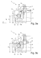
- the workpiece carrier 8 is seconded to a workpiece loading height H 1 of about 1000 mm in order to facilitate the manual loading and unloading of the workpieces 2.
- the workpieces 2 are then processed with the cover 19 closed with the tool 17, the chips fall freely.
- a front door of the cover 19 is opened, and the tool 17 is loaded and unloaded via the tool spindle 7 from a front-side tool magazine 20, which is provided above the wall opening 4 on the vertical wall 3.
- the tool magazine 20 is thus inexpensively equipped on the tool spindle 7 with tools 17, and advantageously on a horrbelade abandon H 2 of about 1400 mm.
- the changing of the workpiece carrier 8 can, as in Fig. 3c shown, carried by a crane 21 via an open roof of the cover 19.
- the machine tool shown differs in Fig. 4 shown machine tool 1 only in that here the interrupted by the wall opening 4 horizontal guides 11 are arranged on a horizontal shoulder 40 of the vertical wall 3.
- the machine tools 1 shown can be equipped with even more tool spindles or even with a single tool spindle instead of the two tool spindles 7 shown.
- the vertical wall 3 below the Wall opening 4 and the paragraph 40 can be for a "free chip fall" inside, ie in the Z direction of the tool spindle 7, reset and have a forward sloping sloping slope 41 for discharging the chips.
Landscapes
- Engineering & Computer Science (AREA)
- Mechanical Engineering (AREA)
- Machine Tool Units (AREA)
- Turning (AREA)
Description
Die Erfindung betrifft eine Werkzeugmaschine zur spanenden Bearbeitung von Werkstücken.The invention relates to a machine tool for machining workpieces.
Aus der
Es ist demgegenüber die Aufgabe der Erfindung, eine einfachere, kostengünstigere Werkzeugmaschine bereitzustellen, bei der Verlagerungen zwischen Werkstückseite und Werkzeugseite auch ohne spezialangefertigte Teile wirkungsvoll verhindert werden können.By contrast, it is the object of the invention to provide a simpler, more cost-effective machine tool, in which displacements between the workpiece side and the tool side can be effectively prevented even without custom-made parts.
Diese Aufgabe wird erfindungsgemäß durch eine Werkzeugmaschine mit den Merkmalen von Anspruch 1 gelöst.This object is achieved by a machine tool with the features of
Erfindungsgemäß sind die horizontalen Führungen des Werkstückträgers zu beiden Seiten der Wandöffnung vorgesehen, also durch die Wandöffnung unterbrochen, wodurch die X-Achse zu beiden Seiten der Wandöffnung aufgetrennt ist. Die horizontalen X-Führungen sind also im Bereich des Späneanfalls bzw. für einen "freien Spänefall" unterbrochen. Horizontale X-Führungen unter dem schwenkbaren Werkstückträger sind insbesondere dann nicht erforderlich, solange der Hub der X-Achse deutlich kleiner als die Spannweite des schwenkbaren Werkstückträgers ist. Das ist vor allem bei mehrspindligen Anwendungen gegeben. Die beim Relativverfahren von Werkzeugspindel und Werkstück und insbesondere die beim Bearbeiten des Werkstücks mit dem in der Werkzeugspindel eingespannten Werkzeug in Z-Richtung wirkenden Kräfte werden in die vertikale Wand abgeleitet und dort aufgenommen. Die vertikale Wand kann einstückig als Monoblockwand (z.B. als Gussteil) ausgebildet oder aus mehreren miteinander verbundenen, insbesondere verschweißten Einzelteilen zusammengesetzt sein.According to the horizontal guides of the workpiece carrier are provided on both sides of the wall opening, so interrupted by the wall opening, whereby the X-axis is separated on both sides of the wall opening. The horizontal X-guides are therefore interrupted in the area of the chips or for a "free chip fall". Horizontal X-guides under the pivoting workpiece carrier are not required in particular then, as long as the stroke of the X-axis is significantly smaller than the span of the pivoting workpiece carrier. This is especially true in multi-spindle applications. The forces acting in the relative direction of the tool spindle and the workpiece and in particular the machining of the workpiece with the tool clamped in the tool spindle in the Z direction are diverted into the vertical wall and received there. The vertical wall can be integrally formed as a monobloc wall (eg as a casting) or be composed of several interconnected, in particular welded individual parts.
Besonders bevorzugt ist der Werkstückträger in einem Antriebslager und einem Gegenlager drehbar um eine horizontale Achse gelagert und mittels dieser Antriebs-und Gegenlager auch in X-Richtung verfahrbar geführt. Die beiden Lager und der dazwischen vorgesehene Werkstückträger bilden somit zusammen einen in X-Richtung verfahrbaren Schubverband.Particularly preferably, the workpiece carrier is mounted rotatably in a drive bearing and an abutment about a horizontal axis and guided by means of this drive and counter bearing movable in the X direction. The two bearings and the provided therebetween workpiece carrier thus together form a movable in the X direction pusher.
Weitere Vorteile der Erfindung ergeben sich aus der Beschreibung und der Zeichnung. Ebenso können die vorstehend genannten und die noch weiter aufgeführten Merkmale erfindungsgemäß jeweils einzeln für sich oder zu mehreren in beliebigen Kombinationen Verwendung finden. Die gezeigten und beschriebenen Ausführungsformen sind nicht als abschließende Aufzählung zu verstehen, sondern haben vielmehr beispielhaften Charakter für die Schilderung der Erfindung. Die Erfindung ist in den Figuren schematisch dargestellt, so dass die wesentlichen Merkmale der Erfindung gut zu erkennen ist. Die Darstellungen sind nicht notwendigerweise maßstäblich zu verstehen.Further advantages of the invention will become apparent from the description and the drawings. Likewise, the features mentioned above and those listed further in accordance with the invention can each be used individually for themselves or for several in any desired combinations. The embodiments shown and described are not to be understood as exhaustive enumeration, but rather have exemplary character for the description of the invention. The invention is shown schematically in the figures, so that the essential features of the invention can be clearly seen. The illustrations are not necessarily to scale.
Es zeigt:
- Fig. 1
- die erfindungsgemäße Werkzeugmaschine in perspektivischer Ansicht;
- Fig. 2
- eine Frontansicht auf die in
Fig. 1 gezeigte Werkzeugmaschine, jedoch ohne Y-Z-Schlitten; - Fig. 3
- eine Seitenansicht der in
Fig. 1 gezeigten Werkzeugmaschine beim manuellen Be- und Entladen von Werkstücken (Fig. 3a ), beim manuel-len Werkzeugwechsel (Fig. 3b ) und beim Wechseln eines Werkstück-trägers mittels eines Krans (Fig. 3c ); und - Fig. 4
- eine modifizierte erfindungsgemäße Werkzeugmaschine in perspektivi-scher Ansicht analog zu
Fig. 1 .
- Fig. 1
- the machine tool according to the invention in a perspective view;
- Fig. 2
- a front view of the in
Fig. 1 shown machine tool, but without YZ slide; - Fig. 3
- a side view of in
Fig. 1 shown machine tool during manual loading and unloading of workpieces (Fig. 3a ), during manual tool change (Fig. 3b ) and when changing a workpiece carrier by means of a crane (Fig. 3c ); and - Fig. 4
- a modified machine tool according to the invention in perspective view analogous to
Fig. 1 ,
Die in
Der Y-Schlitten 5 ist in vertikalen Führungen 9 geführt, die an den vertikalen Laibungsflächen 10 der Wandöffnung 4 vorgesehen sind. Alternativ können die vertikalen Führungen 9 auch außen an der Vorder- oder Rückseite der vertikalen Wand 3 vorgesehen sein. Der Werkstückträger 8 ist in X-Richtung in horizontalen Führungen 11 verfahrbar geführt, die an der Vorderseite der vertikalen Wand 3 zu beiden Seiten der Wandöffnung 4 vorgesehen sind und durch die Wandöffnung 4 in linke und rechte Führungsabschnitte aufgeteilt ist. Der Werkstückträger 8 ist durch einen Schwenkbalken 12 gebildet, der drehbar um eine zu den horizontalen Führungen 11 parallele horizontale Achse A in einem Antriebslager 13a und einem Gegenlager 13b gelagert ist, welche wiederum in den horizontalen Führungen 11 in X-Richtung verfahrbar geführt sind. Genauer gesagt ist das Antriebslager 13a im linken und das Gegenlager 13b im rechten Führungsabschnitt geführt. Die beiden Lager 13a, 13b und der dazwischen vorgesehene Schwenkbalken 12 bilden somit zusammen einen Schubverband. Der Spindelmotor zum Verfahren des Y-Schlittens 5 ist mit 14, der Spindelmotor zum Verfahren des Antriebslagers 13a mit 15 und der Spindelmotor zum Verfahren des Z-Schlittens 6 ist mit 16 (
Die vertikale Wand 3 kann, wie in
Zum Be- und Entladen von Werkstücken 2 durch den Bediener wird, wie in
Zum Werkzeugwechsel durch den Bediener wird, wie in
Das Wechseln des Werkstückträgers 8 kann, wie in
Von der in
Die gezeigten Werkzeugmaschinen 1 können anstatt mit den gezeigten zwei Werkzeugspindeln 7 auch mit noch weiteren Werkzeugspindeln oder auch nur mit einer einzigen Werkzeugspindel ausgestattet sein. Die vertikale Wand 3 unterhalb der Wandöffnung 4 bzw. der Absatz 40 können für einen "freien Spänefall" nach innen, also in Z-Richtung der Werkzeugspindel 7, zurückgesetzt sein und eine nach vorne schräg abfallende Schräge 41 zum Abführen der Späne der aufweisen.The
Claims (9)
- Machine tool (1) for machining workpieces (2), comprising:a vertical wall (3) with a wall opening (4),a Y carriage (5), which can be vertically moved within the wall opening (4), is guided in such a manner that it can be moved along the vertical wall (3), andcarries a Z carriage (6), which can be horizontally moved and comprises at least one horizontal tool spindle (7),characterized in that it comprises a workpiece carrier (8), which is disposed in front of the wall opening (4) and can be horizontally moved in X direction, the horizontal guidances (11) of which are provided at the outside of the vertical wall (3) or on a shoulder (40), in particular a horizontal shoulder, of the vertical wall (3), and are interrupted by the wall opening (4).
- Machine tool according to claim 1, characterized in that the vertical wall (3) is formed in one piece and is, in particular, a cast piece.
- Machine tool according to claim 1, characterized in that the vertical wall (3) is formed from several interconnected, in particular, welded individual parts.
- Machine tool according to any one of the preceding claims, characterized in that the vertical guidances (9) of the Y carriage (5) are provided at the outside of the vertical wall (3) or on the embrasure surfaces (10) of the wall opening (4).
- Machine tool according to any one of the preceding claims, characterized in that the workpiece carrier (8) is supported in a drive bearing (13a) and a counter bearing (13b) in such a manner that it can be rotated about a horizontal axis (A) and is guided in such a manner that it can be moved in X direction by means of the drive and counter bearings (13a, 13b).
- Machine tool according to any one of the preceding claims, characterized in that the workpiece carrier (8) is covered to the front and to the top by means of a cover (19) that can be opened at the front and/or at the top.
- Machine tool according to any one of the preceding claims, characterized in that a tool magazine (20) is provided on the vertical wall (3), in particular, above the wall opening (4).
- Machine tool according to any one of the preceding claims, characterized in that the vertical wall (3) is recessed below the wall opening (4).
- Machine tool according to any one of the preceding claims, characterized in that below the wall opening (4), the vertical wall (3) or the horizontal shoulder (40) has an inclined surface (41) sloping downward to the front.
Priority Applications (3)
| Application Number | Priority Date | Filing Date | Title |
|---|---|---|---|
| ES11165656T ES2431544T3 (en) | 2011-05-11 | 2011-05-11 | Machine tool with a monobloc wall for tool spindle and workpiece carrier |
| EP20110165656 EP2522457B1 (en) | 2011-05-11 | 2011-05-11 | Machine tool with a monoblock wall for tool spindle and workpiece holder |
| CN201210205549.5A CN102773717B (en) | 2011-05-11 | 2012-05-10 | There is the lathe of the integral wall for cutter spindle and work rest |
Applications Claiming Priority (1)
| Application Number | Priority Date | Filing Date | Title |
|---|---|---|---|
| EP20110165656 EP2522457B1 (en) | 2011-05-11 | 2011-05-11 | Machine tool with a monoblock wall for tool spindle and workpiece holder |
Publications (2)
| Publication Number | Publication Date |
|---|---|
| EP2522457A1 EP2522457A1 (en) | 2012-11-14 |
| EP2522457B1 true EP2522457B1 (en) | 2013-07-31 |
Family
ID=44583926
Family Applications (1)
| Application Number | Title | Priority Date | Filing Date |
|---|---|---|---|
| EP20110165656 Active EP2522457B1 (en) | 2011-05-11 | 2011-05-11 | Machine tool with a monoblock wall for tool spindle and workpiece holder |
Country Status (3)
| Country | Link |
|---|---|
| EP (1) | EP2522457B1 (en) |
| CN (1) | CN102773717B (en) |
| ES (1) | ES2431544T3 (en) |
Families Citing this family (1)
| Publication number | Priority date | Publication date | Assignee | Title |
|---|---|---|---|---|
| FR3058347A1 (en) * | 2016-11-10 | 2018-05-11 | Comau France | MACHINE-TOOL MACHINING |
Family Cites Families (6)
| Publication number | Priority date | Publication date | Assignee | Title |
|---|---|---|---|---|
| DE4230502C1 (en) * | 1992-09-14 | 1994-03-10 | Steinel Bernhard Werkzeugmasch | Machine frame for a machining center |
| DE19639527C1 (en) | 1996-09-26 | 1998-04-09 | Hueller Hille Gmbh | Machine tool for machining with horizontally arranged work spindle |
| EP1186371A1 (en) * | 2000-09-08 | 2002-03-13 | Mikron Comp-Tec AG | Portal Milling Machine |
| CN2810870Y (en) * | 2005-06-29 | 2006-08-30 | 山东鲁南机床有限公司 | Central transmission mechanism for milling machine table |
| DE102008003397A1 (en) * | 2008-01-08 | 2009-07-09 | MAG Industrial Automation Systems, LLC., Sterling Heights | Machine frame for a machine tool |
| ES2392651T3 (en) * | 2008-02-29 | 2012-12-12 | Horkos Corp | Machine tool |
-
2011
- 2011-05-11 EP EP20110165656 patent/EP2522457B1/en active Active
- 2011-05-11 ES ES11165656T patent/ES2431544T3/en active Active
-
2012
- 2012-05-10 CN CN201210205549.5A patent/CN102773717B/en active Active
Also Published As
| Publication number | Publication date |
|---|---|
| ES2431544T3 (en) | 2013-11-26 |
| EP2522457A1 (en) | 2012-11-14 |
| CN102773717A (en) | 2012-11-14 |
| CN102773717B (en) | 2016-04-06 |
Similar Documents
| Publication | Publication Date | Title |
|---|---|---|
| EP2658676B1 (en) | Program-controlled machine tool | |
| DE102012002982B4 (en) | Machine tool with A-axis | |
| DE3139962C2 (en) | Machine tool with chip conveyor | |
| DE112008000973T5 (en) | machine tool | |
| EP1216779B1 (en) | Machine tool, in particular electroerosion machine and modular construction assembly | |
| DE102007042288A1 (en) | Machine tool, has multiple tool spindle heads supported in machine rack and workpiece carrier, which is displaced along guidance and machine frame has closed frame with regard to force flow | |
| EP1616661B1 (en) | Machine tool with workpiece changing device | |
| DE102007054268A1 (en) | Multi-spindle machine | |
| DE602004001733T2 (en) | Horizontal Machining Center | |
| DE102013216752A1 (en) | Machine tool | |
| DE19732608B4 (en) | machine tool | |
| DE102010007889B4 (en) | Machine tool with swivel head | |
| DE102008063513B4 (en) | machining center | |
| EP2522457B1 (en) | Machine tool with a monoblock wall for tool spindle and workpiece holder | |
| DE102008011668B4 (en) | Broaching | |
| EP2875879B1 (en) | Mechanical workpiece transfer device and mechanical unloading device and mechanical assembly for the machining of workpieces with such a workpiece transfer device | |
| EP1186372B1 (en) | Portal milling machine | |
| DE102007054267A1 (en) | Multi-spindle machine | |
| EP1137508B1 (en) | Machine tool with a horizontal work spindle | |
| DE102005058347A1 (en) | Machine tool with loading device | |
| EP1621284A1 (en) | Workpiece changing device for machine tools | |
| DE602006000844T2 (en) | Loading device for a machine tool or a workstation and workstation with such a loading device | |
| DE19857013A1 (en) | Machine tool with horizontal work spindle | |
| EP1618987B1 (en) | Horizontal machine tool with fixed working spindle in U-shaped frame | |
| DE10252710B4 (en) | lathe |
Legal Events
| Date | Code | Title | Description |
|---|---|---|---|
| PUAI | Public reference made under article 153(3) epc to a published international application that has entered the european phase |
Free format text: ORIGINAL CODE: 0009012 |
|
| AK | Designated contracting states |
Kind code of ref document: A1 Designated state(s): AL AT BE BG CH CY CZ DE DK EE ES FI FR GB GR HR HU IE IS IT LI LT LU LV MC MK MT NL NO PL PT RO RS SE SI SK SM TR |
|
| AX | Request for extension of the european patent |
Extension state: BA ME |
|
| GRAP | Despatch of communication of intention to grant a patent |
Free format text: ORIGINAL CODE: EPIDOSNIGR1 |
|
| 17P | Request for examination filed |
Effective date: 20130312 |
|
| RIC1 | Information provided on ipc code assigned before grant |
Ipc: B23Q 1/01 20060101AFI20130403BHEP |
|
| INTG | Intention to grant announced |
Effective date: 20130418 |
|
| GRAS | Grant fee paid |
Free format text: ORIGINAL CODE: EPIDOSNIGR3 |
|
| GRAA | (expected) grant |
Free format text: ORIGINAL CODE: 0009210 |
|
| AK | Designated contracting states |
Kind code of ref document: B1 Designated state(s): AL AT BE BG CH CY CZ DE DK EE ES FI FR GB GR HR HU IE IS IT LI LT LU LV MC MK MT NL NO PL PT RO RS SE SI SK SM TR |
|
| REG | Reference to a national code |
Ref country code: GB Ref legal event code: FG4D Free format text: NOT ENGLISH Ref country code: CH Ref legal event code: EP |
|
| REG | Reference to a national code |
Ref country code: AT Ref legal event code: REF Ref document number: 624324 Country of ref document: AT Kind code of ref document: T Effective date: 20130815 |
|
| REG | Reference to a national code |
Ref country code: IE Ref legal event code: FG4D Free format text: LANGUAGE OF EP DOCUMENT: GERMAN |
|
| REG | Reference to a national code |
Ref country code: DE Ref legal event code: R096 Ref document number: 502011001121 Country of ref document: DE Effective date: 20130919 |
|
| REG | Reference to a national code |
Ref country code: ES Ref legal event code: FG2A Ref document number: 2431544 Country of ref document: ES Kind code of ref document: T3 Effective date: 20131126 |
|
| REG | Reference to a national code |
Ref country code: NL Ref legal event code: VDEP Effective date: 20130731 |
|
| REG | Reference to a national code |
Ref country code: LT Ref legal event code: MG4D |
|
| PG25 | Lapsed in a contracting state [announced via postgrant information from national office to epo] |
Ref country code: SE Free format text: LAPSE BECAUSE OF FAILURE TO SUBMIT A TRANSLATION OF THE DESCRIPTION OR TO PAY THE FEE WITHIN THE PRESCRIBED TIME-LIMIT Effective date: 20130731 Ref country code: CY Free format text: LAPSE BECAUSE OF FAILURE TO SUBMIT A TRANSLATION OF THE DESCRIPTION OR TO PAY THE FEE WITHIN THE PRESCRIBED TIME-LIMIT Effective date: 20130918 Ref country code: NO Free format text: LAPSE BECAUSE OF FAILURE TO SUBMIT A TRANSLATION OF THE DESCRIPTION OR TO PAY THE FEE WITHIN THE PRESCRIBED TIME-LIMIT Effective date: 20131031 Ref country code: IS Free format text: LAPSE BECAUSE OF FAILURE TO SUBMIT A TRANSLATION OF THE DESCRIPTION OR TO PAY THE FEE WITHIN THE PRESCRIBED TIME-LIMIT Effective date: 20131130 Ref country code: PT Free format text: LAPSE BECAUSE OF FAILURE TO SUBMIT A TRANSLATION OF THE DESCRIPTION OR TO PAY THE FEE WITHIN THE PRESCRIBED TIME-LIMIT Effective date: 20131202 Ref country code: LT Free format text: LAPSE BECAUSE OF FAILURE TO SUBMIT A TRANSLATION OF THE DESCRIPTION OR TO PAY THE FEE WITHIN THE PRESCRIBED TIME-LIMIT Effective date: 20130731 Ref country code: HR Free format text: LAPSE BECAUSE OF FAILURE TO SUBMIT A TRANSLATION OF THE DESCRIPTION OR TO PAY THE FEE WITHIN THE PRESCRIBED TIME-LIMIT Effective date: 20130731 |
|
| PG25 | Lapsed in a contracting state [announced via postgrant information from national office to epo] |
Ref country code: PL Free format text: LAPSE BECAUSE OF FAILURE TO SUBMIT A TRANSLATION OF THE DESCRIPTION OR TO PAY THE FEE WITHIN THE PRESCRIBED TIME-LIMIT Effective date: 20130731 Ref country code: GR Free format text: LAPSE BECAUSE OF FAILURE TO SUBMIT A TRANSLATION OF THE DESCRIPTION OR TO PAY THE FEE WITHIN THE PRESCRIBED TIME-LIMIT Effective date: 20131101 Ref country code: LV Free format text: LAPSE BECAUSE OF FAILURE TO SUBMIT A TRANSLATION OF THE DESCRIPTION OR TO PAY THE FEE WITHIN THE PRESCRIBED TIME-LIMIT Effective date: 20130731 Ref country code: FI Free format text: LAPSE BECAUSE OF FAILURE TO SUBMIT A TRANSLATION OF THE DESCRIPTION OR TO PAY THE FEE WITHIN THE PRESCRIBED TIME-LIMIT Effective date: 20130731 Ref country code: NL Free format text: LAPSE BECAUSE OF FAILURE TO SUBMIT A TRANSLATION OF THE DESCRIPTION OR TO PAY THE FEE WITHIN THE PRESCRIBED TIME-LIMIT Effective date: 20130731 |
|
| PG25 | Lapsed in a contracting state [announced via postgrant information from national office to epo] |
Ref country code: CY Free format text: LAPSE BECAUSE OF FAILURE TO SUBMIT A TRANSLATION OF THE DESCRIPTION OR TO PAY THE FEE WITHIN THE PRESCRIBED TIME-LIMIT Effective date: 20130731 |
|
| PG25 | Lapsed in a contracting state [announced via postgrant information from national office to epo] |
Ref country code: RO Free format text: LAPSE BECAUSE OF FAILURE TO SUBMIT A TRANSLATION OF THE DESCRIPTION OR TO PAY THE FEE WITHIN THE PRESCRIBED TIME-LIMIT Effective date: 20130731 Ref country code: EE Free format text: LAPSE BECAUSE OF FAILURE TO SUBMIT A TRANSLATION OF THE DESCRIPTION OR TO PAY THE FEE WITHIN THE PRESCRIBED TIME-LIMIT Effective date: 20130731 Ref country code: CZ Free format text: LAPSE BECAUSE OF FAILURE TO SUBMIT A TRANSLATION OF THE DESCRIPTION OR TO PAY THE FEE WITHIN THE PRESCRIBED TIME-LIMIT Effective date: 20130731 Ref country code: SK Free format text: LAPSE BECAUSE OF FAILURE TO SUBMIT A TRANSLATION OF THE DESCRIPTION OR TO PAY THE FEE WITHIN THE PRESCRIBED TIME-LIMIT Effective date: 20130731 Ref country code: DK Free format text: LAPSE BECAUSE OF FAILURE TO SUBMIT A TRANSLATION OF THE DESCRIPTION OR TO PAY THE FEE WITHIN THE PRESCRIBED TIME-LIMIT Effective date: 20130731 |
|
| PLBE | No opposition filed within time limit |
Free format text: ORIGINAL CODE: 0009261 |
|
| STAA | Information on the status of an ep patent application or granted ep patent |
Free format text: STATUS: NO OPPOSITION FILED WITHIN TIME LIMIT |
|
| 26N | No opposition filed |
Effective date: 20140502 |
|
| REG | Reference to a national code |
Ref country code: DE Ref legal event code: R097 Ref document number: 502011001121 Country of ref document: DE Effective date: 20140502 |
|
| PG25 | Lapsed in a contracting state [announced via postgrant information from national office to epo] |
Ref country code: LU Free format text: LAPSE BECAUSE OF FAILURE TO SUBMIT A TRANSLATION OF THE DESCRIPTION OR TO PAY THE FEE WITHIN THE PRESCRIBED TIME-LIMIT Effective date: 20140511 |
|
| REG | Reference to a national code |
Ref country code: CH Ref legal event code: PL |
|
| PG25 | Lapsed in a contracting state [announced via postgrant information from national office to epo] |
Ref country code: CH Free format text: LAPSE BECAUSE OF NON-PAYMENT OF DUE FEES Effective date: 20140531 Ref country code: MC Free format text: LAPSE BECAUSE OF FAILURE TO SUBMIT A TRANSLATION OF THE DESCRIPTION OR TO PAY THE FEE WITHIN THE PRESCRIBED TIME-LIMIT Effective date: 20130731 Ref country code: LI Free format text: LAPSE BECAUSE OF NON-PAYMENT OF DUE FEES Effective date: 20140531 |
|
| REG | Reference to a national code |
Ref country code: IE Ref legal event code: MM4A |
|
| PG25 | Lapsed in a contracting state [announced via postgrant information from national office to epo] |
Ref country code: IE Free format text: LAPSE BECAUSE OF NON-PAYMENT OF DUE FEES Effective date: 20140511 |
|
| GBPC | Gb: european patent ceased through non-payment of renewal fee |
Effective date: 20150511 |
|
| PG25 | Lapsed in a contracting state [announced via postgrant information from national office to epo] |
Ref country code: MT Free format text: LAPSE BECAUSE OF FAILURE TO SUBMIT A TRANSLATION OF THE DESCRIPTION OR TO PAY THE FEE WITHIN THE PRESCRIBED TIME-LIMIT Effective date: 20130731 |
|
| PG25 | Lapsed in a contracting state [announced via postgrant information from national office to epo] |
Ref country code: GB Free format text: LAPSE BECAUSE OF NON-PAYMENT OF DUE FEES Effective date: 20150511 Ref country code: SM Free format text: LAPSE BECAUSE OF FAILURE TO SUBMIT A TRANSLATION OF THE DESCRIPTION OR TO PAY THE FEE WITHIN THE PRESCRIBED TIME-LIMIT Effective date: 20130731 |
|
| REG | Reference to a national code |
Ref country code: FR Ref legal event code: PLFP Year of fee payment: 6 |
|
| PG25 | Lapsed in a contracting state [announced via postgrant information from national office to epo] |
Ref country code: RS Free format text: LAPSE BECAUSE OF NON-PAYMENT OF DUE FEES Effective date: 20130731 Ref country code: BG Free format text: LAPSE BECAUSE OF FAILURE TO SUBMIT A TRANSLATION OF THE DESCRIPTION OR TO PAY THE FEE WITHIN THE PRESCRIBED TIME-LIMIT Effective date: 20130731 |
|
| PG25 | Lapsed in a contracting state [announced via postgrant information from national office to epo] |
Ref country code: BE Free format text: LAPSE BECAUSE OF FAILURE TO SUBMIT A TRANSLATION OF THE DESCRIPTION OR TO PAY THE FEE WITHIN THE PRESCRIBED TIME-LIMIT Effective date: 20140531 Ref country code: SI Free format text: LAPSE BECAUSE OF FAILURE TO SUBMIT A TRANSLATION OF THE DESCRIPTION OR TO PAY THE FEE WITHIN THE PRESCRIBED TIME-LIMIT Effective date: 20130731 Ref country code: TR Free format text: LAPSE BECAUSE OF FAILURE TO SUBMIT A TRANSLATION OF THE DESCRIPTION OR TO PAY THE FEE WITHIN THE PRESCRIBED TIME-LIMIT Effective date: 20130731 Ref country code: HU Free format text: LAPSE BECAUSE OF FAILURE TO SUBMIT A TRANSLATION OF THE DESCRIPTION OR TO PAY THE FEE WITHIN THE PRESCRIBED TIME-LIMIT; INVALID AB INITIO Effective date: 20110511 |
|
| REG | Reference to a national code |
Ref country code: FR Ref legal event code: PLFP Year of fee payment: 7 |
|
| REG | Reference to a national code |
Ref country code: AT Ref legal event code: MM01 Ref document number: 624324 Country of ref document: AT Kind code of ref document: T Effective date: 20160511 |
|
| PG25 | Lapsed in a contracting state [announced via postgrant information from national office to epo] |
Ref country code: AT Free format text: LAPSE BECAUSE OF NON-PAYMENT OF DUE FEES Effective date: 20160511 |
|
| REG | Reference to a national code |
Ref country code: FR Ref legal event code: PLFP Year of fee payment: 8 |
|
| PG25 | Lapsed in a contracting state [announced via postgrant information from national office to epo] |
Ref country code: MK Free format text: LAPSE BECAUSE OF FAILURE TO SUBMIT A TRANSLATION OF THE DESCRIPTION OR TO PAY THE FEE WITHIN THE PRESCRIBED TIME-LIMIT Effective date: 20130731 |
|
| PG25 | Lapsed in a contracting state [announced via postgrant information from national office to epo] |
Ref country code: AL Free format text: LAPSE BECAUSE OF FAILURE TO SUBMIT A TRANSLATION OF THE DESCRIPTION OR TO PAY THE FEE WITHIN THE PRESCRIBED TIME-LIMIT Effective date: 20130731 |
|
| PGFP | Annual fee paid to national office [announced via postgrant information from national office to epo] |
Ref country code: DE Payment date: 20240523 Year of fee payment: 14 |
|
| PGFP | Annual fee paid to national office [announced via postgrant information from national office to epo] |
Ref country code: ES Payment date: 20240614 Year of fee payment: 14 |
|
| PGFP | Annual fee paid to national office [announced via postgrant information from national office to epo] |
Ref country code: FR Payment date: 20240516 Year of fee payment: 14 |
|
| PGFP | Annual fee paid to national office [announced via postgrant information from national office to epo] |
Ref country code: IT Payment date: 20240531 Year of fee payment: 14 |