EP2522254A1 - A soft ending of opening movement device - Google Patents
A soft ending of opening movement device Download PDFInfo
- Publication number
- EP2522254A1 EP2522254A1 EP12179999A EP12179999A EP2522254A1 EP 2522254 A1 EP2522254 A1 EP 2522254A1 EP 12179999 A EP12179999 A EP 12179999A EP 12179999 A EP12179999 A EP 12179999A EP 2522254 A1 EP2522254 A1 EP 2522254A1
- Authority
- EP
- European Patent Office
- Prior art keywords
- rocker
- damper
- opening movement
- pin
- movement device
- Prior art date
- Legal status (The legal status is an assumption and is not a legal conclusion. Google has not performed a legal analysis and makes no representation as to the accuracy of the status listed.)
- Ceased
Links
Images
Classifications
-
- E—FIXED CONSTRUCTIONS
- E05—LOCKS; KEYS; WINDOW OR DOOR FITTINGS; SAFES
- E05F—DEVICES FOR MOVING WINGS INTO OPEN OR CLOSED POSITION; CHECKS FOR WINGS; WING FITTINGS NOT OTHERWISE PROVIDED FOR, CONCERNED WITH THE FUNCTIONING OF THE WING
- E05F1/00—Closers or openers for wings, not otherwise provided for in this subclass
- E05F1/08—Closers or openers for wings, not otherwise provided for in this subclass spring-actuated, e.g. for horizontally sliding wings
- E05F1/16—Closers or openers for wings, not otherwise provided for in this subclass spring-actuated, e.g. for horizontally sliding wings for sliding wings
-
- A—HUMAN NECESSITIES
- A47—FURNITURE; DOMESTIC ARTICLES OR APPLIANCES; COFFEE MILLS; SPICE MILLS; SUCTION CLEANERS IN GENERAL
- A47B—TABLES; DESKS; OFFICE FURNITURE; CABINETS; DRAWERS; GENERAL DETAILS OF FURNITURE
- A47B88/00—Drawers for tables, cabinets or like furniture; Guides for drawers
- A47B88/40—Sliding drawers; Slides or guides therefor
- A47B88/453—Actuated drawers
- A47B88/46—Actuated drawers operated by mechanically-stored energy, e.g. by springs
- A47B88/47—Actuated drawers operated by mechanically-stored energy, e.g. by springs having both self-opening and self-closing mechanisms which interact with each other
-
- A—HUMAN NECESSITIES
- A47—FURNITURE; DOMESTIC ARTICLES OR APPLIANCES; COFFEE MILLS; SPICE MILLS; SUCTION CLEANERS IN GENERAL
- A47B—TABLES; DESKS; OFFICE FURNITURE; CABINETS; DRAWERS; GENERAL DETAILS OF FURNITURE
- A47B2210/00—General construction of drawers, guides and guide devices
- A47B2210/0091—Drawer movement damping
- A47B2210/0094—Drawer damping device with 2 relatively movable parts to convert kinetic energy
-
- E—FIXED CONSTRUCTIONS
- E05—LOCKS; KEYS; WINDOW OR DOOR FITTINGS; SAFES
- E05Y—INDEXING SCHEME ASSOCIATED WITH SUBCLASSES E05D AND E05F, RELATING TO CONSTRUCTION ELEMENTS, ELECTRIC CONTROL, POWER SUPPLY, POWER SIGNAL OR TRANSMISSION, USER INTERFACES, MOUNTING OR COUPLING, DETAILS, ACCESSORIES, AUXILIARY OPERATIONS NOT OTHERWISE PROVIDED FOR, APPLICATION THEREOF
- E05Y2201/00—Constructional elements; Accessories therefor
- E05Y2201/20—Brakes; Disengaging means; Holders; Stops; Valves; Accessories therefor
- E05Y2201/21—Brakes
-
- E—FIXED CONSTRUCTIONS
- E05—LOCKS; KEYS; WINDOW OR DOOR FITTINGS; SAFES
- E05Y—INDEXING SCHEME ASSOCIATED WITH SUBCLASSES E05D AND E05F, RELATING TO CONSTRUCTION ELEMENTS, ELECTRIC CONTROL, POWER SUPPLY, POWER SIGNAL OR TRANSMISSION, USER INTERFACES, MOUNTING OR COUPLING, DETAILS, ACCESSORIES, AUXILIARY OPERATIONS NOT OTHERWISE PROVIDED FOR, APPLICATION THEREOF
- E05Y2201/00—Constructional elements; Accessories therefor
- E05Y2201/20—Brakes; Disengaging means; Holders; Stops; Valves; Accessories therefor
- E05Y2201/252—Type of friction
- E05Y2201/254—Fluid or viscous friction
- E05Y2201/256—Fluid or viscous friction with pistons or vanes
-
- E—FIXED CONSTRUCTIONS
- E05—LOCKS; KEYS; WINDOW OR DOOR FITTINGS; SAFES
- E05Y—INDEXING SCHEME ASSOCIATED WITH SUBCLASSES E05D AND E05F, RELATING TO CONSTRUCTION ELEMENTS, ELECTRIC CONTROL, POWER SUPPLY, POWER SIGNAL OR TRANSMISSION, USER INTERFACES, MOUNTING OR COUPLING, DETAILS, ACCESSORIES, AUXILIARY OPERATIONS NOT OTHERWISE PROVIDED FOR, APPLICATION THEREOF
- E05Y2201/00—Constructional elements; Accessories therefor
- E05Y2201/20—Brakes; Disengaging means; Holders; Stops; Valves; Accessories therefor
- E05Y2201/262—Type of motion, e.g. braking
- E05Y2201/264—Type of motion, e.g. braking linear
-
- E—FIXED CONSTRUCTIONS
- E05—LOCKS; KEYS; WINDOW OR DOOR FITTINGS; SAFES
- E05Y—INDEXING SCHEME ASSOCIATED WITH SUBCLASSES E05D AND E05F, RELATING TO CONSTRUCTION ELEMENTS, ELECTRIC CONTROL, POWER SUPPLY, POWER SIGNAL OR TRANSMISSION, USER INTERFACES, MOUNTING OR COUPLING, DETAILS, ACCESSORIES, AUXILIARY OPERATIONS NOT OTHERWISE PROVIDED FOR, APPLICATION THEREOF
- E05Y2201/00—Constructional elements; Accessories therefor
- E05Y2201/40—Motors; Magnets; Springs; Weights; Accessories therefor
- E05Y2201/404—Function thereof
- E05Y2201/422—Function thereof for opening
- E05Y2201/424—Function thereof for opening for the final opening movement
-
- E—FIXED CONSTRUCTIONS
- E05—LOCKS; KEYS; WINDOW OR DOOR FITTINGS; SAFES
- E05Y—INDEXING SCHEME ASSOCIATED WITH SUBCLASSES E05D AND E05F, RELATING TO CONSTRUCTION ELEMENTS, ELECTRIC CONTROL, POWER SUPPLY, POWER SIGNAL OR TRANSMISSION, USER INTERFACES, MOUNTING OR COUPLING, DETAILS, ACCESSORIES, AUXILIARY OPERATIONS NOT OTHERWISE PROVIDED FOR, APPLICATION THEREOF
- E05Y2900/00—Application of doors, windows, wings or fittings thereof
- E05Y2900/20—Application of doors, windows, wings or fittings thereof for furniture, e.g. cabinets
Definitions
- the invention relates to a device for securing a soft ending of the opening movement of a drawer as the latter is drawn towards an outer limit stop, the drawer being mounted in a furniture body and capable of being pulled out from said body, and in which there may be one or more rails between the drawer and the furniture body.
- a spring mechanism used for the ending of the closing movement of a drawer mounted in a furniture body is known from prior art. However, the reliability of the mechanism is not sufficient when it comes to opening the drawer.
- the purpose of the invention is to indicate a device of the type mentioned above, which is particularly reliable when it comes to opening a drawer in a furniture body.
- the device according to the invention is characterised in that it comprises a damper filled with a fluid medium, such as air, gas, oil, water or other types of liquids, attached to the furniture body - or to a rail of the furniture body - and a piston with a piston rod being reciprocable in said damper, the free end of the piston rod being attached to a tilt-able rocker, and where the rocker, whenever the piston rod is moved in and out in the damper, can be moved on a guide portion - mounted at the damper - between a first end position close to the damper, in which a first pin mounted at the back of the drawer may engage with the rocker, and a second end position far from the damper, in which the piston rod is in its outermost position.
- a fluid medium such as air, gas, oil, water or other types of liquids
- a coil spring may be mounted around the piston rod on the part that lies between the damper and the rocker.
- the coil spring may be mounted within the damper between the piston and a bottom piece in the damper.
- the rocker may also have at least one supporting element, which is placed across the principal plane of the rocker and which preferably is constituted of at least one main pin.
- the rocker may have two main pins placed at a distance from each other of more than 1.2 - possibly more than 1.3 - times the width of said first pin.
- said first pin in a particularly reliable way may engage with said main pins.
- one or two auxiliary pins are arranged at a level under the main pin of the rocker, said auxiliary pin or pins being adapted so as to slide through a longitudinal - possibly open-worked - groove in the guide portion, said groove at one end having a curved groove portion in order to provide a turning of the rocker, when at least one of the auxiliary pins of the rocker has reached the curved groove portion.
- a horizontal supporting surface for the main pin(s) on the top side of the guide portion said supporting surface having a depression on the spot closest to the damper, and in which a main pin can slide in, when the drawer is closed.
- the two auxiliary pins of the rocker are placed at such a distance from each other that only one of the auxiliary pins can slide into the curved groove portion.
- the rocker may be connected to the outer end of the piston rod by means of a supporting element, which preferably is guided in a slot in the guide portion, the supporting element for example being equipped with a thickened part, which can keep the supporting element in place in the slot.
- a particularly reliable steering of the outer end of the piston rod is achieved, which results in a more reliable device.
- the damper, the guide portion and the rocker may be made of plastic, preferably Acetal® or polyamide.
- plastic preferably Acetal® or polyamide.
- the coil spring may be a pressure spring.
- the pressure spring will be entirely relaxed.
- a device for automatically securing a soft ending of the closing movement of the drawer in the furniture body a second pin mounted on the drawer - or on its rail - during the inward movement of the drawer being capable of engaging a second tilt-able rocker that is mounted at the end of a second piston rod in a second damper, said second pin being arranged so as to function in a plane parallel to the plane in which the first pin is functioning.
- a second coil spring preferably a tension spring, near the second piston rod, preferably parallel hereto.
- the device shown in Fig. 1 is intended for the mounting of a drawer in a furniture body. Neither the drawer nor the furniture body is shown. However, the drawer is mounted right on top of the top side of a rail 1. The drawer may, when it is opened, be moved to the left as shown by arrow A in Fig. 2 .
- the rail 1 is attached to and may be displaced in relation to a lower rail 3 that is attached to a vertical wall in the not-shown drawer hole in the not-shown furniture body.
- Fig. 1 and 2 show how the device at the left end of the rail 3 - and thus attached to the furniture body - is furnished with a damper 6 containing a fluid medium with some degree of viscosity, for example gas, oil or water. However, the medium may also be air.
- a not-shown piston is mounted, which is connected to a piston rod 7 as shown in Fig. 2 .
- the not-shown piston can perform a back-and-forward movement within the damper 6.
- the outer free end of the piston rod 7 is connected with a rocker 9.
- Fig. 2 shows the rocker 9 in a first end position close to the damper 6.
- a first pin 19 mounted at the end of the rail 1
- the rocker 9 can be turned from the position shown in Fig. 2 to the position shown in Fig. 3 .
- the first pin 19 and herewith the pull-out rail 1 and the corresponding drawer cannot keep on moving further to the left due to a limit stop 10 and the fact that the piston rod 7 is limited in size.
- a coil spring 11 which can secure a not too fast pulling out of the drawer, i.e. a not too fast movement of the drawer to the left, at the final stage of the opening of the drawer (the pulling out).
- the coil spring 11 might be mounted within the damper 6. In this case the coil spring may be arranged between the not-shown piston of the damper and the damper bottom piece 34 facing away from the piston rod.
- Fig. 2 shows how the rocker 9 may have a supporting element, which is placed across the principal plane of the rocker - here in the form of two main pins 12, 13.
- the second of the two main pins is indicated by a dotted line only, since it is situated behind the rocker 9.
- the distance X between the main pins 12, 13 is preferably larger than 1.2 - for example 1.3 - times the width of the pin 19.
- the rocker 9 has also two auxiliary pins 12a, 13a, which can slide through a groove 18 in the guide portion 17. As shown in Fig. 2 and Fig. 4 , the second auxiliary pin 13a may have slid down into the curved groove portion 18a in the guide portion 17.
- the auxiliary tap 13a can be moved upwards and rest on a wall 18b in a horizontal groove or slot 18 in the guide portion 17. Also the first auxiliary pin 12a can slide in this groove 18. It should be noted that simultaneously with the auxiliary pin 13a being moved downwards in the curved groove portion 18a, the main pin 13 will finally slide down into a depression 35 in the guide portion 17.
- the damper 6, the guide portion 17 and the rocker 9 may for example be made of plastic, preferably Acetal® or polyamide.
- the coil spring 11 referred to is preferably a pressure spring.
- the rocker 9 may be connected to the outer end of the piston rod 7 by means of a supporting element 33, which slides in a slot 32 in the guide portion 17.
- the supporting element 33 may have a thickened part 37, which can secure the supporting element 33 in the slot 32.
- the supporting element 33 may have a mainly V-shaped cross section.
- a device 25 possibly rather deep inside the furniture body, namely on the rail 3.
- This device automatically secures a soft ending of the closing movement of the drawer in the not-shown furniture body.
- a second pin 27 on the pull-out rail 1 which, whenever the drawer is pushed inwards closing the drawer, can engage with a second tilt-able rocker 29 mounted on a second piston rod in a second damper 31.
- This second pin 27 is arranged so as to function in a plane parallel to the plane in which the first pin functions.
- the plane in which the second pin 27 functions is situated a bit further away from the reader's point of view than the plane in which the first pin 19 functions.
- a second coil spring which - in the same way as the first coil spring pushes the first piston rod 7 outwards - can push the second piston rod outwards. Also the second damper 31 can through a fluid medium push the second piston rod outwards.
- the invention may be modified in many ways without deviating from the general idea of the invention.
Landscapes
- Engineering & Computer Science (AREA)
- Mechanical Engineering (AREA)
- Drawers Of Furniture (AREA)
- Fluid-Damping Devices (AREA)
Abstract
Description
- The invention relates to a device for securing a soft ending of the opening movement of a drawer as the latter is drawn towards an outer limit stop, the drawer being mounted in a furniture body and capable of being pulled out from said body, and in which there may be one or more rails between the drawer and the furniture body.
- A spring mechanism used for the ending of the closing movement of a drawer mounted in a furniture body is known from prior art. However, the reliability of the mechanism is not sufficient when it comes to opening the drawer.
- The purpose of the invention is to indicate a device of the type mentioned above, which is particularly reliable when it comes to opening a drawer in a furniture body.
- The device according to the invention is characterised in that it comprises a damper filled with a fluid medium, such as air, gas, oil, water or other types of liquids, attached to the furniture body - or to a rail of the furniture body - and a piston with a piston rod being reciprocable in said damper, the free end of the piston rod being attached to a tilt-able rocker, and where the rocker, whenever the piston rod is moved in and out in the damper, can be moved on a guide portion - mounted at the damper - between a first end position close to the damper, in which a first pin mounted at the back of the drawer may engage with the rocker, and a second end position far from the damper, in which the piston rod is in its outermost position. As a result, it is achieved that a user opening the drawer will realise that the drawer goes smoothly. However, as the drawer approaches the outer limit stop, the user will become aware of a gradually increasing resistance to moving the drawer. This makes the device particularly reliable whether or not the drawer is rather heavy or light.
- According to the invention, a coil spring may be mounted around the piston rod on the part that lies between the damper and the rocker. Hereby it is achieved that the drawer - especially in the beginning of the opening process - will give the impression that it goes smoothly. This results from the fact hat the coil spring resists to the forces that might try to keep the drawer in its position, namely frictional forces between the drawer and the furniture body.
- Furthermore, according to the invention the coil spring may be mounted within the damper between the piston and a bottom piece in the damper. Hereby it is also obtained that the movement of the drawer becomes suitably easy, when the drawer is opened.
- According to the invention, the rocker may also have at least one supporting element, which is placed across the principal plane of the rocker and which preferably is constituted of at least one main pin.
- In addition, according to the invention the rocker may have two main pins placed at a distance from each other of more than 1.2 - possibly more than 1.3 - times the width of said first pin. Hereby it is achieved that said first pin in a particularly reliable way may engage with said main pins.
- Additionally, according to the invention one or two auxiliary pins are arranged at a level under the main pin of the rocker, said auxiliary pin or pins being adapted so as to slide through a longitudinal - possibly open-worked - groove in the guide portion, said groove at one end having a curved groove portion in order to provide a turning of the rocker, when at least one of the auxiliary pins of the rocker has reached the curved groove portion. Hereby it is achieved that the drawer is secured particularly efficiently in closed position, since the drawer will not be able to slide unintentionally from the furniture body, if the furniture body by mistake is placed on a rather oblique base.
- Furthermore, according to the invention there may be a horizontal supporting surface for the main pin(s) on the top side of the guide portion, said supporting surface having a depression on the spot closest to the damper, and in which a main pin can slide in, when the drawer is closed. Hereby it is achieved that the drawer is secured particularly reliably, when it is in the furniture body.
- In addition, according to the invention the two auxiliary pins of the rocker are placed at such a distance from each other that only one of the auxiliary pins can slide into the curved groove portion. Hereby it is achieved in a particularly simple way that the drawer is secured reliably in closed position.
- According to the invention the rocker may be connected to the outer end of the piston rod by means of a supporting element, which preferably is guided in a slot in the guide portion, the supporting element for example being equipped with a thickened part, which can keep the supporting element in place in the slot. Hereby a particularly reliable steering of the outer end of the piston rod is achieved, which results in a more reliable device.
- Furthermore, according to the invention the damper, the guide portion and the rocker may be made of plastic, preferably Acetal® or polyamide. Hereby it is achieved that the device becomes both light and strong.
- Additionally, according to the invention the coil spring may be a pressure spring. Hereby it is achieved that the drawer, when it is opened, goes very smoothly. When the drawer is completely opened, the pressure spring will be entirely relaxed.
- Furthermore, according to the invention, at the connection of the drawer and the furniture body there may be mounted a device for automatically securing a soft ending of the closing movement of the drawer in the furniture body, a second pin mounted on the drawer - or on its rail - during the inward movement of the drawer being capable of engaging a second tilt-able rocker that is mounted at the end of a second piston rod in a second damper, said second pin being arranged so as to function in a plane parallel to the plane in which the first pin is functioning. Hereby it is achieved that both the opening and closing procedure of the drawer are very reliable with the effect that a user would not easily lose control over the drawer during the opening and closing procedure.
- Finally, according to the invention there may be mounted a second coil spring, preferably a tension spring, near the second piston rod, preferably parallel hereto. Hereby it is achieved that also the closing of the drawer can be very reliable.
- The invention is explained in detail below with reference to the drawings, in which
-
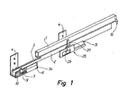
Fig. 1 is a perspective view of a first embodiment of the device according to the invention, an intermediate rail 1, which is attached to the drawer, being pushed in completely; -
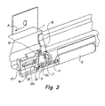
Fig. 2 same, as a rail, which is attached to the drawer, is being pulled out in the direction of arrow A, and a first pin on the rail engages the device; -
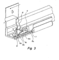
Fig. 3 same, as said first pin - and therefore the drawer - cannot be pulled out further from the furniture body; -
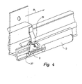
Fig. 4 the device, as the rail 1 of the drawer is being moved into the furniture body as indicated by arrow B; everything is shown in perspective. - The device shown in
Fig. 1 is intended for the mounting of a drawer in a furniture body. Neither the drawer nor the furniture body is shown. However, the drawer is mounted right on top of the top side of a rail 1. The drawer may, when it is opened, be moved to the left as shown by arrow A inFig. 2 . The rail 1 is attached to and may be displaced in relation to alower rail 3 that is attached to a vertical wall in the not-shown drawer hole in the not-shown furniture body. -
Fig. 1 and2 show how the device at the left end of the rail 3 - and thus attached to the furniture body - is furnished with adamper 6 containing a fluid medium with some degree of viscosity, for example gas, oil or water. However, the medium may also be air. In the damper 6 a not-shown piston is mounted, which is connected to apiston rod 7 as shown inFig. 2 . The not-shown piston can perform a back-and-forward movement within thedamper 6. The outer free end of thepiston rod 7 is connected with arocker 9. Whenever the piston rod is moved in and out within thedamper 6 as part of the movement of the piston rod (corresponding to the opening and closing movement of the drawer), therocker 9 will be able to turn, namely when therocker 9 is relatively close to thedamper 6.Fig. 2 shows therocker 9 in a first end position close to thedamper 6. By means of a first pin 19 (mounted at the end of the rail 1) therocker 9 can be turned from the position shown inFig. 2 to the position shown inFig. 3 . It should be noted that thefirst pin 19 and herewith the pull-out rail 1 and the corresponding drawer cannot keep on moving further to the left due to alimit stop 10 and the fact that thepiston rod 7 is limited in size. It should also be noted that when thepin 19 is in the position shown inFig. 2 , it will - together with the thereto belonging rail 1 and drawer - be able to move diagonally upwards to the right in order to allow for the ending of the closing movement of the drawer as therocker 9 in the shown position has turned free from thepin 19. - As shown in
Fig. 2 and3 , around the piston rod 7 - on the part of thepiston rod 7 that lies between thedamper 6 and the rocker 9 - there may be mounted acoil spring 11, which can secure a not too fast pulling out of the drawer, i.e. a not too fast movement of the drawer to the left, at the final stage of the opening of the drawer (the pulling out). It should be noted that when thepin 19 of a drawer during closing has been moved into the position shown inFig. 4 , i.e. the drawer has been moved in the direction of arrow B, thepin 19 will go clear the device according to the invention, after which the drawer will be able to be pushed into its closing position in an ordinary way. The closing of the drawer is done by the user. Thecoil spring 11 might be mounted within thedamper 6. In this case the coil spring may be arranged between the not-shown piston of the damper and thedamper bottom piece 34 facing away from the piston rod. -
Fig. 2 shows how therocker 9 may have a supporting element, which is placed across the principal plane of the rocker - here in the form of twomain pins 12, 13. However, the second of the two main pins is indicated by a dotted line only, since it is situated behind therocker 9. The distance X between themain pins 12, 13 is preferably larger than 1.2 - for example 1.3 - times the width of thepin 19. Therocker 9 has also two auxiliary pins 12a, 13a, which can slide through agroove 18 in theguide portion 17. As shown inFig. 2 andFig. 4 , the second auxiliary pin 13a may have slid down into the curved groove portion 18a in theguide portion 17. However, if therocker 9 is turned, the auxiliary tap 13a can be moved upwards and rest on awall 18b in a horizontal groove orslot 18 in theguide portion 17. Also the first auxiliary pin 12a can slide in thisgroove 18. It should be noted that simultaneously with the auxiliary pin 13a being moved downwards in the curved groove portion 18a, the main pin 13 will finally slide down into a depression 35 in theguide portion 17. - The
damper 6, theguide portion 17 and therocker 9 may for example be made of plastic, preferably Acetal® or polyamide. - The
coil spring 11 referred to is preferably a pressure spring. - As shown in
Fig. 2 therocker 9 may be connected to the outer end of thepiston rod 7 by means of a supportingelement 33, which slides in aslot 32 in theguide portion 17. As appears fromFig. 4 , the supportingelement 33 may have a thickenedpart 37, which can secure the supportingelement 33 in theslot 32. As shown, the supportingelement 33 may have a mainly V-shaped cross section. - As shown in
Fig. 1 there might be mounted adevice 25, possibly rather deep inside the furniture body, namely on therail 3. This device automatically secures a soft ending of the closing movement of the drawer in the not-shown furniture body. Furthermore, there may be mounted asecond pin 27 on the pull-out rail 1, which, whenever the drawer is pushed inwards closing the drawer, can engage with a second tilt-able rocker 29 mounted on a second piston rod in asecond damper 31. Thissecond pin 27 is arranged so as to function in a plane parallel to the plane in which the first pin functions. The plane in which thesecond pin 27 functions is situated a bit further away from the reader's point of view than the plane in which thefirst pin 19 functions. - Close to the second piston rod, preferably parallel hereto, there may be mounted a second coil spring, which - in the same way as the first coil spring pushes the
first piston rod 7 outwards - can push the second piston rod outwards. Also thesecond damper 31 can through a fluid medium push the second piston rod outwards. - The invention may be modified in many ways without deviating from the general idea of the invention.
-
- 1. Device for securing a soft ending of the opening movement of a drawer as the latter is drawn towards an outer limit stop, the drawer being mounted in a furniture body and capable of being pulled out from said body, and in which there may be one or more rails (1, 3) between the drawer and the furniture body, characterised in that it comprises a damper (6) filled with a fluid medium, such as air, gas, oil, water or other types of liquids, attached to the furniture body - or to a rail of the furniture body - and a piston with a piston rod (7) being reciprocable in said damper (6), the free end of the piston rod (7) being attached to a tilt-able rocker (9), and where the rocker, whenever the piston rod (7) is moved in and out in the damper (6), can be moved on a guide portion (17) - mounted at the damper - between a first end position (
Fig. 2 ) close to the damper, in which a first pin (19) mounted at the back of the drawer may engage with the rocker (9), and a second end position (Fig. 3 ) far from the damper (6), in which the piston rod (7) is in its outermost position. - 2. Device according to embodiment 1, characterised in that a coil spring (11) is mounted around the piston rod (7) on the part that lies between the damper (6) and the rocker (9).
- 3. Device according to embodiment 1, characterised in that the coil spring is mounted within the damper (6) between the piston and the bottom piece (34) in the damper.
- 4. Device according to
embodiment 1, 2 or 3, characterised in that the rocker (9) has at least one supporting element, which is placed across the principal plane of the rocker (9) and which preferably is constituted of at least one main pin (12, 13). - 5. Device according to one or more of the embodiments 1-4, characterised in that the rocker (9) has two main pins (12, 13) placed at a distance from each other of preferably more than 1.2 - possibly more than 1.3 - times the width of said first pin (19).
- 6. Device according to one or more of the embodiments 1-5, characterised in that one or two auxiliary pins (12a, 13a) are arranged at a level under the main pin (12, 13) of the rocker (9), said auxiliary pin or pins being adapted so as to slide through a longitudinal - possibly open-worked - groove (18) in the guide portion (17), said groove (18) at one end having a curved groove portion (18a) in order to provide a turning of the rocker (9), when at least one of the auxiliary pins (13a) of the rocker has reached the curved groove portion (18a).
- 7. Device according to one or more of the embodiments 1-6, characterised in that there is a horizontal supporting surface (18c) for the main pin(s) (12, 13) on the top side of the guide portion (17), said supporting surface having a depression (35) on the spot closest to the damper (6), and in which a main pin (12, 13) can slide in, when the drawer is closed.
- 8. Device according to one or more of the embodiments 1-7, characterised in that the two auxiliary pins (12a, 13a) of the rocker (9) are placed at such a distance from each other that only one of the auxiliary pins (13a,
Fig. 2 ) can slide into the curved groove portion (18a). - 9. Device according to one or more of the embodiments 1-8, characterised in that the rocker (9) is connected to the outer end of the piston rod by means of a supporting element (33), which preferably is guided in a slot (32) in the guide portion (17), the supporting element (33) for example being equipped with a thickened part (37), which can keep the supporting element in place in the slot (32).
- 10. Device according to one or more of the embodiments 1-9, characterised in that the damper (6), the guide portion (17) and the rocker (9) are made of plastic, preferably Acetal® or polyamide.
- 11. Device according to one or more of the embodiments 1-10, characterised in that the coil spring (11) is a pressure spring.
- 12. Device according to one or more of the embodiments 1-11, characterised in that at the connection of the drawer and the furniture body there is mounted a device (25) for automatically securing a soft ending of the closing movement of the drawer in the furniture body, a second pin (27) mounted on the drawer - or on its rail - during the inward movement of the drawer being capable of engaging a second tilt-able rocker (29) that is mounted at the end of a second piston rod in a second damper (31), said second pin (27) being arranged so as to function in a plane parallel to the plane in which the first pin is functioning.
- 13. Device according to
embodiment 12, characterised in that there is mounted a second coil spring, preferably a tension spring, near the second piston rod, preferably parallel hereto. - 14. Device mainly as described above with reference to the drawings.
Claims (13)
- A soft ending of opening movement device, comprising:- a guide portion (17) comprising a longitudinal groove (18) and a slot (32),- a damper (6) filled with fluid medium,- a piston with a piston rod (7) being reciprocable in said damper (6),- a tilt-able rocker (9) that is moveable on the guide portion (17) between a first end position where the tilt-able rocker (9) is adapted to engage a first pin (19) and a second end position adapted to preventing the pin (19) to move further, characterised in that the device further comprises a supporting element (33) connected to an outer end of the piston rod (7), where the support element slides in the slot (32) of the guide portion (17), and where tilt-able rocker (9) is connected to the outer end of the piston rod (7) via said support element (32).
- A soft ending of opening movement device according to claim 1, wherein the first end position of the tilt-able rocker (9) is close to the damper (6), and the second end position of the tilt-able rocker (9) is far from the damper (6), in which the piston rod (7) is in its outermost position.
- A soft ending of opening movement device according to any of the preceding claims, characterised in that a coil spring (11) is mounted around the piston rod (7) on the part that lies between the damper (6) and the rocker (9).
- A soft ending of opening movement device according to claim 3, characterised in that the coil spring is mounted within the damper (6) between the piston and a bottom piece (34) in the damper.
- A soft ending of opening movement device according to any of the preceding claims, characterised in that the rocker (9) has at least one supporting element, which is placed across the principal plane of the rocker (9) and which preferably is constituted of at least one main pin (12, 13).
- A soft ending of opening movement device according to any of the preceding claims, characterised in that the rocker (9) has two main pins ( 12, 13) placed at a distance from each other of preferably more than 1.2- possibly more than 1.3- times the width of said first pin (19).
- A soft ending of opening movement device according to any of the preceding claims, characterised in that one or two auxiliary pins (12a, 13a) are arranged at a level under the main pin (12, 13) of the rocker (9), said auxiliary pin or pins being adapted so as to slide through the longitudinal groove (18) in the guide portion (17), said groove (18) at one end having a curved groove portion (18a) in order to provide a turning of the rocker (9), when at least one of the auxiliary pins (13a) of the rocker has reached the curved groove portion ( 18a ).
- A soft ending of opening movement device according to one or more of the claims to any of the preceding claims, characterised in that there is a horizontal supporting surface (18c) for the main pin(s) (12, 13) on the top side of the guide portion (17), said supporting surface having a depression (35) on the spot closest to the damper (6), and in which a main pin (12, 13) can slide in during closing movement.
- A soft ending of opening movement device according to any of the preceding claims, characterised in that the two auxiliary pins (12a, 13a) of the rocker (9) are placed at such a distance from each other that only one of the auxiliary pins (13a) can slide into the curved groove portion (18a).
- A soft ending of opening movement device according to any of the preceding claims, characterised in that the rocker (9) is connected to the outer end of the piston rod by means of a supporting element {33), which preferably is guided in a slot {32) in the guide portion {17), the supporting element (33) for example being equipped with a thickened part (37), which can keep the supporting element in place in the slot (32).
- A soft ending of opening movement device according to any of the preceding claims, characterised in that the damper (6), the guide portion ( 17) and the rocker (9) are made of plastic, preferably Acetal® or polyamide.
- A soft ending of opening movement device according to any of the preceding claims, characterised in that the coil spring (11) is a pressure spring.
- A rail system for the soft ending of an opening movement, comprising- a first rail (1) comprising a first pin (19), and- a second rail (3) furnished with a device according to any of claims 1-12- where the first rail (1) is attached to and may be displaced in relation to the second rail (2), so that the first pin (19) can engage the tilt-able rocker (9) in its first end position and move to the second end position for softening the opening movement of the rail system.
Applications Claiming Priority (2)
| Application Number | Priority Date | Filing Date | Title |
|---|---|---|---|
| DK200700695A DK200700695A (en) | 2007-05-09 | 2007-05-09 | Device for securing a smooth finish of the opening movement of a drawer |
| EP08750894.1A EP2150151B1 (en) | 2007-05-09 | 2008-05-08 | Method for securing a soft ending of the opening movement of a drawer |
Related Parent Applications (1)
| Application Number | Title | Priority Date | Filing Date |
|---|---|---|---|
| EP08750894.1 Division | 2008-05-08 |
Publications (1)
| Publication Number | Publication Date |
|---|---|
| EP2522254A1 true EP2522254A1 (en) | 2012-11-14 |
Family
ID=39620347
Family Applications (2)
| Application Number | Title | Priority Date | Filing Date |
|---|---|---|---|
| EP12179999A Ceased EP2522254A1 (en) | 2007-05-09 | 2008-05-08 | A soft ending of opening movement device |
| EP08750894.1A Not-in-force EP2150151B1 (en) | 2007-05-09 | 2008-05-08 | Method for securing a soft ending of the opening movement of a drawer |
Family Applications After (1)
| Application Number | Title | Priority Date | Filing Date |
|---|---|---|---|
| EP08750894.1A Not-in-force EP2150151B1 (en) | 2007-05-09 | 2008-05-08 | Method for securing a soft ending of the opening movement of a drawer |
Country Status (11)
| Country | Link |
|---|---|
| US (1) | US8827388B2 (en) |
| EP (2) | EP2522254A1 (en) |
| CN (1) | CN101801240B (en) |
| CY (1) | CY1114633T1 (en) |
| DK (2) | DK200700695A (en) |
| ES (1) | ES2431340T3 (en) |
| HR (1) | HRP20130956T1 (en) |
| PL (1) | PL2150151T3 (en) |
| PT (1) | PT2150151E (en) |
| SI (1) | SI2150151T1 (en) |
| WO (1) | WO2008139298A1 (en) |
Cited By (1)
| Publication number | Priority date | Publication date | Assignee | Title |
|---|---|---|---|---|
| DE102012111551B4 (en) | 2011-11-28 | 2023-08-31 | Paul Hettich Gmbh & Co. Kg | drawer guide |
Families Citing this family (17)
| Publication number | Priority date | Publication date | Assignee | Title |
|---|---|---|---|---|
| DE202009002715U1 (en) * | 2009-02-25 | 2010-07-15 | Paul Hettich Gmbh & Co. Kg | Pull-out guide for a furniture pull-out part |
| MY151706A (en) * | 2009-08-12 | 2014-06-30 | Harn Marketing Sdn Bhd | Drawer assembly |
| DE102011012288B4 (en) * | 2011-02-24 | 2012-10-31 | Gebr. Willach Gmbh | sliding door |
| DE102011051138A1 (en) | 2011-06-17 | 2012-12-20 | Schock Metallwerk Gmbh | pull-out guide |
| DE102011052524A1 (en) * | 2011-08-09 | 2013-02-14 | Schock Metallwerk Gmbh | pull-out guide |
| DE102011122266A1 (en) * | 2011-12-23 | 2013-06-27 | Grass Gmbh | Device for influencing the movement of a furniture part, guide unit for moving a furniture part and furniture |
| US8801120B2 (en) * | 2012-09-12 | 2014-08-12 | King Slide Works Co., Ltd. | Self-opening and self-closing slide assembly |
| EP2868238A1 (en) * | 2013-11-01 | 2015-05-06 | Norpe Oy | Temperature controlled display cabinet, in particular a freezer island, comprising a door |
| DE202013011559U1 (en) * | 2013-12-23 | 2015-03-24 | Grass Gmbh | damping device |
| TWM493587U (en) * | 2014-08-05 | 2015-01-11 | Weider Metal Inc | Closed position adjustment mechanism of push-pull door bumper device |
| DE202015006279U1 (en) * | 2015-09-04 | 2016-12-07 | Grass Gmbh | Damping device for damping the opening movement of a movable furniture part |
| WO2017157796A1 (en) * | 2016-03-16 | 2017-09-21 | Paul Hettich Gmbh & Co. Kg | Self-closing device and drawer runner |
| CN107198375B (en) * | 2016-03-16 | 2020-11-10 | 保罗海蒂诗有限及两合公司 | Retracting device and pull-out guide device |
| EP3825226B1 (en) | 2016-11-28 | 2022-10-26 | AIRBUS HELICOPTERS DEUTSCHLAND GmbH | A rotary wing aircraft with a sliding element, in particular a sliding door or a sliding window |
| US10433702B2 (en) | 2017-07-18 | 2019-10-08 | Haier Us Appliance Solutions, Inc. | Damped closure assembly for a dishwasher appliance |
| US11667512B2 (en) * | 2021-03-26 | 2023-06-06 | Henkel Ag & Co. Kgaa | Dispensing system for dispensing a liquid from a replacement container |
| CN113953104A (en) * | 2021-11-27 | 2022-01-21 | 广州恩维汽车配件有限公司 | Speed-reducing telescopic nozzle |
Citations (4)
| Publication number | Priority date | Publication date | Assignee | Title |
|---|---|---|---|---|
| DE20315124U1 (en) * | 2003-09-29 | 2004-02-26 | Hettich-Heinze Gmbh & Co. Kg | Sliding support system and movement damping system for movable part of piece of furniture has tongue on bracket engaging jaws connected to spring and damper unit in fixed part |
| US20040107536A1 (en) * | 2002-12-06 | 2004-06-10 | Helmut Hollenstein | Closure device for movable furniture parts |
| WO2006025149A1 (en) * | 2004-08-30 | 2006-03-09 | Shimodaira Hardware Co., Ltd. | Door closing device for sliding door |
| WO2006050510A2 (en) * | 2004-11-05 | 2006-05-11 | Accuride International, Inc. | Dampened movement mechanism and slide incorporating the same |
Family Cites Families (10)
| Publication number | Priority date | Publication date | Assignee | Title |
|---|---|---|---|---|
| DE19935120C2 (en) * | 1999-07-27 | 2001-05-17 | Bulthaup Gmbh & Co | Device for opening and closing a drawer |
| DE20210295U1 (en) * | 2002-07-03 | 2002-09-05 | Arturo Salice S.P.A., Novedrate, Como | Device for damping impacts, preferably the impacts of furniture doors or drawers |
| AT6364U1 (en) * | 2002-08-29 | 2003-09-25 | Blum Gmbh Julius | EXTENSION GUIDE SET FOR DRAWERS |
| ATE335427T1 (en) * | 2003-05-05 | 2006-09-15 | Blum Gmbh Julius | EXTENSION SET FOR DRAWERS |
| ATE526850T1 (en) * | 2003-05-13 | 2011-10-15 | Grass Gmbh | FRONTAL LOCKING DEVICE FOR REleasably engaging a drawer in a drawer slide |
| ITMC20030144A1 (en) | 2003-12-05 | 2005-06-06 | Compagnucci Spa Ora Compagnucci Ho Lding Spa | DEVICE FOR AUTOMATIC AND SUSPENSION CLOSING OF DRAWERS AND REMOVABLE FACILITIES FOR FURNITURE. |
| JP4446825B2 (en) * | 2004-07-21 | 2010-04-07 | 株式会社ニフコ | Slide assist device |
| JP4446824B2 (en) * | 2004-07-21 | 2010-04-07 | 株式会社ニフコ | Slide assist device |
| DE102006019351B4 (en) | 2006-04-24 | 2008-08-28 | Zimmer, Günther | Guidance system with acceleration and deceleration device |
| TWI321995B (en) * | 2007-05-15 | 2010-03-21 | King Slide Works Co Ltd | Drawer slide assembly with an undermount drawer slide |
-
2007
- 2007-05-09 DK DK200700695A patent/DK200700695A/en not_active Application Discontinuation
-
2008
- 2008-05-08 US US12/451,372 patent/US8827388B2/en not_active Expired - Fee Related
- 2008-05-08 EP EP12179999A patent/EP2522254A1/en not_active Ceased
- 2008-05-08 ES ES08750894T patent/ES2431340T3/en active Active
- 2008-05-08 EP EP08750894.1A patent/EP2150151B1/en not_active Not-in-force
- 2008-05-08 SI SI200831104T patent/SI2150151T1/en unknown
- 2008-05-08 CN CN2008800214501A patent/CN101801240B/en not_active Expired - Fee Related
- 2008-05-08 PL PL08750894T patent/PL2150151T3/en unknown
- 2008-05-08 PT PT87508941T patent/PT2150151E/en unknown
- 2008-05-08 HR HRP20130956AT patent/HRP20130956T1/en unknown
- 2008-05-08 WO PCT/IB2008/001138 patent/WO2008139298A1/en not_active Ceased
- 2008-05-08 DK DK08750894.1T patent/DK2150151T3/en active
-
2013
- 2013-10-10 CY CY20131100891T patent/CY1114633T1/en unknown
Patent Citations (4)
| Publication number | Priority date | Publication date | Assignee | Title |
|---|---|---|---|---|
| US20040107536A1 (en) * | 2002-12-06 | 2004-06-10 | Helmut Hollenstein | Closure device for movable furniture parts |
| DE20315124U1 (en) * | 2003-09-29 | 2004-02-26 | Hettich-Heinze Gmbh & Co. Kg | Sliding support system and movement damping system for movable part of piece of furniture has tongue on bracket engaging jaws connected to spring and damper unit in fixed part |
| WO2006025149A1 (en) * | 2004-08-30 | 2006-03-09 | Shimodaira Hardware Co., Ltd. | Door closing device for sliding door |
| WO2006050510A2 (en) * | 2004-11-05 | 2006-05-11 | Accuride International, Inc. | Dampened movement mechanism and slide incorporating the same |
Cited By (1)
| Publication number | Priority date | Publication date | Assignee | Title |
|---|---|---|---|---|
| DE102012111551B4 (en) | 2011-11-28 | 2023-08-31 | Paul Hettich Gmbh & Co. Kg | drawer guide |
Also Published As
| Publication number | Publication date |
|---|---|
| CY1114633T1 (en) | 2016-10-05 |
| SI2150151T1 (en) | 2014-01-31 |
| CN101801240B (en) | 2013-01-09 |
| CN101801240A (en) | 2010-08-11 |
| EP2150151A1 (en) | 2010-02-10 |
| PL2150151T3 (en) | 2014-01-31 |
| HRP20130956T1 (en) | 2013-11-08 |
| EP2150151B1 (en) | 2013-09-04 |
| WO2008139298A1 (en) | 2008-11-20 |
| DK200700695A (en) | 2008-11-10 |
| US20100293746A1 (en) | 2010-11-25 |
| PT2150151E (en) | 2013-09-24 |
| ES2431340T3 (en) | 2013-11-26 |
| HK1145067A1 (en) | 2011-04-01 |
| DK2150151T3 (en) | 2013-12-16 |
| US8827388B2 (en) | 2014-09-09 |
| WO2008139298A8 (en) | 2010-06-03 |
Similar Documents
| Publication | Publication Date | Title |
|---|---|---|
| EP2522254A1 (en) | A soft ending of opening movement device | |
| JP3125539U (en) | Automatic closing device with drawer slide rail | |
| JP4415221B2 (en) | Closing device and / or retracting device for movable furniture parts | |
| KR101391247B1 (en) | Automatically closing apparatus | |
| US9364089B1 (en) | Self-closing slide rail assembly with deceleration mechanism | |
| KR20170015333A (en) | Sliding-pivoting mechanism of a shelf of a piece of furniture or of a domestic appliance, piece of furniture, and a domestic appliance | |
| JP2001087065A (en) | Telescopic rail | |
| JP2012505326A (en) | Self-opening and closing device used for movable furniture members | |
| EP2374370A1 (en) | Attachment device for attaching a panel to a furnishing element | |
| CN102112023B (en) | Furniture pull-out guide | |
| CN101384193A (en) | Automatic moving mechanism and sliding device comprising same | |
| US10028583B2 (en) | Closing device, extension runner having a closing device as well as furniture item having an extension runner | |
| EP3403530B1 (en) | Driving mechanism, protection device and control method applicable to furniture | |
| US11464331B2 (en) | Pull-out guide | |
| KR101893132B1 (en) | A refrigerator in use with auto drawer | |
| CA3093506C (en) | Pull-out guide | |
| HK1145067B (en) | Device for securing a soft ending of the opening movement of a drawer | |
| CN114431646B (en) | Pull out the guide | |
| TW200936865A (en) | Pull-in mechanism | |
| KR101056922B1 (en) | Durable automatic closing device | |
| KR101056874B1 (en) | Automatic closing device with damper | |
| KR200398982Y1 (en) | Refrigerator slide with a self closing member | |
| EP3155930A1 (en) | Dampened opening guide for sliding parts of furniture, such as drawers or the like | |
| KR101056919B1 (en) | Automatic closing device for bottom mounting slide | |
| KR200393608Y1 (en) | Auto control device of slide a rail |
Legal Events
| Date | Code | Title | Description |
|---|---|---|---|
| PUAI | Public reference made under article 153(3) epc to a published international application that has entered the european phase |
Free format text: ORIGINAL CODE: 0009012 |
|
| AC | Divisional application: reference to earlier application |
Ref document number: 2150151 Country of ref document: EP Kind code of ref document: P |
|
| AK | Designated contracting states |
Kind code of ref document: A1 Designated state(s): AT BE BG CH CY CZ DE DK EE ES FI FR GB GR HR HU IE IS IT LI LT LU LV MC MT NL NO PL PT RO SE SI SK TR |
|
| 17P | Request for examination filed |
Effective date: 20130514 |
|
| 17Q | First examination report despatched |
Effective date: 20130712 |
|
| STAA | Information on the status of an ep patent application or granted ep patent |
Free format text: STATUS: THE APPLICATION HAS BEEN REFUSED |
|
| 18R | Application refused |
Effective date: 20160403 |