EP2522018B1 - Verfahren für aufpralleinwirkung in einem vakuum - Google Patents
Verfahren für aufpralleinwirkung in einem vakuum Download PDFInfo
- Publication number
- EP2522018B1 EP2522018B1 EP11703236.7A EP11703236A EP2522018B1 EP 2522018 B1 EP2522018 B1 EP 2522018B1 EP 11703236 A EP11703236 A EP 11703236A EP 2522018 B1 EP2522018 B1 EP 2522018B1
- Authority
- EP
- European Patent Office
- Prior art keywords
- accelerator
- pellets
- target
- pellet
- vacuum
- Prior art date
- Legal status (The legal status is an assumption and is not a legal conclusion. Google has not performed a legal analysis and makes no representation as to the accuracy of the status listed.)
- Not-in-force
Links
Images

Classifications
-
- G—PHYSICS
- G21—NUCLEAR PHYSICS; NUCLEAR ENGINEERING
- G21B—FUSION REACTORS
- G21B1/00—Thermonuclear fusion reactors
- G21B1/11—Details
- G21B1/15—Particle injectors for producing thermonuclear fusion reactions, e.g. pellet injectors
-
- G—PHYSICS
- G21—NUCLEAR PHYSICS; NUCLEAR ENGINEERING
- G21B—FUSION REACTORS
- G21B1/00—Thermonuclear fusion reactors
- G21B1/11—Details
- G21B1/19—Targets for producing thermonuclear fusion reactions, e.g. pellets for irradiation by laser or charged particle beams
-
- G—PHYSICS
- G21—NUCLEAR PHYSICS; NUCLEAR ENGINEERING
- G21B—FUSION REACTORS
- G21B3/00—Low temperature nuclear fusion reactors, e.g. alleged cold fusion reactors
- G21B3/006—Fusion by impact, e.g. cluster/beam interaction, ion beam collisions, impact on a target
-
- Y—GENERAL TAGGING OF NEW TECHNOLOGICAL DEVELOPMENTS; GENERAL TAGGING OF CROSS-SECTIONAL TECHNOLOGIES SPANNING OVER SEVERAL SECTIONS OF THE IPC; TECHNICAL SUBJECTS COVERED BY FORMER USPC CROSS-REFERENCE ART COLLECTIONS [XRACs] AND DIGESTS
- Y02—TECHNOLOGIES OR APPLICATIONS FOR MITIGATION OR ADAPTATION AGAINST CLIMATE CHANGE
- Y02E—REDUCTION OF GREENHOUSE GAS [GHG] EMISSIONS, RELATED TO ENERGY GENERATION, TRANSMISSION OR DISTRIBUTION
- Y02E30/00—Energy generation of nuclear origin
- Y02E30/10—Nuclear fusion reactors
Definitions
- a fusion reactor for use in space can have design parameters that would be impracticable on Earth. If an extremely long vacuum gap is available, there is time for a stream of microparticles fired from a linear accelerator of relatively modest power to catch up into a cluster if given a small speed differential, with the first particles launched travelling the slowest and the last the most rapidly: the accelerator power needed scales inversely as the size of vacuum gap.
- the particles must be steered by applying small course corrections en route.
- a first correction as they leave the accelerator is relatively straightforward. However much more accurate corrections must be made on arrival at the lunar surface. This is why a grazing angle is chosen: taking advantage of lunar topography, and siting both the first incoming course correction station and the reactor on 2 km high lunar mountaintops, a distance between the first incoming course correction station and the reaction site of about 100 miles is achievable.
- the accelerator design is very similar to that of a linear accelerator for fundamental particles, but operating at a lower frequency as the particle speed is ⁇ 1/300 that of light.
- the inter-electrode gaps therefore do not act as RF resonant cavities, and a dielectric (non-conducting) wall design can be chosen. Breakdown is more prone to occur over the surface of an insulator than within the interior.
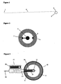
- An internal accelerator cross section like that in Figure 2 may therefore be optimal, in which each conducting electrode 5 is mounted within an insulating tube 6 of substantially larger internal diameter.
- the surface path length between the wires 7 and 8 to which alternate electrodes are connected can be several times larger than the inter-electrode gap.
- An appropriate material for the insulator is Teflon or Rexolite, and for the electrodes copper, molybdenum or tungsten polished to maximize their surface field breakdown strength. Accelerator length will be of the order of a few kilometres.
- particles will transit the accelerator spaced 2 n electrode intervals behind one another if it is a 2-phase accelerator, 3n electrode intervals behind one another if it is a 3-phase acclerator, etc., where n is an integer, typically 1. (However the accelerator might operate with a group of particles, rather than a single one, at each such position.) Typically, particles will emerge with relative speeds proportional to the longitudinal interval between them, so that all particles ultimately meet at the same instant.
- Appropriate material for the particles will have high tensile strength and low density for maximum charge/mass ratio. It should be stiff so that it does not overheat due to flexure, as the electric field and therefore acceleration experienced cycles at the drive frequency of the accelerator, and either an insulator of high breakdown strength or a reasonably good conductor, so that the charge flow induced on its surface does not damage it.
- Plausible candidates include diamond, boron- ⁇ , aluminium-lithium alloy, or even microspheres of an engineering plastic such as celazole with a thin surface coating of metal such as aluminium.
- the latter requires a longer accelerator, but has the advantage that if (in place of a conventional target of DT ice) a target of solid methane in which the hydrogen has been replace by deuterium and tritium is used, the average atomic weight of pellets and target can be made very similar, suppressing Rayleigh-Taylor instabilities.
- the particles should preferably be given a positive rather than negative charge, as field effect electron emission becomes significant at a much lower voltage gradient than field effect evaporation. Whatever material is chosen, the smaller the particles, the higher charge/mass ratio they can tolerate: however obviously more particles are then required for a given total kinetic energy. Suitable particle size is likely to be on the general order of ⁇ 10 microns radius, with between 10000 and 1 million particles used.
- Accelerator optimal frequency will be much lower than that of a fundamental particle accelerator, ⁇ MHz rather than GHz.
- Commercially available options to provide this power supply include diacrodes, tetrodes, or MOSFET-based units in conjunction with air-core transformers to boost their output voltage.
- the particles should be guided as precisely as possible into a close-packed array, for example resembling a crystal lattice.
- Ideal precision required is a small fraction of the particle size, preferably ⁇ 1 micron or better. While this is demanding, it can be attained with consecutively fmer corrections analogous to a spacecraft's mid-course corrections.
- the limiting factor is precision of position measurement. This can be done by CCD camera pairs with microscope-style lenses sited by the beamline. Exposure is controlled by laser pulse: laboratory desktop lasers with pulse ⁇ 1 picosecond, corresponding to particle movement 1 micron, are available.
- CCD chips can do useful onboard processing, but readout rates are limited to a few tens of megabytes/sec, so many cameras will typically be needed at each measurement station.
- the number of lasers needed is far smaller: a laser feeding a leaky optical fibre running parallel to the beamline can serve many cameras.
- Particle steering is done by the particles passing close to or between rapidly switched electrodes, which can steer them laterally in any direction and/or slightly alter their speed.
- Solid state power switches operating at tens of GHz are now available, so a relatively small number of electrodes can perform course corrections on thousands or even millions of particles as they pass.
- An alternative to electric fields provided by electrodes is electromagnetic fields generated by rapidly switching current through short antenna-like wires.
- the particles require to be maximally charged for acceleration. Subsequently, mutual repulsion as they draw closer to one another is preferably minimised.
- the particles require only modest charge to be steered by successively smaller course corrections, so they can be progressively discharged, e.g. by passing through an electron beam or close to a hot or cold cathode after each course correction point, ultimately to zero.
- the most easily achievable fusion reaction is deuterium-tritium. Because tritium does not occur naturally, it is desirable that as far as possible, all neutrons produced should be captured by lithium nuclei to bred more tritium. It is also desirable to minimize wear on the reaction chamber walls.
- A. suitable arrangement is shown in Figure 3 (necessarily not drawn not to scale: actual-pellet number will typically be thousands, each ⁇ 20 ⁇ m diameter).
- a sacrificial projectile (9) is fired into a reaction chamber (10) whose walls are protected by a 'waterfall' (11) of lithium or a lithium compound.
- the target (12) is, at the moment of impact, within the sacrificial projectile which has entered the reaction chamber in a direction substantially parallel to the particles (13).
- the projectile has a hole (14) which permits passage of the pellets to strike the target.
- the projectile can itself be wholly or partly made of lithium.
- the vacuum pipe (16) from which the pellets emerge and a projectile loading barrel (17) containing the next projectile (18). For continuous power generation, several projectiles are fired in per second.
- the melt from the reaction chamber is circulated through a heat exchanger (e.g. by electromagnetic pump) to extract its thermal energy: the projectile material is extracted for recycling, as new projectiles must continuously be made. Tritium is also extracted.
- a heat exchanger e.g. by electromagnetic pump
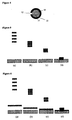
- the 'virtual bullet' formed by the coalescing particles will be less dense than a normal solid of the same material, e.g. if the particles are perfect uniform spheres then at least by the ratio of the spherical packing fraction ⁇ 0.74, and less than that if allowance is made for inevitable inaccuracies in their shape, position and size.
- the bullet will compress to many times the normal density of the raw material as (or just before or after) it strikes the target.
- FIG. 5 shows a basic configuration: particles come together to form a precompressed bullet before striking the target.
- Figure 6 shows a variant in which additional particles, fired first at lower speed, pre-compress the target before the bullet strikes it.
- Figure 7 shows a variant in which there is no pre-positioned target: rather additional particles, fired earlier at lower speeds, actually constitute the target.
- Figure 8 shows a variant in which the prepositioned target is not flat but conical, so that it is precompressed sideways as well as vertically before the bullet strikes it.
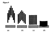
- Figure 9 shows a bullet whose central part travels fastest, so first ignition occurs at the centre.
- the particles may be of differing sizes, shapes and made of different materials
- the target if a prepositioned target is provided
- the ensemble may provide back and front portions of dense material constituting a 'hammer' and 'anvil', between which the material to be fused is sandwiched.
- the particles can comprise outer shells of one material containing a second material within, e.g. the second material might be helium-3.
- the particles may have their charge neutralised (e.g. by spraying electrons on to them) so that they do not repel one another as they come together. Electron sprays might combine the functions of charge neutralisation, electron microscopy for precise position measurement, and adjustment of particle trajectory by momentum exchange. In a terrestrial system, particles may equally conveniently be measured and adjusted at any point in flight, not just near the accelerator or target ends of the system.
- Obvious applications include power generation, spaceship propulsion, asteroid propulsion.
- the Tetris method may be suitable for separating compression and ignition, which is difficult to do by either laser or with a single physical bullet, for two reasons:
- a Tetris accelerator can, at no extra cost, fire many slower pellets immediately preceding the higher energy ignition pulse, with all arriving near-simultaneously.
- the extra pellets can supply energy and/or momentum for target precompression.
- the ignition bullet is made by a train of pellets of differing speed coming together, it can easily be both precompressed to high density, and given a very high mass per frontal area, like an armour-piercing bullet. Thus it can punch through and deposit most of its energy at the heart of even a dense target plasma.
- the accelerator operates on the same principle as a fundamental particle accelerator. However because the pellets travel at less than 1% of light speed, the drive frequency can be much lower. Tiny cheap MOSFET transistors thus can be used in place of klystrons for power conditioning, with small air-core (or vacuum-core) transformers to boost their output voltage.
- the electrodes do not form RF resonant cavities, and can be simple disks of metal mounted within a Teflon tube. Three-phase electrodes can be used (or even more phases) so that individual pellets ride a 'wave' of near-constant electric field. This minimizes vibration and induced surface current, so the pellets can be made from any reasonably strong material, e.g. plastic microspheres.
- pellets could be injected from a 'waterfall' which falls between a pair of electrode plates. Individual pellets are 'zapped' with electrons from a steerable cathode ray tube beam (or positive ions from an ion gun) to adjust their time and speed of entry into the accelerator.
- the ideal fusion reactor requires no rare or radioactive isotopes as input, and produces no radioactive isotopes as output.
- Basic DT fusion as above does not achieve this goal.
- the blast chamber could in principle be surrounded with pure elements which do not produce unwanted isotopes under neutron bombardment, for continued operation it is necessary to breed tritium from lithium.
- the DT reaction itself does not yield sufficient neutrons for this, so it is normally assumed that fissionable isotopes must be included in the blast chamber surround, which intentionally multiply up the number of neutrons available to react with the lithium.
- a Tetris reactor can easily be scaled up to much higher energies.
- the reaction cross-section becomes large enough to support DD direct burn, with the reactions DD -> Helium-3 + n and DD -> tritium + p taking place at approximately equal rates. So by raising the reaction temperature and including a higher proportion of D to T, the Tetris reactor can manufacture sufficient tritium for its own use. (helium-3 is not radioactive.) More ambitiously, the reaction Boron-11 + p -> Helium-4 might be achievable.
- a pair of opposed-Tetris accelerators firing boron pellets into a central hydrogen target may well be optimal. Boron- ⁇ pellets are strong and can be given a high charge-mass ratio. All mass used is actually involved in the fusion, and the centre of mass is stationary with respect to the frame of the accelerators, so hydrodynamic efficiency is close to 100%.
- the accelerators used do not necessarily have to face one another exactly, so problems with curvature of the Earth's surface are minimized.
- Tubes need only be separated by only a few times their electrode spacing to minimize mutual interference. Spare tubes can be provided. A worst-case pellet disintegration damages only one tube; the system can continue functioning while it is replaced.
- the accelerators can be aimed so that the beams gradually converge, initially entering small individual vacuum tubes which converge to become a single tube nearer the target.
- An angled mirror can be used so that a single camera can capture a stereo image.
- the unit can measure particle position in all dimensions to ⁇ 0.1 micron. In practice a cheaper laser giving longer pulses can probably be used, with streak analysis to determine along-axis position.
- the cameras can also assess the size of each particle (shape, spin, mass and mass/charge ratio can also be measured independently if desired, e.g. by measuring the charge and also the magnitude of deflection by a known magnetic field).
- the relative positions and timings of the particles can be adjusted, and their intended destinations within the final bullet interchanged if necessary, to ensure that the density of the final bullet is almost perfectly uniform despite variations in individual particle size etc. This is analogous to the computer game Tetris.
- a possible advanced fusion target is hydrogen-boron, which produces no neutrons, hence no radionucleides.
- This reaction has resonance peaks. Given the fine-tuning possible for the virtual bullet, which can be precompressed, shape-tailored, and given any desired internal velocity distribution, the peaks may be usable.
- the pellets are assumed to be boron, an ideal material which is strong and very hard even as a pure element: compounds such as boron carbide are even tougher.
- the target may be boranes, boron-hydrogen compounds which are stable at low temperature.
- An effective fusion burn wave can be generated in a proton-boron plasma providing the plasma is degenerate, i.e. not too hot in relation to its density.
- the intrinsic ability of a Tetris accelerator to provide a first wave of slower pellets carrying high momentum relative to their energy, which arrive at the target simultaneously with the faster ignition pellets, is perfectly suited to providing such piston-like compression. Note that energy several times greater than the ignition pulse is automatically available for target precompression, by firing lower-speed pellets before the high-speed ignition burst.
- Target compression may optimally be performed by pellets travelling very much slower (orders of magnitude slower) than the ignition pellets.
- the ignition pellet accelerator would be capable of providing particles at the very slow speed appropriate, perhaps a few tens of kilometres per second, by leaving all except the first few electrodes switched off, but the impulse would be modest.
- a much larger impulse can be provided cheaply using a small ancillary accelerator which shares its expensive components - building, vacuum tube, insulation and course correction systems - with the main accelerator. Up to say 100 millisecond's worth of this machine's output can arrive at the target as a pulse: an output of just 20 MW can provide a 2 MJ compression pulse.
- the pellet arrival rate should be no greater than that of the main pulse.
- the compression particles may therefore be of order one million times as massive as the ignition particles: e.g. 100x the diameter, 50 ⁇ m.
- the ancillary accelerator will be around one-tenth the length of the main one, but a negligible fraction of its switch cost.
- the compression pellets each carry several thousand times the momentum of the ignition pellets, they also carry 100x the charge and remain within the effective vicinity of correcting fields for several hundred times as long, so the existing course tweakers can easily handle them.
- the speed ratio is so high that all compression pellets have cleared the final tweaker before the first ignition pellets arrive.
- a magnetic field is provided at a few points along the vacuum tube connecting accelerator and target to bend the compression pellet trajectories slightly upward, to prevent them falling too far under gravity.
- fast pellets may hit a front layer of material on the target which heats up and evaporates, pressing and compressing deeper layers.
- This 'rocket-like thrust' method whereby energy in the form of very fast particles heats material to cause propulsion at much lower speeds is analogous to laser-driven inertial confinement fusion, wherein the fast particles are however photons.
- Compression may be performed by pellets, and heating at a point to cause ignition provided by other means, such as laser(s) or beam(s) of fundamental particles, atoms, etc. Or vice versa.
- Fast and/or slow pellets may approach the target zone from opposite directions, or indeed from many directions. They may be fired from separate accelerators and/or have trajectories bent by passage through electric or magnetic fields. In this case there may or may not be a separate target: the pellets themselves may comprise all of the material to be fused.
- Successive fusion reactions may take place at various points within a pipe, which may be long with a narrow internal diameter.
- the rapid motion of the fusion source may help dispense the energy release (whether in the form of photons, neutrons, or other particles) along the length of the pipe so that no one portion of the pipe walls or equipment beyond is subject to damaging levels of heat, radiation, etc.
- the diacrode's major limitation is that it a fixed frequency device In the present application, about 20% launch speed variation is required. Using MOSFETs, this could be applied simply by steadily increasing the frequency during the period between the first and last pellet leaving the accelerator. With diacrodes, the solution is to switch in units at the fast end successively, resulting in sub-trains of pellets each a few metres long travelling at a uniform speed. After exiting the main accelerator, these sub-trains pass through a short run of MOSFET-controlled electrodes which are operated to speed up (or retard) pellets by differential amounts: e.g. from zero increment for the first pellet in each sub-train to a few metres per second for the last, so that each individual pellet now has a slightly different speed for perfect convergence as required.
- a longer low-power leader section is therefore provided with fixed electrode separation and highly variable drive frequency.
- This leader section is continuously fed with pellets which are precharged to a moderate voltage and fired in at (say) 5 few km/sec.
- the variable frequency electrodes accelerate this line en bloc to (say) 50 km/sec, at which point it enters the main accelerator.
- pellet voltage is raised by offsetting the local electrode voltages to the required level: note that electrons can flow easily from a pellet to the electrode it passes through, though not vice versa, as the pellet acts as a discharge point source while the electrode surface is smooth.
- pellets are released from a Pelletron-type Van de Graaff generator. This is a well known technology, except that normally pellets emerge from a source container at a chosen average rate rather than at precise intervals. Here this must be modified: a container with several orifices is used, but any pellet can be rejected just after its emergence is detected, e.g. by zapping it with an electron gun to remove its charge, or diverting it using a switched electrode.
- pellets are thus recycled, leaving just one per cycle to drop into the accelerator tube. (Note that the required rate is lower than the rate at which a modem bubblejet printer ejects ink droplets of comparable diameter.)
- the precise timing of those pellets which are allowed to fall into the accelerator can be adjusted with a smaller kick from the same electrodes used for rejection. A pair or larger group of pellets which happen to emerge from the same orifice simultancously are always rejected. There will be occasional cycles when no pellet is available, because any Poisson distribution occasionally yields a value of zero, but these gaps can be closed up by in-flight shuffling as described elsewhere. Focussing to keep the pellets centered during acceleration can be provided by electric field, e.g.
- Electrodes as cones to produce an inward radial field for part of each cycle.
- Magnetic lenses e.g. quadrupole magnets as used in a fundamental particle accelerator, and/or active steering as described elsewhere in this document, can also be used e.g. to damp down lateral oscillations.
- Pellets can be strength-tested by charging them to slightly above operational voltage before firing. In-tube pellet failure is therefore unlikely. Any failure which does occur has the potential to become contagious. However worst-case energy release is 2 MJ, and the debris cloud kinetic energy reduces exponentially at each consecutive electrode it impacts: each electrode masses more than the entire pellet cloud, and its central hole constitutes ⁇ 1% of its area. So damage will be very localised.
- the tube can be wrapped in a Kevlar blanket so that external equipment is not affected.
- Chicane traps can be incorporated at multiple points in the system: slight bends with lateral fields which divert pellets of exactly the correct charge/mass ratio into the next section, but allow other material to fly on into open ended 'dump tubes' in which the plasma from their impact is safely contained. The precise deflection of each pellet which passes successfully allows its exact charge to be monitored, and tweaked with an electron gun if necessary.
- the tube connecting accelerator and target can contain a relatively soft vacuum by particle accelerator standards: it does not need to be housed in a building, and can comprise a simple pipe mounted on pylons or stilts. It can be given a much larger internal radius, say ⁇ 10 cm, than the maximum pellet deviation from the beamline, so that it can tolerate lateral displacements due to wind etc. of several centimetres, and so that its vacuum can be maintained by pumping from a limited number of points along its length.
- Pellet position measurement near the target end is demanding because of the high rate of pellet flow past a given point, increasing to theoretical infinity at the collision point.
- Measurement stations comprise lines of paired cameras, with a pulsed laser providing light via a leaky optical fibre. Exposure is controlled by the laser, not by shuttering: inexpensive CCDs with a shutter rate ⁇ 50 Hz have a similar readout rate, ⁇ 10 Mpixel/sec, as expensive high capture rate cameras, and are capable of binary processing involving bit shifts, adds and reads (normally used eg. for pixel binning).
- pellet trajectories are spread, and timings chosen, so that each pellet imaged appears in a different part of a camera's field of view: for example a 1000x1000 field may be subdivided into 100 squares each of 100x100 pixels.
- the position of each pellet is reduced to an X,Y value for readout.
- each camera pair Given that a readout delay of up to 20 ⁇ s is acceptable (corresponding to a downstream flight distance ⁇ 20m) each camera pair can track ⁇ 100 pellets per pulse.
- the laser can be a standard laboratory desktop model providing ⁇ 10 ⁇ J output pulses of duration ⁇ I picosecond at repeat rate up to 2 MHz. A pellet moves only ⁇ 1 ⁇ m in 1 picosecond.
- the pellets can be given slight radial velocities, with dynamic allocation of placement to make the end product, the cylindrical virtual bullet, as neatly packed as possible, allowing for any 'missing pellet' gaps and also taking detected variations in pellet size into account if an imperfect monodisperse such as diamond dust is used: hence the Tetris system name.
- a further electron gun reduces the pellet charge to zero.
- the basic design assumes that all pellets follow the same beamline. By intentionally diverting the pellets into a number of parallel beamlines, the linear separation between pellets may be kept large enough that independent pellet tweaks even close to the impact point are possible.
- the basic design uses small rapidly switched electrodes to tweak pellet trajectories.
- An alternative is to have the pellets pass through fixed strength fields, having reduced the charge on each pellet to a precisely controlled value to produce the course adjustment required, using an electron gun.
- the severity of the flexure and heating encountered by the pellets during acceleration can be greatly reduced by the following strategy.
- the Tetris accelerator with its large number of independently switchable MOSFETs, can easily provide multiple phases of drive voltage.
- the accelerating force becomes approximately constant: the pellet rides a wave of constant gradient. If the pellet is small compared to the inter-electrode distance, it experiences a field which is to a good approximation both spatially and temporally uniform, and suffers virtually no vibration or induced current.
- pellets into the accelerator could be mechanically preplaced in (e.g.) a 500x500 array on a plate.
- Pellets are charged via pins on which they sit above an electrode. To launch each pellet at the chosen instant, the charge on the electrode is switched from negative to positive. Plates can be removed and reloaded in alternation so the pellet supply is continuous.
- pellets are monodisperse microspheres, they can come together into a close-packed array (e.g. as found in various crystal lattices). Even at maximum packing density there will be voids, however these will rapidly be filled as the spheres crush together at (or just before) target impact. To minimise seeding of Rayleigh-Taylor instabilities, these voids can be filled with smaller microspheres, or even with a quasi-fractal pattern of microspheres of different sizes.
- Discharging of the pellets can be done by firing electrons at them from an electron gun, or emitting electrons from a hot or cold cathode close to the flightpath.
- the electron gun can fire electrons substantially parallel to and at the same speed as the pellets, so that a high capture rate results.
- positive ions could be fired or emitted in place of electrons to make the pellet charge more positive.
- Pellet charge reduction could be done as a continuous or multi-step process. Actual pellet charge (charge/mass ratio) can be measured at any point by passing the pellet stream through a known electric or magnetic field and measuring the angle of deflection of each pellet.
- the basic design assumes a single accelerator tube.
- a vertical stack of parallel tubes broadly comparable in size to a very long set of bookshelves, could be used. Once technical confidence has increased, it would be possible to suspend a set of 10 or more such stacks in parallel beneath the ceiling of a building, occupying most its width, but with ⁇ 2m headroom below. Any stack can be lowered into this space along all or part of its length for easy maintenance access. When the stack is rehoisted, small positioning motors attached to each tube fine-tune the alignment.
- the sacrificial projectile could be made from supercooled ice (whose vapour pressure at cyogentic temperatures becomes utterly negligible) thus generating steam directly within the reaction chamber
Landscapes
- Physics & Mathematics (AREA)
- Engineering & Computer Science (AREA)
- Plasma & Fusion (AREA)
- General Engineering & Computer Science (AREA)
- High Energy & Nuclear Physics (AREA)
- Chemical & Material Sciences (AREA)
- Chemical Kinetics & Catalysis (AREA)
- Particle Accelerators (AREA)
Claims (11)
- Vorrichtung zum Bereitstellen eines Aufpralls auf einem Ziel, umfassend einen Beschleuniger (16), ein Ziel (12) und einen Vakuumzwischenraum (14), der den Beschleuniger (16) vom Ziel (12) trennt, wobei der Beschleuniger (16) dafür konfiguriert ist, eine Vielzahl geladener Pellets (13) abzuschießen, dadurch gekennzeichnet, dass der Beschleuniger (16) dafür konfiguriert ist, die Pellets (13) zu Zeitpunkten und mit Geschwindigkeiten abzuschießen, mit denen zumindest einige während des Durchgangs durch den Vakuumzwischenraum (14) in große Nähe miteinander gelangen, um als Gruppe auf das Ziel (12) aufzutreffen, und dass die Vorrichtung außerdem Mittel zum Messen der Position einzelner Pellets an einem oder mehreren Punkten nach dem Verlassen des Beschleunigers umfasst, und Mittel zum individuellen Anpassen der Routen von Pellets nach der Positionsmessung.
- Vorrichtung nach Anspruch 1, wobei die Mittel zum Anpassen der einzelnen Routen der Pellets schnell geschaltete Elektroden umfassen, die elektrisch Felder von kurzer Dauer bereitstellen, wenn sich ein Pellet in ihrer Nähe vorbei bewegt.
- Vorrichtung nach Anspruch 1, wobei der Beschleuniger ein linearer Beschleuniger ist, der dafür konfiguriert ist, eine fortlaufende Reihe von Pellets in Intervallen abzuschießen, die kürzer als der Zeitraum sind, den ein einzelnes Pellet benötigt, um den Beschleuniger zu durchqueren.
- Vorrichtung nach Anspruch 3, wobei zumindest ein Teil des Beschleunigers Elektroden umfasst, die durch 3- oder mehrphasigen Wechselstrom angetrieben werden können, sodass jedes Pellet während des Durchgangs durch diesen Teil eine im Wesentlichen konstante Beschleunigungskraft erfährt.
- Verfahren zum Bereitstellen eines Aufpralls auf einem Ziel, umfassend folgende Schritte:(i) Bereitstellen eines Beschleunigers (16), der dafür konfiguriert ist, eine Vielzahl geladener Pellets (13) abzuschießen, ein Ziel (12) und einen Vakuumzwischenraum (14), der den Beschleuniger vom Ziel trennt;(ii) Abschießen der Pellets (13) durch den Beschleuniger (16) zu Zeitpunkten und mit Geschwindigkeiten, mit denen zumindest einige während des Durchgangs durch den Vakuumzwischenraum in große Nähe miteinander gelangen, um als Gruppe auf das Ziel aufzutreffen;wobei die Position zumindest einiger Pellets beim Durchgang durch den Vakuumzwischenraum gemessen wird; und
die Routen zumindest einiger der Pellets nach der Positionsmessung angepasst werden. - Verfahren nach Anspruch 5, wobei der Beschleuniger ein linearer Beschleuniger ist und eine fortlaufende Reihe von Pellets in Intervallen abschießt, die kürzer als der Zeitraum sind, den ein einzelnes Pellet benötigt, um den Beschleuniger zu durchqueren, von denen sich zumindest einige mit höherer Geschwindigkeit als ihre unmittelbaren jeweiligen Vorgänger fortbewegen.
- Verfahren nach Anspruch 5 oder 6, wobei eine intensive Kompression von zumindest einem Teil des Ziels erfolgt, wobei die intensive Kompression eines Teils des Ziels daraus entsteht, dass Pellets auf einen ersten Teil des Ziels auftreffen, sodass dieser Teil veranlasst wird, sich bis zu dem Punkt zu erwärmen, an dem er Energie abstrahlt, wobei die Strahlungsenergie eine Außenschicht eines zweiten Teils des Ziels verdampft, wobei die Verdampfung eine Reaktionskraft erzeugt, die den übrigen Teil des zweiten Teils komprimiert.
- Verfahren nach Anspruch 5, 6 oder 7, wobei Pellets mit relativen Geschwindigkeiten aus dem Beschleuniger austreten, die proportional zum Längsabstand zwischen ihnen sind.
- Verfahren nach Anspruch 5, 6, 7 oder 8, wobei zumindest einige Pellets miteinander kollidieren, bevor sie das Ziel erreichen, sodass sie eine Ansammlung bilden, deren Dichte zumindest das Zweifache der normalen Dichte des Rohmaterials der Pellets beträgt.
- Verfahren nach Anspruch 5, 6, 7, 8 oder 9, wobei die Ladung zumindest einiger Pellets an mehr als einem Punkt während des Durchgangs zwischen dem Beschleuniger und dem Ziel verringert wird.
- Verwendung eines Verfahrens nach Anspruch 5, 6, 7, 8, 9 oder 10 zum Auslösen von Kernfusionsreaktionen.
Applications Claiming Priority (10)
| Application Number | Priority Date | Filing Date | Title |
|---|---|---|---|
| GBGB1000003.2A GB201000003D0 (en) | 2010-01-04 | 2010-01-04 | Energy generation 1 |
| GBGB1000749.0A GB201000749D0 (en) | 2010-01-18 | 2010-01-18 | Energy generation 2 |
| GBGB1001805.9A GB201001805D0 (en) | 2010-01-04 | 2010-02-04 | Energy generation 3 |
| GBGB1002674.8A GB201002674D0 (en) | 2010-01-04 | 2010-02-17 | Energy generation 4 |
| GBGB1003094.8A GB201003094D0 (en) | 2010-01-04 | 2010-02-24 | Energy generation 5 |
| GBGB1003891.7A GB201003891D0 (en) | 2010-01-04 | 2010-03-09 | Energy generation 6 |
| GBGB1009111.4A GB201009111D0 (en) | 2010-01-04 | 2010-06-01 | Energy generation 7 |
| GBGB1012022.8A GB201012022D0 (en) | 2010-01-04 | 2010-07-19 | Energy generation 8 |
| GBGB1015221.3A GB201015221D0 (en) | 2010-01-04 | 2010-09-13 | Energy generation 9 |
| PCT/GB2011/000009 WO2011080523A2 (en) | 2010-01-04 | 2011-01-04 | Method of providing impact in vacuum |
Publications (2)
| Publication Number | Publication Date |
|---|---|
| EP2522018A2 EP2522018A2 (de) | 2012-11-14 |
| EP2522018B1 true EP2522018B1 (de) | 2015-09-09 |
Family
ID=44246943
Family Applications (1)
| Application Number | Title | Priority Date | Filing Date |
|---|---|---|---|
| EP11703236.7A Not-in-force EP2522018B1 (de) | 2010-01-04 | 2011-01-04 | Verfahren für aufpralleinwirkung in einem vakuum |
Country Status (5)
| Country | Link |
|---|---|
| US (1) | US9449721B2 (de) |
| EP (1) | EP2522018B1 (de) |
| JP (1) | JP2013516604A (de) |
| CN (1) | CN102782767B (de) |
| WO (1) | WO2011080523A2 (de) |
Families Citing this family (17)
| Publication number | Priority date | Publication date | Assignee | Title |
|---|---|---|---|---|
| GB201116356D0 (en) * | 2011-09-20 | 2011-11-02 | Quaw M Dimoir | Impact fusion neutron source |
| JP5986476B2 (ja) | 2012-10-16 | 2016-09-06 | 浜松ホトニクス株式会社 | レーザ核融合装置、及び、核融合生成方法 |
| GB2546276B (en) * | 2016-01-12 | 2021-04-28 | Woodbine Frank | Energy generation |
| CN108877960A (zh) * | 2017-05-15 | 2018-11-23 | 陈鹏玮 | Icf冷冻靶装置及icf屏蔽罩开启速度最优方法 |
| US10815015B2 (en) * | 2017-12-05 | 2020-10-27 | Jerome Drexler | Asteroid redirection and soft landing facilitated by cosmic ray and muon-catalyzed fusion |
| US20190172598A1 (en) * | 2017-12-05 | 2019-06-06 | Jerome Drexler | Asteroid mining systems facilitated by cosmic ray and muon-catalyzed fusion |
| US10793295B2 (en) * | 2017-12-05 | 2020-10-06 | Jerome Drexler | Asteroid redirection facilitated by cosmic ray and muon-catalyzed fusion |
| US10170883B1 (en) * | 2017-12-21 | 2019-01-01 | Innoven Energy Llc | Method for direct compression of laser pulses with large temporal ratios |
| KR20210010893A (ko) * | 2018-05-13 | 2021-01-28 | 퀀텀 스프링 리서치 피티와이 엘티디 | 열 및 전력을 생성하는 이온 빔 장치 및 방법 |
| CN111516910A (zh) * | 2019-02-02 | 2020-08-11 | 中国科学院宁波材料技术与工程研究所 | 一种在月球上的飞行方法以及月球飞行装置 |
| JP2019179025A (ja) * | 2019-02-11 | 2019-10-17 | 正一 砂畑 | 衝突型核融合炉 |
| CN110751891B (zh) * | 2019-11-08 | 2020-07-07 | 深圳翔成电子科技有限公司 | 一种卫星运行模拟装置 |
| CN111826609B (zh) * | 2020-03-30 | 2022-06-28 | 中国工程物理研究院激光聚变研究中心 | 一种u-w-n三元薄膜及其制备方法和应用 |
| CN114334190B (zh) * | 2021-12-28 | 2025-02-18 | 中国科学院合肥物质科学研究院 | 一种等离子体破裂防护专用的电磁驱动弹丸注入器及方法 |
| CN115495922B (zh) * | 2022-10-09 | 2025-08-12 | 西北核技术研究所 | 一种穿透多层钢板的分层部件间隔距离计算方法及装置 |
| CN116525149B (zh) * | 2022-12-27 | 2025-08-22 | 上海交通大学 | 一种用于双锥对撞点火低温冷冻靶的铝套筒及其制备方法 |
| US12387853B1 (en) * | 2023-01-30 | 2025-08-12 | Blue Laser Fusion, Inc. | Synchronized light source for laser fusion system and method for energy generation |
Family Cites Families (8)
| Publication number | Priority date | Publication date | Assignee | Title |
|---|---|---|---|---|
| US4047068A (en) * | 1973-11-26 | 1977-09-06 | Kreidl Chemico Physical K.G. | Synchronous plasma packet accelerator |
| US4401618A (en) * | 1976-08-09 | 1983-08-30 | Occidental Research Corporation | Particle-induced thermonuclear fusion |
| US4944211A (en) * | 1984-03-19 | 1990-07-31 | Larry Rowan | Mass action driver device |
| US5051582A (en) * | 1989-09-06 | 1991-09-24 | The United States Of America As Represented By The Secretary Of The Air Force | Method for the production of size, structure and composition of specific-cluster ions |
| GB2426862B (en) * | 2005-06-04 | 2007-04-11 | Alan Charles Sturt | Thermonuclear power generation |
| CN101335055A (zh) * | 2007-06-24 | 2008-12-31 | 王卫平 | 直接加速碰撞核聚变 |
| KR101591688B1 (ko) * | 2007-12-28 | 2016-02-04 | 피닉스 뉴클리어 랩스 엘엘씨 | 고에너지 양성자 및 또는 중성자 소스 |
| US20090310731A1 (en) * | 2008-06-13 | 2009-12-17 | Burke Robert J | Single-pass, heavy ion fusion, systems and method |
-
2011
- 2011-01-04 CN CN201180012178.2A patent/CN102782767B/zh not_active Expired - Fee Related
- 2011-01-04 EP EP11703236.7A patent/EP2522018B1/de not_active Not-in-force
- 2011-01-04 WO PCT/GB2011/000009 patent/WO2011080523A2/en not_active Ceased
- 2011-01-04 JP JP2012546505A patent/JP2013516604A/ja active Pending
-
2012
- 2012-07-04 US US13/541,702 patent/US9449721B2/en not_active Expired - Fee Related
Non-Patent Citations (1)
| Title |
|---|
| WINTERBERG F: "Electrostatic acceleration of macroparticles", ATOMKERNENERGIE, KERNTECHNIK, MÜNCHEN : HANSER, 1979-1987MÜNCHEN : THIEMIG, DE, vol. 37, no. 3, 1 January 1981 (1981-01-01), pages 200 - 203, XP008162910 * |
Also Published As
| Publication number | Publication date |
|---|---|
| JP2013516604A (ja) | 2013-05-13 |
| US20140233687A1 (en) | 2014-08-21 |
| WO2011080523A2 (en) | 2011-07-07 |
| CN102782767A (zh) | 2012-11-14 |
| WO2011080523A3 (en) | 2011-08-25 |
| US9449721B2 (en) | 2016-09-20 |
| CN102782767B (zh) | 2015-07-01 |
| EP2522018A2 (de) | 2012-11-14 |
Similar Documents
| Publication | Publication Date | Title |
|---|---|---|
| EP2522018B1 (de) | Verfahren für aufpralleinwirkung in einem vakuum | |
| US4189346A (en) | Operationally confined nuclear fusion system | |
| US10283222B2 (en) | Single-pass, heavy ion systems for large-scale neutron source applications | |
| CN101443853B (zh) | 用于产生粒子束和核聚变能量的方法和设备 | |
| RU2477897C2 (ru) | Системы и способы однотактного тяжелоионного синтеза | |
| JP6023876B2 (ja) | 核融合パワーロケットエンジンから高比推力および適度な推力を発生する方法 | |
| Hollmann et al. | Demonstration of tokamak discharge shutdown with shell pellet payload impurity dispersal | |
| KR20070110403A (ko) | 플라즈마 전기 발생 시스템 | |
| US20170323691A1 (en) | Nuclear fusion reactor using an array of conical plasma injectors | |
| EP2572359A1 (de) | Trägheitsfusionsziele und kammern dafür | |
| Honrubia et al. | Fast ignition driven by quasi-monoenergetic ions: Optimal ion type and reduction of ignition energies with an ion beam array | |
| WO1996036969A1 (en) | Toward a shock-wave fusion reactor | |
| Gruber et al. | The study of a European neutrino factory complex | |
| Sharkov et al. | Power plant design and accelerator technology for heavy ion inertial fusion energy | |
| Fabich | High power proton beam shocks and magnetohydrodynamics in a mercury jet target for a neutrino factory | |
| US20110075783A1 (en) | Economical Method to Ignite a Nuclear Fusion Reaction and Generate Energy | |
| DE102023001488A1 (de) | Kernfusions-Reaktor | |
| Jack | GUIDED IMPACT FUSION | |
| GB2496022A9 (en) | Ignition of a target | |
| Jack | KINETIC FAST IGNITION FUSION | |
| WO2013181273A2 (en) | Single-pass, heavy ion fusion, systems and method for fusion power production and other applications of a large-scale neutron source | |
| Basko | Inertial confinement fusion: steady progress towards ignition and high gain (summary talk) | |
| CN113665848B (zh) | 一种磁场力/力矩作用投送系统及其地面测试装置 | |
| CA2649664A1 (en) | Electrostatic acceleration of charged fusion fuel droplets for generating nuclear fusion energy | |
| Hofmann | Heavy Ion Accelerator–Driven Inertial Fusion |
Legal Events
| Date | Code | Title | Description |
|---|---|---|---|
| PUAI | Public reference made under article 153(3) epc to a published international application that has entered the european phase |
Free format text: ORIGINAL CODE: 0009012 |
|
| 17P | Request for examination filed |
Effective date: 20120806 |
|
| AK | Designated contracting states |
Kind code of ref document: A2 Designated state(s): AL AT BE BG CH CY CZ DE DK EE ES FI FR GB GR HR HU IE IS IT LI LT LU LV MC MK MT NL NO PL PT RO RS SE SI SK SM TR |
|
| DAX | Request for extension of the european patent (deleted) | ||
| 17Q | First examination report despatched |
Effective date: 20130705 |
|
| REG | Reference to a national code |
Ref country code: DE Ref legal event code: R079 Ref document number: 602011019566 Country of ref document: DE Free format text: PREVIOUS MAIN CLASS: G21B0001190000 Ipc: G21B0003000000 |
|
| GRAP | Despatch of communication of intention to grant a patent |
Free format text: ORIGINAL CODE: EPIDOSNIGR1 |
|
| RIC1 | Information provided on ipc code assigned before grant |
Ipc: G21B 1/15 20060101ALI20150323BHEP Ipc: G21B 1/19 20060101ALI20150323BHEP Ipc: G21B 3/00 20060101AFI20150323BHEP |
|
| INTG | Intention to grant announced |
Effective date: 20150409 |
|
| GRAS | Grant fee paid |
Free format text: ORIGINAL CODE: EPIDOSNIGR3 |
|
| GRAA | (expected) grant |
Free format text: ORIGINAL CODE: 0009210 |
|
| AK | Designated contracting states |
Kind code of ref document: B1 Designated state(s): AL AT BE BG CH CY CZ DE DK EE ES FI FR GB GR HR HU IE IS IT LI LT LU LV MC MK MT NL NO PL PT RO RS SE SI SK SM TR |
|
| REG | Reference to a national code |
Ref country code: GB Ref legal event code: FG4D |
|
| REG | Reference to a national code |
Ref country code: AT Ref legal event code: REF Ref document number: 748700 Country of ref document: AT Kind code of ref document: T Effective date: 20150915 Ref country code: CH Ref legal event code: EP |
|
| REG | Reference to a national code |
Ref country code: IE Ref legal event code: FG4D |
|
| REG | Reference to a national code |
Ref country code: DE Ref legal event code: R096 Ref document number: 602011019566 Country of ref document: DE |
|
| REG | Reference to a national code |
Ref country code: NL Ref legal event code: MP Effective date: 20150909 |
|
| REG | Reference to a national code |
Ref country code: FR Ref legal event code: PLFP Year of fee payment: 6 |
|
| PG25 | Lapsed in a contracting state [announced via postgrant information from national office to epo] |
Ref country code: LV Free format text: LAPSE BECAUSE OF FAILURE TO SUBMIT A TRANSLATION OF THE DESCRIPTION OR TO PAY THE FEE WITHIN THE PRESCRIBED TIME-LIMIT Effective date: 20150909 Ref country code: LT Free format text: LAPSE BECAUSE OF FAILURE TO SUBMIT A TRANSLATION OF THE DESCRIPTION OR TO PAY THE FEE WITHIN THE PRESCRIBED TIME-LIMIT Effective date: 20150909 Ref country code: FI Free format text: LAPSE BECAUSE OF FAILURE TO SUBMIT A TRANSLATION OF THE DESCRIPTION OR TO PAY THE FEE WITHIN THE PRESCRIBED TIME-LIMIT Effective date: 20150909 Ref country code: NO Free format text: LAPSE BECAUSE OF FAILURE TO SUBMIT A TRANSLATION OF THE DESCRIPTION OR TO PAY THE FEE WITHIN THE PRESCRIBED TIME-LIMIT Effective date: 20151209 Ref country code: GR Free format text: LAPSE BECAUSE OF FAILURE TO SUBMIT A TRANSLATION OF THE DESCRIPTION OR TO PAY THE FEE WITHIN THE PRESCRIBED TIME-LIMIT Effective date: 20151210 |
|
| REG | Reference to a national code |
Ref country code: LT Ref legal event code: MG4D |
|
| REG | Reference to a national code |
Ref country code: AT Ref legal event code: MK05 Ref document number: 748700 Country of ref document: AT Kind code of ref document: T Effective date: 20150909 |
|
| PG25 | Lapsed in a contracting state [announced via postgrant information from national office to epo] |
Ref country code: SE Free format text: LAPSE BECAUSE OF FAILURE TO SUBMIT A TRANSLATION OF THE DESCRIPTION OR TO PAY THE FEE WITHIN THE PRESCRIBED TIME-LIMIT Effective date: 20150909 Ref country code: RS Free format text: LAPSE BECAUSE OF FAILURE TO SUBMIT A TRANSLATION OF THE DESCRIPTION OR TO PAY THE FEE WITHIN THE PRESCRIBED TIME-LIMIT Effective date: 20150909 Ref country code: ES Free format text: LAPSE BECAUSE OF FAILURE TO SUBMIT A TRANSLATION OF THE DESCRIPTION OR TO PAY THE FEE WITHIN THE PRESCRIBED TIME-LIMIT Effective date: 20150909 Ref country code: HR Free format text: LAPSE BECAUSE OF FAILURE TO SUBMIT A TRANSLATION OF THE DESCRIPTION OR TO PAY THE FEE WITHIN THE PRESCRIBED TIME-LIMIT Effective date: 20150909 |
|
| PG25 | Lapsed in a contracting state [announced via postgrant information from national office to epo] |
Ref country code: NL Free format text: LAPSE BECAUSE OF FAILURE TO SUBMIT A TRANSLATION OF THE DESCRIPTION OR TO PAY THE FEE WITHIN THE PRESCRIBED TIME-LIMIT Effective date: 20150909 |
|
| PG25 | Lapsed in a contracting state [announced via postgrant information from national office to epo] |
Ref country code: IT Free format text: LAPSE BECAUSE OF FAILURE TO SUBMIT A TRANSLATION OF THE DESCRIPTION OR TO PAY THE FEE WITHIN THE PRESCRIBED TIME-LIMIT Effective date: 20150909 Ref country code: CZ Free format text: LAPSE BECAUSE OF FAILURE TO SUBMIT A TRANSLATION OF THE DESCRIPTION OR TO PAY THE FEE WITHIN THE PRESCRIBED TIME-LIMIT Effective date: 20150909 Ref country code: IS Free format text: LAPSE BECAUSE OF FAILURE TO SUBMIT A TRANSLATION OF THE DESCRIPTION OR TO PAY THE FEE WITHIN THE PRESCRIBED TIME-LIMIT Effective date: 20160109 Ref country code: SK Free format text: LAPSE BECAUSE OF FAILURE TO SUBMIT A TRANSLATION OF THE DESCRIPTION OR TO PAY THE FEE WITHIN THE PRESCRIBED TIME-LIMIT Effective date: 20150909 Ref country code: EE Free format text: LAPSE BECAUSE OF FAILURE TO SUBMIT A TRANSLATION OF THE DESCRIPTION OR TO PAY THE FEE WITHIN THE PRESCRIBED TIME-LIMIT Effective date: 20150909 |
|
| PG25 | Lapsed in a contracting state [announced via postgrant information from national office to epo] |
Ref country code: BE Free format text: LAPSE BECAUSE OF NON-PAYMENT OF DUE FEES Effective date: 20160131 Ref country code: AT Free format text: LAPSE BECAUSE OF FAILURE TO SUBMIT A TRANSLATION OF THE DESCRIPTION OR TO PAY THE FEE WITHIN THE PRESCRIBED TIME-LIMIT Effective date: 20150909 Ref country code: PT Free format text: LAPSE BECAUSE OF FAILURE TO SUBMIT A TRANSLATION OF THE DESCRIPTION OR TO PAY THE FEE WITHIN THE PRESCRIBED TIME-LIMIT Effective date: 20160111 Ref country code: RO Free format text: LAPSE BECAUSE OF FAILURE TO SUBMIT A TRANSLATION OF THE DESCRIPTION OR TO PAY THE FEE WITHIN THE PRESCRIBED TIME-LIMIT Effective date: 20150909 Ref country code: PL Free format text: LAPSE BECAUSE OF FAILURE TO SUBMIT A TRANSLATION OF THE DESCRIPTION OR TO PAY THE FEE WITHIN THE PRESCRIBED TIME-LIMIT Effective date: 20150909 |
|
| REG | Reference to a national code |
Ref country code: DE Ref legal event code: R097 Ref document number: 602011019566 Country of ref document: DE |
|
| PLBE | No opposition filed within time limit |
Free format text: ORIGINAL CODE: 0009261 |
|
| STAA | Information on the status of an ep patent application or granted ep patent |
Free format text: STATUS: NO OPPOSITION FILED WITHIN TIME LIMIT |
|
| 26N | No opposition filed |
Effective date: 20160610 |
|
| PG25 | Lapsed in a contracting state [announced via postgrant information from national office to epo] |
Ref country code: SI Free format text: LAPSE BECAUSE OF FAILURE TO SUBMIT A TRANSLATION OF THE DESCRIPTION OR TO PAY THE FEE WITHIN THE PRESCRIBED TIME-LIMIT Effective date: 20150909 Ref country code: DK Free format text: LAPSE BECAUSE OF FAILURE TO SUBMIT A TRANSLATION OF THE DESCRIPTION OR TO PAY THE FEE WITHIN THE PRESCRIBED TIME-LIMIT Effective date: 20150909 Ref country code: LU Free format text: LAPSE BECAUSE OF FAILURE TO SUBMIT A TRANSLATION OF THE DESCRIPTION OR TO PAY THE FEE WITHIN THE PRESCRIBED TIME-LIMIT Effective date: 20160104 |
|
| REG | Reference to a national code |
Ref country code: CH Ref legal event code: PL |
|
| PG25 | Lapsed in a contracting state [announced via postgrant information from national office to epo] |
Ref country code: MC Free format text: LAPSE BECAUSE OF FAILURE TO SUBMIT A TRANSLATION OF THE DESCRIPTION OR TO PAY THE FEE WITHIN THE PRESCRIBED TIME-LIMIT Effective date: 20150909 |
|
| PG25 | Lapsed in a contracting state [announced via postgrant information from national office to epo] |
Ref country code: LI Free format text: LAPSE BECAUSE OF NON-PAYMENT OF DUE FEES Effective date: 20160131 Ref country code: CH Free format text: LAPSE BECAUSE OF NON-PAYMENT OF DUE FEES Effective date: 20160131 |
|
| REG | Reference to a national code |
Ref country code: IE Ref legal event code: MM4A |
|
| PG25 | Lapsed in a contracting state [announced via postgrant information from national office to epo] |
Ref country code: BE Free format text: LAPSE BECAUSE OF FAILURE TO SUBMIT A TRANSLATION OF THE DESCRIPTION OR TO PAY THE FEE WITHIN THE PRESCRIBED TIME-LIMIT Effective date: 20150909 |
|
| REG | Reference to a national code |
Ref country code: FR Ref legal event code: PLFP Year of fee payment: 7 |
|
| PG25 | Lapsed in a contracting state [announced via postgrant information from national office to epo] |
Ref country code: IE Free format text: LAPSE BECAUSE OF NON-PAYMENT OF DUE FEES Effective date: 20160104 |
|
| PGFP | Annual fee paid to national office [announced via postgrant information from national office to epo] |
Ref country code: DE Payment date: 20170127 Year of fee payment: 7 Ref country code: FR Payment date: 20170127 Year of fee payment: 7 |
|
| PG25 | Lapsed in a contracting state [announced via postgrant information from national office to epo] |
Ref country code: MT Free format text: LAPSE BECAUSE OF FAILURE TO SUBMIT A TRANSLATION OF THE DESCRIPTION OR TO PAY THE FEE WITHIN THE PRESCRIBED TIME-LIMIT Effective date: 20150909 |
|
| PG25 | Lapsed in a contracting state [announced via postgrant information from national office to epo] |
Ref country code: HU Free format text: LAPSE BECAUSE OF FAILURE TO SUBMIT A TRANSLATION OF THE DESCRIPTION OR TO PAY THE FEE WITHIN THE PRESCRIBED TIME-LIMIT; INVALID AB INITIO Effective date: 20110104 Ref country code: SM Free format text: LAPSE BECAUSE OF FAILURE TO SUBMIT A TRANSLATION OF THE DESCRIPTION OR TO PAY THE FEE WITHIN THE PRESCRIBED TIME-LIMIT Effective date: 20150909 Ref country code: CY Free format text: LAPSE BECAUSE OF FAILURE TO SUBMIT A TRANSLATION OF THE DESCRIPTION OR TO PAY THE FEE WITHIN THE PRESCRIBED TIME-LIMIT Effective date: 20150909 |
|
| PG25 | Lapsed in a contracting state [announced via postgrant information from national office to epo] |
Ref country code: MK Free format text: LAPSE BECAUSE OF FAILURE TO SUBMIT A TRANSLATION OF THE DESCRIPTION OR TO PAY THE FEE WITHIN THE PRESCRIBED TIME-LIMIT Effective date: 20150909 Ref country code: MT Free format text: LAPSE BECAUSE OF FAILURE TO SUBMIT A TRANSLATION OF THE DESCRIPTION OR TO PAY THE FEE WITHIN THE PRESCRIBED TIME-LIMIT Effective date: 20160131 Ref country code: TR Free format text: LAPSE BECAUSE OF FAILURE TO SUBMIT A TRANSLATION OF THE DESCRIPTION OR TO PAY THE FEE WITHIN THE PRESCRIBED TIME-LIMIT Effective date: 20150909 |
|
| PG25 | Lapsed in a contracting state [announced via postgrant information from national office to epo] |
Ref country code: BG Free format text: LAPSE BECAUSE OF FAILURE TO SUBMIT A TRANSLATION OF THE DESCRIPTION OR TO PAY THE FEE WITHIN THE PRESCRIBED TIME-LIMIT Effective date: 20150909 |
|
| REG | Reference to a national code |
Ref country code: DE Ref legal event code: R119 Ref document number: 602011019566 Country of ref document: DE |
|
| PG25 | Lapsed in a contracting state [announced via postgrant information from national office to epo] |
Ref country code: FR Free format text: LAPSE BECAUSE OF NON-PAYMENT OF DUE FEES Effective date: 20180131 Ref country code: AL Free format text: LAPSE BECAUSE OF FAILURE TO SUBMIT A TRANSLATION OF THE DESCRIPTION OR TO PAY THE FEE WITHIN THE PRESCRIBED TIME-LIMIT Effective date: 20150909 Ref country code: DE Free format text: LAPSE BECAUSE OF NON-PAYMENT OF DUE FEES Effective date: 20180801 |
|
| REG | Reference to a national code |
Ref country code: FR Ref legal event code: ST Effective date: 20180928 |
|
| PGFP | Annual fee paid to national office [announced via postgrant information from national office to epo] |
Ref country code: GB Payment date: 20180702 Year of fee payment: 8 |
|
| GBPC | Gb: european patent ceased through non-payment of renewal fee |
Effective date: 20190104 |
|
| PG25 | Lapsed in a contracting state [announced via postgrant information from national office to epo] |
Ref country code: GB Free format text: LAPSE BECAUSE OF NON-PAYMENT OF DUE FEES Effective date: 20190104 |