EP2522014B1 - Générateur de filigrane, décodeur de filigrane, procédé de fourniture d'un signal de filigrane dépendant de données de message binaires, procédé de fourniture de données de message binaires dépendantes d'un signal de filigrane et programme informatique utilisant un codage différentiel - Google Patents
Générateur de filigrane, décodeur de filigrane, procédé de fourniture d'un signal de filigrane dépendant de données de message binaires, procédé de fourniture de données de message binaires dépendantes d'un signal de filigrane et programme informatique utilisant un codage différentiel Download PDFInfo
- Publication number
- EP2522014B1 EP2522014B1 EP11706804.9A EP11706804A EP2522014B1 EP 2522014 B1 EP2522014 B1 EP 2522014B1 EP 11706804 A EP11706804 A EP 11706804A EP 2522014 B1 EP2522014 B1 EP 2522014B1
- Authority
- EP
- European Patent Office
- Prior art keywords
- frequency
- time
- domain representation
- watermark
- signal
- Prior art date
- Legal status (The legal status is an assumption and is not a legal conclusion. Google has not performed a legal analysis and makes no representation as to the accuracy of the status listed.)
- Active
Links
- 238000000034 method Methods 0.000 title claims description 88
- 238000004590 computer program Methods 0.000 title claims description 15
- 230000005236 sound signal Effects 0.000 claims description 53
- 238000007493 shaping process Methods 0.000 claims description 38
- 230000007480 spreading Effects 0.000 claims description 28
- 238000004458 analytical method Methods 0.000 claims description 27
- 230000006870 function Effects 0.000 claims description 22
- 230000004044 response Effects 0.000 claims description 16
- 238000011156 evaluation Methods 0.000 claims description 11
- 230000001419 dependent effect Effects 0.000 claims description 8
- 238000005070 sampling Methods 0.000 claims description 8
- 230000008859 change Effects 0.000 claims description 6
- 230000008569 process Effects 0.000 claims description 6
- 238000012545 processing Methods 0.000 description 24
- 238000010586 diagram Methods 0.000 description 22
- 230000002123 temporal effect Effects 0.000 description 21
- 230000000873 masking effect Effects 0.000 description 17
- 238000001228 spectrum Methods 0.000 description 8
- 230000011664 signaling Effects 0.000 description 7
- 238000013459 approach Methods 0.000 description 6
- 238000001514 detection method Methods 0.000 description 6
- 238000010606 normalization Methods 0.000 description 6
- 230000008901 benefit Effects 0.000 description 5
- 230000005540 biological transmission Effects 0.000 description 5
- 230000003595 spectral effect Effects 0.000 description 5
- 238000005311 autocorrelation function Methods 0.000 description 4
- 238000004364 calculation method Methods 0.000 description 4
- 230000000694 effects Effects 0.000 description 4
- 238000009499 grossing Methods 0.000 description 4
- 238000012544 monitoring process Methods 0.000 description 4
- 230000015572 biosynthetic process Effects 0.000 description 3
- 238000005259 measurement Methods 0.000 description 3
- 238000003786 synthesis reaction Methods 0.000 description 3
- 239000013598 vector Substances 0.000 description 3
- 238000012935 Averaging Methods 0.000 description 2
- 230000009286 beneficial effect Effects 0.000 description 2
- 239000000872 buffer Substances 0.000 description 2
- 238000004422 calculation algorithm Methods 0.000 description 2
- 230000015556 catabolic process Effects 0.000 description 2
- 125000004122 cyclic group Chemical group 0.000 description 2
- 238000006731 degradation reaction Methods 0.000 description 2
- 230000001627 detrimental effect Effects 0.000 description 2
- 238000005516 engineering process Methods 0.000 description 2
- 238000002474 experimental method Methods 0.000 description 2
- 238000000605 extraction Methods 0.000 description 2
- 230000002452 interceptive effect Effects 0.000 description 2
- 239000011159 matrix material Substances 0.000 description 2
- 238000012806 monitoring device Methods 0.000 description 2
- 230000010363 phase shift Effects 0.000 description 2
- 238000012360 testing method Methods 0.000 description 2
- 238000007476 Maximum Likelihood Methods 0.000 description 1
- 241001025261 Neoraja caerulea Species 0.000 description 1
- 230000006978 adaptation Effects 0.000 description 1
- 230000003044 adaptive effect Effects 0.000 description 1
- 230000001427 coherent effect Effects 0.000 description 1
- 238000004891 communication Methods 0.000 description 1
- 238000002592 echocardiography Methods 0.000 description 1
- 238000001914 filtration Methods 0.000 description 1
- 230000006872 improvement Effects 0.000 description 1
- 230000010354 integration Effects 0.000 description 1
- 230000003993 interaction Effects 0.000 description 1
- 238000012804 iterative process Methods 0.000 description 1
- 238000013507 mapping Methods 0.000 description 1
- 230000007246 mechanism Effects 0.000 description 1
- 238000012986 modification Methods 0.000 description 1
- 230000004048 modification Effects 0.000 description 1
- 238000012546 transfer Methods 0.000 description 1
- 230000009466 transformation Effects 0.000 description 1
Images


Classifications
-
- G—PHYSICS
- G10—MUSICAL INSTRUMENTS; ACOUSTICS
- G10L—SPEECH ANALYSIS OR SYNTHESIS; SPEECH RECOGNITION; SPEECH OR VOICE PROCESSING; SPEECH OR AUDIO CODING OR DECODING
- G10L19/00—Speech or audio signals analysis-synthesis techniques for redundancy reduction, e.g. in vocoders; Coding or decoding of speech or audio signals, using source filter models or psychoacoustic analysis
-
- H—ELECTRICITY
- H04—ELECTRIC COMMUNICATION TECHNIQUE
- H04L—TRANSMISSION OF DIGITAL INFORMATION, e.g. TELEGRAPHIC COMMUNICATION
- H04L63/00—Network architectures or network communication protocols for network security
-
- G—PHYSICS
- G10—MUSICAL INSTRUMENTS; ACOUSTICS
- G10L—SPEECH ANALYSIS OR SYNTHESIS; SPEECH RECOGNITION; SPEECH OR VOICE PROCESSING; SPEECH OR AUDIO CODING OR DECODING
- G10L19/00—Speech or audio signals analysis-synthesis techniques for redundancy reduction, e.g. in vocoders; Coding or decoding of speech or audio signals, using source filter models or psychoacoustic analysis
- G10L19/018—Audio watermarking, i.e. embedding inaudible data in the audio signal
Definitions
- Embodiments according to the invention are related to a watermark generator for providing a watermark signal in dependence on binary message data. Further embodiments according to the invention relate to a watermark decoder for providing binary message data in dependence on a watermarked signal. Further embodiments according to the invention are related to a method for providing a watermark signal in dependence on binary message data. Further embodiments according to the invention are related to a method for providing binary message data in dependence on a watermarked signal. Further embodiments are related to corresponding computer programs.
- Some embodiments according to the invention are related to a robust low complexity audio watermarking system.
- an extra information into an information or signal representing useful data or "main data” like, for example, an audio signal, a video signal, graphics, a measurement quantity and so on.
- main data for example, audio data, video data, still image data, measurement data, text data, and so on
- the extra data are not easily removable from the main data (e.g. audio data, video data, still image data, measurement data, and so on).
- watermarking For embedding extra data into useful data or "main data”, a concept called “watermarking” may be used. Watermarking concepts have been discussed in the literature for many different kinds of useful data, like audio data, still image data, video data, text data, and so on.
- DE 196 40 814 C2 describes a coding method for introducing a non-audible data signal into an audio signal and a method for decoding a data signal, which is included in an audio signal in a non-audible form.
- the coding method for introducing a non-audible data signal into an audio signal comprises converting the audio signal into the spectral domain.
- the coding method also comprises determining the masking threshold of the audio signal and the provision of a pseudo noise signal.
- the coding method also comprises providing the data signal and multiplying the pseudo noise signal with the data signal, in order to obtain a frequency-spread data signal.
- the coding method also comprises weighting the spread data signal with the masking threshold and overlapping the audio signal and the weighted data signal.
- WO 93/07689 describes a method and apparatus for automatically identifying a program broadcast by a radio station or by a television channel, or recorded on a medium, by adding an inaudible encoded message to the sound signal of the program, the message identifying the broadcasting channel or station, the program and/or the exact date.
- the sound signal is transmitted via an analog-to-digital converter to a data processor enabling frequency components to be split up, and enabling the energy in some of the frequency components to be altered in a predetermined manner to form an encoded identification message.
- the output from the data processor is connected by a digital-to-analog converter to an audio output for broadcasting or recording the sound signal.
- an analog bandpass is employed to separate a band of frequencies from the sound signal so that energy in the separated band may be thus altered to encode the sound signal.
- US 5, 450,490 describes apparatus and methods for including a code having at least one code frequency component in an audio signal.
- the abilities of various frequency components in the audio signal to mask the code frequency component to human hearing are evaluated and based on these evaluations an amplitude is assigned to the code frequency component.
- Methods and apparatus for detecting a code in an encoded audio signal are also described.
- a code frequency component in the encoded audio signal is detected based on an expected code amplitude or on a noise amplitude within a range of audio frequencies including the frequency of the code component.
- WO 94/11989 describes a method and apparatus for encoding/decoding broadcast or recorded segments and monitoring audience exposure thereto. Methods and apparatus for encoding and decoding information in broadcasts or recorded segment signals are described.
- an audience monitoring system encodes identification information in the audio signal portion of a broadcast or a recorded segment using spread spectrum encoding.
- the monitoring device receives an acoustically reproduced version of the broadcast or recorded signal via a microphone, decodes the identification information from the audio signal portion despite significant ambient noise and stores this information, automatically providing a diary for the audience member, which is later uploaded to a centralized facility.
- a separate monitoring device decodes additional information from the broadcast signal, which is matched with the audience diary information at the central facility.
- This monitor may simultaneously send data to the centralized facility using a dial-up telephone line, and receives data from the centralized facility through a signal encoded using a spread spectrum technique and modulated with a broadcast signal from a third party.
- WO 95/27349 describes apparatus and methods for including codes in audio signals and decoding.
- An apparatus and methods for including a code having at least one code frequency component in an audio signal are described.
- the abilities of various frequency components in the audio signal to mask the code frequency component to human hearing are evaluated, and based on these evaluations, an amplitude is assigned to the code frequency components.
- Methods and apparatus for detecting a code in an encoded audio signal are also described.
- a code frequency component in the encoded audio signal is detected based on an expected code amplitude or on a noise amplitude within a range of audio frequencies including the frequency of the code component.
- DE 10 2008 014311 A1 discloses a robust watermarking technique for embedding spread-spectrum watermarks in an audio data stream.
- An embodiment according to the invention creates a watermark generator for providing a watermark signal in dependence on binary message data.
- the watermark generator comprises an information processor configured to provide, in dependence on information units (e.g. bits) of the binary message data, a first time-frequency-domain representation, values of which represent the binary message data.
- the watermark generator also comprises a differential encoder configured to derive a second time-frequency-domain representation from the first time-frequency-domain representation, such that the second time-frequency-domain representation comprises a plurality of values, wherein a difference between two values of the second time-frequency-domain representation represents a corresponding value of the first time-frequency-domain representation, in order to obtain a difference encoding of the values of the first time-frequency-domain representation.
- the watermark generator also comprises a watermark signal provider configured to provide the watermark signal on the basis of the second time-frequency-domain representation.
- a watermark signal is particularly robust with respect to a degradation, for example, by the Doppler effect, if adjacent time-frequency-domain values (for example associated with adjacent frequency bands or bit intervals) are encoded such that a difference between the characteristics of such adjacent signal portions, which characteristics are represented by the values of the second time-frequency-domain representation, allows to uniquely conclude to the corresponding value of the first time-frequency-domain representation.
- the differential encoding in the time-frequency-domain allows for the generation of a robust watermarked signal, for example, by providing a time-frequency-domain audio signal, the watermark audio content of which is determined by the second time-frequency-domain representation.
- the differential modulation improves robustness against movement and frequency mismatch of the local oscillators.
- the Doppler effect which is caused, for example, by a movement of a signal transducer providing the watermarked audio signal to a watermark decoder, and frequency mismatches lead to a rotation of a modulation constellation, for example a binary phase-shift keying (BPSK) constellation.
- BPSK binary phase-shift keying
- the detrimental effects of this Doppler shift or frequency mismatch can be reduced or entirely eliminated by the differential encoding.
- the differential encoding has the effect that the watermarked signal, which is provided on the basis of the second time-frequency-domain representation, is insensitive with respect to a rotation of the bits in a complex plane.
- the information processor is configured to provide the first time-frequency-domain representation such that the values of the first time-frequency-domain representation represent the binary message data in the form of a binary pattern.
- the differential encoder is configured to derive the second time-frequency-domain representation such that there is a phase change between two subsequent values of the second time-frequency-domain representation if a corresponding value of the first time-frequency-domain representation takes a first value, and such that there is no phase change between subsequent values of the second time-frequency-domain representation if a corresponding value of the first time-frequency-domain representation takes a second value, which is different from a first value.
- the watermark signal provider is configured to provide an audio signal on the basis of the second time-frequency-domain representation, such that a watermark frequency component of the watermark signal comprises a step-wise or a smooth phase change in response to a first value of the first time-frequency-domain representation, and such that a watermark frequency component of the watermark signal comprises a temporally constant phase in response to a second value of the first time-frequency-domain representation, which is different from the first value.
- the watermark signal provider is configured to provide a first bit-shaping waveform in response to a first value of the second time-frequency-domain representation, and to provide a second bit-shaping waveform in response to a second value of the second time-frequency-domain representation.
- the watermark signal provider is configured to include into the watermark signal a weighted or non-weighted superposition of time-shifted versions of the same bit-shaping waveform in response to the presence of a first value in the first time-frequency-domain representation, and to include into the watermarked signal a weighted or a non-weighed superposition of time-shifted versions of a first bit-shaping waveform and of a second bit-shaping waveform in response to the presence of a second value, which is different from the first value, in the first time-frequency-domain representation.
- This embodiment brings along the advantage that the sum (or superposition) of time-shifted versions of the same bit-shaping waveform can be distinguished easily from a sum (or superposition) of a first bit-shaping waveform and a second bit-shaping waveform, if the bit-shaping waveforms are sufficiently different.
- subsequent bit-shaping waveforms are affected by a channel, via which the watermarked signal is transmitted, in the same or at least approximately the same manner, it is simple to conclude to the value of the first time-frequency-domain representation, because the reception of two identical (or approximately identical) bit-shaping waveforms allows the conclusion that the value of the first time-frequency-domain representation was in first state (e.g. +1). Similarly, the reception of any two significantly different bit-shaping waveforms allows the conclusion that the value of the first time-frequency-domain representation was in the second state (e.g. -1).
- the second bit-shaping waveform is an inverse version of the first bit-shaping waveform. This allows to easily conclude to the value of the first time-frequency-domain representation with a minimum filtering effort and/or correlation effort.
- a preferred embodiment of the invention creates a watermarked decoder for providing binary message data in dependence on a watermarked signal.
- the watermark decoder comprises a time-frequency-domain representation provider configured to provide a first time-frequency-domain representation of the watermarked signal.
- the watermark decoder also comprises a differential decoder configured to derive a second time-frequency-domain representation from the first time-frequency-domain representation, such that values of the second time-frequency-domain representation are dependent on phase differences between two corresponding (and preferably adjacent) values of the first time-frequency-domain representation.
- the watermark decoder also comprises a synchronization determinator configured to obtain a synchronization information on the basis of the second time-frequency-domain representation.
- the watermark decoder also comprises a watermark extractor configured to extract the binary message data from the first time-frequency-domain representation of the watermarked signal or from the second time-frequency-domain representation of the watermarked signal using the synchronization information.
- the watermark decoder comprises a time-frequency-domain representation provider configured to provide a first time-frequency-domain representation of the watermarked signal and a differential decoder.
- the differential decoder is configured to derive a second time-frequency-domain representation from the first time-frequency-domain representation, such that values of the second time-frequency-domain representation are dependent on phase differences between two corresponding values of the first time-frequency-domain representation.
- the watermark decoder also comprises a watermark extractor configured to extract the binary message data from the second time-frequency-domain representation.
- a watermark decoding can be improved by evaluating phase differences between adjacent values of a first time-frequency-domain representation, which represents, for example, amplitudes or energies and phases of a watermarked signal in different frequency bands for a plurality of time intervals. It has been found that differences between adjacent (e.g. temporally adjacent or frequency-adjacent) values of the first time-frequency-domain representation, which for example can be derived from the watermarked audio signal using a filter bank or using a Fourier transform or a MDCT transform, are typically robust with respect to many typical channel distortions, like sufficiently slow changes of the channel, a Doppler frequency shift, and so on.
- the second time-frequency-domain representation can be obtained in a reliable manner, and the second time-frequency-domain representation is therefore insensitive with respect to chances of the channel, via which the watermarked signal is transmitted. Accordingly, the above-described watermark decoder provides for a very high degree of reliability.
- the time-frequency-domain provider is configured to provide, for a plurality of frequency bands and for a plurality of time intervals, soft bit coefficients describing an amplitude and a phase of the watermarked signal in the respective frequency bands and time intervals.
- the differential decoder is configured to determine a value of the second time-frequency-domain representation associated with a given frequency band and a given time interval on the basis of two corresponding values of the first time-frequency-domain representation, or a pre-processed version thereof. Using two values of the first time-frequency-domain representation in order to obtain one value of the second time-frequency-domain representation, it is possible to evaluate the phase differences between the two values of the first time-frequency-domain representation.
- the processing may be done on the basis of real values and/or complex values. Accordingly, any slow changes of the channel, which do not have a strongly different impact onto adjacent values of the first time-frequency-domain representation, can be approximately compensated by using two values of the first time-frequency-domain representation in order to obtain values of the second time-frequency-domain representation.
- the watermark decoder comprises an analysis filterbank configured to convolve the watermarked signal, or a downmixed version thereof, with a bit forming function.
- the watermark decoder is configured to time-sample a result of the convolution, in order to obtain time-discrete values of the first time-frequency-domain representation.
- the watermark decoder is configured to adjust a timing used for a sampling of the result of the convolution at a sub-bit-interval resolution in dependence on a synchronization information, in order to maximize the signal-to-noise ratio and to minimize a symbol interference ratio. It has been found that the output of such an analysis filterbank is well-suited to serve as the first time-frequency-domain representation for the differential decoding. Also, it has been found that the differential decoding provides reasonable results for the first time-frequency-domain representation, even if there is a slight misalignment of the timing used for sampling the result of the convolution.
- the differential decoder is configured to derive the second time-frequency-domain representation independently for different frequency bands, such that different phase rotations of the watermarked signal in different frequency bands are compensated independently.
- the synchronization determinator or the watermark decoder is configured to jointly process a set of values of the second time-frequency-domain representation associated with a given time portion and different frequency bands, to obtain a synchronization information or a bit of the binary message data. It has been found that differential decoding allows for a reliable joint processing of values of the second time-frequency-domain representation even without using a channel corrector, and even without knowledge about a channel state. Accordingly, the inventive concept allows for a particularly efficient implementation.
- An embodiment according to the invention creates a portable watermark evaluation device.
- the watermark evaluation device comprises a microphone configured to provide an electrical microphone signal and a watermark decoder, as discussed above.
- the watermark decoder is configured to receive the microphone signal as the watermarked signal. It has been found that the inventive watermark decoder can be applied with particular advantage in such a portable watermark evaluation device evaluating an audio signal received by a microphone, because the watermark decoder is particularly insensitive to typical channel distortions, like, for example, Doppler shifts, transfer function nulls, and so on.
- Further embodiments according to the invention create a method for providing a watermark signal in dependence on binary message data and a method for providing binary message data in dependence on a watermarked signal.
- Some further embodiments create computer programs for performing said methods. The methods and computer programs are based on the same findings as the above described apparatus.
- the watermark generator 2400 is configured to receive binary message data 2410 and to provide, on the basis thereof, a watermarked signal 2420.
- the watermark generator 2400 comprises an information processor 2430, which is configured to provide, in dependence on the information units (e.g. bits) of the binary message data 2410, a first time-frequency-domain representation 2432, values of which represent the binary message data 2410.
- the watermark generator 2400 also comprises a differential encoder 2440, which is configured to derive a second time-frequency-domain representation 2442 from the first time-frequency-domain representation 2432, such that the second time-frequency-domain representation 2442 comprises a plurality of values, wherein a difference between two values of the second time-frequency-domain representation 2442 represents a corresponding value of the first time-frequency-domain representation 2432, in order to obtain a differential encoding of the values of the first time-frequency-domain representation 2432.
- the watermark generator 2400 also comprises watermarked signal provider 2450, which is configured to provide the watermarked signal 2420 on the basis of the second time-frequency-domain representation 2442.
- the watermark generator 2400 may be supplemented by any of the features and functionalities which are discussed in more detail in section 3 below.
- the method 2800 of Fig. 28 comprises a step 2810 of providing, in dependence on the information units of the binary message data, a first time-frequency-domain representation, values of which represent the binary message data.
- the method 2800 also comprises a step 2820 of deriving a second time-frequency-domain representation from the first time-frequency-domain representation, such that the second time-frequency-domain representation comprises a plurality of values, wherein a difference between two values of the second time-frequency-domain representation represents a corresponding value of the first time-frequency-domain representation, in order to obtain a differential encoding of the values of the first time-frequency-domain representation.
- the method 2800 also comprises a step 2830 of providing the watermarked signal on the basis of the second time-frequency-domain representation.
- a watermark decoder 2500 will be described taking reference to Fig. 25 , which shows a block-schematic diagram of such a watermark decoder.
- the watermark decoder 2500 is configured to provide binary message data 2520 in dependence on a watermarked signal 2510.
- the watermark decoder 2500 comprises a time-frequency-domain representation provider 2530, which is configured to provide a first time-frequency-domain representation 2532 of the watermarked signal 2510.
- the watermark decoder 2500 also comprises a differential decoder 2540, which is configured to derive a second time-frequency-domain representation 2542 from the first time-frequency-domain representation 2532, such that values of the second time-frequency-domain representation 2542 are dependent on phase differences between two corresponding (and preferably adjacent) values of the first time-frequency-domain representation 2532.
- the watermark decoder 2500 also comprises a synchronization determinator 2550, which is configured to obtain a synchronization information 2552 on the basis of the second time-frequency-domain representation 2542.
- the watermark decoder 2500 also comprises a watermark extractor 2560, configured to extract the binary message data 2520 from the first time-frequency-domain representation 2532 of the watermarked signal 2510 or from the second time-frequency-domain representation 2542 of the watermarked signal 2510 using the synchronization information 2552.
- watermark decoder 2500 may be supplemented by any of the features and functionalities discussed here with respect to the watermark decoding.
- a watermark decoder 2600 will be described taking reference to Fig. 26 , which shows a block-schematic diagram of such a watermark decoder.
- the watermark decoder 2600 is configured to receive a watermarked signal 2610 and to provide on the basis thereof binary message data 2620.
- the watermark decoder 2600 comprises a time-frequency-domain representation provider 2630 configured to provide a first time-frequency-domain representation 2632 of the watermarked signal 2610.
- the watermark decoder 2600 also comprises a differential decoder 2640 configured to derive a second time-frequency-domain representation 2642 from the first time-frequency-domain representation 2632, such that values of the second time-frequency-domain representation are dependent on phase differences between two corresponding (and preferably temporally adjacent or frequency-adjacent) values of the first time-frequency-domain representation 2632.
- the watermark decoder 2600 also comprises a watermark extractor 2650, which is configured to extract the binary message data 2620 from the second time-frequency-domain representation 2642.
- watermark decoder 2600 may be supplemented by any of the means and functionalities discussed herein with respect to watermark decoding.
- a portable watermark evaluation device will be described, taking reference to Fig. 27 , which shows a block-schematic diagram of such a device 2700.
- the portable watermark evaluation device 2700 comprises a microphone 2710 configured to provide an electrical microphone signal 2712.
- the portable watermark evaluation device 2700 also comprises a watermark decoder 2720, which may be identical to the watermark decoders described herein.
- the watermark decoder 2720 is configured to receive the microphone signal 2712 as a watermarked signal, to provide binary message data 2722 on the basis thereof.
- watermark decoder 2720 may be supplemented by any of the means and functionalities described herein with respect to the watermark decoding.
- a method 2900 for providing binary message data in dependence on a watermarked signal will be described taking reference to Fig. 29 , which shows a flowchart of such a methods.
- the method 2900 comprises a step 2910 of providing a first time-frequency-domain representation of the watermarked signal.
- the method 2900 also comprises a step 2920 of deriving a second time-frequency-domain representation from the first time-frequency-domain representation, such that values of the second time-frequency-domain representation are dependent on phase differences between two corresponding (and preferably adjacent) values of the first time-frequency-domain representation.
- the method 2900 also comprises a step 2930 of using the second time-frequency-domain representation to determine a synchronization information, which is used for providing the binary message data or extracting the binary message data from the watermarked signal.
- the method 2900 can be supplemented by any of the features and functionalities described here with respect to watermark decoding.
- a system for a watermark transmission which comprises a watermark inserter and a watermark decoder.
- the watermark inserter and the watermark decoder can be used independent from each other.
- FIG. 1 shows a block schematic diagram of a watermark inserter 100.
- the watermark signal 101b is generated in the processing block 101 (also designated as watermark generator) from binary data 101a and on the basis of information 104, 105 exchanged with the psychoacoustical processing module 102.
- the information provided from block 102 typically guarantees that the watermark is inaudible.
- the watermark generated by the watermark generator 101 is then added to the audio signal 106.
- the watermarked signal 107 can then be transmitted, stored, or further processed.
- each channel is processed separately as explained in this document.
- the processing blocks 101 (watermark generator) and 102 (psychoacoustical processing module) are explained in detail in Sections 3.1 and 3.2, respectively.
- the decoder side is depicted in Figure 2 , which shows a block schematic diagram of a watermark detector 200.
- a watermarked audio signal 200a e.g., recorded by a microphone, is made available to the system 200.
- a first block 203 which is also designated as an analysis module, demodulates and transforms the data (e.g., the watermarked audio signal) in time/frequency domain (thereby obtaining a time-frequency-domain representation 204 of the watermarked audio signal 200a) passing it to the synchronization module 201, which analyzes the input signal 204 and carries out a temporal synchronization, namely, determines the temporal alignment of the encoded data (e.g. of the encoded watermark data relative to the time-frequency-domain representation).
- This information (e.g., the resulting synchronization information 205) is given to the watermark extractor 202, which decodes the data (and consequently provides the binary data 202a, which represent the data content of the watermarked audio signal 200a).
- the watermark generator 101 is depicted detail in Figure 3 .
- Binary data (expressed as ⁇ 1) to be hidden in the audio signal 106 is given to the watermark generator 101.
- the block 301 organizes the data 101a in packets of equal length Mp. Overhead bits are added (e.g. appended) for signaling purposes to each packet. Let M s denote their number. Their use will be explained in detail in Section 3.5. Note that in the following each packet of payload bits together with the signaling overhead bits is denoted message.
- a possible embodiment of this module consists of a convolutional encoder together with an interleaver.
- the ratio of the convolutional encoder influences greatly the overall degree of protection against errors of the watermarking system.
- the interleaver brings protection against noise bursts.
- the range of operation of the interleaver can be limited to one message but it could also be extended to more messages.
- R c denote the code ratio, e.g., 1/4.
- the number of coded bits for each message is N m /R c .
- the channel encoder provides, for example, an encoded binary message 302a.
- the next processing block, 303 carries out a spreading in frequency domain.
- the information e.g. the information of the binary message 302a
- N f carefully chosen subbands. Their exact position in frequency is decided a priori and is known to both the encoder and the decoder. Details on the choice of this important system parameter is given in Section 3.2.2.
- the spreading in frequency is determined by the spreading sequence c f of size N f ⁇ 1.
- the output 303a of the block 303 consists of N f bit streams, one for each subband.
- the i-th bit stream is obtained by multiplying the input bit with the i-th component of spreading sequence c f .
- the simplest spreading consists of copying the bit stream to each output stream, namely use a spreading sequence of all ones.
- Block 304 which is also designated as a synchronization scheme inserter, adds a synchronization signal to the bit stream.
- a combined information-synchronization information 304a is obtained.
- the synchronization sequences (also designated as synchronization spread sequences) are carefully chosen to minimize the risk of a false synchronization. More details are given in Section 3.4. Also, it should be noted that a sequence a, b, c,... may be considered as a sequence of synchronization spread sequences.
- Block 305 carries out a spreading in time domain.
- Each spread bit at the input namely a vector of length N f , is repeated in time domain N t times.
- N t Similarly to the spreading in frequency, we define a spreading sequence c t of size N t ⁇ 1.
- the i-th temporal repetition is multiplied with the i-th component of c t .
- blocks 302 to 305 can be put in mathematical terms as follows.
- the output 303a (which may be considered as a spread information representation R ) of block 303 is c f ⁇ m of size N f ⁇ N m / R c
- the output 305a of 305 is S ⁇ c f ⁇ m ⁇ ⁇ ⁇ c t T of size N f ⁇ N t ⁇ N m / R c
- ⁇ and T denote the Kronecker product and transpose, respectively. Please recall that binary data is expressed as ⁇ 1.
- Block 307 carries out the actual modulation, i.e., the generation of the watermark signal waveform depending on the binary information 306a given at its input.
- N f parallel inputs, 401 to 40N f contain the bit streams for the different subbands.
- Each bit of each subband stream is processed by a bit shaping block (411 to 41N f ).
- the output of the bit shaping blocks are waveforms in time domain.
- the baseband functions can be different for each subband. If chosen identical, a more efficient implementation at the decoder is possible. See Section 3.3 for more details.
- the bit shaping for each bit is repeated in an iterative process controlled by the psychoacoustical processing module (102). Iterations are necessary to fine tune the weights ⁇ (i, j) to assign as much energy as possible to the watermark while keeping it inaudible. More details are given in Section 3.2.
- the bit forming baseband function g i T t is normally non zero for a time interval much larger than T b , although the main energy is concentrated within the bit interval.
- T b 40 ms.
- T b 40 ms.
- the choice of T b as well as the shape of the function affect the system considerably. In fact, longer symbols provide narrower frequency responses. This is particularly beneficial in reverberant environments. In fact, in such scenarios the watermarked signal reaches the microphone via several propagation paths, each characterized by a different propagation time. The resulting channel exhibits strong frequency selectivity.
- ISI intersymbol interference
- the watermark signal is obtained by summing all outputs of the bit shaping filters ⁇ i s i t .
- the psychoacoustical processing module 102 consists of 3 parts.
- the first step is an analysis module 501 which transforms the time audio signal into the time/frequency domain. This analysis module may carry out parallel analyses in different time/frequency resolutions.
- the time/frequency data is transferred to the psychoacoustic model (PAM) 502, in which masking thresholds for the watermark signal are calculated according to psychoacoustical considerations (see E. Zwicker H.Fastl, "Psychoacoustics Facts and models").
- the masking thresholds indicate the amount of energy which can be hidden in the audio signal for each subband and time block.
- the last block in the psychoacoustical processing module 102 depicts the amplitude calculation module 503. This module determines the amplitude gains to be used in the generation of the watermark signal so that the masking thresholds are satisfied, i.e., the embedded energy is less or equal to the energy defined by the masking thresholds.
- Block 501 carries out the time/frequency transformation of the audio signal by means of a lapped transform.
- the best audio quality can be achieved when multiple time/frequency resolutions are performed.
- One efficient embodiment of a lapped transform is the short time Fourier transform (STFT), which is based on fast Fourier transforms (FFT) of windowed time blocks.
- STFT short time Fourier transform
- FFT fast Fourier transforms
- the length of the window determines the time/frequency resolution, so that longer windows yield lower time and higher frequency resolutions, while shorter windows vice versa.
- the shape of the window determines the frequency leakage.
- a first filter bank is characterized by a hop size of T b , i.e., the bit length.
- the hop size is the time interval between two adjacent time blocks.
- the window length is approximately T b .
- the window shape does not have to be the same as the one used for the bit shaping, and in general should model the human hearing system. Numerous publications study this problem.
- the second filter bank applies a shorter window.
- the higher temporal resolution achieved is particularly important when embedding a watermark in speech, as its temporal structure is in general finer than T b .
- the sampling rate of the input audio signal is not important, as long as it is large enough to describe the watermark signal without aliasing. For instance, if the largest frequency component contained in the watermark signal is 6 kHz, then the sampling rate of the time signals must be at least 12 kHz.
- the psychoacoustical model 502 has the task to determine the masking thresholds, i.e., the amount of energy which can be hidden in the audio signal for each subband and time block keeping the watermarked audio signal indistinguishable from the original.
- the i-th subband is defined between two limits, namely f i min and f i max .
- An appropriate choice for the center frequencies is given by the Bark scale proposed by Zwicker in 1961.
- the subbands become larger for higher center frequencies.
- a possible implementation of the system uses 9 subbands ranging from 1.5 to 6 kHz arranged in an appropriate way.
- the processing step 801 carries out a spectral smoothing.
- tonal elements, as well as notches in the power spectrum need to be smoothed. This can be carried out in several ways.
- a tonality measure may be computed and then used to drive an adaptive smoothing filter.
- a median-like filter can be used.
- the median filter considers a vector of values and outputs their median value. In a median-like filter the value corresponding to a different quantile than 50% can be chosen.
- the filter width is defined in Hz and is applied as a non-linear moving average which starts at the lower frequencies and ends up at the highest possible frequency.
- the operation of 801 is illustrated in Figure 7 .
- the red curve is the output of the smoothing.
- the thresholds are computed by block 802 considering only frequency masking. Also in this case there are different possibilities. One way is to use the minimum for each subband to compute the masking energy E i . This is the equivalent energy of the signal which effectively operates a masking. From this value we can simply multiply a certain scaling factor to obtain the masked energy J i . These factors are different for each subband and time/frequency resolution and are obtained via empirical psychoacoustical experiments. These steps are illustrated in Figure 8 .
- temporal masking is considered.
- different time blocks for the same subband are analyzed.
- the masked energies J i are modified according to an empirically derived postmasking profile.
- the postmasking profile defines that, e.g., the masking energy E i can mask an energy J i at time k and ⁇ J i at time k+1.
- block 805 compares J i (k) (the energy masked by the current time block) and ⁇ J i (k+1) (the energy masked by the previous time block) and chooses the maximum.
- Postmasking profiles are available in the literature and have been obtained via empirical psychoacoustical experiments. Note that for large T b , i.e., > 20 ms, postmasking is applied only to the time/frequency resolution with shorter time windows.
- the masking thresholds per each subband and time block obtained for two different time/frequency resolutions.
- the thresholds have been obtained by considering both frequency and time masking phenomena.
- the thresholds for the different time/frequency resolutions are merged. For instance, a possible implementation is that 806 considers all thresholds corresponding to the time and frequency intervals in which a bit is allocated, and chooses the minimum.
- the input of 503 are the thresholds 505 from the psychoacoustical model 502 where all psychoacoustics motivated calculations are carried out.
- additional computations with the thresholds are performed.
- an amplitude mapping 901 takes place. This block merely converts the masking thresholds (normally expressed as energies) into amplitudes which can be used to scale the bit shaping function defined in Section 3.1.
- the amplitude adaptation block 902 is run. This block iteratively adapts the amplitudes ⁇ (i, j) which are used to multiply the bit shaping functions in the watermark generator 101 so that the masking thresholds are indeed fulfilled.
- block 902 analyzes the signal generated by the watermark generator to check whether the thresholds have been fulfilled. If not, it modifies the amplitudes y(i, j) accordingly.
- the analysis module 203 is the first step (or block) of the watermark extraction process. Its purpose is to transform the watermarked audio signal 200a back into N f bit streams b ⁇ i ( j ) (also designated with 204), one for each spectral subband i. These are further processed by the synchronization module 201 and the watermark extractor 202, as discussed in Sections 3.4 and 3.5, respectively. Note that the b ⁇ i ( j ) are soft bit streams, i.e., they can take, for example, any real value and no hard decision on the bit is made yet.
- the analysis module consists of three parts which are depicted in Figure 16 : The analysis filter bank 1600, the amplitude normalization block 1604 and the differential decoding 1608.
- the watermarked audio signal is transformed into the time-frequency domain by the analysis filter bank 1600 which is shown in detail in Figure 10a .
- the input of the filter bank is the received watermarked audio signal r(t). Its output are the complex coefficients b i AFB j for the i-th branch or subband at time instant j. These values contain information about the amplitude and the phase of the signal at center frequency f i and time j ⁇ Tb.
- the filter bank 1600 consists of N f branches, one for each spectral subband i. Each branch splits up into an upper subbranch for the in-phase component and a lower subbranch for the quadrature component of the subband i.
- the modulation at the watermark generator and thus the watermarked audio signal are purely real-valued, the complex-valued analysis of the signal at the receiver is needed because rotations of the modulation constellation introduced by the channel and by synchronization misalignments are not known at the receiver. In the following we consider the i-th branch of the filter bank.
- b i AFB t r t ⁇ e - j ⁇ 2 ⁇ ⁇ ⁇ f i ⁇ t * g i R t
- g i R t is the impulse response of the receiver lowpass filter of subband i.
- g i R ⁇ t i (t) is equal to the baseband bit forming function g i T t of subband i in the modulator 307 in order to fulfill the matched filter condition, but other impulse responses are possible as well.
- Figure 10b gives an exemplary overview of the location of the coefficients on the time-frequency plane.
- the height and the width of the rectangles indicate respectively the bandwidth and the time interval of the part of the signal that is represented by the corresponding coefficient b i AFB j k .
- the analysis filter bank can be efficiently implemented using the Fast Fourier Transform (FFT).
- FFT Fast Fourier Transform
- n > 1 is a straightforward extension of the formula above. In the same fashion we can also choose to normalize the soft bits by considering more than one time instant. The normalization is carried out for each subband i and each time instant j. The actual combining of the EGC is done at later steps of the extraction process.
- b i norm j amplitude normalized complex coefficients b i norm j which contain information about the phase of the signal components at frequency f i and time instant j.
- the synchronization module's task is to fmd the temporal alignment of the watermark.
- the problem of synchronizing the decoder to the encoded data is twofold.
- the analysis filterbank must be aligned with the encoded data, namely the bit shaping functions g i T t used in the synthesis in the modulator must be aligned with the filters g i R t used for the analysis.
- This problem is illustrated in Figure 12a , where the analysis filters are identical to the synthesis ones. At the top, three bits are visible. For simplicity, the waveforms for all three bits are not scaled.
- the temporal offset between different bits is T b .
- the bottom part illustrates the synchronization issue at the decoder: the filter can be applied at different time instants, however, only the position marked in red (curve 1299a) is correct and allows to extract the first bit with the best signal to noise ratio SNR and signal to interference ratio SIR. In fact, an incorrect alignment would lead to a degradation of both SNR and SIR.
- this first alignment issue as "bit synchronization”.
- bit synchronization Once the bit synchronization has been achieved, bits can be extracted optimally. However, to correctly decode a message, it is necessary to know at which bit a new message starts. This issue is illustrated in Figure 12b and is referred to as message synchronization. In the stream of decoded bits only the starting position marked in red (position 1299b) is correct and allows to decode the k-th message.
- the synchronization signature as explained in Section 3.1, is composed of Ns sequences in a predetermined order which are embedded continuously and periodically in the watermark.
- the synchronization module is capable of retrieving the temporal alignment of the synchronization sequences. Depending on the size N s we can distinguish between two modes of operation, which are depicted in Figure 12c and 12d , respectively.
- N s N m /R c .
- the synchronization signature used is shown beneath the messages. In reality, they are modulated depending on the coded bits and frequency spreading sequences, as explained in Section 3.1. In this mode, the periodicity of the synchronization signature is identical to the one of the messages.
- the synchronization module therefore can identify the beginning of each message by finding the temporal alignment of the synchronization signature. We refer to the temporal positions at which a new synchronization signature starts as synchronization hits.
- the synchronization hits are then passed to the watermark extractor 202.
- the second possible mode, the partial message synchronization mode ( Fig. 12d ), is depicted in Figure 12d .
- N s 3
- the three synchronization sequences are repeated twice for each message.
- the periodicity of the messages does not have to be multiple of the periodicity of the synchronization signature.
- not all synchronization hits correspond to the beginning of a message.
- the synchronization module has no means of distinguishing between hits and this task is given to the watermark extractor 202.
- the processing blocks of the synchronization module are depicted in Figures 11a and 11b .
- the synchronization module carries out the bit synchronization and the message synchronization (either full or partial) at once by analyzing the output of the synchronization signature correlator 1201.
- the data in time/frequency domain 204 is provided by the analysis module.
- block 203 oversamples the data with factor N os , as described in Section 3.3.
- the synchronization signature consists of 3 sequences (denoted with a, b, and c).
- the exact synchronization hits are denoted with arrows and correspond to the beginning of each synchronization signature.
- the synchronization signature correlator (1201) arbitrarily divides the time axis in blocks, called search blocks, of size N sbl , whose subscript stands for search block length. Every search block must contain (or typically contains) one synchronization hit as depicted in Figure 12f .
- Each of the N sbl bits is a candidate synchronization hit.
- Block 1201's task is to compute a likelihood measure for each of candidate bit of each block. This information is then passed to block 1204 which computes the synchronization hits.
- the synchronization signature correlator For each of the N sbl candidate synchronization positions the synchronization signature correlator computes a likelihood measure, the latter is larger the more probable it is that the temporal alignment (both bit and partial or full message synchronization) has been found.
- the processing steps are depicted in Figure 12g .
- a sequence 1201aof likelihood values, associated with different positional choices may be obtained.
- Block 1301 carries out the temporal despreading, i.e., multiplies every N t bits with the temporal spreading sequence c t and then sums them. This is carried out for each of the N f frequency subbands.
- bit 1302 the bits are multiplied element-wise with the N s spreading sequences (see Figure 13b ).
- the frequency despreading is carried out, namely, each bit is multiplied with the spreading sequence c f and then summed along frequency.
- block 1304 computes the likelihood measure by taking the absolute values of the N s values and sums.
- the output of block 1304 is in principle a non coherent correlator which looks for the synchronization signature.
- N s namely the partial message synchronization mode
- synchronization sequences e.g. a, b, c
- the correlator is not correctly aligned with the signature, its output will be very small, ideally zero.
- the full message synchronization mode it is advised to use as many orthogonal synchronization sequences as possible, and then create a signature by carefully choosing the order in which they are used. In this case, the same theory can be applied as when looking for spreading sequences with good auto correlation functions.
- the correlator is only slightly misaligned, then the output of the correlator will not be zero even in the ideal case, but anyway will be smaller compared to the perfect alignment, as the analysis filters cannot capture the signal energy optimally.
- This block analyzes the output of the synchronization signature correlator to decide where the synchronization positions are. Since the system is fairly robust against misalignments of up to T b /4 and the T b is normally taken around 40 ms, it is possible to integrate the output of 1201 over time to achieve a more stable synchronization. A possible implementation of this is given by an IIR filter applied along time with a exponentially decaying impulse response. Alternatively, a traditional FIR moving average filter can be applied. Once the averaging has been carried out, a second correlation along different N t ⁇ N s is carried out ("different positional choice"). In fact, we want to exploit the information that the autocorrelation function of the synchronization function is known.
- synchronization is performed in partial message synchronization mode with short synchronization signatures. For this reason many decodings have to be done, increasing the risk of false positive message detections. To prevent this, in some embodiments signaling sequences may be inserted into the messages with a lower bit rate as a consequence.
- the decoder doesn't know where a new message starts and attempts to decode at several synchronization points.
- a signaling word is used (i.e. payload is sacrified to embed a known control sequence).
- a plausibility check is used (alternatively or in addition) to distinguish between legitimate messages and false positives.
- the parts constituting the watermark extractor 202 are depicted in Figure 14 .
- This has two inputs, namely 204 and 205 from blocks 203 and 201, respectively.
- the synchronization module 201 (see Section 3.4) provides synchronization timestamps, i.e., the positions in time domain at which a candidate message starts. More details on this matter are given in Section 3.4.
- the analysis filterbank block 203 provides the data in time/frequency domain ready to be decoded.
- the first processing step selects from the input 204 the part identified as a candidate message to be decoded.
- Figure 15b shows this procedure graphically.
- the input 204 consists of N f streams of real values. Since the time alignment is not known to the decoder a priori, the analysis block 203 carries out a frequency analysis with a rate higher than 1/T b Hz (oversampling). In Figure 15b we have used an oversampling factor of 4, namely, 4 vectors of size N f ⁇ 1 are output every T b seconds.
- the synchronization block 201 identifies a candidate message, it delivers a timestamp 205 indicating the starting point of a candidate message.
- the selection block 1501 selects the information required for the decoding, namely a matrix of size N f ⁇ N m /R c . This matrix 1501 a is given to block 1502 for further processing.
- Blocks 1502, 1503, and 1504 carry out the same operations of blocks 1301, 1302, and 1303 explained in Section 3.4.
- An alternative embodiment of the invention consists in avoiding the computations done in 1502-1504 by letting the synchronization module deliver also the data to be decoded.
- the synchronization module deliver also the data to be decoded.
- it is a detail. From the implementation point of view, it is just a matter of how the buffers are realized. In general, redoing the computations allows us to have smaller buffers.
- the channel decoder 1505 carries out the inverse operation of block 302. If channel encoder, in a possible embodiment of this module, consisted of a convolutional encoder together with an interleaver, then the channel decoder would perform the deinterleaving and the convolutional decoding, e.g., with the well known Viterbi algorithm. At the output of this block we have N m bits, i.e., a candidate message.
- Block 1506 the signaling and plausibility block, decides whether the input candidate message is indeed a message or not. To do so, different strategies are possible.
- the basic idea is to use a signaling word (like a CRC sequence) to distinguish between true and false messages. This however reduces the number of bits available as payload. Alternatively we can use plausibility checks. If the messages for instance contain a timestamp, consecutive messages must have consecutive timestamps. If a decoded message possesses a timestamp which is not the correct order, we can discard it.
- a signaling word like a CRC sequence
- the system may choose to apply the look ahead and/or look back mechanisms.
- both bit and message synchronization have been achieved.
- the system "looks back" in time and attempts to decode the past messages (if not decoded already) using the same synchronization point (look back approach). This is particularly useful when the system starts. Moreover, in bad conditions, it might take 2 messages to achieve synchronization. In this case, the first message has no chance.
- the look back option we can save "good" messages which have not been received only due to back synchronization. The look ahead is the same but works in the future. If we have a message now we know where the next message should be, and we can attempt to decode it anyhow.
- a Viterbi algorithm For the encoding of a payload, for example, a Viterbi algorithm may be used.
- Fig. 18a shows a graphical representation of a payload 1810, a Viterbi termination sequence 1820, a Viterbi encoded payload 1830 and a repetition-coded version 1840 of the Viterbi-coded payload.
- the message length would be 23.9 s.
- the signal may be embedded with, for example, 9 subcarriers (e.g. placed according to the critical bands) from 1.5 to 6 kHz as indicated by the frequency spectrum shown in Fig. 18b .
- 9 subcarriers e.g. placed according to the critical bands
- another number of subcarriers e.g. 4, 6, 12, 15 or a number between 2 and 20
- a frequency range between 0 and 20 kHz maybe used.
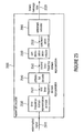
- Fig. 19 shows a schematic illustration of the basic concept 1900 for the synchronization, also called ABC synch. It shows a schematic illustration of an uncoded messages 1910, a coded message 1920 and a synchronization sequence (synch sequence) 1930 as well as the application of the synch to several messages 1920 following each other.
- the synchronization sequence or synch sequence mentioned in connection with the explanation of this synchronization concept may be equal to the synchronization signature mentioned before.
- Fig. 20 shows a schematic illustration of the synchronization found by correlating with the synch sequence. If the synchronization sequence 1930 is shorter than the message, more than one synchronization point 1940 (or alignment time block) may be found within a single message. In the example shown in Fig. 20 , 4 synchronization points are found within each message. Therefore, for each synchronization found, a Viterbi decoder (a Viterbi decoding sequence) may be started. In this way, for each synchronization point 1940 a message 2110 may be obtained, as indicated in Fig. 21 .
- the true messages 2210 may be identified by means of a CRC sequence (cyclic redundancy check sequence) and/or a plausibility check, as shown in Fig. 22 .
- CRC sequence cyclic redundancy check sequence
- plausibility check a plausibility check
- the CRC detection may use a known sequence to identify true messages from false positive.
- Fig. 23 shows an example for a CRC sequence added to the end of a payload.
- the probability of false positive may depend on the length of the CRC sequence and the number of Viterbi decoders (number of synchronization points within a single message) started.
- a plausibility may be exploited (plausibility test) or the length of the synchronization sequence (synchronization signature) may be increased.
- synchronization signal which we denote as synchronization signature
- sequences also designated as synchronization spread sequences
- Some conventional systems use special symbols (other than the ones used for the data), while some embodiments according to the invention do not use such special symbols.
- Other classical methods consist of embedding a known sequence of bits (preamble) time-multiplexed with the data, or embedding a signal frequency-multiplexed with the data.
- the method described herein is more advantageous as the method described herein allows to track changes in the synchronization (due e.g. to movement) continuously.
- the energy of the watermark signal is unchanged (e.g. by the multiplicative introduction of the watermark into the spread information representation), and the synchronization can be designed independent from the psychoacoustical model and data rate.
- the length in time of the synchronization signature which determines the robustness of the synchronization, can be designed at will completely independent of the data rate.
- Another classical method consists of embedding a synchronization sequence code-multiplexed with the data.
- the advantage of the method described herein is that the energy of the data does not represent an interfering factor in the computation of the correlation, bringing more robustness.
- code-multiplexing the number of orthogonal sequences available for the synchronization is reduced as some are necessary for the data.
- Some embodiments of the proposed system carry out spreading in both time and frequency domain, i.e. a 2-dimensional spreading (briefly designated as 2D-spreading). It has been found that this is advantageous with respect to 1D systems as the bit error rate can be further reduced by adding redundance in e.g. time domain.
- an increased robustness against movement and frequency mismatch of the local oscillators is brought by the differential modulation. It has been found that in fact, the Doppler effect (movement) and frequency mismatches lead to a rotation of the BPSK constellation (in other words, a rotation on the complex plane of the bits). In some embodiments, the detrimental effects of such a rotation of the BPSK constellation (or any other appropriate modulation constellation) are avoided by using a differential encoding or differential decoding.
- a different encoding concept or decoding concept may be applied.
- the differential encoding may be omitted.
- bit shaping brings along a significant improvement of the system performance, because the reliability of the detection can be increased using a filter adapted to the bit shaping.
- the usage of bit shaping with respect to watermarking brings along improved reliability of the watermarking process. It has been found that particularly good results can be obtained if the bit shaping function is longer than the bit interval.
- bit shaping may be applied. Also, in some cases, the bit shaping may be omitted.
- the psychoacoustical model interacts with the modulator to fine tune the amplitudes which multiply the bits.
- this interaction may be omitted.
- so called “Look back” and “look ahead” approaches are applied.
- the look ahead feature and/or the look back feature may be omitted.
- synchronization is performed in partial message synchronization mode with short synchronization signatures. For this reason many decodings have to be done, increasing the risk of false positive message detections. To prevent this, in some embodiments signaling sequences may be inserted into the messages with a lower bit rate as a consequence.
- a different concept for improving the synchronization robustness may be applied. Also, in some cases, the usage of any concepts for increasing the synchronization robustness may be omitted.
- Some embodiments according to the invention are better than conventional systems, which use very narrow bandwidths of, for example, 8Hz for the following reasons:
- the invention comprises a method to modify an audio signal in order to hide digital data and a corresponding decoder capable of retrieving this information while the perceived quality of the modified audio signal remains indistinguishable to the one of the original.
- aspects have been described in the context of an apparatus, it is clear that these aspects also represent a description of the corresponding method, where a block or device corresponds to a method step or a feature of a method step. Analogously, aspects described in the context of a method step also represent a description of a corresponding block or item or feature of a corresponding apparatus.
- Some or all of the method steps may be executed by (or using) a hardware apparatus, like for example, a microprocessor, a programmable computer or an electronic circuit. In some embodiments, some one or more of the most important method steps may be executed by such an apparatus.
- the inventive encoded watermark signal, or an audio signal into which the watermark signal is embedded can be stored on a digital storage medium or can be transmitted on a transmission medium such as a wireless transmission medium or a wired transmission medium such as the Internet.
- examples of the invention can be implemented in hardware or in software.
- the implementation can be performed using a digital storage medium, for example a floppy disk, a DVD, a Blue-Ray, a CD, a ROM, a PROM, an EPROM, an EEPROM or a FLASH memory, having electronically readable control signals stored thereon, which cooperate (or are capable of cooperating) with a programmable computer system such that the respective method is performed. Therefore, the digital storage medium may be computer readable.
- Some examples according to the invention comprise a data carrier having electronically readable control signals, which are capable of cooperating with a programmable computer system, such that one of the methods described herein is performed.
- examples of the present invention can be implemented as a computer program product with a program code, the program code being operative for performing one of the methods when the computer program product runs on a computer.
- the program code may for example be stored on a machine readable carrier.
- an example of the inventive method is, therefore, a computer program having a program code for performing one of the methods described herein, when the computer program runs on a computer.
- a further example of the inventive methods is, therefore, a data carrier (or a digital storage medium, or a computer-readable medium) comprising, recorded thereon, the computer program for performing one of the methods described herein.
- a further example of the inventive method is, therefore, a data stream or a sequence of signals representing the computer program for performing one of the methods described herein.
- the data stream or the sequence of signals may for example be configured to be transferred via a data communication connection, for example via the Internet.
- a further example comprises a processing means, for example a computer, or a programmable logic device, configured to or adapted to perform one of the methods described herein.
- a processing means for example a computer, or a programmable logic device, configured to or adapted to perform one of the methods described herein.
- a further example comprises a computer having installed thereon the computer program for performing one of the methods described herein.
- a programmable logic device for example a field programmable gate array
- a field programmable gate array may cooperate with a microprocessor in order to perform one of the methods described herein.
- the methods are preferably performed by any hardware apparatus.
Claims (15)
- Générateur de filigrane (101; 2400) pour fournir un signal de filigrane (101b; 2420) en fonction de données de message binaires (101a, m; 2410), le générateur de filigrane comprenant:un processeur d'information (303, 304, 305; 2430) configuré pour étaler les données de message binaires à une pluralité de bandes de fréquences ou de sous-bandes de fréquences et pour fournir, en fonction d'unités d'informations des données de message binaires, une première représentation dans le domaine temporel-fréquentiel (b(ij); 2432) dont les valeurs représentent les données de message binaires pour une pluralité de bandes de fréquences ou de sous-bandes de fréquences et de blocs temporels, où b(i,j) est le bit pour la i-ième bande de fréquences ou sous-bande de fréquences et le j-ième bloc temporel; etun codeur différentiel (306; 2440) configuré pour dériver une deuxième représentation dans le domaine temporel-fréquentiel (306a, bdiff(i,j); 2442) de la première représentation dans le domaine temporel-fréquentiel, de sorte que la deuxième représentation dans le domaine temporel-fréquentiel comprenne une pluralité de valeurs, où une valeur bdiff(i,j) de la deuxième représentation dans le domaine temporel-fréquentiel est fonction d'une valeur bdiff(i,j-1) de la deuxième représentation dans le domaine temporel-fréquentiel et d'une valeur b(i,j) de la première représentation dans le domaine temporel-fréquentiel et où une différence entre deux valeurs (bdiff(i,j), bdiff(i,j-1)) de la deuxième représentation dans le domaine temporel-fréquentiel représente une valeur correspondante de la première représentation dans le domaine temporel-fréquentiel, pour obtenir un codage différentiel des valeurs de la première représentation dans le domaine temporel-fréquentiel; etun fournisseur de signal de filigrane (307; 2450) configuré pour fournir le signal de filigrane sur base de la deuxième représentation dans le domaine temporel-fréquentiel.
- Générateur de filigrane selon la revendication 1, dans lequel le processeur d'informations est configuré pour fournir la première représentation dans le domaine temporel-fréquentiel de sorte que les valeurs de la première représentation dans le domaine temporel-fréquentiel représentent les données de message binaires sous forme de modèle binaire étalé; et
dans lequel le codeur différentiel est configuré pour dériver la deuxième représentation dans le domaine temporel-fréquentiel de sorte que soit introduit un changement de phase entre deux valeurs successives de la deuxième représentation dans le domaine temporel-fréquentiel si une valeur correspondante de la première représentation dans le domaine temporel-fréquentiel adopte une première valeur et de sorte qu'il n'y ait pas de changement de valeur entre deux valeurs successives de la deuxième représentation dans le domaine temporel-fréquentiel si une valeur correspondante de la première représentation dans le domaine temporel-fréquentiel adopte une deuxième valeur qui est différente de la première valeur. - Générateur de filigrane selon la revendication 2, dans lequel le processeur d'informations est configuré pour fournir une valeur de bit bdiff(i,j-1), associée à la i-ième bande de fréquences et le j-ième bloc temporel de la deuxième représentation dans le domaine temporel-fréquentiel de sorte que

où bdiff(i,j-1) désigne une valeur de bit associée à la i-ième bande de fréquences et au j-1-ième bloc temporel de la deuxième représentation dans le domaine temporel-fréquentiel;
où b(i,j) désigne une valeur de bit associée à la i-ième bande de fréquences et au j-ième bloc temporel de la première représentation dans le domaine temporel-fréquentiel; et
où les états binaires de la première représentation dans le domaine temporel-fréquentiel sont représentés par les valeurs +1 et -1. - Générateur de filigrane selon l'une des revendications 1 à 3, dans lequel le fournisseur de signal de filigrane est configuré pour fournir un signal audio combiné (107) sur base de la deuxième représentation dans le domaine temporel-fréquentiel, de sorte qu'une composante de filigrane du signal de filigrane comprenne un changement de phase par étapes ou lisse en réponse à une première valeur de la première représentation dans le domaine temporel-fréquentiel, et de sorte que la composante de fréquence de filigrane du signal de filigrane comprenne une phase constante dans le temps en réponse à une deuxième valeur de la première représentation dans le domaine temporel-fréquentiel qui est différente de la première valeur.
- Générateur de filigrane selon l'une des revendications 1 à 4, dans lequel le fournisseur du signal de filigrane est configuré pour fournir une première forme d'onde de formation de bit (giT(t)) en réponse à une première valeur de la deuxième représentation dans le domaine temporel-fréquentiel, et pour fournir une deuxième forme d'onde de formation de bit (-gi T(t)) en réponse à une deuxième valeur de la deuxième représentation dans le domaine temporel-fréquentiel, et
dans lequel le fournisseur de signal de filigrane est configuré pour inclure dans le signal de filigrane une superposition pondérée ou non pondérée de versions décalées dans le temps de la même forme d'onde de formation de bit en réponse à la présence d'une première valeur dans la première représentation dans le domaine temporel-fréquentiel, et pour inclure dans le signal de filigrane une superposition pondérée ou non pondérée de versions décalées dans le temps de la première forme d'onde de formation de bit et de la deuxième forme d'onde de formation de bit en réponse à la deuxième valeur qui est différente de la première valeur dans la première représentation dans le domaine temporel-fréquentiel. - Générateur de filigrane selon la revendication 5, dans lequel la deuxième forme d'onde de formation de bit est l'inverse de la première forme d'onde de formation de bit.
- Décodeur de filigrane (200; 2500) pour fournir des données de message binaires (202a; 2520) en fonction d'un signal à filigrane (200a; 2520), le décodeur de filigrane comprenant:un fournisseur de représentation dans le domaine temporel-fréquentiel (1600; 2530) configuré pour fournir une première représentation dans le domaine temporel-fréquentiel (bi norm(j); 2532) du signal à filigrane, où les valeurs bi norm(j) de la première représentation dans le domaine temporel-fréquentiel comprennent des informations sur la phase de composantes de signal à la fréquence fi et au moment j;un décodeur différentiel (1608; 2540) configuré pour dériver une deuxième représentation dans le domaine temporel-fréquentiel (b̂i(j); 2542) de la première représentation dans le domaine temporel-fréquentiel, de sorte que les valeurs de la deuxième représentation dans le domaine temporel-fréquentiel soient fonction de différences de phase entre deux valeurs correspondantes (bi norm(j), bi norm(j-1)) de la première représentation dans le domaine temporel-fréquentiel; etun déterminateur de synchronisation (201; 2550) configuré pour obtenir une information de synchronisation (205; 2552) sur base de la deuxième représentation dans le domaine temporel-fréquentiel; etun extracteur de filigrane (202; 2560) configuré pour extraire les données de message binaires de la première représentation dans le domaine temporel-fréquentiel du signal à filigrane ou de la deuxième représentation dans le domaine temporel-fréquentiel du signal à filigrane à l'aide des informations de synchronisation.
- Décodeur de filigrane (200; 2600) pour fournir des données de message binaires (202a; 2620) en fonction d'un signal à filigrane (200a; 2610), le décodeur de filigrane comprenant:un fournisseur de représentation dans le domaine temporel-fréquentiel (1600; 2630) configuré pour fournir une première représentation dans le domaine temporel-fréquentiel (bi norm(j); 2632) du signal à filigrane, où les valeurs bi norm(j) de la première représentation dans le domaine temporel-fréquentiel comprennent des informations sur la phase de composantes de signal à la fréquence fi et au moment j;un décodeur différentiel (1608; 2640) configuré pour dériver une deuxième représentation dans le domaine temporel-fréquentiel (bi(j); 2542) de la première représentation dans le domaine temporel-fréquentiel, de sorte que les valeurs de la deuxième représentation dans le domaine temporel-fréquentiel soient fonction de différences de phase entre deux valeurs correspondantes (bi norm(j), bi norm(j-1)) de la première représentation dans le domaine temporel-fréquentiel; etun extracteur de filigrane (202; 2650) configuré pour extraire les données de message binaires de la deuxième représentation dans le domaine temporel-fréquentiel.
- Décodeur de filigranes selon la revendication 7 ou la revendication 8, dans lequel le fournisseur de représentation dans le domaine temporel-fréquentiel est configuré pour fournir, pour une pluralité de bandes de fréquences et pour une pluralité d'intervalles de temps, des coefficients de bit doux (bi AFB(j), (bi norm(j)) décrivant une amplitude et une phase du signal à filigrane dans les bandes de fréquences et les intervalles de temps respectifs; et
dans lequel le décodeur différentiel est configuré pour déterminer une valeur (b̂i(j)) de la deuxième représentation dans le domaine temporel-fréquentiel associée à une bande de fréquences (fi) donnée et un intervalle de temps (j) donné sur base de deux valeurs correspondantes (bi norm(j), (bi norm(j-1)) de la première représentation dans le domaine temporel-fréquentiel. - Décodeur de filigrane selon l'une des revendications 7 à 9, dans lequel le décodeur de filigrane comprend un filtre d'analyse (1600) configuré pour convolutionner le signal à filigrane ou une version mélangée vers le bas de ce dernier avec une première fonction de formation de bit (giR(t)); et
dans lequel le décodeur de filigrane est configuré pour échantillonner dans le temps un résultat de la convolution, pour obtenir des valeurs discrètes dans le temps de la première représentation dans le domaine temporel-fréquentiel; et
lorsque le décodeur de filigrane est configuré pour ajuster une commande de temps utilisée pour l'échantillonnage du résultat de la convolution à une résolution d'intervalle de sous-bit en fonction d'une information de synchronisation, pour maximiser un rapport signal-bruit et pour minimiser un rapport d'interférence de symbole. - Décodeur de filigrane selon l'une des revendications 7 à 10, dans lequel le décodeur différentiel est configuré pour dériver la deuxième représentation dans le domaine temporel-fréquentiel indépendamment pour les différentes bandes de fréquences (fi), de sorte que différentes rotations de phase du signal à filigrane dans différentes bandes de fréquences soient compensées indépendamment par le décodeur différentiel; et
dans lequel le déterminateur de synchronisation ou le détecteur de filigrane est configuré pour traiter conjointement un ensemble de valeurs de la deuxième représentation dans le domaine temporel-fréquentiel associé à une partie de temps donnée et différentes bandes de fréquences, pour obtenir une information de synchronisation ou un bit des données de message binaires. - Dispositif d'évaluation de filigrane portable (2700), comprenant:un microphone (2710) configuré pour fournir un signal électrique de microphone (2712); etun décodeur de filigrane (2720) selon l'une des revendications 7 à 11, où le décodeur de filigrane est configuré pour recevoir un signal de microphone comme signal à filigrane.
- Procédé (2800) pour fournir un signal de filigrane en fonction de données de message binaires, le procédé comprenant:étaler les données de message binaires à une pluralité de bandes de fréquences ou sous-bandes de fréquences, pour fournir (2810), en fonction d'unités d'information des données de message binaires, une première représentation dans le domaine temporel-fréquentiel b(i,j), dont les valeurs représentent les données de message binaires pour une pluralité de bandes de fréquences ou sous-bandes de fréquences et blocs temporels, où b(i,j) est le bit pour la i-ième bande de fréquences ou sous-bande de fréquences et le j-ième bloc temporel;dériver (2820) une deuxième représentation dans le domaine temporel-fréquentiel de la première représentation dans le domaine temporel-fréquentiel, de sorte que la deuxième représentation dans le domaine temporel-fréquentiel comprenne une pluralité de valeurs, où une valeur bdiff(i,j) de la deuxième représentation dans le domaine temporel-fréquentiel est fonction d'une valeur bdiff(i,j-1) de la deuxième représentation dans le domaine temporel-fréquentiel et d'une valeur b(i,j) de la première représentation dans le domaine temporel-fréquentiel et où une différence entre deux valeurs de la deuxième représentation dans le domaine temporel-fréquentiel représente une valeur correspondante de la première représentation dans le domaine temporel-fréquentiel, pour obtenir un codage différentiel des valeurs de la première représentation dans le domaine temporel-fréquentiel; etfournir (2830) le signal de filigrane sur base de la deuxième représentation dans le domaine temporel-fréquentiel.
- Procédé (2900) pour fournir des données de message binaires en fonction d'un signal à filigrane, le procédé comprenant:fournir (2910) une première représentation dans le domaine temporel-fréquentiel du signal à filigrane où les valeurs bi norm(j) de la première représentation dans le domaine temporel-fréquentiel comprennent des informations sur la phase de composantes de signal à la fréquence fi et au moment j;dériver (2920) une deuxième représentation dans le domaine temporel-fréquentiel de la première représentation dans le domaine temporel-fréquentiel, de sorte que les valeurs de la deuxième représentation dans le domaine temporel-fréquentiel soient fonction de différences de phase entre deux valeurs correspondantes de la première représentation dans le domaine temporel-fréquentiel; etutiliser (2930) la deuxième représentation dans le domaine temporel-fréquentiel pour déterminer une information de synchronisation qui est utilisée pour fournir les données de message binaires, ou pour extraire les données de message binaires du signal à filigrane.
- Programme d'ordinateur adapté pour réaliser le procédé selon la revendication 13 ou la revendication 14, lorsque le programme d'ordinateur est exécuté sur un ordinateur.
Priority Applications (2)
| Application Number | Priority Date | Filing Date | Title |
|---|---|---|---|
| PL11706804T PL2522014T3 (pl) | 2010-02-26 | 2011-02-22 | Generator znaku wodnego, dekoder znaku wodnego, sposób dostarczania sygnału ze znakiem wodnym w zależności od danych komunikatu binarnego, sposób dostarczania danych komunikatu binarnego w zależności od sygnału ze znakiem wodnym i program komputerowy kodowanie różnicowe |
| EP11706804.9A EP2522014B1 (fr) | 2010-02-26 | 2011-02-22 | Générateur de filigrane, décodeur de filigrane, procédé de fourniture d'un signal de filigrane dépendant de données de message binaires, procédé de fourniture de données de message binaires dépendantes d'un signal de filigrane et programme informatique utilisant un codage différentiel |
Applications Claiming Priority (3)
| Application Number | Priority Date | Filing Date | Title |
|---|---|---|---|
| EP10154964A EP2362387A1 (fr) | 2010-02-26 | 2010-02-26 | Générateur de filigrane, décodeur de filigrane, procédé de fourniture d'un signal de filigrane dépendant de données de message binaires, procédé de fourniture de données de message binaires dépendantes d'un signal de filigrane et programme informatique utilisant un codage différentiel |
| PCT/EP2011/052614 WO2011104239A1 (fr) | 2010-02-26 | 2011-02-22 | Générateur de filigrane, décodeur de filigrane, procédé pour fournir un signal de filigrane en fonction de données de message binaires, procédé pour fournir des données de message binaires en fonction d'un signal contenant un filigrane et programme d'ordinateur utilisant un encodage différentiel |
| EP11706804.9A EP2522014B1 (fr) | 2010-02-26 | 2011-02-22 | Générateur de filigrane, décodeur de filigrane, procédé de fourniture d'un signal de filigrane dépendant de données de message binaires, procédé de fourniture de données de message binaires dépendantes d'un signal de filigrane et programme informatique utilisant un codage différentiel |
Publications (2)
| Publication Number | Publication Date |
|---|---|
| EP2522014A1 EP2522014A1 (fr) | 2012-11-14 |
| EP2522014B1 true EP2522014B1 (fr) | 2014-01-01 |
Family
ID=42274427
Family Applications (2)
| Application Number | Title | Priority Date | Filing Date |
|---|---|---|---|
| EP10154964A Withdrawn EP2362387A1 (fr) | 2010-02-26 | 2010-02-26 | Générateur de filigrane, décodeur de filigrane, procédé de fourniture d'un signal de filigrane dépendant de données de message binaires, procédé de fourniture de données de message binaires dépendantes d'un signal de filigrane et programme informatique utilisant un codage différentiel |
| EP11706804.9A Active EP2522014B1 (fr) | 2010-02-26 | 2011-02-22 | Générateur de filigrane, décodeur de filigrane, procédé de fourniture d'un signal de filigrane dépendant de données de message binaires, procédé de fourniture de données de message binaires dépendantes d'un signal de filigrane et programme informatique utilisant un codage différentiel |
Family Applications Before (1)
| Application Number | Title | Priority Date | Filing Date |
|---|---|---|---|
| EP10154964A Withdrawn EP2362387A1 (fr) | 2010-02-26 | 2010-02-26 | Générateur de filigrane, décodeur de filigrane, procédé de fourniture d'un signal de filigrane dépendant de données de message binaires, procédé de fourniture de données de message binaires dépendantes d'un signal de filigrane et programme informatique utilisant un codage différentiel |
Country Status (17)
| Country | Link |
|---|---|
| US (1) | US9350700B2 (fr) |
| EP (2) | EP2362387A1 (fr) |
| JP (1) | JP5567150B2 (fr) |
| KR (1) | KR101419162B1 (fr) |
| CN (1) | CN102859587B (fr) |
| AU (1) | AU2011219835B2 (fr) |
| BR (1) | BR112012021022B1 (fr) |
| CA (1) | CA2790648C (fr) |
| ES (1) | ES2449475T3 (fr) |
| HK (1) | HK1178667A1 (fr) |
| MX (1) | MX2012009861A (fr) |
| MY (1) | MY162294A (fr) |
| PL (1) | PL2522014T3 (fr) |
| RU (1) | RU2586844C2 (fr) |
| SG (1) | SG183457A1 (fr) |
| WO (1) | WO2011104239A1 (fr) |
| ZA (1) | ZA201207109B (fr) |
Families Citing this family (11)
| Publication number | Priority date | Publication date | Assignee | Title |
|---|---|---|---|---|
| EP2431970A1 (fr) | 2010-09-21 | 2012-03-21 | Fraunhofer-Gesellschaft zur Förderung der Angewandten Forschung e.V. | Générateur de filigrane, décodeur de filigrane, procédé de fourniture d'un signal de filigrane basé sur des données discrètes et procédé de fourniture de données discrètes dépendantes d'un signal de filigrane |
| EP2565667A1 (fr) | 2011-08-31 | 2013-03-06 | Friedrich-Alexander-Universität Erlangen-Nürnberg | Évaluation de direction d'arrivée à l'aide de signaux audio filigranés et réseaux de microphone |
| US9401153B2 (en) | 2012-10-15 | 2016-07-26 | Digimarc Corporation | Multi-mode audio recognition and auxiliary data encoding and decoding |
| US9305559B2 (en) | 2012-10-15 | 2016-04-05 | Digimarc Corporation | Audio watermark encoding with reversing polarity and pairwise embedding |
| EP2947650A1 (fr) * | 2013-01-18 | 2015-11-25 | Kabushiki Kaisha Toshiba | Synthétiseur de parole, dispositif de détection d'informations de filigrane électroniques, procédé de synthèse de parole, procédé de détection d'informations de filigrane électroniques, programme de synthèse vocale, et programme de détection d'informations de filigrane électroniques |
| US9317872B2 (en) | 2013-02-06 | 2016-04-19 | Muzak Llc | Encoding and decoding an audio watermark using key sequences comprising of more than two frequency components |
| US9093064B2 (en) * | 2013-03-11 | 2015-07-28 | The Nielsen Company (Us), Llc | Down-mixing compensation for audio watermarking |
| CN104573253B (zh) * | 2015-01-19 | 2017-09-19 | 江苏省特种设备安全监督检验研究院 | 压缩天然气加气站灾难后果预测方法 |
| US10062134B2 (en) * | 2016-06-24 | 2018-08-28 | The Nielsen Company (Us), Llc | Methods and apparatus to perform symbol-based watermark detection |
| RU2746708C1 (ru) * | 2020-07-29 | 2021-04-19 | Закрытое акционерное общество "Перспективный мониторинг" | Способ и устройство ввода водяного знака в аудиосигнал |
| WO2023212753A1 (fr) | 2022-05-02 | 2023-11-09 | Mediatest Research Gmbh | Procédé d'incorporation ou de décodage de données utiles d'un contenu audio |
Family Cites Families (35)
| Publication number | Priority date | Publication date | Assignee | Title |
|---|---|---|---|---|
| JPH02206233A (ja) | 1989-02-03 | 1990-08-16 | Fujitsu Ltd | 移動端末データモニタ方式 |
| FR2681997A1 (fr) | 1991-09-30 | 1993-04-02 | Arbitron Cy | Procede et dispositif d'identification automatique d'un programme comportant un signal sonore. |
| NZ259776A (en) | 1992-11-16 | 1997-06-24 | Ceridian Corp | Identifying recorded or broadcast audio signals by mixing with encoded signal derived from code signal modulated by narrower bandwidth identification signal |
| US7316025B1 (en) | 1992-11-16 | 2008-01-01 | Arbitron Inc. | Method and apparatus for encoding/decoding broadcast or recorded segments and monitoring audience exposure thereto |
| US7113615B2 (en) * | 1993-11-18 | 2006-09-26 | Digimarc Corporation | Watermark embedder and reader |
| WO1995027349A1 (fr) | 1994-03-31 | 1995-10-12 | The Arbitron Company, A Division Of Ceridian Corporation | Dispositifs et methodes d'incorporation et de decodage de codes dans des signaux audio |
| US5450490A (en) | 1994-03-31 | 1995-09-12 | The Arbitron Company | Apparatus and methods for including codes in audio signals and decoding |
| WO1997033391A1 (fr) | 1996-03-07 | 1997-09-12 | Fraunhofer-Gesellschaft zur Förderung der angewandten Forschung e.V. | Procede de codage pour introduire un signal de donnees non audible dans un signal audio, procede de decodage, codeur et decodeur correspondants |
| DE19640825C2 (de) | 1996-03-07 | 1998-07-23 | Fraunhofer Ges Forschung | Codierer zur Einbringung eines nicht hörbaren Datensignals in ein Audiosignal und Decodierer zum decodieren eines nicht hörbar in einem Audiosignal enthaltenen Datensignals |
| US6597961B1 (en) * | 1999-04-27 | 2003-07-22 | Realnetworks, Inc. | System and method for concealing errors in an audio transmission |
| GB9917985D0 (en) * | 1999-07-30 | 1999-09-29 | Scient Generics Ltd | Acoustic communication system |
| FR2802329B1 (fr) * | 1999-12-08 | 2003-03-28 | France Telecom | Procede de traitement d'au moins un flux binaire audio code organise sous la forme de trames |
| US6674876B1 (en) * | 2000-09-14 | 2004-01-06 | Digimarc Corporation | Watermarking in the time-frequency domain |
| BR0107444A (pt) | 2000-11-08 | 2002-10-08 | Koninkl Philips Electronics Nv | Método para comunicar um comando a um dispositivo controlável, arranjo para controlar remotamente um dispositivo controlável, dispositivo de controle arranjado para comunicar um comando em um primeiro domìnio para um dispositivo controlável, dispositivo controlável arranjado para receber um comando em um primeiro domìnio de um dispositivo de controle, produto de programa de computador, método para apresentar um anúncio para um usuário, e, sinal |
| RU2221284C2 (ru) * | 2002-02-26 | 2004-01-10 | Дочернее государственное унитарное научно-исследовательское предприятие "АРГУС" | Способ передачи и приема закодированной речи |
| EP1493155A1 (fr) | 2002-03-28 | 2005-01-05 | Koninklijke Philips Electronics N.V. | Fonctions de faconnage de fenetre pour le filigrane numerique de signaux multimedias |
| CN100359914C (zh) * | 2002-06-03 | 2008-01-02 | 皇家飞利浦电子股份有限公司 | 独立信道内的水印编码和解码 |
| WO2004010376A1 (fr) | 2002-07-22 | 2004-01-29 | Koninklijke Philips Electronics N.V. | Filigranoscopie |
| US7474756B2 (en) * | 2002-12-18 | 2009-01-06 | Siemens Corporate Research, Inc. | System and method for non-square blind source separation under coherent noise by beamforming and time-frequency masking |
| DE102004021404B4 (de) | 2004-04-30 | 2007-05-10 | Fraunhofer-Gesellschaft zur Förderung der angewandten Forschung e.V. | Wasserzeicheneinbettung |
| KR100644627B1 (ko) * | 2004-09-14 | 2006-11-10 | 삼성전자주식회사 | 음장 제어 정보 부호화 방법 및 이에 적합한 음장 처리 방법 |
| WO2006129293A1 (fr) | 2005-06-03 | 2006-12-07 | Koninklijke Philips Electronics N.V. | Chiffrement homomorphique pour filigrane securise |
| WO2007109064A1 (fr) * | 2006-03-17 | 2007-09-27 | Interdigital Technology Corporation | Procédé et appareil d'estimation de voie au moyen de pilotes localisés dans un domaine temps-fréquence et de techniques de débruitage |
| EP1837875A1 (fr) * | 2006-03-22 | 2007-09-26 | Deutsche Thomson-Brandt Gmbh | Procédé et appareil de mise en corrélation de deux sections de données |
| EP1898396A1 (fr) | 2006-09-07 | 2008-03-12 | Deutsche Thomson-Brandt Gmbh | Méthode et appareil pour la codage et décodage des symboles porteurs d'information pour le tatouage des signaux audio/vidéo |
| KR101434198B1 (ko) * | 2006-11-17 | 2014-08-26 | 삼성전자주식회사 | 신호 복호화 방법 |
| KR101379263B1 (ko) * | 2007-01-12 | 2014-03-28 | 삼성전자주식회사 | 대역폭 확장 복호화 방법 및 장치 |
| TWI374671B (en) * | 2007-07-31 | 2012-10-11 | Realtek Semiconductor Corp | Audio encoding method with function of accelerating a quantization iterative loop process |
| KR101456866B1 (ko) * | 2007-10-12 | 2014-11-03 | 삼성전자주식회사 | 혼합 사운드로부터 목표 음원 신호를 추출하는 방법 및장치 |
| DE102008014311A1 (de) | 2008-03-14 | 2009-09-17 | Fraunhofer-Gesellschaft zur Förderung der angewandten Forschung e.V. | Einbetter zum Einbetten eines Wasserzeichens in eine Informationsdarstellung, Detektor zum Detektieren eines Wasserzeichens in einer Informationsdarstellung, Verfahren, Computerprogramm und Informationssignal |
| JP5338170B2 (ja) * | 2008-07-18 | 2013-11-13 | ヤマハ株式会社 | 電子透かし情報の埋め込みおよび抽出を行う装置、方法およびプログラム |
| JP2010044147A (ja) * | 2008-08-11 | 2010-02-25 | Yamaha Corp | 電子透かし情報の埋め込みおよび抽出を行う装置、方法およびプログラム |
| WO2010148239A1 (fr) * | 2009-06-19 | 2010-12-23 | Dolby Laboratories Licensing Corporation | Commande de la hiérarchie et de l'ordre de traitement d'applications de traitement multimédia téléchargeables et évolutives |
| EP2362384A1 (fr) * | 2010-02-26 | 2011-08-31 | Fraunhofer-Gesellschaft zur Förderung der Angewandten Forschung e.V. | Générateur de filigrane, décodeur de filigrane, procédé de fourniture d'un signal de filigrane, procédé de fourniture de données de message binaires sur un signal de filigrane et programme informatisé utilisant un concept de synchronisation amélioré |
| US8676570B2 (en) * | 2010-04-26 | 2014-03-18 | The Nielsen Company (Us), Llc | Methods, apparatus and articles of manufacture to perform audio watermark decoding |
-
2010
- 2010-02-26 EP EP10154964A patent/EP2362387A1/fr not_active Withdrawn
-
2011
- 2011-02-22 MY MYPI2012003798A patent/MY162294A/en unknown
- 2011-02-22 PL PL11706804T patent/PL2522014T3/pl unknown
- 2011-02-22 WO PCT/EP2011/052614 patent/WO2011104239A1/fr active Application Filing
- 2011-02-22 RU RU2012140702/08A patent/RU2586844C2/ru active
- 2011-02-22 MX MX2012009861A patent/MX2012009861A/es active IP Right Grant
- 2011-02-22 CN CN201180020757.1A patent/CN102859587B/zh active Active
- 2011-02-22 BR BR112012021022-0A patent/BR112012021022B1/pt active IP Right Grant
- 2011-02-22 CA CA2790648A patent/CA2790648C/fr active Active
- 2011-02-22 AU AU2011219835A patent/AU2011219835B2/en active Active
- 2011-02-22 JP JP2012554324A patent/JP5567150B2/ja active Active
- 2011-02-22 KR KR1020127024977A patent/KR101419162B1/ko active IP Right Grant
- 2011-02-22 SG SG2012062501A patent/SG183457A1/en unknown
- 2011-02-22 ES ES11706804.9T patent/ES2449475T3/es active Active
- 2011-02-22 EP EP11706804.9A patent/EP2522014B1/fr active Active
-
2012
- 2012-02-21 ZA ZA2012/07109A patent/ZA201207109B/en unknown
- 2012-08-17 US US13/588,165 patent/US9350700B2/en active Active
-
2013
- 2013-05-02 HK HK13105315.2A patent/HK1178667A1/xx unknown
Also Published As
| Publication number | Publication date |
|---|---|
| US9350700B2 (en) | 2016-05-24 |
| CN102859587A (zh) | 2013-01-02 |
| AU2011219835A1 (en) | 2012-10-11 |
| BR112012021022B1 (pt) | 2021-08-03 |
| RU2012140702A (ru) | 2014-04-10 |
| MX2012009861A (es) | 2012-09-12 |
| WO2011104239A1 (fr) | 2011-09-01 |
| EP2362387A1 (fr) | 2011-08-31 |
| JP2013520694A (ja) | 2013-06-06 |
| EP2522014A1 (fr) | 2012-11-14 |
| PL2522014T3 (pl) | 2014-06-30 |
| KR20120128145A (ko) | 2012-11-26 |
| MY162294A (en) | 2017-05-31 |
| CN102859587B (zh) | 2014-11-05 |
| CA2790648C (fr) | 2017-02-28 |
| HK1178667A1 (en) | 2013-09-13 |
| RU2586844C2 (ru) | 2016-06-10 |
| US20130227295A1 (en) | 2013-08-29 |
| AU2011219835B2 (en) | 2014-08-14 |
| CA2790648A1 (fr) | 2011-09-01 |
| ES2449475T3 (es) | 2014-03-19 |
| ZA201207109B (en) | 2013-05-29 |
| JP5567150B2 (ja) | 2014-08-06 |
| BR112012021022A2 (pt) | 2017-09-26 |
| SG183457A1 (en) | 2012-09-27 |
| KR101419162B1 (ko) | 2014-07-11 |
Similar Documents
| Publication | Publication Date | Title |
|---|---|---|
| EP2539891B1 (fr) | Fournisseur de signal de filigrane et procédé de fourniture de signal de filigrane | |
| EP2539890B1 (fr) | Fourniture de signal de filigrane et insertion de filigrane | |
| EP2522014B1 (fr) | Générateur de filigrane, décodeur de filigrane, procédé de fourniture d'un signal de filigrane dépendant de données de message binaires, procédé de fourniture de données de message binaires dépendantes d'un signal de filigrane et programme informatique utilisant un codage différentiel | |
| EP2526548B1 (fr) | Générateur de filigrane, décodeur de filigrane, procédé de fourniture d'un signal de filigrane, procédé de fourniture de données de message binaires sur un signal de filigrane et programme informatisé utilisant un concept de synchronisation amélioré | |
| US8989885B2 (en) | Watermark generator, watermark decoder, method for providing a watermark signal in dependence on binary message data, method for providing binary message data in dependence on a watermarked signal and computer program using a two-dimensional bit spreading | |
| US9299356B2 (en) | Watermark decoder and method for providing binary message data |
Legal Events
| Date | Code | Title | Description |
|---|---|---|---|
| PUAI | Public reference made under article 153(3) epc to a published international application that has entered the european phase |
Free format text: ORIGINAL CODE: 0009012 |
|
| 17P | Request for examination filed |
Effective date: 20120809 |
|
| AK | Designated contracting states |
Kind code of ref document: A1 Designated state(s): AL AT BE BG CH CY CZ DE DK EE ES FI FR GB GR HR HU IE IS IT LI LT LU LV MC MK MT NL NO PL PT RO RS SE SI SK SM TR |
|
| REG | Reference to a national code |
Ref country code: DE Ref legal event code: R079 Ref document number: 602011004469 Country of ref document: DE Free format text: PREVIOUS MAIN CLASS: G10L0019000000 Ipc: G10L0019018000 |
|
| DAX | Request for extension of the european patent (deleted) | ||
| RIC1 | Information provided on ipc code assigned before grant |
Ipc: G10L 19/018 20130101AFI20130529BHEP |
|
| GRAP | Despatch of communication of intention to grant a patent |
Free format text: ORIGINAL CODE: EPIDOSNIGR1 |
|
| INTG | Intention to grant announced |
Effective date: 20130710 |
|
| RIN1 | Information on inventor provided before grant (corrected) |
Inventor name: BORSUM, JULIANE Inventor name: WABNIK, STEFAN Inventor name: BREILING, MARCO Inventor name: EBERLEIN, ERNST Inventor name: PICKEL, JOERG Inventor name: GRILL, BERNHARD Inventor name: BLIEM, TOBIAS Inventor name: KRAEGELOH, STEFAN Inventor name: ZITZMANN, REINHARD Inventor name: DEL GARDO, GIOVANNI Inventor name: GREEVENBOSCH, BERT |
|
| REG | Reference to a national code |
Ref country code: HK Ref legal event code: DE Ref document number: 1178667 Country of ref document: HK |
|
| GRAS | Grant fee paid |
Free format text: ORIGINAL CODE: EPIDOSNIGR3 |
|
| GRAA | (expected) grant |
Free format text: ORIGINAL CODE: 0009210 |
|
| AK | Designated contracting states |
Kind code of ref document: B1 Designated state(s): AL AT BE BG CH CY CZ DE DK EE ES FI FR GB GR HR HU IE IS IT LI LT LU LV MC MK MT NL NO PL PT RO RS SE SI SK SM TR |
|
| REG | Reference to a national code |
Ref country code: GB Ref legal event code: FG4D |
|
| REG | Reference to a national code |
Ref country code: CH Ref legal event code: EP |
|
| REG | Reference to a national code |
Ref country code: IE Ref legal event code: FG4D |
|
| REG | Reference to a national code |
Ref country code: AT Ref legal event code: REF Ref document number: 647891 Country of ref document: AT Kind code of ref document: T Effective date: 20140215 |
|
| REG | Reference to a national code |
Ref country code: DE Ref legal event code: R096 Ref document number: 602011004469 Country of ref document: DE Effective date: 20140220 |
|
| REG | Reference to a national code |
Ref country code: NL Ref legal event code: T3 |
|
| RIN2 | Information on inventor provided after grant (corrected) |
Inventor name: EBERLEIN, ERNST Inventor name: ZITZMANN, REINHARD Inventor name: GRILL, BERNHARD Inventor name: KRAEGELOH, STEFAN Inventor name: BLIEM, TOBIAS Inventor name: GREEVENBOSCH, BERT Inventor name: PICKEL, JOERG Inventor name: BREILING, MARCO Inventor name: BORSUM, JULIANE Inventor name: WABNIK, STEFAN Inventor name: DEL GALDO, GIOVANNI |
|
| REG | Reference to a national code |
Ref country code: ES Ref legal event code: FG2A Ref document number: 2449475 Country of ref document: ES Kind code of ref document: T3 Effective date: 20140319 |
|
| REG | Reference to a national code |
Ref country code: HK Ref legal event code: GR Ref document number: 1178667 Country of ref document: HK |
|
| REG | Reference to a national code |
Ref country code: DE Ref legal event code: R083 Ref document number: 602011004469 Country of ref document: DE |
|
| REG | Reference to a national code |
Ref country code: AT Ref legal event code: MK05 Ref document number: 647891 Country of ref document: AT Kind code of ref document: T Effective date: 20140101 |
|
| REG | Reference to a national code |
Ref country code: LT Ref legal event code: MG4D |
|
| REG | Reference to a national code |
Ref country code: PL Ref legal event code: T3 |
|
| PG25 | Lapsed in a contracting state [announced via postgrant information from national office to epo] |
Ref country code: LT Free format text: LAPSE BECAUSE OF FAILURE TO SUBMIT A TRANSLATION OF THE DESCRIPTION OR TO PAY THE FEE WITHIN THE PRESCRIBED TIME-LIMIT Effective date: 20140101 Ref country code: IS Free format text: LAPSE BECAUSE OF FAILURE TO SUBMIT A TRANSLATION OF THE DESCRIPTION OR TO PAY THE FEE WITHIN THE PRESCRIBED TIME-LIMIT Effective date: 20140501 |
|
| PG25 | Lapsed in a contracting state [announced via postgrant information from national office to epo] |
Ref country code: CY Free format text: LAPSE BECAUSE OF FAILURE TO SUBMIT A TRANSLATION OF THE DESCRIPTION OR TO PAY THE FEE WITHIN THE PRESCRIBED TIME-LIMIT Effective date: 20140101 Ref country code: AT Free format text: LAPSE BECAUSE OF FAILURE TO SUBMIT A TRANSLATION OF THE DESCRIPTION OR TO PAY THE FEE WITHIN THE PRESCRIBED TIME-LIMIT Effective date: 20140101 Ref country code: SE Free format text: LAPSE BECAUSE OF FAILURE TO SUBMIT A TRANSLATION OF THE DESCRIPTION OR TO PAY THE FEE WITHIN THE PRESCRIBED TIME-LIMIT Effective date: 20140101 Ref country code: PT Free format text: LAPSE BECAUSE OF FAILURE TO SUBMIT A TRANSLATION OF THE DESCRIPTION OR TO PAY THE FEE WITHIN THE PRESCRIBED TIME-LIMIT Effective date: 20140502 Ref country code: FI Free format text: LAPSE BECAUSE OF FAILURE TO SUBMIT A TRANSLATION OF THE DESCRIPTION OR TO PAY THE FEE WITHIN THE PRESCRIBED TIME-LIMIT Effective date: 20140101 |
|
| PG25 | Lapsed in a contracting state [announced via postgrant information from national office to epo] |
Ref country code: LV Free format text: LAPSE BECAUSE OF FAILURE TO SUBMIT A TRANSLATION OF THE DESCRIPTION OR TO PAY THE FEE WITHIN THE PRESCRIBED TIME-LIMIT Effective date: 20140101 Ref country code: HR Free format text: LAPSE BECAUSE OF FAILURE TO SUBMIT A TRANSLATION OF THE DESCRIPTION OR TO PAY THE FEE WITHIN THE PRESCRIBED TIME-LIMIT Effective date: 20140101 Ref country code: RS Free format text: LAPSE BECAUSE OF FAILURE TO SUBMIT A TRANSLATION OF THE DESCRIPTION OR TO PAY THE FEE WITHIN THE PRESCRIBED TIME-LIMIT Effective date: 20140101 |
|
| REG | Reference to a national code |
Ref country code: CH Ref legal event code: PL |
|
| REG | Reference to a national code |
Ref country code: DE Ref legal event code: R097 Ref document number: 602011004469 Country of ref document: DE |
|
| PG25 | Lapsed in a contracting state [announced via postgrant information from national office to epo] |
Ref country code: CH Free format text: LAPSE BECAUSE OF NON-PAYMENT OF DUE FEES Effective date: 20140228 Ref country code: MC Free format text: LAPSE BECAUSE OF FAILURE TO SUBMIT A TRANSLATION OF THE DESCRIPTION OR TO PAY THE FEE WITHIN THE PRESCRIBED TIME-LIMIT Effective date: 20140101 Ref country code: CZ Free format text: LAPSE BECAUSE OF FAILURE TO SUBMIT A TRANSLATION OF THE DESCRIPTION OR TO PAY THE FEE WITHIN THE PRESCRIBED TIME-LIMIT Effective date: 20140101 Ref country code: RO Free format text: LAPSE BECAUSE OF FAILURE TO SUBMIT A TRANSLATION OF THE DESCRIPTION OR TO PAY THE FEE WITHIN THE PRESCRIBED TIME-LIMIT Effective date: 20140101 Ref country code: LI Free format text: LAPSE BECAUSE OF NON-PAYMENT OF DUE FEES Effective date: 20140228 Ref country code: DK Free format text: LAPSE BECAUSE OF FAILURE TO SUBMIT A TRANSLATION OF THE DESCRIPTION OR TO PAY THE FEE WITHIN THE PRESCRIBED TIME-LIMIT Effective date: 20140101 Ref country code: EE Free format text: LAPSE BECAUSE OF FAILURE TO SUBMIT A TRANSLATION OF THE DESCRIPTION OR TO PAY THE FEE WITHIN THE PRESCRIBED TIME-LIMIT Effective date: 20140101 |
|
| PLBE | No opposition filed within time limit |
Free format text: ORIGINAL CODE: 0009261 |
|
| STAA | Information on the status of an ep patent application or granted ep patent |
Free format text: STATUS: NO OPPOSITION FILED WITHIN TIME LIMIT |
|
| PG25 | Lapsed in a contracting state [announced via postgrant information from national office to epo] |
Ref country code: SK Free format text: LAPSE BECAUSE OF FAILURE TO SUBMIT A TRANSLATION OF THE DESCRIPTION OR TO PAY THE FEE WITHIN THE PRESCRIBED TIME-LIMIT Effective date: 20140101 |
|
| REG | Reference to a national code |
Ref country code: IE Ref legal event code: MM4A |
|
| 26N | No opposition filed |
Effective date: 20141002 |
|
| REG | Reference to a national code |
Ref country code: DE Ref legal event code: R097 Ref document number: 602011004469 Country of ref document: DE Effective date: 20141002 |
|
| PG25 | Lapsed in a contracting state [announced via postgrant information from national office to epo] |
Ref country code: IE Free format text: LAPSE BECAUSE OF NON-PAYMENT OF DUE FEES Effective date: 20140222 |
|
| PG25 | Lapsed in a contracting state [announced via postgrant information from national office to epo] |
Ref country code: SI Free format text: LAPSE BECAUSE OF FAILURE TO SUBMIT A TRANSLATION OF THE DESCRIPTION OR TO PAY THE FEE WITHIN THE PRESCRIBED TIME-LIMIT Effective date: 20140101 |
|
| REG | Reference to a national code |
Ref country code: FR Ref legal event code: PLFP Year of fee payment: 6 |
|
| PG25 | Lapsed in a contracting state [announced via postgrant information from national office to epo] |
Ref country code: MT Free format text: LAPSE BECAUSE OF FAILURE TO SUBMIT A TRANSLATION OF THE DESCRIPTION OR TO PAY THE FEE WITHIN THE PRESCRIBED TIME-LIMIT Effective date: 20140101 |
|
| PG25 | Lapsed in a contracting state [announced via postgrant information from national office to epo] |
Ref country code: NO Free format text: LAPSE BECAUSE OF FAILURE TO SUBMIT A TRANSLATION OF THE DESCRIPTION OR TO PAY THE FEE WITHIN THE PRESCRIBED TIME-LIMIT Effective date: 20140401 Ref country code: SM Free format text: LAPSE BECAUSE OF FAILURE TO SUBMIT A TRANSLATION OF THE DESCRIPTION OR TO PAY THE FEE WITHIN THE PRESCRIBED TIME-LIMIT Effective date: 20140101 |
|
| PG25 | Lapsed in a contracting state [announced via postgrant information from national office to epo] |
Ref country code: BG Free format text: LAPSE BECAUSE OF FAILURE TO SUBMIT A TRANSLATION OF THE DESCRIPTION OR TO PAY THE FEE WITHIN THE PRESCRIBED TIME-LIMIT Effective date: 20140101 Ref country code: GR Free format text: LAPSE BECAUSE OF FAILURE TO SUBMIT A TRANSLATION OF THE DESCRIPTION OR TO PAY THE FEE WITHIN THE PRESCRIBED TIME-LIMIT Effective date: 20140402 |
|
| PG25 | Lapsed in a contracting state [announced via postgrant information from national office to epo] |
Ref country code: LU Free format text: LAPSE BECAUSE OF NON-PAYMENT OF DUE FEES Effective date: 20140222 Ref country code: HU Free format text: LAPSE BECAUSE OF FAILURE TO SUBMIT A TRANSLATION OF THE DESCRIPTION OR TO PAY THE FEE WITHIN THE PRESCRIBED TIME-LIMIT; INVALID AB INITIO Effective date: 20110222 |
|
| REG | Reference to a national code |
Ref country code: FR Ref legal event code: PLFP Year of fee payment: 7 |
|
| REG | Reference to a national code |
Ref country code: FR Ref legal event code: PLFP Year of fee payment: 8 |
|
| PG25 | Lapsed in a contracting state [announced via postgrant information from national office to epo] |
Ref country code: MK Free format text: LAPSE BECAUSE OF FAILURE TO SUBMIT A TRANSLATION OF THE DESCRIPTION OR TO PAY THE FEE WITHIN THE PRESCRIBED TIME-LIMIT Effective date: 20140101 |
|
| PG25 | Lapsed in a contracting state [announced via postgrant information from national office to epo] |
Ref country code: AL Free format text: LAPSE BECAUSE OF FAILURE TO SUBMIT A TRANSLATION OF THE DESCRIPTION OR TO PAY THE FEE WITHIN THE PRESCRIBED TIME-LIMIT Effective date: 20140101 |
|
| PGFP | Annual fee paid to national office [announced via postgrant information from national office to epo] |
Ref country code: NL Payment date: 20230220 Year of fee payment: 13 |
|
| PGFP | Annual fee paid to national office [announced via postgrant information from national office to epo] |
Ref country code: FR Payment date: 20230220 Year of fee payment: 13 Ref country code: ES Payment date: 20230317 Year of fee payment: 13 |
|
| PGFP | Annual fee paid to national office [announced via postgrant information from national office to epo] |
Ref country code: TR Payment date: 20230222 Year of fee payment: 13 Ref country code: PL Payment date: 20230214 Year of fee payment: 13 Ref country code: IT Payment date: 20230228 Year of fee payment: 13 Ref country code: GB Payment date: 20230221 Year of fee payment: 13 Ref country code: DE Payment date: 20230216 Year of fee payment: 13 Ref country code: BE Payment date: 20230220 Year of fee payment: 13 |
|
| P01 | Opt-out of the competence of the unified patent court (upc) registered |
Effective date: 20230512 |
|
| PGFP | Annual fee paid to national office [announced via postgrant information from national office to epo] |
Ref country code: NL Payment date: 20240220 Year of fee payment: 14 |