EP2521908B1 - Intelligentes sensorsystem mit einem elektroaktiven polymer - Google Patents
Intelligentes sensorsystem mit einem elektroaktiven polymer Download PDFInfo
- Publication number
- EP2521908B1 EP2521908B1 EP10724737.1A EP10724737A EP2521908B1 EP 2521908 B1 EP2521908 B1 EP 2521908B1 EP 10724737 A EP10724737 A EP 10724737A EP 2521908 B1 EP2521908 B1 EP 2521908B1
- Authority
- EP
- European Patent Office
- Prior art keywords
- potentiostat
- output signal
- working electrode
- current
- potential
- Prior art date
- Legal status (The legal status is an assumption and is not a legal conclusion. Google has not performed a legal analysis and makes no representation as to the accuracy of the status listed.)
- Not-in-force
Links
- 229920001746 electroactive polymer Polymers 0.000 title 1
- 229920000767 polyaniline Polymers 0.000 claims description 37
- 239000007787 solid Substances 0.000 claims description 18
- 238000000034 method Methods 0.000 claims description 17
- 229920000642 polymer Polymers 0.000 claims description 11
- 102000004190 Enzymes Human genes 0.000 claims description 8
- 108090000790 Enzymes Proteins 0.000 claims description 8
- 108090000204 Dipeptidase 1 Proteins 0.000 claims description 5
- 102000006635 beta-lactamase Human genes 0.000 claims description 5
- 230000010355 oscillation Effects 0.000 claims description 5
- 229920000128 polypyrrole Polymers 0.000 claims description 3
- 238000005259 measurement Methods 0.000 description 19
- 239000000243 solution Substances 0.000 description 14
- 238000001514 detection method Methods 0.000 description 12
- 229910021607 Silver chloride Inorganic materials 0.000 description 10
- HKZLPVFGJNLROG-UHFFFAOYSA-M silver monochloride Chemical compound [Cl-].[Ag+] HKZLPVFGJNLROG-UHFFFAOYSA-M 0.000 description 10
- PAYRUJLWNCNPSJ-UHFFFAOYSA-N Aniline Chemical compound NC1=CC=CC=C1 PAYRUJLWNCNPSJ-UHFFFAOYSA-N 0.000 description 8
- 238000010586 diagram Methods 0.000 description 8
- 238000002474 experimental method Methods 0.000 description 6
- BASFCYQUMIYNBI-UHFFFAOYSA-N platinum Chemical compound [Pt] BASFCYQUMIYNBI-UHFFFAOYSA-N 0.000 description 6
- 239000000126 substance Substances 0.000 description 6
- RYGMFSIKBFXOCR-UHFFFAOYSA-N Copper Chemical compound [Cu] RYGMFSIKBFXOCR-UHFFFAOYSA-N 0.000 description 5
- JGSARLDLIJGVTE-MBNYWOFBSA-N Penicillin G Chemical compound N([C@H]1[C@H]2SC([C@@H](N2C1=O)C(O)=O)(C)C)C(=O)CC1=CC=CC=C1 JGSARLDLIJGVTE-MBNYWOFBSA-N 0.000 description 5
- 239000007864 aqueous solution Substances 0.000 description 5
- 229910052802 copper Inorganic materials 0.000 description 5
- 239000010949 copper Substances 0.000 description 5
- 230000003247 decreasing effect Effects 0.000 description 5
- 238000004313 potentiometry Methods 0.000 description 5
- 238000003786 synthesis reaction Methods 0.000 description 5
- 229910000497 Amalgam Inorganic materials 0.000 description 4
- 239000000872 buffer Substances 0.000 description 4
- 239000007853 buffer solution Substances 0.000 description 4
- 230000007423 decrease Effects 0.000 description 4
- 230000000694 effects Effects 0.000 description 4
- 239000000463 material Substances 0.000 description 4
- 230000015572 biosynthetic process Effects 0.000 description 3
- 230000008020 evaporation Effects 0.000 description 3
- 238000001704 evaporation Methods 0.000 description 3
- 238000001139 pH measurement Methods 0.000 description 3
- 229910052697 platinum Inorganic materials 0.000 description 3
- 230000004044 response Effects 0.000 description 3
- 239000000758 substrate Substances 0.000 description 3
- XKRFYHLGVUSROY-UHFFFAOYSA-N Argon Chemical compound [Ar] XKRFYHLGVUSROY-UHFFFAOYSA-N 0.000 description 2
- VYPSYNLAJGMNEJ-UHFFFAOYSA-N Silicium dioxide Chemical compound O=[Si]=O VYPSYNLAJGMNEJ-UHFFFAOYSA-N 0.000 description 2
- 230000009471 action Effects 0.000 description 2
- 230000004075 alteration Effects 0.000 description 2
- 238000013459 approach Methods 0.000 description 2
- 238000004590 computer program Methods 0.000 description 2
- 125000004122 cyclic group Chemical group 0.000 description 2
- 238000000157 electrochemical-induced impedance spectroscopy Methods 0.000 description 2
- 229910052737 gold Inorganic materials 0.000 description 2
- 239000010931 gold Substances 0.000 description 2
- 239000000203 mixture Substances 0.000 description 2
- 229940056360 penicillin g Drugs 0.000 description 2
- 230000008569 process Effects 0.000 description 2
- 229910052709 silver Inorganic materials 0.000 description 2
- 239000004332 silver Substances 0.000 description 2
- 239000010936 titanium Substances 0.000 description 2
- 238000004832 voltammetry Methods 0.000 description 2
- KXGFMDJXCMQABM-UHFFFAOYSA-N 2-methoxy-6-methylphenol Chemical compound [CH]OC1=CC=CC([CH])=C1O KXGFMDJXCMQABM-UHFFFAOYSA-N 0.000 description 1
- 229910021578 Iron(III) chloride Inorganic materials 0.000 description 1
- XOJVVFBFDXDTEG-UHFFFAOYSA-N Norphytane Natural products CC(C)CCCC(C)CCCC(C)CCCC(C)C XOJVVFBFDXDTEG-UHFFFAOYSA-N 0.000 description 1
- 229930182555 Penicillin Natural products 0.000 description 1
- 206010034972 Photosensitivity reaction Diseases 0.000 description 1
- 229910052581 Si3N4 Inorganic materials 0.000 description 1
- XUIMIQQOPSSXEZ-UHFFFAOYSA-N Silicon Chemical compound [Si] XUIMIQQOPSSXEZ-UHFFFAOYSA-N 0.000 description 1
- RTAQQCXQSZGOHL-UHFFFAOYSA-N Titanium Chemical compound [Ti] RTAQQCXQSZGOHL-UHFFFAOYSA-N 0.000 description 1
- 239000002253 acid Substances 0.000 description 1
- 230000004913 activation Effects 0.000 description 1
- 230000032683 aging Effects 0.000 description 1
- 239000003242 anti bacterial agent Substances 0.000 description 1
- 229940088710 antibiotic agent Drugs 0.000 description 1
- 229910052786 argon Inorganic materials 0.000 description 1
- 239000000090 biomarker Substances 0.000 description 1
- 229910052799 carbon Inorganic materials 0.000 description 1
- 230000008859 change Effects 0.000 description 1
- 238000006243 chemical reaction Methods 0.000 description 1
- 239000003795 chemical substances by application Substances 0.000 description 1
- 229910052681 coesite Inorganic materials 0.000 description 1
- 229910052906 cristobalite Inorganic materials 0.000 description 1
- 238000000151 deposition Methods 0.000 description 1
- 230000008021 deposition Effects 0.000 description 1
- 238000013461 design Methods 0.000 description 1
- 238000009792 diffusion process Methods 0.000 description 1
- 238000007599 discharging Methods 0.000 description 1
- 229920000775 emeraldine polymer Polymers 0.000 description 1
- 230000005284 excitation Effects 0.000 description 1
- PCHJSUWPFVWCPO-UHFFFAOYSA-N gold Chemical compound [Au] PCHJSUWPFVWCPO-UHFFFAOYSA-N 0.000 description 1
- 230000007062 hydrolysis Effects 0.000 description 1
- 238000006460 hydrolysis reaction Methods 0.000 description 1
- RBTARNINKXHZNM-UHFFFAOYSA-K iron trichloride Chemical compound Cl[Fe](Cl)Cl RBTARNINKXHZNM-UHFFFAOYSA-K 0.000 description 1
- 239000007788 liquid Substances 0.000 description 1
- 230000007246 mechanism Effects 0.000 description 1
- 238000000399 optical microscopy Methods 0.000 description 1
- 230000003647 oxidation Effects 0.000 description 1
- 238000007254 oxidation reaction Methods 0.000 description 1
- 239000006174 pH buffer Substances 0.000 description 1
- 229910052763 palladium Inorganic materials 0.000 description 1
- KDLHZDBZIXYQEI-UHFFFAOYSA-N palladium Substances [Pd] KDLHZDBZIXYQEI-UHFFFAOYSA-N 0.000 description 1
- 229940049954 penicillin Drugs 0.000 description 1
- 239000005011 phenolic resin Substances 0.000 description 1
- 229920001568 phenolic resin Polymers 0.000 description 1
- 238000000206 photolithography Methods 0.000 description 1
- 238000004375 physisorption Methods 0.000 description 1
- 238000000623 plasma-assisted chemical vapour deposition Methods 0.000 description 1
- 230000005588 protonation Effects 0.000 description 1
- 238000004626 scanning electron microscopy Methods 0.000 description 1
- 230000035945 sensitivity Effects 0.000 description 1
- 229910052710 silicon Inorganic materials 0.000 description 1
- 239000010703 silicon Substances 0.000 description 1
- 239000000377 silicon dioxide Substances 0.000 description 1
- 235000012239 silicon dioxide Nutrition 0.000 description 1
- HQVNEWCFYHHQES-UHFFFAOYSA-N silicon nitride Chemical compound N12[Si]34N5[Si]62N3[Si]51N64 HQVNEWCFYHHQES-UHFFFAOYSA-N 0.000 description 1
- 238000005549 size reduction Methods 0.000 description 1
- 238000001179 sorption measurement Methods 0.000 description 1
- 229910052682 stishovite Inorganic materials 0.000 description 1
- 238000010408 sweeping Methods 0.000 description 1
- 229910052719 titanium Inorganic materials 0.000 description 1
- 229910052905 tridymite Inorganic materials 0.000 description 1
- 150000003952 β-lactams Chemical class 0.000 description 1
Images


Classifications
-
- G—PHYSICS
- G01—MEASURING; TESTING
- G01N—INVESTIGATING OR ANALYSING MATERIALS BY DETERMINING THEIR CHEMICAL OR PHYSICAL PROPERTIES
- G01N27/00—Investigating or analysing materials by the use of electric, electrochemical, or magnetic means
- G01N27/26—Investigating or analysing materials by the use of electric, electrochemical, or magnetic means by investigating electrochemical variables; by using electrolysis or electrophoresis
- G01N27/416—Systems
- G01N27/4161—Systems measuring the voltage and using a constant current supply, e.g. chronopotentiometry
-
- G—PHYSICS
- G01—MEASURING; TESTING
- G01N—INVESTIGATING OR ANALYSING MATERIALS BY DETERMINING THEIR CHEMICAL OR PHYSICAL PROPERTIES
- G01N27/00—Investigating or analysing materials by the use of electric, electrochemical, or magnetic means
- G01N27/26—Investigating or analysing materials by the use of electric, electrochemical, or magnetic means by investigating electrochemical variables; by using electrolysis or electrophoresis
- G01N27/416—Systems
- G01N27/4166—Systems measuring a particular property of an electrolyte
- G01N27/4167—Systems measuring a particular property of an electrolyte pH
-
- G—PHYSICS
- G01—MEASURING; TESTING
- G01N—INVESTIGATING OR ANALYSING MATERIALS BY DETERMINING THEIR CHEMICAL OR PHYSICAL PROPERTIES
- G01N27/00—Investigating or analysing materials by the use of electric, electrochemical, or magnetic means
- G01N27/26—Investigating or analysing materials by the use of electric, electrochemical, or magnetic means by investigating electrochemical variables; by using electrolysis or electrophoresis
- G01N27/28—Electrolytic cell components
- G01N27/30—Electrodes, e.g. test electrodes; Half-cells
- G01N27/333—Ion-selective electrodes or membranes
- G01N27/3335—Ion-selective electrodes or membranes the membrane containing at least one organic component
Definitions
- the invention relates to the field of system for measuring a solution pH comprising a potentiostat with a working electrode made of an electro-conductive solid polymer transducer.
- Polyaniline is a very convenient material when used as a solid electrochemical transducer owing to its many interesting intrinsic combinations of redox and acido-basic states. This polymer is known as stable and highly conductive in its emeraldine acid form.
- Polyaniline also makes it possible to chemically, i.e. by chemical grafting, or physically, i.e. by physisorption, sensitize its surface with natural or engineered biochemical agents for biosensing purposes.
- some enzymes are well known to release protons from their specific substrate hydrolysis. This allows to develop sensors based on a proton releasing enzyme mediator.
- the polyaniline protonation state strongly affects the equilibria between its redox states.
- This material can be electrochemically characterized to indicate the pH of an aqueous solution.
- a simple potentiometry measurement of a polyaniline covered working electrode against a reference electrode displays a simple nernstian behavior as a function of the proton concentration.
- This simple system similar to a conventional combined pH electrode, can be viewed as a battery cell having a limited charge and producing its own potential difference proportional to pH.
- the two electrodes potentiometry measurements are passive: a constant discharging of the cell, through its internal resistance and through the high impedance measuring voltmeter, occurs. This can, in some cases, cause unwanted alteration of polyaniline redox states and cause a drift in the measured potentials. It is as though the reference and working electrodes were pulling each other's electrochemical potential to annul their difference by a small current exchange through the solution and the measuring instrument internal impedance. This drawback effect can be easily rendered negligible by using large surface working electrodes, thus increasing the available charge, but can however completely prevent reliable measurements at the micro and nano scales. Moreover, polyaniline electrochemical impedance varies simultaneously as a function of both the pH and its electrochemical potential.
- electrochemical sensors that are supposed to be used more than once or during long periods of time, favor the use of a continuous actuation during sensing rather than a supplementary differed protocol for electrochemical resetting or reloading.
- the actuation channel has to control, as best it can, some interface physico-chemical properties such as redox, acid-base and dielectric activities. This actuation is made in order to keep the transducer properties as unchanged as possible while observing at the same time how the system proceeds to do so in its feedback control.
- different actuations could lead to either increased selectivity or sensitivity or precision, starting from initially identical micro or nano-sensors.
- a potentiostat is a control and measuring device using three electrodes: a working electrode, a reference electrode and a counter electrode.
- a basic use of a potentiostat consists to consider it as an electric circuit which controls the potential across the cell by sensing changes in its impedance, varying accordingly the current supplied to the system: a higher impedance will result in a decreased current, while a lower impedance will result in an increased current, in order to keep the voltage constant.
- the variable system impedance and the controlled current are inversely proportional.
- I o is the output electrical current of the potentiostat
- E c is the input voltage that is kept constant
- R v is the electrical impedance that varies.
- the potentiostat, Figure 1 in its conventional architecture needs thus an input signal E c , which is the difference in potential to be applied between the working electrode W and the reference electrode R. Then, the potentiostat generates an output signal U out that is proportional to the magnitude of the current flowing between the counter electrode C and the working electrode W. The current flow serves to maintain the working electrode W at the desired potential against the reference electrode's one.
- This system can be considered as the imbrications of operational amplifiers (Integrated Circuit, IC) into an analogue feedback loop.
- A1 is used as an adder
- A2 as a voltage follower
- A3 as a current to voltage converter scaled by a selected resistance R3.
- a system for measuring a pH solution comprises:
- the digital processor is adapted to modify the potentiostat input signal in order to maintain the output signal inside a predetermined range such that the input signal potential is representative of the solution pH when the output signal is inside the predetermined range.
- a particular embodiment may be preferred as easier to adapt or as giving a better result. Aspects of these particular embodiments may be combined or modified as appropriate or desired, however.
- a system for sensing biological molecules comprises a system as here above, wherein the electro-conductive solid polymer transducer is sensitized by a proton releasing enzyme mediator.
- the proton releasing enzyme mediator comprises a ⁇ -lactamase enzyme.
- a method measures a solution pH with a potentiostat, the potentiostat comprising a working electrode made of an electro-conductive solid polymer transducer, an input to receive an input signal indicative of the potential to be applied between the working electrode and a reference electrode of the potentiostat, and an output to transmit an output signal indicative of the magnitude of the current flowing between a counter electrode of the potentiostat and the working electrode, the three electrodes being immerged into said solution.
- the method comprises:
- a computer software product stored on a recording media comprises a set of instructions to enable a computer to practice the here above method when the computer executes the set of instructions.
- a potentiostat 1 comprises a cell 3 of three electrodes: a working electrode W, a reference electrode R and a counter electrode C.
- the counter electrode C is connected to the output of an operational amplifier 5 of which one input is connected to ground and the second input is connected through a resistance 7 to an input connector 9.
- a second operational amplifier 11 has a first input connected to the reference electrode R and its second input connected to its output and, through a second resistance 13, to the second input of the first operational amplifier 5.
- the working electrode W is connected to a first input of a third operational amplifier 15, the second input of the third operational amplifier being connected to ground and its output being connected to output connector 17 of the potentiostat.
- a resistance selector 19, called hereafter a multiplexer, is connected in parallel of the third operational amplifier 15 to the working electrode W and the output connector 17.
- a computer 21 comprises a digital processor 23 connected to a digital to analog converter DAC 25 and to an analog to digital converter ADC 27.
- the DAC is connected to the input connector 9 of the potentiostat 1 and the ADC to its output connector 17.
- the computer 21 further comprises a data display 29.
- the processor 23 defines an input signal value to be generated by the DAC 25 as an input signal of the potentiostat 1 which is the difference in potential to be applied between the working electrode W and the reference electrode R. Then, the potentiostat generates an output signal that is proportional to the magnitude of the current flowing between the counter electrode C, and the working electrode W. The current flow serves to maintain the working electrode at the desired potential.
- the first operational amplifier 5 is used as an adder, the second operational amplifier 11 as a voltage follower, and the third operational amplifier 15 as a current to voltage converter scaled by a selected resistance 19.
- the computer 21 acts as a supplementary feedback loop between the input and the output of the potentiostat.
- the aim of this feedback loop is to maintain the output signal in a predetermined range by acting on the input signal.
- the feedback loop has to regulate the applied working potential as a function of the measured current.
- the processor can implement different algorithms allowing this feedback control.
- the processor applies an arbitrary working potential P i on the potentiostat, step 31. This action will result in a current flow in the electrochemical I o measured at step 33.
- the applied working potential P i can then be increased or decreased with a constant value dS to iteratively approach a desired current flow I oTar , step 35: if the current flow I o is above the desired value I oTar , the potential P i is decreased by dS and if the current flow I o is less than the desired value I oTar , the potential P i is increased by dS.
- the flowchart in figure 4 is a different algorithm consisting in variable increment or decrement steps for faster equilibrium settlement.
- the variable decrement/increment is defined as a multiple of 1.4.
- the processor applies an arbitrary working potential P i on the potentiostat, step 41. This action will result in a current flow in the electrochemical I o measured at step 43.
- the applied working potential P i can then be increased, or decreased with a variable value multiple of dS to iteratively approach a desired current flow I oTar , step 45: if the current flow I o is above the desired value I oTar , the increase factor Inc is reset to 1 and the potential P i is decreased by Dec * dS, then Dec is increased by a factor 1.4 and if the current flow I o is less than the desired value I oTar , the decrease factor Dec is reset to 1 and the potential P i is increased by Inc * dS, then Inc is increased by a factor 1.4.
- the current to voltage converter 15 will saturate and limit the current between the counter and the working electrodes to the operational amplifier intrinsic current leak, i.e. typically 10 to 100 pA for common operational amplifiers.
- the current to voltage converter 15 will then reach a quasi infinite gain and will just mostly give two extreme values indicating if the applied potential is higher or lower than the polyaniline working electrode equilibrium potential.
- the potentiostat acts as a discrete voltage comparator allowing to generate simple potentiometric pH detection with polyaniline or other electro-active working electrode.
- the voltage and current signals will first evolve then oscillate around the actual voltage of the working electrode and null current respectively. At that moment, if a lower resistor value is selected in the multiplexer, in order to maintain the current to voltage converter below saturation, the amplitude ratio and phase difference between the voltage and the current oscillations will be indicative of the impedance of the electrochemical cell.
- a typical EIS (Electrochemical Impedance Spectroscopy) measurement consists in applying a small amplitude voltage oscillation (excitation signal) to the electrochemical cell and measuring the resulting current oscillation (response signal).
- the cell impedance is the electrochemical characteristic relating the voltage and current signals. The actual method can thus be used to measure the electrochemical potential and the electrochemical impedance characteristics of the cell at once.
- the potentiostat is home made and is computer controlled via a National Instrument NIDAQ USB-6009 multipurpose control and acquisition card.
- the programs are built and compiled with Microsoft VisualBasic 5.0.
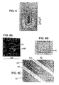
- the first type of electrochemical cell is a 200 ⁇ L well containing three thin golden film electrodes printed in a circular area of 6 mm diameter, Figure 5 .
- the platform is a phenolic resin that is commonly used as a substrate for copper printed circuits on board (PCB).
- these electrodes are obtained by classical printed circuit on board (PCB) realization techniques.
- PCB printed circuit on board
- the copper layer is first etched in the form of a shadow mask for the actual electrode design.
- the electrode realization is performed with the deposition of a 10 nm titanium layer forming an adherence layer and a 100 nm gold layer obtained by e-beam evaporations. After the e-beam evaporation, the copper mask layer is removed using ferric chloride. All materials and chemicals for PCB realization are purchased from RS components.
- the reference electrode 50 is obtained by applying a small spot 52 of solid Ag/AgCl amalgam (Dupont 5874 Silver/Silver Chloride Composition). This solid Ag/AgCl reference electrode has been checked for its stability, repeatability and reliability in different measurement setups from pH 2 to 12. This reference displays an electrode potential 100 mV higher ( ⁇ 300 mV vs. SHE) than a commercial reference electrode ( ⁇ 197 mV vs. SHE).
- the polyaniline layer on the working electrode 54 can be obtained by cyclic voltametry or by constant current application.
- the polyaniline working electrode 54 represented in Figure 5 was obtained by applying 1.5 ⁇ A during 10 minutes in an aqueous solution of 0.2M aniline and 2M HCl using the presented smart sensor architecture.
- the counter electrode 56 is localized between the working electrode 54 and the reference electrode 50.
- the second type of electrochemical cell is a 40 ⁇ L well containing nine sets of platinum micrometric interdigitated electrodes shown in Figures 6A, 6B and 6C .
- the central set is short-circuited by a small spot 61 of solid Ag/AgCl amalgam (Dupont 5874 Silver/Silver Chloride Composition). This set has been checked as well for its stability and repeatability as a reference electrode in different measurement setups from pH 2 to 12.
- the eight remaining sets are used as couples of counter- and working electrodes.
- the counter electrodes 63 are connected together so that the system contains only one common reference, one common counter and eight individual working electrodes 65.
- platinum electrodes (5 nm Ti, 100 nm Pt) are produced by evaporation and usual photolithography techniques on a 100 nm thick SiO2 layer obtained by dry oxidation of a 360 ⁇ m thick silicon substrate.
- the 6 ⁇ m wide electrodes (2*21 digits) are spaced by 6 ⁇ m and interdigitated over a square surface of 500*500 ⁇ m 2 .
- the electrical tracks are insulated from the liquid by means of a 500 nm thick layer of silicon nitride visible in Figures 6A and 6B . This layer is obtained by plasma enhanced chemical vapor deposition at 250°C.
- the polyaniline layer on the interdigitated working electrodes can be obtained by cyclic voltametry or by constant current application.
- the polyaniline working electrode visible on Figures 6B and 6C is obtained by applying 0.15 ⁇ A during 5 minutes in an aqueous solution of 0.2M aniline and 2M HCl using the presented system.
- the different pH buffer solutions for pH sensing were obtained using FIXANAL recipes from the Riedel de Haen Company.
- the conductivity of all these solutions was adjusted at 11 mS using KCI solutions and a Hanna HI255 conductivity meter.
- Aniline was distilled twice under argon reduced pressure before use.
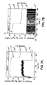
- Figure 7B is a magnification of Period B, C and of the measured current.
- the curve 71 shows the input potential with its scale on the left side and curve 73 shows the output current with its scale on the right side.
- polyaniline is electrosynthesized, using the algorithm shown in Figure 4 , maintaining the current of the output signal at a target of 1.5 ⁇ A and using a 10 kOhms load resistor in the multiplexer 19. Electrosynthesis occurs at a potential of ⁇ 0.75 volts vs. the solid Ag/AgCl reference.
- period B After 10 minutes of polyaniline electrosynthesis, period B begins, the load resistor is switched to infinite and the target is set to zero.
- the PAN I working electrode equilibrium potential in its synthesis solution is found at ⁇ 0.7 Volts.
- the synthesis solution is replaced by a buffer solution at pH 4.
- the polyaniline working electrode equilibrium potential reaches ⁇ 0.37 Volts, indicating the proper functioning of the device as a pH sensor.
- the current curve in Figure 7B clearly illustrates the potentiostat acting as a discrete voltage comparator: as the chosen resistor is infinite, the current passing through the working electrode is limited to the operational amplifier intrinsic current leak. For this reason, the current curved displayed in Figure 7B is the output of the current to voltage converter (i.e. -5V to 5V) scaled with the operational amplifier intrinsic current leak manufacturer specification ( ⁇ 10 pA). It is interesting to note that this type of signal could directly be used as a binary coded signal for data size reduction. Indeed, as the algorithm is known the potential curve can be reconstructed using this discrete current signal with a simple digital operation.
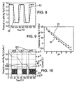
- Figure 8 illustrates the difference in the measured potential signals 81 and 83 using the algorithms proposed in Figures 3 and 4 , respectively.
- the two curves have been obtained by successively switching the buffer solution between pH 4 ( ⁇ 0.36 V) and pH 10 ( ⁇ -0.1V) with an algorithm iteration every 100 ms, an infinite load resistor and a null target output current.
- the array of micrometric interdigitated electrodes has then been considered.
- the proximity of the counter electrode to each of the eight working electrodes and their micrometric scale has intuitively been chosen for the confinement of electrical currents into very small separated volumes of the same sample.
- classical potentiometry measurements as a function of the pH, using only the working and the solid reference electrodes have been found difficult to reproduce.
- the proximity and reduced size of these electrodes is responsible for a constant discharge of the electrochemical cell: the difference in potential between the working and reference electrode tends to cancel as observed in Figure 10 using the system disclosed here above and one set of micrometric interdigitated electrodes as in Figure 6A .
- the current signal rapid oscillations clearly indicate the quasi-equilibrium periods.
- the current exchanges are deliberately restricted by using an infinite resistor in the current to voltage converter 15 in order to limit redox alterations of the polyaniline.
- the current exchanges are allowed and measured by using a 1 MOhm resistor in the current to voltage converter 15.
- the potential 130 alternates every 200 ms (iteration period) with a chosen amplitude of 6 mV around the equilibrium potential as a consequence of the algorithm.
- These square wave low voltage alternations induce successive current relaxations 131.
- These current relaxation curves 131 are direct indications of electrochemical processes taking place at the working electrode surface (electrochemical impedance, redox processes, etc).
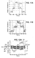
- Figure 13 shows a variant of realization using a ⁇ -lactamase enzyme as a sensitizer.
- ⁇ -lactamase enzymes can hydrolyze ⁇ -lactam based antibiotics, such as penicillin-G, to lead to a global pH decrease.
- the experiment starts from eight pristine working electrodes.
- Electro-synthesis occurs at a potential of about 0.75 volts vs. the solid Ag/AgCl reference.
- the load resistor is switched to infinite and the target current is set to zero for all electrodes.
- the PANI working electrodes equilibrium potentials in their synthesis solution decrease.
- period C three successive detections 141, 142 and 143 of penicillin G at a 1 mM concentration are done.
- the four sensitized electrodes display an abrupt response 144 to penicillin, from pH ⁇ 7 to pH ⁇ 5, while the other electrodes electrochemical potentials 145 only slowly increase as a consequence of protons diffusion from the sensitized electrodes.
- the method may be implemented by a computer program product that is able to implement any of the method steps as described above when loaded and run on computer means.
- the computer program may be stored/distributed on a suitable medium supplied together with or as a part of other hardware, but may also be distributed in other forms, such as via the Internet or other wired or wireless telecommunication systems.
- An integrated circuit may be arranged to perform any of the method steps in accordance with the disclosed embodiments.
Landscapes
- Chemical & Material Sciences (AREA)
- Life Sciences & Earth Sciences (AREA)
- Health & Medical Sciences (AREA)
- Physics & Mathematics (AREA)
- Chemical Kinetics & Catalysis (AREA)
- Electrochemistry (AREA)
- Molecular Biology (AREA)
- Analytical Chemistry (AREA)
- Biochemistry (AREA)
- General Health & Medical Sciences (AREA)
- General Physics & Mathematics (AREA)
- Immunology (AREA)
- Pathology (AREA)
- Investigating Or Analyzing Materials By The Use Of Electric Means (AREA)
Claims (10)
- System zum Messen eines Lösungs-pH-Werts, umfassend:• einen Potentiostat (1), wobei der Potentiostat eine Arbeitselektrode (W) umfasst, die aus einem elektrisch leitenden Festpolymer-Wandler hergestellt ist, einen Eingang (9), um ein Eingangssignal zu empfangen, das das Potential angibt, das zwischen der Arbeitselektrode und einer Referenzelektrode (R) des Potentiostats angewendet werden muss, und einen Ausgang (17), um ein Ausgangssignal zu übertragen, das die Größe des Stroms angibt, der zwischen einer Gegenelektrode (C) des Potentiostats und der Arbeitselektrode fließt, wobei die drei Elektroden in die Lösung getaucht sind;• einen digitalen Prozessor (23), der mit einem Digital-Analog-Umformer (25) verbunden ist, um das Eingangssignal zu erzeugen; und mit einem Analog-Digital-Umformer (27), um einen digitalen Wert zu empfangen, der das Ausgangssignal darstellt;dadurch gekennzeichnet, dass der digitale Prozessor ausgelegt ist, um das Eingangssignal zu modifizieren, um das Ausgangssignals innerhalb eines vorbestimmten Bereichs zu halten, so dass das Eingangssignal-Potential den Lösungs-pH-Wert darstellt, wenn sich das Ausgangssignal innerhalb des vorbestimmten Bereichs befindet.
- System nach Anspruch 1, wobei die Arbeitselektrode aus Polyanilin oder Polypyrrol hergestellt ist.
- System nach Anspruch 1 oder 2, wobei der vorbestimmte Bereich auf Null zentriert ist.
- System nach Anspruch 3, wobei der Potentiostat einen Operationsverstärker mit einem Eingang umfasst, der mit der Arbeitselektrode verbunden ist, wobei der Ausgang des Operationsverstärkers das Ausgangssignal erzeugt und der Operationsverstärker parallel mit einem Widerstand montiert ist, um als Strom-Spannungs-Umformer zu dienen, der durch den Widerstand skaliert ist, wobei der Widerstand hoch oder unendlich ist, um den Strom durch Sättigung des Operationsverstärkers zu begrenzen.
- System nach Anspruch 4, wobei der Widerstand in einem Bereich modifiziert ist, der die Sättigung des Operationsverstärkers verhindert, und der vorbestimmte Bereich des Ausgangssignals außerhalb von Null liegt, so dass der Redoxzustand des elektrisch leitfähigen Festpolymer-Wandlers durch einen Stromfluss modifiziert ist.
- System nach Anspruch 4, wobei der Widerstand in einem Bereich modifiziert ist, der die Sättigung des Operationsverstärkers verhindert, so dass das Ausgangssignal innerhalb des vorbestimmten Bereichs oszilliert, wobei die Amplitude und die Phase der Oszillierungen die elektrochemische Impedanz der elektrochemischen Zelle anzeigt.
- System zum Messen von biologischen Molekülen, umfassend ein System nach einem der Ansprüche 1 bis 6, wobei der elektrisch leitfähige Festpolymer-Wandler durch einen Proton-abgebenden Enzymmediator sensibilisiert ist.
- System zum Messen von biologischen Molekülen nach Anspruch 7, wobei der Proton-abgebende Enzymmediator ein β-Lactamase-Enzym umfasst.
- Verfahren zum Messen eines Lösungs-pH-Werts mit einem Potentiostat, wobei der Potentiostat eine Arbeitselektrode umfasst, die aus einem elektrisch leitenden Festpolymer-Wandler hergestellt ist, einen Eingang, um ein Eingangssignal zu empfangen, das das Potential angibt, das zwischen der Arbeitselektrode und einer Referenzelektrode des Potentiostats angewendet werden muss, und einen Ausgang, um ein Ausgangssignal zu übertragen, das die Größe des Stroms angibt, der zwischen einer Gegenelektrode des Potentiostats und der Arbeitselektrode fließt, wobei die drei Elektroden in die Lösung getaucht sind, wobei das Verfahren Folgendes umfasst:• Erzeugen (31, 41) des Eingangssignals;• Messen (33, 43) des Ausgangssignals;• Modifizieren (35, 45) des Eingangssignals, um das Ausgangssignal innerhalb eines vorbestimmten Bereichs zu halten, so dass das Eingangssignal-Potenzial den Lösungs-pH-Wert darstellt, wenn sich das Ausgangssignal innerhalb des vorbestimmten Bereichs befindet.
- Computersoftwareprodukt, das in einem Aufzeichnungsmedium gespeichert ist und einen Satz von Anweisungen umfasst, um einem Computer zu ermöglichen, das Verfahren nach Anspruch 9 anzuwenden, wenn der Computer den Satz von Anweisungen ausführt.
Priority Applications (1)
| Application Number | Priority Date | Filing Date | Title |
|---|---|---|---|
| EP10724737.1A EP2521908B1 (de) | 2010-01-07 | 2010-06-02 | Intelligentes sensorsystem mit einem elektroaktiven polymer |
Applications Claiming Priority (3)
| Application Number | Priority Date | Filing Date | Title |
|---|---|---|---|
| EP10150280A EP2345892A1 (de) | 2010-01-07 | 2010-01-07 | Intelligentes Sensorsystem mit einem elektroaktiven Polymer |
| EP10724737.1A EP2521908B1 (de) | 2010-01-07 | 2010-06-02 | Intelligentes sensorsystem mit einem elektroaktiven polymer |
| PCT/EP2010/057753 WO2011082837A1 (en) | 2010-01-07 | 2010-06-02 | Smart sensor system using an electroactive polymer |
Publications (2)
| Publication Number | Publication Date |
|---|---|
| EP2521908A1 EP2521908A1 (de) | 2012-11-14 |
| EP2521908B1 true EP2521908B1 (de) | 2015-08-26 |
Family
ID=42124318
Family Applications (2)
| Application Number | Title | Priority Date | Filing Date |
|---|---|---|---|
| EP10150280A Withdrawn EP2345892A1 (de) | 2010-01-07 | 2010-01-07 | Intelligentes Sensorsystem mit einem elektroaktiven Polymer |
| EP10724737.1A Not-in-force EP2521908B1 (de) | 2010-01-07 | 2010-06-02 | Intelligentes sensorsystem mit einem elektroaktiven polymer |
Family Applications Before (1)
| Application Number | Title | Priority Date | Filing Date |
|---|---|---|---|
| EP10150280A Withdrawn EP2345892A1 (de) | 2010-01-07 | 2010-01-07 | Intelligentes Sensorsystem mit einem elektroaktiven Polymer |
Country Status (4)
| Country | Link |
|---|---|
| US (1) | US8877036B2 (de) |
| EP (2) | EP2345892A1 (de) |
| ES (1) | ES2554710T3 (de) |
| WO (1) | WO2011082837A1 (de) |
Families Citing this family (11)
| Publication number | Priority date | Publication date | Assignee | Title |
|---|---|---|---|---|
| US12345680B1 (en) | 2014-03-13 | 2025-07-01 | Innosense Corporation | Modular chemiresistive sensor for real-time ethylene monitoring |
| US9896772B2 (en) | 2014-03-13 | 2018-02-20 | Innosense Llc | Modular chemiresistive sensor |
| WO2015193501A1 (en) * | 2014-06-19 | 2015-12-23 | Université Catholique de Louvain | Method for detecting enzyme activity hydrolyzing beta-lactam ring antimicrobial agents |
| CZ2014672A3 (cs) * | 2014-09-30 | 2015-08-12 | Vysoké Učení Technické V Brně | Potenciostat |
| US20180045675A1 (en) * | 2015-02-25 | 2018-02-15 | The Regents Of The University Of California | Single-cell intracellular nano-ph probes |
| US11867660B2 (en) * | 2015-07-06 | 2024-01-09 | Robert Bosch Gmbh | Electronic control of the pH of a solution close to an electrode surface |
| WO2020245312A1 (en) | 2019-06-05 | 2020-12-10 | CSEM Centre Suisse d'Electronique et de Microtechnique SA - Recherche et Développement | A ph measuring device comprising a cnc-pani based composite compound and corresponding methods |
| CN111579627B (zh) * | 2020-05-29 | 2023-09-08 | 山东师范大学 | 一种肿瘤多生物标志物并行检测系统及方法 |
| WO2022119546A2 (en) * | 2020-12-03 | 2022-06-09 | Ege Universitesi | A miniaturized compact electrochemical analyzer |
| CN114441614A (zh) * | 2021-12-30 | 2022-05-06 | 广州市赛特检测有限公司 | 一种电化学微生物快速检测仪及生物探针的修饰方法 |
| WO2025163279A1 (en) * | 2024-01-29 | 2025-08-07 | Cirrus Logic International Semiconductor Limited | Circuitry for measurement of electrochemical cells |
Family Cites Families (2)
| Publication number | Priority date | Publication date | Assignee | Title |
|---|---|---|---|---|
| DE10062062C1 (de) * | 2000-12-13 | 2002-02-28 | Draegerwerk Ag | Elektrochemischer Sensor |
| JP4567333B2 (ja) * | 2001-08-24 | 2010-10-20 | センサーテック・リミテッド | 高感度電位差測定センサを製造する方法 |
-
2010
- 2010-01-07 EP EP10150280A patent/EP2345892A1/de not_active Withdrawn
- 2010-06-02 US US13/520,074 patent/US8877036B2/en not_active Expired - Fee Related
- 2010-06-02 EP EP10724737.1A patent/EP2521908B1/de not_active Not-in-force
- 2010-06-02 ES ES10724737.1T patent/ES2554710T3/es active Active
- 2010-06-02 WO PCT/EP2010/057753 patent/WO2011082837A1/en not_active Ceased
Also Published As
| Publication number | Publication date |
|---|---|
| US20120298530A1 (en) | 2012-11-29 |
| EP2345892A1 (de) | 2011-07-20 |
| EP2521908A1 (de) | 2012-11-14 |
| US8877036B2 (en) | 2014-11-04 |
| ES2554710T3 (es) | 2015-12-22 |
| WO2011082837A1 (en) | 2011-07-14 |
Similar Documents
| Publication | Publication Date | Title |
|---|---|---|
| EP2521908B1 (de) | Intelligentes sensorsystem mit einem elektroaktiven polymer | |
| US9164054B2 (en) | Method and apparatus for assay of electrochemical properties | |
| Guzinski et al. | Equilibration time of solid contact ion-selective electrodes | |
| CN101595381B (zh) | 电化学测定用电极板、具有该电极板的电化学测定装置、和使用该电极板对目标物质进行定量的方法 | |
| Brett et al. | Electrochemical sensing in solution—origins, applications and future perspectives | |
| Lakard et al. | Miniaturized pH biosensors based on electrochemically modified electrodes with biocompatible polymers | |
| US9279781B2 (en) | Measuring arrangement and method for registering an analyte concentration in a measured medium | |
| US11313781B2 (en) | Self-parative calibration method of an aptamer sensor | |
| Kongkaew et al. | Studying the preparation, electrochemical performance testing, comparison and application of a cost-effective flexible graphene working electrode | |
| CN111108374A (zh) | PH传感器和用于pH传感器的校准方法 | |
| Zine et al. | Hydrogen-selective microelectrodes based on silicon needles | |
| Saban et al. | Multi-element heavy metal ion sensors for aqueous solutions | |
| Yamada et al. | All‐solid‐state Fluoride Ion‐selective Electrode using LaF3 Single Crystal with Poly (3, 4‐ethylenedioxythiophene) as Solid Contact Layer | |
| Yunus et al. | A method to probe electrochemically active material state in portable sensor applications | |
| Hussien et al. | Highly-stable miniaturized Pt-nanostructures/Pt coated wire ion selective electrode for fluoxetine HCl | |
| Sakly et al. | Platinum electrode functionalized with calix [4] arene thin films for impedimetric detection of sodium ions | |
| CN116500110B (zh) | 一种全固态离子选择电极免仪器标准电位校准方法 | |
| Herdman et al. | The aqueous deposition of a pH sensitive quinone on carbon paste electrodes using linear sweep voltammetry | |
| Andrews et al. | Fabrication and sensing applications of microelectrodes on silicon substrates | |
| Song et al. | An on-chip chemiresistive polyaniline nanowire-based pH sensor with self-calibration capability | |
| Muztahidul et al. | Development of electric-field control membrane coated striped-electrode type potassium ion sensor for drift-free in continuous and long-term potassium ion monitoring | |
| Zou et al. | Improved design of electronic tongue integrated MEA with MLAPS for environmental monitoring | |
| Recasens | 3.4 Characterisation | |
| AU2012204094A1 (en) | Method and apparatus for assay of electrochemical properties |
Legal Events
| Date | Code | Title | Description |
|---|---|---|---|
| PUAI | Public reference made under article 153(3) epc to a published international application that has entered the european phase |
Free format text: ORIGINAL CODE: 0009012 |
|
| 17P | Request for examination filed |
Effective date: 20120628 |
|
| AK | Designated contracting states |
Kind code of ref document: A1 Designated state(s): AL AT BE BG CH CY CZ DE DK EE ES FI FR GB GR HR HU IE IS IT LI LT LU LV MC MK MT NL NO PL PT RO SE SI SK SM TR |
|
| DAX | Request for extension of the european patent (deleted) | ||
| GRAP | Despatch of communication of intention to grant a patent |
Free format text: ORIGINAL CODE: EPIDOSNIGR1 |
|
| INTG | Intention to grant announced |
Effective date: 20150320 |
|
| GRAS | Grant fee paid |
Free format text: ORIGINAL CODE: EPIDOSNIGR3 |
|
| GRAA | (expected) grant |
Free format text: ORIGINAL CODE: 0009210 |
|
| AK | Designated contracting states |
Kind code of ref document: B1 Designated state(s): AL AT BE BG CH CY CZ DE DK EE ES FI FR GB GR HR HU IE IS IT LI LT LU LV MC MK MT NL NO PL PT RO SE SI SK SM TR |
|
| REG | Reference to a national code |
Ref country code: GB Ref legal event code: FG4D |
|
| REG | Reference to a national code |
Ref country code: CH Ref legal event code: EP |
|
| REG | Reference to a national code |
Ref country code: AT Ref legal event code: REF Ref document number: 745481 Country of ref document: AT Kind code of ref document: T Effective date: 20150915 |
|
| REG | Reference to a national code |
Ref country code: IE Ref legal event code: FG4D |
|
| REG | Reference to a national code |
Ref country code: DE Ref legal event code: R096 Ref document number: 602010026982 Country of ref document: DE |
|
| REG | Reference to a national code |
Ref country code: ES Ref legal event code: FG2A Ref document number: 2554710 Country of ref document: ES Kind code of ref document: T3 Effective date: 20151222 |
|
| REG | Reference to a national code |
Ref country code: AT Ref legal event code: MK05 Ref document number: 745481 Country of ref document: AT Kind code of ref document: T Effective date: 20150826 |
|
| REG | Reference to a national code |
Ref country code: LT Ref legal event code: MG4D |
|
| PG25 | Lapsed in a contracting state [announced via postgrant information from national office to epo] |
Ref country code: LT Free format text: LAPSE BECAUSE OF FAILURE TO SUBMIT A TRANSLATION OF THE DESCRIPTION OR TO PAY THE FEE WITHIN THE PRESCRIBED TIME-LIMIT Effective date: 20150826 Ref country code: NO Free format text: LAPSE BECAUSE OF FAILURE TO SUBMIT A TRANSLATION OF THE DESCRIPTION OR TO PAY THE FEE WITHIN THE PRESCRIBED TIME-LIMIT Effective date: 20151126 Ref country code: FI Free format text: LAPSE BECAUSE OF FAILURE TO SUBMIT A TRANSLATION OF THE DESCRIPTION OR TO PAY THE FEE WITHIN THE PRESCRIBED TIME-LIMIT Effective date: 20150826 Ref country code: GR Free format text: LAPSE BECAUSE OF FAILURE TO SUBMIT A TRANSLATION OF THE DESCRIPTION OR TO PAY THE FEE WITHIN THE PRESCRIBED TIME-LIMIT Effective date: 20151127 Ref country code: LV Free format text: LAPSE BECAUSE OF FAILURE TO SUBMIT A TRANSLATION OF THE DESCRIPTION OR TO PAY THE FEE WITHIN THE PRESCRIBED TIME-LIMIT Effective date: 20150826 |
|
| REG | Reference to a national code |
Ref country code: NL Ref legal event code: FP |
|
| PG25 | Lapsed in a contracting state [announced via postgrant information from national office to epo] |
Ref country code: AT Free format text: LAPSE BECAUSE OF FAILURE TO SUBMIT A TRANSLATION OF THE DESCRIPTION OR TO PAY THE FEE WITHIN THE PRESCRIBED TIME-LIMIT Effective date: 20150826 Ref country code: PL Free format text: LAPSE BECAUSE OF FAILURE TO SUBMIT A TRANSLATION OF THE DESCRIPTION OR TO PAY THE FEE WITHIN THE PRESCRIBED TIME-LIMIT Effective date: 20150826 Ref country code: PT Free format text: LAPSE BECAUSE OF FAILURE TO SUBMIT A TRANSLATION OF THE DESCRIPTION OR TO PAY THE FEE WITHIN THE PRESCRIBED TIME-LIMIT Effective date: 20151228 Ref country code: HR Free format text: LAPSE BECAUSE OF FAILURE TO SUBMIT A TRANSLATION OF THE DESCRIPTION OR TO PAY THE FEE WITHIN THE PRESCRIBED TIME-LIMIT Effective date: 20150826 Ref country code: IS Free format text: LAPSE BECAUSE OF FAILURE TO SUBMIT A TRANSLATION OF THE DESCRIPTION OR TO PAY THE FEE WITHIN THE PRESCRIBED TIME-LIMIT Effective date: 20151226 Ref country code: SE Free format text: LAPSE BECAUSE OF FAILURE TO SUBMIT A TRANSLATION OF THE DESCRIPTION OR TO PAY THE FEE WITHIN THE PRESCRIBED TIME-LIMIT Effective date: 20150826 |
|
| PG25 | Lapsed in a contracting state [announced via postgrant information from national office to epo] |
Ref country code: CZ Free format text: LAPSE BECAUSE OF FAILURE TO SUBMIT A TRANSLATION OF THE DESCRIPTION OR TO PAY THE FEE WITHIN THE PRESCRIBED TIME-LIMIT Effective date: 20150826 Ref country code: EE Free format text: LAPSE BECAUSE OF FAILURE TO SUBMIT A TRANSLATION OF THE DESCRIPTION OR TO PAY THE FEE WITHIN THE PRESCRIBED TIME-LIMIT Effective date: 20150826 Ref country code: SK Free format text: LAPSE BECAUSE OF FAILURE TO SUBMIT A TRANSLATION OF THE DESCRIPTION OR TO PAY THE FEE WITHIN THE PRESCRIBED TIME-LIMIT Effective date: 20150826 Ref country code: DK Free format text: LAPSE BECAUSE OF FAILURE TO SUBMIT A TRANSLATION OF THE DESCRIPTION OR TO PAY THE FEE WITHIN THE PRESCRIBED TIME-LIMIT Effective date: 20150826 |
|
| REG | Reference to a national code |
Ref country code: DE Ref legal event code: R082 Ref document number: 602010026982 Country of ref document: DE Representative=s name: HERNANDEZ, YORCK, DIPL.-ING., DE |
|
| REG | Reference to a national code |
Ref country code: DE Ref legal event code: R097 Ref document number: 602010026982 Country of ref document: DE |
|
| PG25 | Lapsed in a contracting state [announced via postgrant information from national office to epo] |
Ref country code: RO Free format text: LAPSE BECAUSE OF FAILURE TO SUBMIT A TRANSLATION OF THE DESCRIPTION OR TO PAY THE FEE WITHIN THE PRESCRIBED TIME-LIMIT Effective date: 20150826 |
|
| REG | Reference to a national code |
Ref country code: FR Ref legal event code: PLFP Year of fee payment: 7 |
|
| PLBE | No opposition filed within time limit |
Free format text: ORIGINAL CODE: 0009261 |
|
| STAA | Information on the status of an ep patent application or granted ep patent |
Free format text: STATUS: NO OPPOSITION FILED WITHIN TIME LIMIT |
|
| 26N | No opposition filed |
Effective date: 20160530 |
|
| PG25 | Lapsed in a contracting state [announced via postgrant information from national office to epo] |
Ref country code: SI Free format text: LAPSE BECAUSE OF FAILURE TO SUBMIT A TRANSLATION OF THE DESCRIPTION OR TO PAY THE FEE WITHIN THE PRESCRIBED TIME-LIMIT Effective date: 20150826 |
|
| PG25 | Lapsed in a contracting state [announced via postgrant information from national office to epo] |
Ref country code: MC Free format text: LAPSE BECAUSE OF FAILURE TO SUBMIT A TRANSLATION OF THE DESCRIPTION OR TO PAY THE FEE WITHIN THE PRESCRIBED TIME-LIMIT Effective date: 20150826 |
|
| REG | Reference to a national code |
Ref country code: CH Ref legal event code: PL |
|
| REG | Reference to a national code |
Ref country code: NL Ref legal event code: MM Effective date: 20160701 |
|
| REG | Reference to a national code |
Ref country code: IE Ref legal event code: MM4A |
|
| PG25 | Lapsed in a contracting state [announced via postgrant information from national office to epo] |
Ref country code: LI Free format text: LAPSE BECAUSE OF NON-PAYMENT OF DUE FEES Effective date: 20160630 Ref country code: CH Free format text: LAPSE BECAUSE OF NON-PAYMENT OF DUE FEES Effective date: 20160630 |
|
| PG25 | Lapsed in a contracting state [announced via postgrant information from national office to epo] |
Ref country code: IE Free format text: LAPSE BECAUSE OF NON-PAYMENT OF DUE FEES Effective date: 20160602 Ref country code: NL Free format text: LAPSE BECAUSE OF NON-PAYMENT OF DUE FEES Effective date: 20160701 |
|
| REG | Reference to a national code |
Ref country code: FR Ref legal event code: PLFP Year of fee payment: 8 |
|
| PG25 | Lapsed in a contracting state [announced via postgrant information from national office to epo] |
Ref country code: SM Free format text: LAPSE BECAUSE OF FAILURE TO SUBMIT A TRANSLATION OF THE DESCRIPTION OR TO PAY THE FEE WITHIN THE PRESCRIBED TIME-LIMIT Effective date: 20150826 Ref country code: CY Free format text: LAPSE BECAUSE OF FAILURE TO SUBMIT A TRANSLATION OF THE DESCRIPTION OR TO PAY THE FEE WITHIN THE PRESCRIBED TIME-LIMIT Effective date: 20150826 Ref country code: HU Free format text: LAPSE BECAUSE OF FAILURE TO SUBMIT A TRANSLATION OF THE DESCRIPTION OR TO PAY THE FEE WITHIN THE PRESCRIBED TIME-LIMIT; INVALID AB INITIO Effective date: 20100602 |
|
| REG | Reference to a national code |
Ref country code: FR Ref legal event code: PLFP Year of fee payment: 9 |
|
| PG25 | Lapsed in a contracting state [announced via postgrant information from national office to epo] |
Ref country code: LU Free format text: LAPSE BECAUSE OF NON-PAYMENT OF DUE FEES Effective date: 20160602 Ref country code: MK Free format text: LAPSE BECAUSE OF FAILURE TO SUBMIT A TRANSLATION OF THE DESCRIPTION OR TO PAY THE FEE WITHIN THE PRESCRIBED TIME-LIMIT Effective date: 20150826 Ref country code: MT Free format text: LAPSE BECAUSE OF NON-PAYMENT OF DUE FEES Effective date: 20160630 Ref country code: TR Free format text: LAPSE BECAUSE OF FAILURE TO SUBMIT A TRANSLATION OF THE DESCRIPTION OR TO PAY THE FEE WITHIN THE PRESCRIBED TIME-LIMIT Effective date: 20150826 |
|
| PG25 | Lapsed in a contracting state [announced via postgrant information from national office to epo] |
Ref country code: BG Free format text: LAPSE BECAUSE OF FAILURE TO SUBMIT A TRANSLATION OF THE DESCRIPTION OR TO PAY THE FEE WITHIN THE PRESCRIBED TIME-LIMIT Effective date: 20150826 |
|
| PG25 | Lapsed in a contracting state [announced via postgrant information from national office to epo] |
Ref country code: AL Free format text: LAPSE BECAUSE OF FAILURE TO SUBMIT A TRANSLATION OF THE DESCRIPTION OR TO PAY THE FEE WITHIN THE PRESCRIBED TIME-LIMIT Effective date: 20150826 |
|
| PGFP | Annual fee paid to national office [announced via postgrant information from national office to epo] |
Ref country code: FR Payment date: 20200619 Year of fee payment: 11 Ref country code: DE Payment date: 20200618 Year of fee payment: 11 |
|
| PGFP | Annual fee paid to national office [announced via postgrant information from national office to epo] |
Ref country code: GB Payment date: 20200625 Year of fee payment: 11 Ref country code: BE Payment date: 20200625 Year of fee payment: 11 |
|
| PGFP | Annual fee paid to national office [announced via postgrant information from national office to epo] |
Ref country code: ES Payment date: 20200825 Year of fee payment: 11 |
|
| PGFP | Annual fee paid to national office [announced via postgrant information from national office to epo] |
Ref country code: IT Payment date: 20200625 Year of fee payment: 11 |
|
| REG | Reference to a national code |
Ref country code: DE Ref legal event code: R119 Ref document number: 602010026982 Country of ref document: DE |
|
| GBPC | Gb: european patent ceased through non-payment of renewal fee |
Effective date: 20210602 |
|
| REG | Reference to a national code |
Ref country code: BE Ref legal event code: MM Effective date: 20210630 |
|
| PG25 | Lapsed in a contracting state [announced via postgrant information from national office to epo] |
Ref country code: GB Free format text: LAPSE BECAUSE OF NON-PAYMENT OF DUE FEES Effective date: 20210602 Ref country code: DE Free format text: LAPSE BECAUSE OF NON-PAYMENT OF DUE FEES Effective date: 20220101 |
|
| PG25 | Lapsed in a contracting state [announced via postgrant information from national office to epo] |
Ref country code: FR Free format text: LAPSE BECAUSE OF NON-PAYMENT OF DUE FEES Effective date: 20210630 |
|
| PG25 | Lapsed in a contracting state [announced via postgrant information from national office to epo] |
Ref country code: IT Free format text: LAPSE BECAUSE OF NON-PAYMENT OF DUE FEES Effective date: 20210602 Ref country code: BE Free format text: LAPSE BECAUSE OF NON-PAYMENT OF DUE FEES Effective date: 20210630 |
|
| REG | Reference to a national code |
Ref country code: ES Ref legal event code: FD2A Effective date: 20220826 |
|
| PG25 | Lapsed in a contracting state [announced via postgrant information from national office to epo] |
Ref country code: ES Free format text: LAPSE BECAUSE OF NON-PAYMENT OF DUE FEES Effective date: 20210603 |