EP2521379A1 - Hearing aid - Google Patents
Hearing aid Download PDFInfo
- Publication number
- EP2521379A1 EP2521379A1 EP12726568A EP12726568A EP2521379A1 EP 2521379 A1 EP2521379 A1 EP 2521379A1 EP 12726568 A EP12726568 A EP 12726568A EP 12726568 A EP12726568 A EP 12726568A EP 2521379 A1 EP2521379 A1 EP 2521379A1
- Authority
- EP
- European Patent Office
- Prior art keywords
- hearing aid
- arc
- engaging component
- arc part
- earpiece
- Prior art date
- Legal status (The legal status is an assumption and is not a legal conclusion. Google has not performed a legal analysis and makes no representation as to the accuracy of the status listed.)
- Withdrawn
Links
Images


Classifications
-
- H—ELECTRICITY
- H04—ELECTRIC COMMUNICATION TECHNIQUE
- H04R—LOUDSPEAKERS, MICROPHONES, GRAMOPHONE PICK-UPS OR LIKE ACOUSTIC ELECTROMECHANICAL TRANSDUCERS; DEAF-AID SETS; PUBLIC ADDRESS SYSTEMS
- H04R25/00—Deaf-aid sets, i.e. electro-acoustic or electro-mechanical hearing aids; Electric tinnitus maskers providing an auditory perception
- H04R25/65—Housing parts, e.g. shells, tips or moulds, or their manufacture
- H04R25/652—Ear tips; Ear moulds
-
- H—ELECTRICITY
- H04—ELECTRIC COMMUNICATION TECHNIQUE
- H04R—LOUDSPEAKERS, MICROPHONES, GRAMOPHONE PICK-UPS OR LIKE ACOUSTIC ELECTROMECHANICAL TRANSDUCERS; DEAF-AID SETS; PUBLIC ADDRESS SYSTEMS
- H04R2225/00—Details of deaf aids covered by H04R25/00, not provided for in any of its subgroups
- H04R2225/021—Behind the ear [BTE] hearing aids
- H04R2225/0213—Constructional details of earhooks, e.g. shape, material
-
- H—ELECTRICITY
- H04—ELECTRIC COMMUNICATION TECHNIQUE
- H04R—LOUDSPEAKERS, MICROPHONES, GRAMOPHONE PICK-UPS OR LIKE ACOUSTIC ELECTROMECHANICAL TRANSDUCERS; DEAF-AID SETS; PUBLIC ADDRESS SYSTEMS
- H04R25/00—Deaf-aid sets, i.e. electro-acoustic or electro-mechanical hearing aids; Electric tinnitus maskers providing an auditory perception
- H04R25/60—Mounting or interconnection of hearing aid parts, e.g. inside tips, housings or to ossicles
- H04R25/607—Mounting or interconnection of hearing aid parts, e.g. inside tips, housings or to ossicles of earhooks
-
- H—ELECTRICITY
- H04—ELECTRIC COMMUNICATION TECHNIQUE
- H04R—LOUDSPEAKERS, MICROPHONES, GRAMOPHONE PICK-UPS OR LIKE ACOUSTIC ELECTROMECHANICAL TRANSDUCERS; DEAF-AID SETS; PUBLIC ADDRESS SYSTEMS
- H04R25/00—Deaf-aid sets, i.e. electro-acoustic or electro-mechanical hearing aids; Electric tinnitus maskers providing an auditory perception
- H04R25/65—Housing parts, e.g. shells, tips or moulds, or their manufacture
- H04R25/658—Manufacture of housing parts
Definitions
- the present invention relates to a behind-the-ear type of hearing aid.
- a conventional hearing aid of this type comprises a body case that is worn behind an ear, and a string-shaped sound conductor that is linked at one end to this body case and at the other end to an earpiece, and there is a known example in which a string-shaped engaging part that engages with the antitragus of the ear is attached to the other end of the sound conductor (see Patent Literature 1, for example).
- the body case is worn behind an ear, and the earpiece is inserted into the external auditory canal, after which the engaging part is engaged with the antitragus of the ear, which keeps the earpiece from coming out of the external auditory canal.
- the string-shaped engaging part is designed to be longer because the size of an ear varies with the individual wearing the hearing aid. Therefore, when a person with small ears wears the hearing aid, the distal end side of the engaging part is cut off with scissors or another such cutting tool to adjust the length. In other words, the engaging part has to be cut with the above-mentioned cutting tool in order to match it to the size of the ear of the individual wearing the hearing aid, and this made the fitting of the hearing aid more difficult.
- a ring-shaped engaging part that engages with the tragus be attached to the other end of the sound conductor of the hearing aid (see Patent Literature 2, for example).
- this hearing aid one end of a string-shaped engaging part is linked to the other end to form a ring, and the size of this ring can be varied by retracting or extending the other end. This constitution can accommodate differences in the size of the ears of the individuals wearing the hearing aid.
- Patent Literature 1 US Laid-Open Patent Application 2005/0002539
- Patent Literature 2 US Laid-Open Patent Application 2006/0215864
- the hearing aid discussed in the above-mentioned Patent Literature 2 requires the other end of the string-shaped part to be retracted or extended.
- the hearing aid has to be taken off again, and the work of retracting or extending the other end of the string-shaped engaging part must be repeated until the right size is reached, and this complicates the fitting work.
- one aspect of the present invention provides a hearing aid comprising a body case configured to be worn behind an ear, a sound conductor linked at one end to the body case and linked at the other end to an earpiece, and an engaging component configured to hold the earpiece linked to the other end of the sound conductor in the external auditory canal of the ear, wherein the engaging component has a ring shape.
- the ring shape is constituted by a first arc part disposed on a earpiece side, a second arc part that is larger than the first arc part and is disposed opposite the first arc part, a first linking part that links one end of the first arc part and one end of the second arc part, and a second linking part that links the other end of the first arc part and the other end of the second arc part.
- the second linking part has a shape such that a center part of the second linking part protrudes toward the first linking part.
- the present invention makes it easier to fit a hearing aid.
- FIG. 1 is a side view of a state in which the hearing aid 100 pertaining to one embodiment of the present invention has been put on an ear.
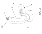
- FIG. 2 is a front view of the same.
- the hearing aid 100 is worn on an ear 1 in a state in which its body case 2 is hooked behind the ear 1.
- the hearing aid 100 comprises a string-shaped sound conductor 3, a coupler 4, an earpiece adapter 5, an earpiece 6, and a ring-shaped engaging component 8.
- the coupler 4 is provided at the top part of the body case 2, and is linked to one end of the string-shaped sound conductor 3.
- the earpiece adapter 5 is attached to the other end of the sound conductor 3, and is linked to the earpiece 6.
- the earpiece 6 in this embodiment is structured such that every part of it is inserted into the external auditory canal 7 of the ear 1, as shown in FIG. 2 .
- the string-shaped sound conductor 3 extends from the end linked to the coupler 4 at the upper part of the body case 2, to the outside of the external auditory canal 7, tracing an approximate arc. From there, as can be seen in FIG. 2 , the sound conductor 3 gently curves toward the external auditory canal 7.
- the ring-shaped engaging component 8 is attached to the earpiece adapter 5. This engaging component 8 comes into contact with the tragus 9, the antitragus 10, and then the antihelix 10a, and as a result the earpiece 6 is stably fixed to the ear 1.
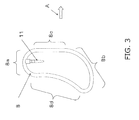
- the engaging component 8 will now be described through reference to FIG. 3 .
- the engaging component 8 is made of a deformable, soft material. Silicone rubber or the like can be used, for example.
- the engaging component 8 has a ring shape and is made up of a convex small arc 8a (an example of a first arc part) disposed on the earpiece 6 side, a convex large arc 8b (an example of a second arc part) that is larger than the convex small arc 8a and is disposed opposite the convex small arc 8a, a front side 8c (an example of a first linking part) that links the front end of the convex small arc 8a and the front end of the convex large arc 8b, and a rear side 8d (an example of a second linking part) that links the rear end of the convex small arc 8a and the rear end of the convex large arc 8b.
- the rear side 8d has a concave shape in which its center part protrudes toward the front side 8c.
- a coupler 11 having a shape that protrudes into the ring shape is molded integrally with the convex small arc 8a of the engaging component 8.
- FIG. 4 is a diagram of the state when the engaging component 8 has been attached to the hearing aid 100.
- the engaging component 8 is coupled to the earpiece adapter 5 by plugging the earpiece adapter 5 into a hole 12 disposed at the entrance to the external auditory canal 7.
- the engaging component 8 is disposed around the entrance to the external auditory canal 7 (see FIG. 2 ).
- the hearing aid 100 When the hearing aid 100 is put on the ear 1, first the body case 2 is disposed behind the ear 1 as shown in FIG. 1 , after which the earpiece 6 is inserted into the external auditory canal 7 as shown in FIG. 2 .
- the engaging component 8 When the engaging component 8 is then put inside the ear 1 as shown in FIG. 2 , first the front side 8c is put on the rear side of the tragus 9.
- the convex large arc 8b is put on the rear side of the antitragus 10. As can be seen from a comparison of FIGS. 4 and 1 , this deforms the convex large arc 8b by pushing it toward the convex small arc 8a side.
- adjustment in the lengthwise direction of the engaging component 8 is performed so as to match the size of the individual's ear.
- the reason the convex large arc 8b of the engaging component 8 is deformed in a state of being pushed to the convex small arc 8a side is that there is a concave shape in which the center part of the rear side 8d protrudes toward the front side 8c.
- the rear side 8d has a shape that allows displacement to the front side 8c, or a configuration that allows deformation by bending, so that the upper end (the convex small arc 8a side) and the lower end (the convex large arc 8b) move closer together.
- the engaging component 8 of the hearing aid 100 has a ring shape constituted by the convex small arc 8a disposed on the earpiece 6 side, the convex large arc 8b that is larger than the convex small arc 8a and is disposed opposite the convex small arc 8a, the front side 8c that links the front end of the convex small arc 8a and the front end of the convex large arc 8b, and the rear side 8d that links the rear end of the convex small arc 8a and the rear end of the convex large arc 8b.
- the rear side 8d has a concave shape in which the center part protrudes toward the front side 8c. With this configuration, there is deformation in the direction in which the rear side 8d of the engaging component 8 is bent, to match the size of the individual wearing the hearing aid 100.
- the size of the engaging component 8 can be adjusted by displacing the rear side 8d of the engaging component 8 in the bending direction, merely by putting the engaging component 8 on the ear. As a result, the fitting of the hearing aid 100 can be simplified.
- the hearing aid pertaining to the above embodiment comprises a body case that is worn behind an ear, a sound conductor 3 that is linked at one end to the body case and is linked at the other end to an earpiece, and an engaging component for holding the earpiece linked to the other end of the sound conductor in the external auditory canal of the ear.
- the engaging component has a ring shape and is made up of a first arc part that is disposed on the earpiece side, a second arc part that is larger than the first arc part and is disposed opposite the first arc part, a first linking part that links one end of the first arc part and one end of the second arc part, and a second linking part that links the other end of the first arc part and the other end of the second arc part.
- the second linking part has a shape such that its center part protrudes toward the first linking part. This constitution allows the hearing aid to be put on more easily.
- the sound conductor 3 is formed by a sound conducting pipe in the above embodiment, but it may instead be formed by a sound signal transmission wire that transmits sound with electrical signals.
- the present invention can be utilized as a hearing aid.
Abstract
Description
- The present invention relates to a behind-the-ear type of hearing aid.
- A conventional hearing aid of this type comprises a body case that is worn behind an ear, and a string-shaped sound conductor that is linked at one end to this body case and at the other end to an earpiece, and there is a known example in which a string-shaped engaging part that engages with the antitragus of the ear is attached to the other end of the sound conductor (see
Patent Literature 1, for example). With this hearing aid, the body case is worn behind an ear, and the earpiece is inserted into the external auditory canal, after which the engaging part is engaged with the antitragus of the ear, which keeps the earpiece from coming out of the external auditory canal. - With the above hearing aid, the string-shaped engaging part is designed to be longer because the size of an ear varies with the individual wearing the hearing aid. Therefore, when a person with small ears wears the hearing aid, the distal end side of the engaging part is cut off with scissors or another such cutting tool to adjust the length. In other words, the engaging part has to be cut with the above-mentioned cutting tool in order to match it to the size of the ear of the individual wearing the hearing aid, and this made the fitting of the hearing aid more difficult.
- In view of this, it has been proposed that a ring-shaped engaging part that engages with the tragus be attached to the other end of the sound conductor of the hearing aid (see
Patent Literature 2, for example). With this hearing aid, one end of a string-shaped engaging part is linked to the other end to form a ring, and the size of this ring can be varied by retracting or extending the other end. This constitution can accommodate differences in the size of the ears of the individuals wearing the hearing aid. - Patent Literature 1:
US Laid-Open Patent Application 2005/0002539
Patent Literature 2:US Laid-Open Patent Application 2006/0215864 - However, as mentioned above, the hearing aid discussed in the above-mentioned
Patent Literature 2 requires the other end of the string-shaped part to be retracted or extended. Thus, in the actual work, after the fitting of the ring-shaped engaging part has been checked in a state in which the hearing aid is worn on one ear, the hearing aid has to be taken off again, and the work of retracting or extending the other end of the string-shaped engaging part must be repeated until the right size is reached, and this complicates the fitting work. - In view of this, it is an object of the present invention to make it easier to fit a hearing aid.
- To solve the stated problem, one aspect of the present invention provides a hearing aid comprising a body case configured to be worn behind an ear, a sound conductor linked at one end to the body case and linked at the other end to an earpiece, and an engaging component configured to hold the earpiece linked to the other end of the sound conductor in the external auditory canal of the ear, wherein the engaging component has a ring shape. The ring shape is constituted by a first arc part disposed on a earpiece side, a second arc part that is larger than the first arc part and is disposed opposite the first arc part, a first linking part that links one end of the first arc part and one end of the second arc part, and a second linking part that links the other end of the first arc part and the other end of the second arc part. The second linking part has a shape such that a center part of the second linking part protrudes toward the first linking part.
- The present invention makes it easier to fit a hearing aid.
-
-
FIG. 1 is a side view of a state in which the hearing aid pertaining to an embodiment of the present invention has been put on an ear; -
FIG. 2 is a front view of a state in which the hearing aid pertaining to the above-mentioned embodiment has been put on an ear; -
FIG. 3 is a side view of the engaging component of the hearing aid; and -
FIG. 4 is a side view of a hearing aid in which the engaging component has been mounted. - An embodiment of the present invention will now be described in detail through reference to the drawings.
-
FIG. 1 is a side view of a state in which thehearing aid 100 pertaining to one embodiment of the present invention has been put on an ear.FIG. 2 is a front view of the same. Thehearing aid 100 is worn on anear 1 in a state in which itsbody case 2 is hooked behind theear 1. - The
hearing aid 100 comprises a string-shaped sound conductor 3, acoupler 4, anearpiece adapter 5, anearpiece 6, and a ring-shapedengaging component 8. - The
coupler 4 is provided at the top part of thebody case 2, and is linked to one end of the string-shaped sound conductor 3. - The
earpiece adapter 5 is attached to the other end of thesound conductor 3, and is linked to theearpiece 6. - The
earpiece 6 in this embodiment is structured such that every part of it is inserted into the external auditory canal 7 of theear 1, as shown inFIG. 2 . - When the
hearing aid 100 is put on theear 1, as can be seen fromFIG. 1 , the string-shaped sound conductor 3 extends from the end linked to thecoupler 4 at the upper part of thebody case 2, to the outside of the external auditory canal 7, tracing an approximate arc. From there, as can be seen inFIG. 2 , thesound conductor 3 gently curves toward the external auditory canal 7. - The ring-shaped
engaging component 8 is attached to theearpiece adapter 5. Thisengaging component 8 comes into contact with thetragus 9, theantitragus 10, and then theantihelix 10a, and as a result theearpiece 6 is stably fixed to theear 1. - The
engaging component 8 will now be described through reference toFIG. 3 . Theengaging component 8 is made of a deformable, soft material. Silicone rubber or the like can be used, for example. - The
engaging component 8 has a ring shape and is made up of a convexsmall arc 8a (an example of a first arc part) disposed on theearpiece 6 side, a convexlarge arc 8b (an example of a second arc part) that is larger than the convexsmall arc 8a and is disposed opposite the convexsmall arc 8a, afront side 8c (an example of a first linking part) that links the front end of the convexsmall arc 8a and the front end of the convexlarge arc 8b, and arear side 8d (an example of a second linking part) that links the rear end of the convexsmall arc 8a and the rear end of the convexlarge arc 8b. Therear side 8d has a concave shape in which its center part protrudes toward thefront side 8c. - A
coupler 11 having a shape that protrudes into the ring shape is molded integrally with the convexsmall arc 8a of theengaging component 8. -
FIG. 4 is a diagram of the state when theengaging component 8 has been attached to thehearing aid 100. - The
engaging component 8 is coupled to theearpiece adapter 5 by plugging theearpiece adapter 5 into ahole 12 disposed at the entrance to the external auditory canal 7. In a state in which theengaging component 8 has been coupled to theearpiece adapter 5, theearpiece 6 is positioned in the deepest part of the external auditory canal 7, and next to theearpiece adapter 5, theengaging component 8 is disposed around the entrance to the external auditory canal 7 (seeFIG. 2 ). - When the
hearing aid 100 is put on theear 1, first thebody case 2 is disposed behind theear 1 as shown inFIG. 1 , after which theearpiece 6 is inserted into the external auditory canal 7 as shown inFIG. 2 . When theengaging component 8 is then put inside theear 1 as shown inFIG. 2 , first thefront side 8c is put on the rear side of thetragus 9. Next, the convexlarge arc 8b is put on the rear side of theantitragus 10. As can be seen from a comparison ofFIGS. 4 and1 , this deforms the convexlarge arc 8b by pushing it toward the convexsmall arc 8a side. At this point, adjustment in the lengthwise direction of theengaging component 8 is performed so as to match the size of the individual's ear. - Thus, the reason the convex
large arc 8b of theengaging component 8 is deformed in a state of being pushed to the convexsmall arc 8a side is that there is a concave shape in which the center part of therear side 8d protrudes toward thefront side 8c. Therear side 8d has a shape that allows displacement to thefront side 8c, or a configuration that allows deformation by bending, so that the upper end (the convexsmall arc 8a side) and the lower end (the convexlarge arc 8b) move closer together. - In this embodiment, the
engaging component 8 of thehearing aid 100 has a ring shape constituted by the convexsmall arc 8a disposed on theearpiece 6 side, the convexlarge arc 8b that is larger than the convexsmall arc 8a and is disposed opposite the convexsmall arc 8a, thefront side 8c that links the front end of the convexsmall arc 8a and the front end of the convexlarge arc 8b, and therear side 8d that links the rear end of the convexsmall arc 8a and the rear end of the convexlarge arc 8b. Therear side 8d has a concave shape in which the center part protrudes toward thefront side 8c. With this configuration, there is deformation in the direction in which therear side 8d of theengaging component 8 is bent, to match the size of the individual wearing thehearing aid 100. - That is, regardless of the size of the ears of the individual wearing the
hearing aid 100, the size of the engagingcomponent 8 can be adjusted by displacing therear side 8d of the engagingcomponent 8 in the bending direction, merely by putting the engagingcomponent 8 on the ear. As a result, the fitting of thehearing aid 100 can be simplified. - Also, in this embodiment, when the
rear side 8d of the engagingcomponent 8 is displaced in the bending direction, momentum comes into play that moves the convexsmall arc 8a and thefront side 8c toward the front of the ear 1 (the direction of the arrow A inFIG. 3 ). As a result, thefront side 8c is pressed against the rear side of thetragus 9 as shown inFIG. 1 . In this state, thefront side 8c is pressed against the rear side of thetragus 9, while the convexlarge arc 8b is pressed against the rear side of theantitragus 10 as shown inFIG. 1 . Consequently, the engagingcomponent 8 is held to theear 1 in a stable state, and theearpiece adapter 5 and theearpiece 6 that are engaged with the engagingcomponent 8 are held in the external auditory canal 7 in an extremely stable state. - As discussed above, the hearing aid pertaining to the above embodiment comprises a body case that is worn behind an ear, a
sound conductor 3 that is linked at one end to the body case and is linked at the other end to an earpiece, and an engaging component for holding the earpiece linked to the other end of the sound conductor in the external auditory canal of the ear. The engaging component has a ring shape and is made up of a first arc part that is disposed on the earpiece side, a second arc part that is larger than the first arc part and is disposed opposite the first arc part, a first linking part that links one end of the first arc part and one end of the second arc part, and a second linking part that links the other end of the first arc part and the other end of the second arc part. The second linking part has a shape such that its center part protrudes toward the first linking part. This constitution allows the hearing aid to be put on more easily. - The present invention is not limited to the above embodiment, of course, and modifications are possible without departing from the gist of the invention.
- For example, the
sound conductor 3 is formed by a sound conducting pipe in the above embodiment, but it may instead be formed by a sound signal transmission wire that transmits sound with electrical signals. - The present invention can be utilized as a hearing aid.
-
- 1
- ear
- 2
- body case
- 3
- sound conductor
- 4
- coupler
- 5
- earpiece adapter
- 6
- earpiece
- 7
- external auditory canal
- 8
- engaging component
- 8a
- convex small arc
- 8b
- convex large arc
- 8c
- front side
- 8d
- rear side
- 9
- tragus
- 10
- antitragus
- 10a
- antihelix
- 11
- coupler
- 12
- hole
- 100
- hearing aid
Claims (7)
- A hearing aid, comprising:a body case configured to be worn behind an ear;a sound conductor linked at one end to the body case and linked at the other end to an earpiece; andan engaging component configured to hold the earpiece linked to the other end of the sound conductor in the external auditory canal of the ear,wherein the engaging component has a ring shape,the ring shape is constituted by a first arc part disposed on a earpiece side, a second arc part that is larger than the first arc part and is disposed opposite the first arc part, a first linking part that links one end of the first arc part and one end of the second arc part, and a second linking part that links the other end of the first arc part and the other end of the second arc part, andthe second linking part has a shape such that a center part of the second linking part protrudes toward the first linking part.
- The hearing aid according to Claim 1,
wherein the first linking part of the engaging component is substantially linear. - The hearing aid according to Claim 1 or 2,
wherein the engaging component includes a coupler configured to hold the other end of the sound conductor. - The hearing aid according to any of Claims 1 to 3,
wherein the sound conductor is formed from a sound conducting pipe. - The hearing aid according to any of Claims 1 to 3,
wherein the sound conductor is formed from a sound signal transmission wire. - The hearing aid according to any of Claims 1 to 5,
wherein the engaging component is made from a deformable material. - The hearing aid according to any of Claims 1 to 6,
wherein the second linking part of the engaging component has such a shape as to displace toward the first linking part when the second arc part has been pushed toward the first arc part.
Applications Claiming Priority (2)
| Application Number | Priority Date | Filing Date | Title |
|---|---|---|---|
| JP2011039795A JP4993023B1 (en) | 2011-02-25 | 2011-02-25 | hearing aid |
| PCT/JP2012/000186 WO2012114644A1 (en) | 2011-02-25 | 2012-01-13 | Hearing aid |
Publications (2)
| Publication Number | Publication Date |
|---|---|
| EP2521379A1 true EP2521379A1 (en) | 2012-11-07 |
| EP2521379A4 EP2521379A4 (en) | 2013-05-22 |
Family
ID=46720442
Family Applications (1)
| Application Number | Title | Priority Date | Filing Date |
|---|---|---|---|
| EP12726568.4A Withdrawn EP2521379A4 (en) | 2011-02-25 | 2012-01-13 | Hearing aid |
Country Status (4)
| Country | Link |
|---|---|
| US (1) | US8538056B2 (en) |
| EP (1) | EP2521379A4 (en) |
| JP (1) | JP4993023B1 (en) |
| WO (1) | WO2012114644A1 (en) |
Cited By (1)
| Publication number | Priority date | Publication date | Assignee | Title |
|---|---|---|---|---|
| US10237641B2 (en) | 2014-10-30 | 2019-03-19 | Sony Corporation | Sound output device and sound guiding device |
Families Citing this family (16)
| Publication number | Priority date | Publication date | Assignee | Title |
|---|---|---|---|---|
| NO328038B1 (en) | 2007-06-01 | 2009-11-16 | Freebit As | Improved uncleanness |
| WO2011068539A2 (en) * | 2009-12-02 | 2011-06-09 | Ernesto Gerardo | Monocular light source positioning device and method for stimulating photoendocrine response |
| ES2650616T3 (en) | 2012-07-27 | 2018-01-19 | Freebit As | Subtragus ear unit |
| KR101535961B1 (en) * | 2014-03-20 | 2015-07-10 | 주식회사 바이오사운드랩 | Auxiliary Device for Wearing Hearing Aid |
| DK3664473T3 (en) * | 2015-12-14 | 2021-08-16 | Gn Hearing As | Hearing aid |
| JP7036002B2 (en) | 2016-03-01 | 2022-03-15 | ソニーグループ株式会社 | Acoustic output device |
| USD847782S1 (en) * | 2017-02-08 | 2019-05-07 | Sennheiser Communications A/S | Snap on-off headset |
| USD847783S1 (en) * | 2017-02-09 | 2019-05-07 | Sennheiser Communications A/S | Headset including an earhook |
| USD847784S1 (en) * | 2017-02-20 | 2019-05-07 | Sennheiser Communications A/S | Headset including a neckband |
| EP3896990A4 (en) * | 2018-12-14 | 2022-01-26 | Sony Group Corporation | Acoustic device and acoustic system |
| US11166093B2 (en) | 2019-03-19 | 2021-11-02 | Logitech Europe S.A. | Earphone device support and case |
| CN112584265B (en) * | 2019-09-27 | 2023-03-17 | 华为技术有限公司 | Earphone set |
| CN111569220B (en) * | 2020-05-26 | 2022-12-16 | 江苏康康同学科技有限公司 | Ear-hanging type flow regulator on medical oxygen hose |
| USD1002583S1 (en) | 2020-12-02 | 2023-10-24 | Logitech Europe S.A. | Combined earphone and earphone case |
| USD974038S1 (en) | 2020-12-02 | 2023-01-03 | Logitech Europe S.A. | Earphone case |
| USD969772S1 (en) | 2020-12-02 | 2022-11-15 | Logitech Europe S.A. | Earphone |
Citations (3)
| Publication number | Priority date | Publication date | Assignee | Title |
|---|---|---|---|---|
| US20060215864A1 (en) * | 2005-03-16 | 2006-09-28 | Widex A/S | Earpiece for a hearing aid and a hearing aid |
| WO2007090407A1 (en) * | 2006-02-10 | 2007-08-16 | 3 Shape A/S | Method and system for creating non-occluding earpieces |
| JP2009089334A (en) * | 2007-10-03 | 2009-04-23 | Harumi Arao | Hearing aid |
Family Cites Families (5)
| Publication number | Priority date | Publication date | Assignee | Title |
|---|---|---|---|---|
| US20020096391A1 (en) * | 2001-01-24 | 2002-07-25 | Smith Richard C. | Flexible ear insert and audio communication link |
| ATE308221T1 (en) | 2003-02-14 | 2005-11-15 | Gn Resound As | HOLDING ELEMENT FOR EARPIECE |
| CA2579358C (en) * | 2004-09-07 | 2011-11-15 | Widex A/S | Earpiece for a hearing aid and a hearing aid |
| JP4482833B2 (en) | 2007-08-23 | 2010-06-16 | ソニー株式会社 | Headphone device |
| US8311253B2 (en) * | 2010-08-16 | 2012-11-13 | Bose Corporation | Earpiece positioning and retaining |
-
2011
- 2011-02-25 JP JP2011039795A patent/JP4993023B1/en active Active
-
2012
- 2012-01-13 US US13/521,140 patent/US8538056B2/en active Active
- 2012-01-13 EP EP12726568.4A patent/EP2521379A4/en not_active Withdrawn
- 2012-01-13 WO PCT/JP2012/000186 patent/WO2012114644A1/en active Application Filing
Patent Citations (3)
| Publication number | Priority date | Publication date | Assignee | Title |
|---|---|---|---|---|
| US20060215864A1 (en) * | 2005-03-16 | 2006-09-28 | Widex A/S | Earpiece for a hearing aid and a hearing aid |
| WO2007090407A1 (en) * | 2006-02-10 | 2007-08-16 | 3 Shape A/S | Method and system for creating non-occluding earpieces |
| JP2009089334A (en) * | 2007-10-03 | 2009-04-23 | Harumi Arao | Hearing aid |
Non-Patent Citations (1)
| Title |
|---|
| See also references of WO2012114644A1 * |
Cited By (2)
| Publication number | Priority date | Publication date | Assignee | Title |
|---|---|---|---|---|
| US10237641B2 (en) | 2014-10-30 | 2019-03-19 | Sony Corporation | Sound output device and sound guiding device |
| US10659863B2 (en) | 2014-10-30 | 2020-05-19 | Sony Corporation | Sound output device and sound guiding device |
Also Published As
| Publication number | Publication date |
|---|---|
| EP2521379A4 (en) | 2013-05-22 |
| JP2012178668A (en) | 2012-09-13 |
| WO2012114644A1 (en) | 2012-08-30 |
| US8538056B2 (en) | 2013-09-17 |
| US20120321114A1 (en) | 2012-12-20 |
| JP4993023B1 (en) | 2012-08-08 |
Similar Documents
| Publication | Publication Date | Title |
|---|---|---|
| US8538056B2 (en) | Hearing aid | |
| CN110177314B (en) | Earphone and support | |
| US8073175B2 (en) | Behind-the-ear type hearing aid | |
| WO2009153221A3 (en) | Hearing system comprising an earpiece | |
| EP3151583A3 (en) | Earbud case with receptacle connector for earbuds | |
| CN110832385A (en) | Eyewear including ear devices | |
| CN110291797B (en) | Sound pickup apparatus and sound pickup method | |
| US9380370B2 (en) | Earphone and adapter for an earphone | |
| EP3490268A1 (en) | Earphone | |
| EP2587838A1 (en) | A hearing aid retainer accessory | |
| US9860651B2 (en) | Behind the ear hearing aid | |
| US8355519B2 (en) | Tool for fitting and removing a receiver of a hearing aid | |
| JP5395300B1 (en) | Hearing aid and lock pin mounting unit | |
| CN111133769B (en) | Ear-worn earphone with removable connection cord | |
| KR101477285B1 (en) | The earphones | |
| KR100850988B1 (en) | Separation prevention unit and ear set having the same | |
| JP5522022B2 (en) | hearing aid | |
| EP2816822B1 (en) | Ear strap for a probe tube | |
| EP3113506A1 (en) | Earphone with channel for cord management | |
| US20090003638A1 (en) | Hearing device with on/off switch and associated method | |
| JP2011193331A (en) | Hearing aid | |
| KR101665684B1 (en) | Earphone | |
| JP2011188229A (en) | Hearing aid | |
| KR20130038094A (en) | Wireless earset that can separate earphone from ear canal |
Legal Events
| Date | Code | Title | Description |
|---|---|---|---|
| PUAI | Public reference made under article 153(3) epc to a published international application that has entered the european phase |
Free format text: ORIGINAL CODE: 0009012 |
|
| 17P | Request for examination filed |
Effective date: 20120621 |
|
| AK | Designated contracting states |
Kind code of ref document: A1 Designated state(s): AL AT BE BG CH CY CZ DE DK EE ES FI FR GB GR HR HU IE IS IT LI LT LU LV MC MK MT NL NO PL PT RO RS SE SI SK SM TR |
|
| A4 | Supplementary search report drawn up and despatched |
Effective date: 20130418 |
|
| RIC1 | Information provided on ipc code assigned before grant |
Ipc: H04R 25/00 20060101AFI20130412BHEP Ipc: H04R 25/02 20060101ALI20130412BHEP |
|
| DAX | Request for extension of the european patent (deleted) | ||
| 17Q | First examination report despatched |
Effective date: 20160412 |
|
| STAA | Information on the status of an ep patent application or granted ep patent |
Free format text: STATUS: THE APPLICATION IS DEEMED TO BE WITHDRAWN |
|
| 18D | Application deemed to be withdrawn |
Effective date: 20160823 |