EP2521378A1 - Behind the ear hearing aid with receiver in the ear - Google Patents
Behind the ear hearing aid with receiver in the ear Download PDFInfo
- Publication number
- EP2521378A1 EP2521378A1 EP11165104A EP11165104A EP2521378A1 EP 2521378 A1 EP2521378 A1 EP 2521378A1 EP 11165104 A EP11165104 A EP 11165104A EP 11165104 A EP11165104 A EP 11165104A EP 2521378 A1 EP2521378 A1 EP 2521378A1
- Authority
- EP
- European Patent Office
- Prior art keywords
- shell
- hearing aid
- ear
- behind
- plug
- Prior art date
- Legal status (The legal status is an assumption and is not a legal conclusion. Google has not performed a legal analysis and makes no representation as to the accuracy of the status listed.)
- Granted
Links
Images





Classifications
-
- H—ELECTRICITY
- H04—ELECTRIC COMMUNICATION TECHNIQUE
- H04R—LOUDSPEAKERS, MICROPHONES, GRAMOPHONE PICK-UPS OR LIKE ACOUSTIC ELECTROMECHANICAL TRANSDUCERS; ELECTRIC HEARING AIDS; PUBLIC ADDRESS SYSTEMS
- H04R25/00—Electric hearing aids
- H04R25/60—Mounting or interconnection of hearing aid parts, e.g. inside tips, housings or to ossicles
-
- H—ELECTRICITY
- H04—ELECTRIC COMMUNICATION TECHNIQUE
- H04R—LOUDSPEAKERS, MICROPHONES, GRAMOPHONE PICK-UPS OR LIKE ACOUSTIC ELECTROMECHANICAL TRANSDUCERS; ELECTRIC HEARING AIDS; PUBLIC ADDRESS SYSTEMS
- H04R25/00—Electric hearing aids
- H04R25/65—Housing parts, e.g. shells, tips or moulds, or their manufacture
-
- H—ELECTRICITY
- H04—ELECTRIC COMMUNICATION TECHNIQUE
- H04R—LOUDSPEAKERS, MICROPHONES, GRAMOPHONE PICK-UPS OR LIKE ACOUSTIC ELECTROMECHANICAL TRANSDUCERS; ELECTRIC HEARING AIDS; PUBLIC ADDRESS SYSTEMS
- H04R2225/00—Details of deaf aids covered by H04R25/00, not provided for in any of its subgroups
- H04R2225/021—Behind the ear [BTE] hearing aids
- H04R2225/0213—Constructional details of earhooks, e.g. shape, material
-
- H—ELECTRICITY
- H04—ELECTRIC COMMUNICATION TECHNIQUE
- H04R—LOUDSPEAKERS, MICROPHONES, GRAMOPHONE PICK-UPS OR LIKE ACOUSTIC ELECTROMECHANICAL TRANSDUCERS; ELECTRIC HEARING AIDS; PUBLIC ADDRESS SYSTEMS
- H04R2225/00—Details of deaf aids covered by H04R25/00, not provided for in any of its subgroups
- H04R2225/021—Behind the ear [BTE] hearing aids
- H04R2225/0216—BTE hearing aids having a receiver in the ear mould
-
- H—ELECTRICITY
- H04—ELECTRIC COMMUNICATION TECHNIQUE
- H04R—LOUDSPEAKERS, MICROPHONES, GRAMOPHONE PICK-UPS OR LIKE ACOUSTIC ELECTROMECHANICAL TRANSDUCERS; ELECTRIC HEARING AIDS; PUBLIC ADDRESS SYSTEMS
- H04R2225/00—Details of deaf aids covered by H04R25/00, not provided for in any of its subgroups
- H04R2225/57—Aspects of electrical interconnection between hearing aid parts
-
- H—ELECTRICITY
- H04—ELECTRIC COMMUNICATION TECHNIQUE
- H04R—LOUDSPEAKERS, MICROPHONES, GRAMOPHONE PICK-UPS OR LIKE ACOUSTIC ELECTROMECHANICAL TRANSDUCERS; ELECTRIC HEARING AIDS; PUBLIC ADDRESS SYSTEMS
- H04R25/00—Electric hearing aids
- H04R25/55—Electric hearing aids using an external connection, either wireless or wired
- H04R25/556—External connectors, e.g. plugs or modules
-
- H—ELECTRICITY
- H04—ELECTRIC COMMUNICATION TECHNIQUE
- H04R—LOUDSPEAKERS, MICROPHONES, GRAMOPHONE PICK-UPS OR LIKE ACOUSTIC ELECTROMECHANICAL TRANSDUCERS; ELECTRIC HEARING AIDS; PUBLIC ADDRESS SYSTEMS
- H04R25/00—Electric hearing aids
- H04R25/60—Mounting or interconnection of hearing aid parts, e.g. inside tips, housings or to ossicles
- H04R25/607—Mounting or interconnection of hearing aid parts, e.g. inside tips, housings or to ossicles of earhooks
Definitions
- This invention relates to a behind the ear hearing aid with a casing part adapted for placing behind the ear of a user and a speaker provided in or near the ear canal and a lead connection between the speaker and the casing part.
- connection or “coupled” as used herein may include wirelessly connected or coupled.
- the term “and/or” includes any and all combinations of one or more of the associated listed items. The steps of any method disclosed herein do not have to be performed in the exact order disclosed, unless expressly stated otherwise.
- a behind the ear hearing aid is provided with a casing part comprising electronics adapted for signal processing where the casing is adapted for placing behind the ear of a user and a speaker is provided in or near the ear canal and leads are arranged between the speaker and the casing part.
- a plug and socket electrical and mechanical interconnection is arranged between the leads and the electronics inside the casing and the mutual motion between the plug and socket parts for establishing connection is in a direction essentially off axis with respect to the axis of the leads at the casing part. In this way pulling at the lead cannot cause disconnection between the plug and socket parts, and a locking mechanism for fastening the plug in the socket is not needed.
- the casing part may comprise two shell elements adapted to be interconnected in order to enclose the electronics.
- the motion between the plug and socket parts in order to un-plug the plug is by this construction enabled only when the two shell elements are disconnected. This further enhances the security of the interconnection between the in the ear and the behind the ear parts of the hearing aid.
- the first shell element is possibly a u-shaped shell adapted to be seated with up-turned legs in the u-shaped intersection between ear and head of the user
- the second shell element is a flat lid element adapted to close off the space between the two legs.
- the lead may pass into the space defined between the first and the second shell element in the parting line between the two shell elements. As the plug in this way is trapped between the two shell elements, it becomes even more difficult to inadvertently pull the plug and lead away from the housing.
- the two shell elements may be coupled to each other at first and second spaced apart connection areas such that the first connection area is provided at the entry point of the lead into the casing.
- To have at least one connection point at the entry point of the lead may aid to ensure, that in- advertent pull on the lead should cause the two shell elements to come apart and release the plug out of the socket.
- the first connection area may comprise releasable interlocking engagement elements between the two shell parts.
- An interlocking engagement between the shell element ensures that they will remain locked together.
- the second connection area may comprise a frictional and/or flexible latch type of connection between the two shell elements. In this way the second connection area may be considerably easier to disconnect, so the lid part will easy come away from the u-shaped shell element in this area.
- the interlocking engagement elements between the two shell parts may comprise an undercut section in one of the two shell parts, and a protrusion in the opposed shell part which fits the undercut section. In this way a sliding or rotational movement between the two shell parts may cause the protrusion to enter into the undercut section.
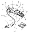
- Fig. 1 shows an exploded view of the hearing aid with the in the ear part 1, the lead 2 and the casing 3 to be seated above and/or behind the users ear (not shown) in the area of intersection between ear and head.
- the casing comprises a u-shaped lower shell part 4, which fits well into this area.
- a further part of the shell is made as a lid 5, which spans the legs of the u-shaped lower shell part.
- a plug 6 and socket 7 is provided at the foremost part of the shell where the plug is attached to the lead 2 and the socket is part of the electronics module 11 inside the shell elements 3.
- the plug is to move downwards (indicated by arrow 10 in fig. 1 ), that is in a direction essentially off axis with respect to the direction indicated by the lead 2 (indicated by dashed line 9 in fig. 1 ) at the connector plug 6.
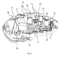
- a sectional view is shown of the foremost part of the hearing aid.
- the plug 6 is shown plugged into the socket 7 of the electronics module 11, and the lead 2 protrudes out between the U-shaped shell part 4 and the lid part 5.
- the lid part 5 of the shell has a protrusion 12, which fits into an undercut 13 of the U-shaped shell 4, whereby a pivotal movement of the lid part 5 with respect to the U-shaped shell part 4 will bring the protrusion 12 into and out of engagement with the undercut 13.
- the lid 5 cannot be moved away from the shell 4 unless the lid is pivoted upwards as indicated by arrow 14.
- the sectional view of figs. 5 and 5a shows the battery 15 and battery drawer 16, and at each their side of the battery 15 downwardly directed latches 17.
- the latches 17 are made to move flexibly towards each other when the lid 5 is pressed down forcing the lathes 17 into the space between the two legs 20 of the U-shaped shell element 4, and at the end of this movement the latches 17 are to form releasable engagement with recesses 21 provided in the sidewalls or legs 20 of u-shaped casing element 4.
- the lid element 5 is best released in this manner when the battery drawer 16 is fully opened. Further such latch/recess pairs may be provided along the length of the hearing aid.
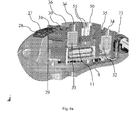
- a number plate 27 is visible in fig. 2 and fig. 6 and 6a .
- the hearing aid is shown in sectional 3D projection but without the lid element and the battery drawer displayed.
- the lid element 5 is taken off, the upper side 28 of the number plate 27 is visible from above, and when the battery door is opened fully up the underside 29 of the number plate 27 is visible from below.
- the electronics module comprises a protruding holder element 31, to which the number plate 27 is attached by through hole 30.
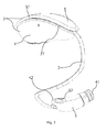
- the receiver element 1 is seen in fig. 3 , and comprises a casing element 40, and shaped slightly curved from the back end to the front end with the sound exit opening 41, such that the receiver element may better be accommodated in the curved part of the ear canal.
- the casing 40 is connected to the lead 2 and also at this part of the casing element 40 a projecting nose 42 is provided next to connection point between lead 2 and casing element 40. The user may exert pressure onto the projecting nose 42 when the receiver element 1 is to be inserted into the ear.
- the projection nose 42 comprises a through hole 43 in which a strip (not shown) of flexible plastics may be mounted. Such a strip may aid in keeping the speaker unit 1 in place in the ear canal. When no such strip is needed, a small plug (not shown) may be inserted into the hole 43, and this plug may preferably comprise a colour marking indicative of the side of the users head to which the hearing aid is suited.
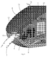
- the electronics module comprises a front microphone 32 and a back-end microphone 33. Both microphones are coupled through sound inlet ducts 34 to an open area 35, 36 below the lid element 5, this open space then being open to the surrounding environment though slits 37 provided between the lid element 5 and the U-shaped casing element 4. Air flows in the open areas 34, 35 will be very limited due to the small size of the slit 36, 37, thus very little wind noise is generated around the sound ducts 32, 33.
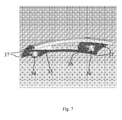
- the inlet structure is shown in a 3D projection in fig. 7 . As seen the slit 37 leads from the exterior and into extended volumes 35, 36 which are shielded from the surroundings, and from these volumes access is granted to the ducts 34 leading into the microphone enclosure. The extended size of the slits 37 will help in ensuring that turbulence noise is kept at a minimum here.
- the electronics module 11 comprises a programming socket 50 with programming pins 51 such that a programming cable 60 may be connected to the hearing aid.
- the programming socket 50 is thus only visible and available for contacting when the lid element 5 is removed. However, the lid element 5 must be in place in order for the proper functioning of the microphones 33,32 such that the inlet structure between the lid 5 and the hearing aid is established. Certain types of measurements are performed using the microphones during programming such as determination of feedback margin which cannot then be performed without the lid 5.
- a special programming adapter 55 is provided as seen in fig. 8 . In fig.
- the adapter 55 is seen in use, and attached to the hearing aid and with the programming plug 61 coupled to the socket 50 in the hearing aid through a central hole 58 in the adapter 55.
- the adapter 55 mimics the shape of the lid element 5, such that the inlet structure shown in fig. 7 is established between the adapter 50 and the hearing aid, and further the outer shape of the hearing aid around the inlet opening to the microphone is also re-established with the adapter 50.
- the microphones will have exactly the same acoustic properties with the programming cable coupled to the hearing aid as without the cable and with the lid element 5 in place. Further this arrangement allows the wired programming to be performed without making a further dedicated lid element to hide and protect the socket as is otherwise the usual practise.
- the adapter comprise a cable holder 57, whereto the programming cable 60 may be coupled such that it is maintained in a position away from the microphone opening slits 37.
- the hearing care professional who is to program the hearing aid will start the procedure by removing the lid 5 and attaching the adapter 55 to the hearing aid in its place.
- the programming plug is inserted into the programming socket 50 and the programming cable is mounted onto the cable holder 57.
- the hearing aid with the programming cable may be seated on the ear with the in the ear part 1 being inserted into the ear of the user.
- Fig. 9 shows a side view of a service tool 70.
- a hook 71 is provided, which may be used to prey open the lid 5 in the direction of the arrow 14.
- the hook 71 is placed under the edge of the lid 5 and using only light force on the tool 70 the lid is moved in the direction of the arrow 14.
- an angled blade part 72 is provided, which fits into a recess 73 provided in the plug 6. With the blade part 72 inserted into the recess 73, the tool is pressed down, in order that the abutment 74 is pressed towards the electronics module 11, and by further pressing down on the opposed end of the service tool a lever lifting force will be transmitted to the plug 6. In this way the plug is lifted out of the apparatus without straining the lead 2 or any other part of the construction.
Landscapes
- Engineering & Computer Science (AREA)
- Health & Medical Sciences (AREA)
- General Health & Medical Sciences (AREA)
- Neurosurgery (AREA)
- Otolaryngology (AREA)
- Physics & Mathematics (AREA)
- Acoustics & Sound (AREA)
- Signal Processing (AREA)
- Manufacturing & Machinery (AREA)
- Headphones And Earphones (AREA)
- Details Of Connecting Devices For Male And Female Coupling (AREA)
Abstract
Description
- This invention relates to a behind the ear hearing aid with a casing part adapted for placing behind the ear of a user and a speaker provided in or near the ear canal and a lead connection between the speaker and the casing part.
- In hearing aids of this kind, there are a number of challenges in making a reliable and easy to operate electro- mechanical construction. The in the ear piece is difficult for the user to place correctly in the ear, and the electric and mechanical connection of the lead with the behind the ear casing part also constitutes a vulnerable element as leads must be exchangeable in order that the user may have a lead with length and shape according to the individual physiognomy and head shape. Further, it may be difficult for some users to determine whether the apparatus in hand is to fit the right side or the left side ear.
- As used herein, the singular forms "a," "an," and "the" are intended to include the plural forms as well (i.e. to have the meaning of "at least one"), unless expressly stated otherwise. It will be further understood that the terms "includes," "comprises," "including," and/or "comprising," when used in this specification, specify the presence of stated features, integers, steps, operations, elements, and/or components, but do not preclude the presence or addition of one or more other features, integers, steps, operations, elements, components, and/or groups thereof. It will be understood that when an element is referred to as being "connected" or "coupled" to another element, it can be directly connected or coupled to the other element or intervening elements maybe present, unless expressly stated otherwise. Furthermore, "connected" or "coupled" as used herein may include wirelessly connected or coupled. As used herein, the term "and/or" includes any and all combinations of one or more of the associated listed items. The steps of any method disclosed herein do not have to be performed in the exact order disclosed, unless expressly stated otherwise.
- In an embodiment of the invention a behind the ear hearing aid is provided with a casing part comprising electronics adapted for signal processing where the casing is adapted for placing behind the ear of a user and a speaker is provided in or near the ear canal and leads are arranged between the speaker and the casing part. A plug and socket electrical and mechanical interconnection is arranged between the leads and the electronics inside the casing and the mutual motion between the plug and socket parts for establishing connection is in a direction essentially off axis with respect to the axis of the leads at the casing part. In this way pulling at the lead cannot cause disconnection between the plug and socket parts, and a locking mechanism for fastening the plug in the socket is not needed.
- The casing part may comprise two shell elements adapted to be interconnected in order to enclose the electronics. The motion between the plug and socket parts in order to un-plug the plug is by this construction enabled only when the two shell elements are disconnected. This further enhances the security of the interconnection between the in the ear and the behind the ear parts of the hearing aid.
- The first shell element is possibly a u-shaped shell adapted to be seated with up-turned legs in the u-shaped intersection between ear and head of the user, and the second shell element is a flat lid element adapted to close off the space between the two legs. The lead may pass into the space defined between the first and the second shell element in the parting line between the two shell elements. As the plug in this way is trapped between the two shell elements, it becomes even more difficult to inadvertently pull the plug and lead away from the housing.
- The two shell elements may be coupled to each other at first and second spaced apart connection areas such that the first connection area is provided at the entry point of the lead into the casing. To have at least one connection point at the entry point of the lead may aid to ensure, that in- advertent pull on the lead should cause the two shell elements to come apart and release the plug out of the socket.
- The first connection area may comprise releasable interlocking engagement elements between the two shell parts. An interlocking engagement between the shell element ensures that they will remain locked together.
- The second connection area may comprise a frictional and/or flexible latch type of connection between the two shell elements. In this way the second connection area may be considerably easier to disconnect, so the lid part will easy come away from the u-shaped shell element in this area.
- The interlocking engagement elements between the two shell parts may comprise an undercut section in one of the two shell parts, and a protrusion in the opposed shell part which fits the undercut section. In this way a sliding or rotational movement between the two shell parts may cause the protrusion to enter into the undercut section.
-
-
Fig. 1 is an exploded view showing a hearing aid in a 3d projection, -
Fig. 2 is an exploded view, but from a different angle, -
Fig. 3 is a projectional view of the hearing aid with the in theear part 1, -
figs. 4 and4a shows a sectional view of the hearing aid, -
Figs. 5 and5a shows a sectional view of the backend of the hearing aid, -
Figs. 6 and6a shows a sectional view of the hearing aid with the upper lid element not displayed, -
Fig. 7 is the inlet air way to from the outside and into the microphone shown in a 3d projection -
Fig. 8 shows an adapter used for programming the hearing aid, -
Fig. 9 shows the hearing aid with the adapter and the hearing aid with programming cable, -
Fig. 10 is a plane view of a service tool. - The figures are schematic and simplified for clarity, and they just show details which are essential to the understanding of the invention, while other details are left out. Throughout, the same reference numerals are used for identical or corresponding parts.
- Further scope of applicability of the present invention will become apparent from the detailed description given hereinafter. However, it should be understood that the detailed description and specific examples, while indicating preferred embodiments of the invention, are given by way of illustration only, since various changes and modifications within the spirit and scope of the invention will become apparent to those skilled in the art from this detailed description.
-
Fig. 1 shows an exploded view of the hearing aid with the in theear part 1, thelead 2 and thecasing 3 to be seated above and/or behind the users ear (not shown) in the area of intersection between ear and head. To this end the casing comprises a u-shapedlower shell part 4, which fits well into this area. A further part of the shell is made as alid 5, which spans the legs of the u-shaped lower shell part. - A
plug 6 andsocket 7 is provided at the foremost part of the shell where the plug is attached to thelead 2 and the socket is part of theelectronics module 11 inside theshell elements 3. In order to plug thelead 2 with theplug 6 into the electronics module inside theshell 3, the plug is to move downwards (indicated byarrow 10 infig. 1 ), that is in a direction essentially off axis with respect to the direction indicated by the lead 2 (indicated by dashed line 9 infig. 1 ) at theconnector plug 6. By this arrangement of the plug and socket connector, it is ensured, that pull at thelead 2 in its length direction cannot pull theplug 6 out of thesocket 7. - As further seen in
fig. 1 , there is an acute angle v between the lead direction 9 and the direction ofinsertion 10, and thereby a pulling force at thelead 2 essentially along the line 9 will translate into a force component directed in the direction of thearrow 10 and no component can exist in the direction opposed to the direction of thearrow 10. Thereby a pulling force at thelead 2 may bring theplug 6 further into thesocket 7 and not out of thesocket 7. - In
figs. 4 and4a a sectional view is shown of the foremost part of the hearing aid. Theplug 6 is shown plugged into thesocket 7 of theelectronics module 11, and thelead 2 protrudes out between the U-shapedshell part 4 and thelid part 5. Thelid part 5 of the shell has aprotrusion 12, which fits into an undercut 13 of theU-shaped shell 4, whereby a pivotal movement of thelid part 5 with respect to theU-shaped shell part 4 will bring theprotrusion 12 into and out of engagement with the undercut 13. Once theprotrusion 12 is seated in theundercut 13, thelid 5 cannot be moved away from theshell 4 unless the lid is pivoted upwards as indicated byarrow 14. This pivotal movement is facilitated by the further connection area between thelid element 5 and theU-shaped shell part 4, which are provided spaced apart from theprotrusion 12 andundercut connection elements 13, and placed at a back end part of the hearing aid. This is shown infig. 5 and5a . Infigs. 5 and5a arrow 14 indicates the direction of movement of thelid element 5 with respect to theU-shaped casing element 4, which should be initiated to remove thelid 5 from theU-shaped element 4. - The sectional view of
figs. 5 and5a shows thebattery 15 andbattery drawer 16, and at each their side of thebattery 15 downwardly directedlatches 17. Thelatches 17 are made to move flexibly towards each other when thelid 5 is pressed down forcing thelathes 17 into the space between the twolegs 20 of theU-shaped shell element 4, and at the end of this movement thelatches 17 are to form releasable engagement withrecesses 21 provided in the sidewalls orlegs 20 of u-shapedcasing element 4. Thelid element 5 is best released in this manner when thebattery drawer 16 is fully opened. Further such latch/recess pairs may be provided along the length of the hearing aid. - Attached to the electronics module 11 a
number plate 27 is visible infig. 2 andfig. 6 and6a . InFig. 6 the hearing aid is shown in sectional 3D projection but without the lid element and the battery drawer displayed. When thelid element 5 is taken off, theupper side 28 of thenumber plate 27 is visible from above, and when the battery door is opened fully up theunderside 29 of thenumber plate 27 is visible from below. Thereby a large display area for information is provided by the number plate arrangement, where the plate is attached to theelectronics module 11 by way of a through-hole 30 provided at an edge part of thenumber plate 27. The electronics module comprises a protrudingholder element 31, to which thenumber plate 27 is attached by throughhole 30. - The
receiver element 1 is seen infig. 3 , and comprises a casing element 40, and shaped slightly curved from the back end to the front end with thesound exit opening 41, such that the receiver element may better be accommodated in the curved part of the ear canal. At the back end, the casing 40 is connected to thelead 2 and also at this part of the casing element 40 a projectingnose 42 is provided next to connection point betweenlead 2 and casing element 40. The user may exert pressure onto the projectingnose 42 when thereceiver element 1 is to be inserted into the ear. - The
projection nose 42 comprises a throughhole 43 in which a strip (not shown) of flexible plastics may be mounted. Such a strip may aid in keeping thespeaker unit 1 in place in the ear canal. When no such strip is needed, a small plug (not shown) may be inserted into thehole 43, and this plug may preferably comprise a colour marking indicative of the side of the users head to which the hearing aid is suited. - The electronics module comprises a
front microphone 32 and a back-end microphone 33. Both microphones are coupled throughsound inlet ducts 34 to anopen area lid element 5, this open space then being open to the surrounding environment thoughslits 37 provided between thelid element 5 and theU-shaped casing element 4. Air flows in theopen areas slit sound ducts fig. 7 . As seen theslit 37 leads from the exterior and into extendedvolumes ducts 34 leading into the microphone enclosure. The extended size of theslits 37 will help in ensuring that turbulence noise is kept at a minimum here. - The
electronics module 11 comprises aprogramming socket 50 withprogramming pins 51 such that aprogramming cable 60 may be connected to the hearing aid. This is seen infig. 6 . Theprogramming socket 50 is thus only visible and available for contacting when thelid element 5 is removed. However, thelid element 5 must be in place in order for the proper functioning of themicrophones lid 5 and the hearing aid is established. Certain types of measurements are performed using the microphones during programming such as determination of feedback margin which cannot then be performed without thelid 5. To this end aspecial programming adapter 55 is provided as seen infig. 8 . Infig. 9 theadapter 55 is seen in use, and attached to the hearing aid and with theprogramming plug 61 coupled to thesocket 50 in the hearing aid through acentral hole 58 in theadapter 55. Theadapter 55 mimics the shape of thelid element 5, such that the inlet structure shown infig. 7 is established between theadapter 50 and the hearing aid, and further the outer shape of the hearing aid around the inlet opening to the microphone is also re-established with theadapter 50. Thereby it is ensured that the microphones will have exactly the same acoustic properties with the programming cable coupled to the hearing aid as without the cable and with thelid element 5 in place. Further this arrangement allows the wired programming to be performed without making a further dedicated lid element to hide and protect the socket as is otherwise the usual practise. - As seen in
fig. 9 the adapter comprise acable holder 57, whereto theprogramming cable 60 may be coupled such that it is maintained in a position away from the microphone opening slits 37. The hearing care professional who is to program the hearing aid will start the procedure by removing thelid 5 and attaching theadapter 55 to the hearing aid in its place. Then the programming plug is inserted into theprogramming socket 50 and the programming cable is mounted onto thecable holder 57. Now the hearing aid with the programming cable may be seated on the ear with the in theear part 1 being inserted into the ear of the user. -
Fig. 9 shows a side view of aservice tool 70. At the one end thereof a hook 71 is provided, which may be used to prey open thelid 5 in the direction of thearrow 14. In use firstly the battery drawer is opened, and then the hook 71 is placed under the edge of thelid 5 and using only light force on thetool 70 the lid is moved in the direction of thearrow 14. In the opposed end anangled blade part 72 is provided, which fits into arecess 73 provided in theplug 6. With theblade part 72 inserted into therecess 73, the tool is pressed down, in order that theabutment 74 is pressed towards theelectronics module 11, and by further pressing down on the opposed end of the service tool a lever lifting force will be transmitted to theplug 6. In this way the plug is lifted out of the apparatus without straining thelead 2 or any other part of the construction.
Claims (7)
- Behind the ear hearing aid with a casing part comprising electronics adapted for signal processing where the casing is adapted for placing behind the ear of a user and a speaker provided in or near the ear canal and leads arranged between the speaker and the casing part whereby a plug and socket electrical and mechanical interconnection is arranged between the leads and the electronics inside the casing and wherein the mutual motion between the plug and socket parts for establishing connection is in a direction essentially off axis to the axis of the leads at the casing part.
- Behind the ear hearing aid as claimed in claim 1, wherein the casing part comprises two shell elements adapted to be interconnected in order to enclose the electronics and wherein the motion between the plug and socket parts in order to un-plug the plug is enabled only when the two shell elements are disconnected.
- Behind the ear hearing aid as claimed in claim 2, wherein the first shell element is a u-shaped shell adapted to be seated with up-turned legs in the u-shaped intersection between ear and head of the user, and the second shell element is a flat lit element adapted to close off the space between the two legs, whereby the lead passes into the space defined between the first and the second shell element in the parting line between the two shell elements.
- Behind the ear hearing aid as claimed in claim 3, wherein the two shell elements are coupled to each other at first and second spaced apart connection areas, wherein the first connection area is provided at the entry point of the lead into the casing.
- Behind the ear hearing aid as claimed in claim 4, wherein the first connection area comprises releasable interlocking engagement elements between the two shell parts.
- Behind the ear hearing aid as claimed in claim 5, wherein the second connection area comprises a frictional and/or flexible latch type of connection between the two shell elements.
- Behind the ear hearing aid as claimed in claim 5, wherein the interlocking engagement elements between the two shell parts comprises an undercut section in one of the two shell parts, and a protrusion in the opposed shell part which fits the undercut section, such that a sliding or rotational movement between the two shell parts may cause the protrusion to enter into the undercut section.
Priority Applications (4)
| Application Number | Priority Date | Filing Date | Title |
|---|---|---|---|
| EP11165104.8A EP2521378B1 (en) | 2011-05-06 | 2011-05-06 | Behind the ear hearing aid with receiver in the ear |
| DK11165104.8T DK2521378T3 (en) | 2011-05-06 | 2011-05-06 | Behind-the-ear hearing aid with receiver in the ear |
| CN201210134111.2A CN102780954B (en) | 2011-05-06 | 2012-05-01 | Behind the ear hearing aid with receiver in the ear |
| US13/464,511 US8953829B2 (en) | 2011-05-06 | 2012-05-04 | Behind the ear hearing aid with receiver in the ear |
Applications Claiming Priority (1)
| Application Number | Priority Date | Filing Date | Title |
|---|---|---|---|
| EP11165104.8A EP2521378B1 (en) | 2011-05-06 | 2011-05-06 | Behind the ear hearing aid with receiver in the ear |
Publications (2)
| Publication Number | Publication Date |
|---|---|
| EP2521378A1 true EP2521378A1 (en) | 2012-11-07 |
| EP2521378B1 EP2521378B1 (en) | 2019-07-10 |
Family
ID=44511690
Family Applications (1)
| Application Number | Title | Priority Date | Filing Date |
|---|---|---|---|
| EP11165104.8A Active EP2521378B1 (en) | 2011-05-06 | 2011-05-06 | Behind the ear hearing aid with receiver in the ear |
Country Status (4)
| Country | Link |
|---|---|
| US (1) | US8953829B2 (en) |
| EP (1) | EP2521378B1 (en) |
| CN (1) | CN102780954B (en) |
| DK (1) | DK2521378T3 (en) |
Cited By (1)
| Publication number | Priority date | Publication date | Assignee | Title |
|---|---|---|---|---|
| US11653161B2 (en) | 2020-08-18 | 2023-05-16 | Gn Hearing A/S | Socket connector for a hearing device |
Families Citing this family (6)
| Publication number | Priority date | Publication date | Assignee | Title |
|---|---|---|---|---|
| USD772417S1 (en) * | 2015-03-25 | 2016-11-22 | IMHear Corporation | Hearing aid |
| DK3139634T3 (en) * | 2015-08-24 | 2019-12-16 | Oticon As | HEARING DEVICE INTERFACE |
| US20170064469A1 (en) * | 2015-08-31 | 2017-03-02 | Oticon A/S | Hearing device |
| EP3169084B1 (en) * | 2015-11-16 | 2022-01-05 | Oticon A/s | Hearing device with a battery drawer |
| EP4258695B1 (en) * | 2018-12-04 | 2025-11-19 | Oticon A/s | Speaker assembly for hearing aid |
| TWI786486B (en) | 2020-12-10 | 2022-12-11 | 仁寶電腦工業股份有限公司 | Hearing aid device |
Citations (5)
| Publication number | Priority date | Publication date | Assignee | Title |
|---|---|---|---|---|
| DE102007009748A1 (en) * | 2007-02-28 | 2008-09-04 | Siemens Audiologische Technik Gmbh | Hearing aid device, has device component worn on or behind ear and earpiece is provided, which is inserted into ear canal of user, and connecting device is provided for removable connection of device component and earpiece |
| EP2160047A2 (en) * | 2008-08-27 | 2010-03-03 | Starkey Laboratories, Inc. | Modular connection assembly for a hearing assistance device |
| US20100067725A1 (en) * | 2008-09-17 | 2010-03-18 | Schumaier Daniel R | Connector for hearing assistance device having reduced mechanical feedback |
| WO2010034353A1 (en) * | 2008-09-26 | 2010-04-01 | Oticon A/S | Hearing aid with exchangeable shell parts and wireless communication |
| WO2011098153A1 (en) * | 2010-02-11 | 2011-08-18 | Siemens Medical Instruments Pte. Ltd. | Behind-the-ear hearing aid having a plug-in connector |
Family Cites Families (13)
| Publication number | Priority date | Publication date | Assignee | Title |
|---|---|---|---|---|
| NL212819A (en) * | 1955-12-13 | 1900-01-01 | Zenith Radio Corp | |
| GB982259A (en) | 1962-04-07 | 1965-02-03 | Hubert Percival Schofield | Improvements in or relating to the sealed connection between elements of a plastic material and pins or studs and the like of rigid or stiff material |
| DE4343702C1 (en) * | 1993-12-21 | 1995-03-09 | Siemens Audiologische Technik | Hearing aid worn on the head |
| JP4294856B2 (en) | 1998-11-24 | 2009-07-15 | フォーナック アーゲー | hearing aid |
| DE59915251D1 (en) * | 1999-06-16 | 2011-04-07 | Phonak Ag | BEHIND EAR HEARING AID |
| DK1915032T3 (en) * | 2006-10-18 | 2012-05-07 | Siemens Audiologische Technik | Hearing aid |
| US7575174B2 (en) | 2006-10-31 | 2009-08-18 | Gordon Michael A | Label and method for attaching a label to an article |
| WO2008095489A1 (en) * | 2007-02-08 | 2008-08-14 | Widex A/S | Receiver in the ear (rite) component for a hearing aid |
| US8385573B2 (en) * | 2007-09-19 | 2013-02-26 | Starkey Laboratories, Inc. | System for hearing assistance device including receiver in the canal |
| CN101953175B (en) * | 2007-12-27 | 2017-04-12 | Gn瑞声达A/S | Modular hearing instrument |
| US8121320B2 (en) * | 2008-01-11 | 2012-02-21 | Songbird Hearing, Inc. | Hearing aid |
| EP2415279B1 (en) | 2009-03-30 | 2014-08-20 | Phonak AG | Method of manufacturing an individually shaped earpiece |
| DE102010040834A1 (en) * | 2010-09-15 | 2012-03-15 | Siemens Medical Instruments Pte. Ltd. | Connector for hearing instrument, hearing instrument and hearing instrument system |
-
2011
- 2011-05-06 DK DK11165104.8T patent/DK2521378T3/en active
- 2011-05-06 EP EP11165104.8A patent/EP2521378B1/en active Active
-
2012
- 2012-05-01 CN CN201210134111.2A patent/CN102780954B/en active Active
- 2012-05-04 US US13/464,511 patent/US8953829B2/en active Active
Patent Citations (5)
| Publication number | Priority date | Publication date | Assignee | Title |
|---|---|---|---|---|
| DE102007009748A1 (en) * | 2007-02-28 | 2008-09-04 | Siemens Audiologische Technik Gmbh | Hearing aid device, has device component worn on or behind ear and earpiece is provided, which is inserted into ear canal of user, and connecting device is provided for removable connection of device component and earpiece |
| EP2160047A2 (en) * | 2008-08-27 | 2010-03-03 | Starkey Laboratories, Inc. | Modular connection assembly for a hearing assistance device |
| US20100067725A1 (en) * | 2008-09-17 | 2010-03-18 | Schumaier Daniel R | Connector for hearing assistance device having reduced mechanical feedback |
| WO2010034353A1 (en) * | 2008-09-26 | 2010-04-01 | Oticon A/S | Hearing aid with exchangeable shell parts and wireless communication |
| WO2011098153A1 (en) * | 2010-02-11 | 2011-08-18 | Siemens Medical Instruments Pte. Ltd. | Behind-the-ear hearing aid having a plug-in connector |
Cited By (3)
| Publication number | Priority date | Publication date | Assignee | Title |
|---|---|---|---|---|
| US11653161B2 (en) | 2020-08-18 | 2023-05-16 | Gn Hearing A/S | Socket connector for a hearing device |
| US11937051B2 (en) | 2020-08-18 | 2024-03-19 | Gn Hearing A/S | Socket connector for a hearing device |
| US12401957B2 (en) | 2020-08-18 | 2025-08-26 | Gn Hearing A/S | Socket connector for a hearing device |
Also Published As
| Publication number | Publication date |
|---|---|
| CN102780954A (en) | 2012-11-14 |
| US20120281864A1 (en) | 2012-11-08 |
| CN102780954B (en) | 2017-04-12 |
| US8953829B2 (en) | 2015-02-10 |
| EP2521378B1 (en) | 2019-07-10 |
| DK2521378T3 (en) | 2019-09-30 |
Similar Documents
| Publication | Publication Date | Title |
|---|---|---|
| US8953829B2 (en) | Behind the ear hearing aid with receiver in the ear | |
| CN102196350B (en) | Electronic assembly and method for operating same | |
| US8139800B2 (en) | Hearing apparatus with a magnetically attached battery holding device | |
| DK2795922T3 (en) | Hearing-aid with jack as ørevoksafskærmning | |
| DK2443842T3 (en) | Hearing aid with a replaceable insert cap | |
| US9980029B2 (en) | Receiver-in-canal assembly comprising a diaphragm and a cable connection | |
| EP2229008A1 (en) | Hearing aid | |
| JP7092654B2 (en) | Receiver / loudspeaker | |
| US11190885B2 (en) | Modular hearing aid | |
| EP1983802A3 (en) | Real ear measurement system using thin tube | |
| EP2091267A1 (en) | Receiver module for a hearing device, hearing device and hearing device earpiece | |
| US9392385B2 (en) | Hearing aid | |
| CN101835356B (en) | Box body for housing an electric apparatus | |
| US9578430B2 (en) | Hearing aid | |
| US20150296314A1 (en) | Receiver/loudspeaker | |
| CN104980873A (en) | Receiver/loudspeaker | |
| EP2930949A1 (en) | A hearing aid | |
| TW201326567A (en) | Fan cage | |
| US9426583B2 (en) | Member with an adhesive surface | |
| EP2930948A1 (en) | Hearing aid | |
| CN213783491U (en) | Building flat board of talkbacking with body temperature monitor function | |
| EP2930946A1 (en) | A hearing aid | |
| CN210574120U (en) | Embedded doorbell casing convenient to change battery | |
| CN104980875A (en) | Hearing aid | |
| US20150296315A1 (en) | Hearing aid receiver and a hearing aid comprising such a receiver |
Legal Events
| Date | Code | Title | Description |
|---|---|---|---|
| PUAI | Public reference made under article 153(3) epc to a published international application that has entered the european phase |
Free format text: ORIGINAL CODE: 0009012 |
|
| AK | Designated contracting states |
Kind code of ref document: A1 Designated state(s): AL AT BE BG CH CY CZ DE DK EE ES FI FR GB GR HR HU IE IS IT LI LT LU LV MC MK MT NL NO PL PT RO RS SE SI SK SM TR |
|
| AX | Request for extension of the european patent |
Extension state: BA ME |
|
| 17P | Request for examination filed |
Effective date: 20130507 |
|
| STAA | Information on the status of an ep patent application or granted ep patent |
Free format text: STATUS: EXAMINATION IS IN PROGRESS |
|
| 17Q | First examination report despatched |
Effective date: 20170316 |
|
| GRAP | Despatch of communication of intention to grant a patent |
Free format text: ORIGINAL CODE: EPIDOSNIGR1 |
|
| STAA | Information on the status of an ep patent application or granted ep patent |
Free format text: STATUS: GRANT OF PATENT IS INTENDED |
|
| INTG | Intention to grant announced |
Effective date: 20180625 |
|
| GRAJ | Information related to disapproval of communication of intention to grant by the applicant or resumption of examination proceedings by the epo deleted |
Free format text: ORIGINAL CODE: EPIDOSDIGR1 |
|
| STAA | Information on the status of an ep patent application or granted ep patent |
Free format text: STATUS: EXAMINATION IS IN PROGRESS |
|
| GRAP | Despatch of communication of intention to grant a patent |
Free format text: ORIGINAL CODE: EPIDOSNIGR1 |
|
| STAA | Information on the status of an ep patent application or granted ep patent |
Free format text: STATUS: GRANT OF PATENT IS INTENDED |
|
| INTC | Intention to grant announced (deleted) | ||
| INTG | Intention to grant announced |
Effective date: 20181119 |
|
| GRAS | Grant fee paid |
Free format text: ORIGINAL CODE: EPIDOSNIGR3 |
|
| GRAA | (expected) grant |
Free format text: ORIGINAL CODE: 0009210 |
|
| STAA | Information on the status of an ep patent application or granted ep patent |
Free format text: STATUS: THE PATENT HAS BEEN GRANTED |
|
| AK | Designated contracting states |
Kind code of ref document: B1 Designated state(s): AL AT BE BG CH CY CZ DE DK EE ES FI FR GB GR HR HU IE IS IT LI LT LU LV MC MK MT NL NO PL PT RO RS SE SI SK SM TR |
|
| REG | Reference to a national code |
Ref country code: GB Ref legal event code: FG4D |
|
| REG | Reference to a national code |
Ref country code: CH Ref legal event code: EP Ref country code: AT Ref legal event code: REF Ref document number: 1154819 Country of ref document: AT Kind code of ref document: T Effective date: 20190715 |
|
| REG | Reference to a national code |
Ref country code: DE Ref legal event code: R096 Ref document number: 602011060305 Country of ref document: DE |
|
| REG | Reference to a national code |
Ref country code: IE Ref legal event code: FG4D |
|
| REG | Reference to a national code |
Ref country code: DK Ref legal event code: T3 Effective date: 20190927 |
|
| REG | Reference to a national code |
Ref country code: NL Ref legal event code: MP Effective date: 20190710 |
|
| REG | Reference to a national code |
Ref country code: LT Ref legal event code: MG4D |
|
| REG | Reference to a national code |
Ref country code: AT Ref legal event code: MK05 Ref document number: 1154819 Country of ref document: AT Kind code of ref document: T Effective date: 20190710 |
|
| PG25 | Lapsed in a contracting state [announced via postgrant information from national office to epo] |
Ref country code: FI Free format text: LAPSE BECAUSE OF FAILURE TO SUBMIT A TRANSLATION OF THE DESCRIPTION OR TO PAY THE FEE WITHIN THE PRESCRIBED TIME-LIMIT Effective date: 20190710 Ref country code: HR Free format text: LAPSE BECAUSE OF FAILURE TO SUBMIT A TRANSLATION OF THE DESCRIPTION OR TO PAY THE FEE WITHIN THE PRESCRIBED TIME-LIMIT Effective date: 20190710 Ref country code: AT Free format text: LAPSE BECAUSE OF FAILURE TO SUBMIT A TRANSLATION OF THE DESCRIPTION OR TO PAY THE FEE WITHIN THE PRESCRIBED TIME-LIMIT Effective date: 20190710 Ref country code: NL Free format text: LAPSE BECAUSE OF FAILURE TO SUBMIT A TRANSLATION OF THE DESCRIPTION OR TO PAY THE FEE WITHIN THE PRESCRIBED TIME-LIMIT Effective date: 20190710 Ref country code: SE Free format text: LAPSE BECAUSE OF FAILURE TO SUBMIT A TRANSLATION OF THE DESCRIPTION OR TO PAY THE FEE WITHIN THE PRESCRIBED TIME-LIMIT Effective date: 20190710 Ref country code: LT Free format text: LAPSE BECAUSE OF FAILURE TO SUBMIT A TRANSLATION OF THE DESCRIPTION OR TO PAY THE FEE WITHIN THE PRESCRIBED TIME-LIMIT Effective date: 20190710 Ref country code: BG Free format text: LAPSE BECAUSE OF FAILURE TO SUBMIT A TRANSLATION OF THE DESCRIPTION OR TO PAY THE FEE WITHIN THE PRESCRIBED TIME-LIMIT Effective date: 20191010 Ref country code: PT Free format text: LAPSE BECAUSE OF FAILURE TO SUBMIT A TRANSLATION OF THE DESCRIPTION OR TO PAY THE FEE WITHIN THE PRESCRIBED TIME-LIMIT Effective date: 20191111 Ref country code: NO Free format text: LAPSE BECAUSE OF FAILURE TO SUBMIT A TRANSLATION OF THE DESCRIPTION OR TO PAY THE FEE WITHIN THE PRESCRIBED TIME-LIMIT Effective date: 20191010 |
|
| PG25 | Lapsed in a contracting state [announced via postgrant information from national office to epo] |
Ref country code: ES Free format text: LAPSE BECAUSE OF FAILURE TO SUBMIT A TRANSLATION OF THE DESCRIPTION OR TO PAY THE FEE WITHIN THE PRESCRIBED TIME-LIMIT Effective date: 20190710 Ref country code: LV Free format text: LAPSE BECAUSE OF FAILURE TO SUBMIT A TRANSLATION OF THE DESCRIPTION OR TO PAY THE FEE WITHIN THE PRESCRIBED TIME-LIMIT Effective date: 20190710 Ref country code: IS Free format text: LAPSE BECAUSE OF FAILURE TO SUBMIT A TRANSLATION OF THE DESCRIPTION OR TO PAY THE FEE WITHIN THE PRESCRIBED TIME-LIMIT Effective date: 20191110 Ref country code: AL Free format text: LAPSE BECAUSE OF FAILURE TO SUBMIT A TRANSLATION OF THE DESCRIPTION OR TO PAY THE FEE WITHIN THE PRESCRIBED TIME-LIMIT Effective date: 20190710 Ref country code: RS Free format text: LAPSE BECAUSE OF FAILURE TO SUBMIT A TRANSLATION OF THE DESCRIPTION OR TO PAY THE FEE WITHIN THE PRESCRIBED TIME-LIMIT Effective date: 20190710 Ref country code: GR Free format text: LAPSE BECAUSE OF FAILURE TO SUBMIT A TRANSLATION OF THE DESCRIPTION OR TO PAY THE FEE WITHIN THE PRESCRIBED TIME-LIMIT Effective date: 20191011 |
|
| PG25 | Lapsed in a contracting state [announced via postgrant information from national office to epo] |
Ref country code: TR Free format text: LAPSE BECAUSE OF FAILURE TO SUBMIT A TRANSLATION OF THE DESCRIPTION OR TO PAY THE FEE WITHIN THE PRESCRIBED TIME-LIMIT Effective date: 20190710 |
|
| PG25 | Lapsed in a contracting state [announced via postgrant information from national office to epo] |
Ref country code: IT Free format text: LAPSE BECAUSE OF FAILURE TO SUBMIT A TRANSLATION OF THE DESCRIPTION OR TO PAY THE FEE WITHIN THE PRESCRIBED TIME-LIMIT Effective date: 20190710 Ref country code: EE Free format text: LAPSE BECAUSE OF FAILURE TO SUBMIT A TRANSLATION OF THE DESCRIPTION OR TO PAY THE FEE WITHIN THE PRESCRIBED TIME-LIMIT Effective date: 20190710 Ref country code: RO Free format text: LAPSE BECAUSE OF FAILURE TO SUBMIT A TRANSLATION OF THE DESCRIPTION OR TO PAY THE FEE WITHIN THE PRESCRIBED TIME-LIMIT Effective date: 20190710 Ref country code: PL Free format text: LAPSE BECAUSE OF FAILURE TO SUBMIT A TRANSLATION OF THE DESCRIPTION OR TO PAY THE FEE WITHIN THE PRESCRIBED TIME-LIMIT Effective date: 20190710 |
|
| PG25 | Lapsed in a contracting state [announced via postgrant information from national office to epo] |
Ref country code: SK Free format text: LAPSE BECAUSE OF FAILURE TO SUBMIT A TRANSLATION OF THE DESCRIPTION OR TO PAY THE FEE WITHIN THE PRESCRIBED TIME-LIMIT Effective date: 20190710 Ref country code: SM Free format text: LAPSE BECAUSE OF FAILURE TO SUBMIT A TRANSLATION OF THE DESCRIPTION OR TO PAY THE FEE WITHIN THE PRESCRIBED TIME-LIMIT Effective date: 20190710 Ref country code: IS Free format text: LAPSE BECAUSE OF FAILURE TO SUBMIT A TRANSLATION OF THE DESCRIPTION OR TO PAY THE FEE WITHIN THE PRESCRIBED TIME-LIMIT Effective date: 20200224 Ref country code: CZ Free format text: LAPSE BECAUSE OF FAILURE TO SUBMIT A TRANSLATION OF THE DESCRIPTION OR TO PAY THE FEE WITHIN THE PRESCRIBED TIME-LIMIT Effective date: 20190710 |
|
| REG | Reference to a national code |
Ref country code: DE Ref legal event code: R097 Ref document number: 602011060305 Country of ref document: DE |
|
| PLBE | No opposition filed within time limit |
Free format text: ORIGINAL CODE: 0009261 |
|
| STAA | Information on the status of an ep patent application or granted ep patent |
Free format text: STATUS: NO OPPOSITION FILED WITHIN TIME LIMIT |
|
| PG2D | Information on lapse in contracting state deleted |
Ref country code: IS |
|
| 26N | No opposition filed |
Effective date: 20200603 |
|
| PG25 | Lapsed in a contracting state [announced via postgrant information from national office to epo] |
Ref country code: SI Free format text: LAPSE BECAUSE OF FAILURE TO SUBMIT A TRANSLATION OF THE DESCRIPTION OR TO PAY THE FEE WITHIN THE PRESCRIBED TIME-LIMIT Effective date: 20190710 |
|
| PG25 | Lapsed in a contracting state [announced via postgrant information from national office to epo] |
Ref country code: MC Free format text: LAPSE BECAUSE OF FAILURE TO SUBMIT A TRANSLATION OF THE DESCRIPTION OR TO PAY THE FEE WITHIN THE PRESCRIBED TIME-LIMIT Effective date: 20190710 |
|
| REG | Reference to a national code |
Ref country code: BE Ref legal event code: MM Effective date: 20200531 |
|
| PG25 | Lapsed in a contracting state [announced via postgrant information from national office to epo] |
Ref country code: LU Free format text: LAPSE BECAUSE OF NON-PAYMENT OF DUE FEES Effective date: 20200506 |
|
| PG25 | Lapsed in a contracting state [announced via postgrant information from national office to epo] |
Ref country code: IE Free format text: LAPSE BECAUSE OF NON-PAYMENT OF DUE FEES Effective date: 20200506 |
|
| PG25 | Lapsed in a contracting state [announced via postgrant information from national office to epo] |
Ref country code: BE Free format text: LAPSE BECAUSE OF NON-PAYMENT OF DUE FEES Effective date: 20200531 |
|
| PG25 | Lapsed in a contracting state [announced via postgrant information from national office to epo] |
Ref country code: MT Free format text: LAPSE BECAUSE OF FAILURE TO SUBMIT A TRANSLATION OF THE DESCRIPTION OR TO PAY THE FEE WITHIN THE PRESCRIBED TIME-LIMIT Effective date: 20190710 Ref country code: CY Free format text: LAPSE BECAUSE OF FAILURE TO SUBMIT A TRANSLATION OF THE DESCRIPTION OR TO PAY THE FEE WITHIN THE PRESCRIBED TIME-LIMIT Effective date: 20190710 |
|
| PG25 | Lapsed in a contracting state [announced via postgrant information from national office to epo] |
Ref country code: MK Free format text: LAPSE BECAUSE OF FAILURE TO SUBMIT A TRANSLATION OF THE DESCRIPTION OR TO PAY THE FEE WITHIN THE PRESCRIBED TIME-LIMIT Effective date: 20190710 |
|
| PGFP | Annual fee paid to national office [announced via postgrant information from national office to epo] |
Ref country code: DE Payment date: 20250429 Year of fee payment: 15 |
|
| PGFP | Annual fee paid to national office [announced via postgrant information from national office to epo] |
Ref country code: GB Payment date: 20250429 Year of fee payment: 15 Ref country code: DK Payment date: 20250429 Year of fee payment: 15 |
|
| PGFP | Annual fee paid to national office [announced via postgrant information from national office to epo] |
Ref country code: FR Payment date: 20250429 Year of fee payment: 15 |
|
| PGFP | Annual fee paid to national office [announced via postgrant information from national office to epo] |
Ref country code: CH Payment date: 20250601 Year of fee payment: 15 |