EP2521193A1 - Electromechanical inverter device - Google Patents
Electromechanical inverter device Download PDFInfo
- Publication number
- EP2521193A1 EP2521193A1 EP11165075A EP11165075A EP2521193A1 EP 2521193 A1 EP2521193 A1 EP 2521193A1 EP 11165075 A EP11165075 A EP 11165075A EP 11165075 A EP11165075 A EP 11165075A EP 2521193 A1 EP2521193 A1 EP 2521193A1
- Authority
- EP
- European Patent Office
- Prior art keywords
- layer
- electromechanical transducer
- transducer device
- electret
- electrode
- Prior art date
- Legal status (The legal status is an assumption and is not a legal conclusion. Google has not performed a legal analysis and makes no representation as to the accuracy of the status listed.)
- Withdrawn
Links
- 239000000463 material Substances 0.000 claims abstract description 73
- 239000002131 composite material Substances 0.000 claims abstract description 49
- 238000000034 method Methods 0.000 claims abstract description 7
- 229920002595 Dielectric elastomer Polymers 0.000 claims description 17
- 238000004519 manufacturing process Methods 0.000 claims description 7
- 229920000642 polymer Polymers 0.000 claims description 7
- -1 polytetrafluoroethylene Polymers 0.000 claims description 7
- 239000000835 fiber Substances 0.000 claims description 5
- 229920000089 Cyclic olefin copolymer Polymers 0.000 claims description 4
- 239000004812 Fluorinated ethylene propylene Substances 0.000 claims description 2
- 239000004697 Polyetherimide Substances 0.000 claims description 2
- 239000004642 Polyimide Substances 0.000 claims description 2
- 239000004721 Polyphenylene oxide Substances 0.000 claims description 2
- 229920001577 copolymer Polymers 0.000 claims description 2
- 150000001925 cycloalkenes Chemical class 0.000 claims description 2
- HQQADJVZYDDRJT-UHFFFAOYSA-N ethene;prop-1-ene Chemical group C=C.CC=C HQQADJVZYDDRJT-UHFFFAOYSA-N 0.000 claims description 2
- 229920002313 fluoropolymer Polymers 0.000 claims description 2
- 229920009441 perflouroethylene propylene Polymers 0.000 claims description 2
- 229920013653 perfluoroalkoxyethylene Polymers 0.000 claims description 2
- 229920003207 poly(ethylene-2,6-naphthalate) Polymers 0.000 claims description 2
- 229920003229 poly(methyl methacrylate) Polymers 0.000 claims description 2
- 229920000515 polycarbonate Polymers 0.000 claims description 2
- 239000004417 polycarbonate Substances 0.000 claims description 2
- 229920000728 polyester Polymers 0.000 claims description 2
- 229920000570 polyether Polymers 0.000 claims description 2
- 229920001601 polyetherimide Polymers 0.000 claims description 2
- 239000011112 polyethylene naphthalate Substances 0.000 claims description 2
- 229920000139 polyethylene terephthalate Polymers 0.000 claims description 2
- 239000005020 polyethylene terephthalate Substances 0.000 claims description 2
- 229920001721 polyimide Polymers 0.000 claims description 2
- 229920000098 polyolefin Polymers 0.000 claims description 2
- 229920001343 polytetrafluoroethylene Polymers 0.000 claims description 2
- 239000004810 polytetrafluoroethylene Substances 0.000 claims description 2
- 229920003225 polyurethane elastomer Polymers 0.000 claims description 2
- 229920002379 silicone rubber Polymers 0.000 claims description 2
- 229920000800 acrylic rubber Polymers 0.000 claims 1
- 229920000058 polyacrylate Polymers 0.000 claims 1
- 230000005684 electric field Effects 0.000 description 15
- 229920001971 elastomer Polymers 0.000 description 7
- 239000000806 elastomer Substances 0.000 description 7
- 230000015556 catabolic process Effects 0.000 description 3
- 239000011231 conductive filler Substances 0.000 description 2
- 230000000694 effects Effects 0.000 description 2
- 239000011263 electroactive material Substances 0.000 description 2
- 239000007788 liquid Substances 0.000 description 2
- 229910052751 metal Inorganic materials 0.000 description 2
- 239000002184 metal Substances 0.000 description 2
- 229910001092 metal group alloy Inorganic materials 0.000 description 2
- 150000002739 metals Chemical class 0.000 description 2
- NIXOWILDQLNWCW-UHFFFAOYSA-M Acrylate Chemical compound [O-]C(=O)C=C NIXOWILDQLNWCW-UHFFFAOYSA-M 0.000 description 1
- 230000001133 acceleration Effects 0.000 description 1
- 230000006978 adaptation Effects 0.000 description 1
- 238000005452 bending Methods 0.000 description 1
- 239000011248 coating agent Substances 0.000 description 1
- 238000000576 coating method Methods 0.000 description 1
- 239000004035 construction material Substances 0.000 description 1
- 230000001419 dependent effect Effects 0.000 description 1
- 238000000151 deposition Methods 0.000 description 1
- 238000009826 distribution Methods 0.000 description 1
- 238000010894 electron beam technology Methods 0.000 description 1
- 239000000945 filler Substances 0.000 description 1
- 239000012774 insulation material Substances 0.000 description 1
- 238000010030 laminating Methods 0.000 description 1
- 239000005022 packaging material Substances 0.000 description 1
- 239000004033 plastic Substances 0.000 description 1
- 229920003023 plastic Polymers 0.000 description 1
- 238000007639 printing Methods 0.000 description 1
- 230000001172 regenerating effect Effects 0.000 description 1
- 230000001953 sensory effect Effects 0.000 description 1
- 238000004154 testing of material Methods 0.000 description 1
Images

Classifications
-
- H—ELECTRICITY
- H10—SEMICONDUCTOR DEVICES; ELECTRIC SOLID-STATE DEVICES NOT OTHERWISE PROVIDED FOR
- H10N—ELECTRIC SOLID-STATE DEVICES NOT OTHERWISE PROVIDED FOR
- H10N30/00—Piezoelectric or electrostrictive devices
- H10N30/80—Constructional details
- H10N30/85—Piezoelectric or electrostrictive active materials
- H10N30/857—Macromolecular compositions
-
- H—ELECTRICITY
- H10—SEMICONDUCTOR DEVICES; ELECTRIC SOLID-STATE DEVICES NOT OTHERWISE PROVIDED FOR
- H10N—ELECTRIC SOLID-STATE DEVICES NOT OTHERWISE PROVIDED FOR
- H10N30/00—Piezoelectric or electrostrictive devices
- H10N30/50—Piezoelectric or electrostrictive devices having a stacked or multilayer structure
-
- H—ELECTRICITY
- H10—SEMICONDUCTOR DEVICES; ELECTRIC SOLID-STATE DEVICES NOT OTHERWISE PROVIDED FOR
- H10N—ELECTRIC SOLID-STATE DEVICES NOT OTHERWISE PROVIDED FOR
- H10N30/00—Piezoelectric or electrostrictive devices
- H10N30/01—Manufacture or treatment
- H10N30/09—Forming piezoelectric or electrostrictive materials
- H10N30/098—Forming organic materials
-
- H—ELECTRICITY
- H10—SEMICONDUCTOR DEVICES; ELECTRIC SOLID-STATE DEVICES NOT OTHERWISE PROVIDED FOR
- H10N—ELECTRIC SOLID-STATE DEVICES NOT OTHERWISE PROVIDED FOR
- H10N30/00—Piezoelectric or electrostrictive devices
- H10N30/20—Piezoelectric or electrostrictive devices with electrical input and mechanical output, e.g. functioning as actuators or vibrators
- H10N30/206—Piezoelectric or electrostrictive devices with electrical input and mechanical output, e.g. functioning as actuators or vibrators using only longitudinal or thickness displacement, e.g. d33 or d31 type devices
-
- H—ELECTRICITY
- H10—SEMICONDUCTOR DEVICES; ELECTRIC SOLID-STATE DEVICES NOT OTHERWISE PROVIDED FOR
- H10N—ELECTRIC SOLID-STATE DEVICES NOT OTHERWISE PROVIDED FOR
- H10N30/00—Piezoelectric or electrostrictive devices
- H10N30/01—Manufacture or treatment
- H10N30/04—Treatments to modify a piezoelectric or electrostrictive property, e.g. polarisation characteristics, vibration characteristics or mode tuning
- H10N30/045—Treatments to modify a piezoelectric or electrostrictive property, e.g. polarisation characteristics, vibration characteristics or mode tuning by polarising
Definitions
- An electret material has the advantage that electrical charges can be stored (permanently) in the electret.
- the predeterminable electrical charge can be generated, for example, by an electrical charge of the electret material.
- An electret material can be positively or negatively charged, ie have positive or negative charges.
- the charge type and / or the charge level can be adapted in particular to an application of the electroactive converter device.
- the electret layer may have a surface charge density that generates a voltage between the electret layer and adjacent electrode of 100 to 2,000V.
- controllable energy sources 42 in particular controllable voltage sources, can be arranged between the respective electrodes 6, 8 and 38.
- controllable energy sources 42 in particular controllable voltage sources, can be arranged between the respective electrodes 6, 8 and 38.
- By changing the voltage can targeted a desired elongation can be achieved.
- a change in voltage of 100 V, in particular of 10 V sufficient changes in strain can be achieved.
- a first electrode 6, for example in the form of an electrically conductive layer 6, can be applied to a first surface of the first electroactive layer 10.
- the electrode 6 can be applied in a planar or structured manner.
- the first electroactive layer 10 can be printed accordingly.
- a electret material 14 having a predeterminable electrical charge can be applied to the second surface of the first electroactive layer 10. It can also be provided that first of all electret material 14 can be applied to an electroactive layer 10, and the electret material is (first) subsequently charged, for example after step 603 or else only after step 604 or 605.
- the electret material 14 may be applied by coating or laminating. In particular, an electret layer 14 can be applied.
- the electret material 14 may be charged by tribocharge, electron beam bombardment, or a corona discharge to create a permanent charge.
- charging can be carried out by a so-called two-electron corona arrangement.
- a needle tension may be at least 20 kV, preferably at least 25 kV and in particular at least 30 kV.
- the charging time can be at least 20 s, preferably at least 25 s and in particular at least 30 s.
Landscapes
- Physics & Mathematics (AREA)
- Spectroscopy & Molecular Physics (AREA)
- Engineering & Computer Science (AREA)
- Manufacturing & Machinery (AREA)
- General Electrical Machinery Utilizing Piezoelectricity, Electrostriction Or Magnetostriction (AREA)
Abstract
Description
Die Erfindung betrifft eine elektromechanische Wandlereinrichtung umfassend einen zwischen einer ersten Elektrode und mindestens einer zweiten Elektrode angeordneten Schichtverbund. Darüber hinaus betrifft die Erfindung ein elektromechanisches Wandlersystem, eine Aktorvorrichtung, eine Generatoreinrichtung und ein Verfahren zum Herstellen einer elektromechanischen Wandlereinrichtung.The invention relates to an electromechanical transducer device comprising a layer composite arranged between a first electrode and at least one second electrode. Moreover, the invention relates to an electromechanical transducer system, an actuator device, a generator device and a method for producing an electromechanical transducer device.
Kunststoffverbundstoffe werden in einer Vielzahl von Anwendungen eingesetzt. Beispielsweise wird ein entsprechender Schichtverbund als Verpackungsmaterial, Isolationsmaterial oder als Konstruktionsmaterial verwendet. Neben diesem herkömmlichen Einsatzzweck, werden Schichtverbunde vermehrt als aktive Komponenten in Generatoranwendungen, Sensoranwendungen oder Aktoranwendungen eingesetzt.Plastic composites are used in a variety of applications. For example, a corresponding layer composite is used as packaging material, insulation material or as construction material. In addition to this conventional application, laminates are increasingly being used as active components in generator applications, sensor applications or actuator applications.
Derartige Schichtverbunde weisen im Allgemeinen mindestens eine elektroaktive Schicht auf, wie eine dielektrische Elastomerschicht. Um eine elektromechanische Wandlereinrichtung zu erhalten, kann eine elektroaktive Schicht beidseitig mit jeweils einer elektrisch leitfähigen Schicht beschichtet sein. Die beiden elektrisch leitfähigen Schichten können als Elektroden dienen. Wird an den Elektroden ein elektrisches Signal, beispielsweise eine Spannung angelegt, dehnt sich die dielektrische Elastomerschicht aus. Insbesondere kann eine Dehnung in Abhängigkeit einer Spannung, welche zwischen 0 V als untere Grenze und einer Durchbruchspannung als obere Grenze liegen kann, erzeugt werden. Umgekehrt kann bei einer mechanischen Einwirkung auf den Schichtverbund ein elektrisches Signal, insbesondere eine Spannung, an den Elektroden abgegriffen werden.Such laminates generally have at least one electroactive layer, such as a dielectric elastomer layer. In order to obtain an electromechanical transducer device, an electroactive layer can be coated on both sides with an electrically conductive layer in each case. The two electrically conductive layers can serve as electrodes. When an electrical signal, for example a voltage, is applied to the electrodes, the dielectric elastomer layer expands. In particular, strain may be generated depending on a voltage which may be between 0 V as a lower limit and a breakdown voltage as an upper limit. Conversely, in the case of a mechanical action on the layer composite, an electrical signal, in particular a voltage, can be picked up at the electrodes.
Nachteilig bei derartigen elektromechanischen Wandlereinrichtungen ist es, dass für eine ausreichende Aktorik, also um eine ausreichend hohe Dehnung der elektroaktiven Schicht zu erzielen, an die Elektroden Spannungen im Bereich von 1000 V angelegt werden müssen. Um bei generatorischen Anwendungen eine hohe Energiemenge zu gewinnen, müssen ähnlich hohe Spannungen angelegt werden. Derart hohe Spannungsänderungen limitieren einen ökonomischen und effizienten Einsatz von elektroaktiven Schichten bzw. von elektromechanischen Wandlereinrichtungen umfassend zumindest einen Schichtverbund mit einer elektroaktiven Schicht jedoch erheblich.A disadvantage of such electromechanical transducer devices is that voltages sufficient in the range of 1000 V must be applied to the electrodes for sufficient actuator functionality, that is, to achieve a sufficiently high elongation of the electroactive layer. In order to obtain a high amount of energy in regenerative applications, similarly high voltages must be applied. However, such high voltage changes considerably limit the economic and efficient use of electroactive layers or of electromechanical converter devices comprising at least one layer composite with an electroactive layer.
Daher liegt der vorliegenden Erfindung die Aufgabe zugrunde, eine elektromechanische Wandlereinrichtung zur Verfügung zu stellen, welche ökonomischer und insbesondere effizienter betrieben werden kann.It is therefore an object of the present invention to provide an electromechanical transducer device which can be operated more economically and in particular more efficiently.
Die zuvor hergeleitete und aufgezeigte Aufgabe wird gemäß einem ersten Aspekt der Erfindung bei einer elektromechanischen Wandlereinrichtung, umfassend mindestens einen zwischen einer ersten Elektrode und mindestens einer zweiten Elektrode angeordneten Schichtverbund, dadurch gelöst, dass der Schichtverbund eine erste elektroaktive Schicht und mindestens eine zweite elektroaktive Schicht aufweist, und dass zwischen der ersten elektroaktiven Schicht und der zweiten elektroaktiven Schicht zumindest abschnittsweise ein Elektretmaterial vorgesehen ist, wobei das Elektretmaterial eine vorgebbare elektrische Ladung aufweist.According to a first aspect of the invention, the previously derived and indicated object is achieved in an electromechanical transducer device comprising at least one layer composite arranged between a first electrode and at least one second electrode in that the layer composite comprises a first electroactive layer and at least one second electroactive layer and that at least in sections an electret material is provided between the first electroactive layer and the second electroactive layer, wherein the electret material has a predeterminable electrical charge.
Im Gegensatz zum Stand der Technik wird gemäß der Lehre der Erfindung eine elektromechanische Wandlereinrichtung zur Verfügung gestellt, welche ökonomischer und insbesondere effizienter betrieben werden kann, indem zwischen zwei elektroaktiven Schichten ein Elektretmaterial mit einer vorgebbaren Ladung angeordnet ist.In contrast to the prior art, according to the teaching of the invention, an electromechanical transducer device is provided, which can be operated more economically and in particular more efficiently by arranging an electret material with a predeterminable charge between two electroactive layers.
Die elektromechanische Wandlereinrichtung umfasst mindestens einen Schichtverbund, dessen äußere Oberflächen mit jeweils einer Elektrode bevorzugt unmittelbar kontaktiert, beispielsweise beschichtet, sind. An der Oberseite des Schichtverbunds kann eine elektrisch leitfähige Schicht angeordnet sein. Ebenso kann an der Unterseite des Schichtverbunds eine elektrisch leitfähige Schicht angeordnet sein. Es versteht sich, dass die Unterseite bzw. die Oberseite nur teilweise bzw. abschnittsweise mit einer elektrisch leitfähigen Schicht beschichtet sein kann. Beispielsweise kann eine strukturierte bzw. segmentierte Schicht gebildet werden. Vorzugsweise kann eine elektrisch leitfähige Schicht aus einem Material gebildet sein, das ausgewählt ist aus der Gruppe umfassend Metalle, Metalllegierungen, leitfähige Oligo- oder Polymere, leitfähige Oxide und/oder mit leitfähigen Füllstoffen gefüllte Polymere.The electromechanical transducer device comprises at least one layer composite, the outer surfaces of which are preferably directly contacted with one electrode, for example coated. An electrically conductive layer can be arranged on the upper side of the layer composite. Likewise, an electrically conductive layer can be arranged on the underside of the layer composite. It is understood that the bottom or the top can be coated only partially or in sections with an electrically conductive layer. For example, a structured or segmented layer can be formed. Preferably, an electrically conductive layer may be formed from a material selected from the group consisting of metals, metal alloys, conductive oligo- or polymers, conductive oxides, and / or polymers filled with conductive fillers.
Der Schichtverbund umfasst mindestens zwei elektroaktive Schichten. Insbesondere können eine obere elektroaktive Schicht und eine untere elektroaktive Schicht vorgesehen sein. Die beiden äußeren Oberflächen der zwei elektroaktiven Schichten können die äußeren Oberflächen des Schichtverbunds bilden, welche mit jeweils einer Elektrode kontaktiert sein können.The layer composite comprises at least two electroactive layers. In particular, an upper electroactive layer and a lower electroactive layer may be provided. The two outer surfaces of the two electroactive layers may form the outer surfaces of the layer composite, which may be contacted with one electrode.
Zwischen der ersten elektroaktiven Schicht und der zweiten elektroaktiven Schicht ist ein Elektretmaterial zumindest abschnittsweise vorgesehen. Bevorzugt kann das Elektretmaterial flächig mit der ersten elektroaktiven Schicht und/oder der zweiten elektroaktiven Schicht verbunden sein. Mit anderen Worten kann das Elektretmaterial die erste elektroaktive Schicht und die zweite elektroaktive Schicht bevorzugt direkt kontaktieren. Es ist insbesondere keine elektrisch leitfähige Schicht zwischen dem Elektretmaterial und einer elektroaktiven Schicht vorgesehen.Between the first electroactive layer and the second electroactive layer, an electret material is provided at least in sections. Preferably, the electret material can be connected in a planar manner to the first electroactive layer and / or the second electroactive layer. In other words, the electret material may be the first electroactive layer and the second Electroactive layer preferably contact directly. In particular, no electrically conductive layer is provided between the electret material and an electroactive layer.
Ein Elektretmaterial weist den Vorteil auf, dass elektrische Ladungen in dem Elektret (permanent) gespeichert werden können. Die vorgebbare elektrische Ladung kann beispielsweise durch eine elektrische Aufladung des Elektretmaterials erzeugt werden. Ein Elektretmaterial kann positiv oder negativ aufgeladen sein, also positive oder negative Ladungen aufweisen. Die Ladungsart und/oder die Ladungshöhe können insbesondere an eine Anwendung der elektroaktiven Wandlereinrichtung angepasst sein. Beispielsweise kann die Elektretschicht eine Oberflächenladungsdichte aufweisen, die eine Spannung zwischen Elektretschicht und benachbarter Elektrode von 100 bis 2000 V erzeugt.An electret material has the advantage that electrical charges can be stored (permanently) in the electret. The predeterminable electrical charge can be generated, for example, by an electrical charge of the electret material. An electret material can be positively or negatively charged, ie have positive or negative charges. The charge type and / or the charge level can be adapted in particular to an application of the electroactive converter device. For example, the electret layer may have a surface charge density that generates a voltage between the electret layer and adjacent electrode of 100 to 2,000V.
Durch die Anordnung von einem Elektretmaterial in dem Schichtverbund, welches eine permanente elektrische Ladung aufweist, wird der Vorteil erzielt, dass die an die Elektrode anzulegende Spannung zur Erzielung einer bestimmten Dehnung im Vergleich zum Stand der Technik deutlich geringer ist. Es ist insbesondere erkannt worden, dass der Effekt, wonach zwischen einem an einer elektroaktiven Schicht angelegten elektrischen Feld und der Dehnung der elektroaktiven Schicht ein näherungsweise quadratischer Zusammenhang besteht, für eine Vielzahl an Anwendungen in vorteilhafter Weise genutzt werden kann. So sind die Dehnungsänderungen bei Spannungsänderungen in einem niedrigen Spannungsbereich gering, während die Dehnungsänderungen bei einer gleichen Spannungsänderung im hohen Spannungsbereich groß sind. Es versteht sich, dass die vorherige Ausführung auch sinngemäß für eine generatorische Anwendung gilt.The arrangement of an electret material in the layer composite, which has a permanent electrical charge, the advantage is achieved that the voltage to be applied to the electrode to achieve a certain elongation compared to the prior art is significantly lower. In particular, it has been recognized that the effect of providing an approximately quadratic relationship between an electric field applied to an electroactive layer and the strain of the electroactive layer can be used to advantage for a variety of applications. Thus, the strain changes are small with voltage changes in a low voltage range, while the strain changes are large with a same voltage change in the high voltage range. It is understood that the previous execution also applies mutatis mutandis to a generator application.
Gemäß einer ersten Ausführungsform der erfindungsgemäßen elektromechanischen Wandlereinrichtung kann in Abhängigkeit der elektrischen Ladung des Elektretmaterials ein Arbeitspunkt der elektromechanischen Wandlereinrichtung einstellbar sein. Wie bereits beschrieben wurde, besteht zwischen der Dehnung einer elektroaktiven Schicht und dem anliegenden elektrischen Feld, bzw. der Spannung ein näherungsweise quadratischer Zusammenhang. Grundsätzlich kann die Dehnung zwischen einem Minimalwert, der sich ergibt, wenn kein elektrisches Feld anliegt, und einem Maximalwert, der durch die Durchbruchsfeldstärke bestimmt wird, eingestellt werden. Durch Einbringen eines eine vorgebbare elektrische Ladung aufweisenden Elektretmaterials kann der Arbeitspunkt von dem Nullpunkt verschoben werden. Der Vorteil einer Verschiebung des Arbeitspunkts liegt darin, dass die für eine bestimmte Dehnungsänderung erforderliche Spannungsänderung deutlich reduziert werden kann. Bevorzugt kann der Arbeitspunkt durch Einbringen einer permanenten Ladung derart geändert werden, dass bereits Spannungsänderungen von 100 V, insbesondere von 10 V, eine ausreichende Dehnungsänderungen bewirken. Eine ausreichende Dehnungsänderung, die von der Anwendung abhängen kann, ist insbesondere eine Dehnung von zumindest 0,1 bis 35 %.According to a first embodiment of the electromechanical transducer device according to the invention, an operating point of the electromechanical transducer device can be adjustable as a function of the electrical charge of the electret material. As already described, there is an approximately quadratic relationship between the elongation of an electroactive layer and the applied electric field or the voltage. Basically, the strain can be set between a minimum value that results when no electric field is applied and a maximum value that is determined by the breakdown field strength. By introducing a electret material having a specifiable electrical charge, the operating point can be shifted from the zero point. The advantage of a shift in the operating point is that the voltage change required for a given strain change can be significantly reduced. Preferably, the operating point can be changed by introducing a permanent charge such that already voltage changes of 100 V, in particular of 10 V, a sufficient strain changes cause. A sufficient change in strain, which may depend on the application, is in particular an elongation of at least 0.1 to 35%.
Grundsätzlich kann das Elektretmaterial in beliebiger Form bereitgestellt werden. Gemäß einer Ausführungsform kann das Elektretmaterial aus Elektretfasern, Elektretkugeln oder einer Elektretschicht gebildet sein. Es kann also eine Zwischenregion aus Elektretfasern oder Elektretkugeln vorgesehen sein. Bevorzugt kann eine Elektretschicht vorgesehen sein, da diese leicht herzustellen ist und eine gleichmäßige Ladungsverteilung über die vorzugsweise gesamte Fläche aufweist.In principle, the electret material can be provided in any form. According to one embodiment, the electret material may be formed of electret fibers, electret spheres or an electret layer. Thus, an intermediate region of electret fibers or electret balls may be provided. Preferably, an electret layer can be provided, since this is easy to manufacture and has a uniform charge distribution over the preferably entire area.
Vorteilhafterweise kann gemäß einer weiteren Ausführungsform der erfindungsgemäßen elektromechanische Wandlereinrichtung das Elektretmaterial ein Material umfassen, das ausgewählt ist aus der Gruppe umfassend Polycarbonat, perfluorierte oder teilfluorierte Polymere und Co-Polymere, Polytetrafluorethylen, Fluorethylenpropylen, Perfluoralkoxyethylen, Polyester, Polyethylenterephthalat, Polyethylennaphthalat, Polyimid, Polyetherimid, Polyether, Polymethyl(meth)acrylat, Cyclo-Olefin-Polymere, Cyclo-Olefin-Copolymere und/oder Polyolefine.Advantageously, according to a further embodiment of the electromechanical transducer device according to the invention, the electret material may comprise a material selected from the group comprising polycarbonate, perfluorinated or partially fluorinated polymers and copolymers, polytetrafluoroethylene, fluorinated ethylene propylene, perfluoroalkoxyethylene, polyester, polyethylene terephthalate, polyethylene naphthalate, polyimide, polyetherimide, Polyether, polymethyl (meth) acrylate, cyclo-olefin polymers, cyclo-olefin copolymers and / or polyolefins.
Als elektroaktive Schichten können verschiedene Materialien bzw. Schichten eingesetzt werden. Insbesondere kann die Wahl des Materials vom späteren Einsatzzweck abhängen. Beispielhafte elektroaktive Schichten sind Piezoschichten, elektrostriktive Polymerschichten, flüssigkristalline Elastomerschichten und dergleichen. Gemäß einer bevorzugten Ausführungsform der elektromechanischen Wandlereinrichtung der vorliegenden Erfindung kann mindestens eine elektroaktive Schicht eine dielektrische Elastomerschicht sein. Insbesondere kann die dielektrische Elastomerschicht eine dielektrische Elastomerfolie sein. Eine dielektrische Elastomerschicht weist vorzugsweise eine relativ hohe Dielektrizitätszahl auf. Darüber hinaus weist eine dielektrische Elastomerschicht vorzugsweise eine niedrige mechanische Steifigkeit auf. Diese Eigenschaften führen zu möglichen Dehnungswerten von bis zu ca. 300 %. Eine dielektrische Elastomerschicht kann insbesondere für eine Aktoranwendung eingesetzt werden. Jedoch eignen sich dielektrische Elastomerschicht ebenso für Sensor- oder Generatoranwendungen. Bevorzugt sind die beiden elektroaktiven Schichten aus dem gleichen Material gebildet.As electroactive layers, various materials or layers can be used. In particular, the choice of material may depend on the later intended use. Exemplary electroactive layers include piezo layers, electrostrictive polymer layers, liquid crystalline elastomer layers, and the like. According to a preferred embodiment of the electromechanical transducer device of the present invention, at least one electroactive layer may be a dielectric elastomer layer. In particular, the dielectric elastomer layer may be a dielectric elastomeric film. A dielectric elastomer layer preferably has a relatively high dielectric constant. In addition, a dielectric elastomer layer preferably has a low mechanical rigidity. These properties lead to possible elongation values of up to approx. 300%. A dielectric elastomer layer can be used in particular for an actuator application. However, dielectric elastomer layers are also suitable for sensor or generator applications. Preferably, the two electroactive layers are formed from the same material.
Ferner kann die dielektrische Elastomerschicht gemäß einer bevorzugten Ausführungsform der Erfindung ein Material umfassen, das beispielsweise ausgewählt ist aus der Gruppe umfassend Polyurethan-Elastomere, Silikon-Elastomere und/oder Acrylat-Elastomere.Further, according to a preferred embodiment of the invention, the dielectric elastomer layer may comprise a material selected, for example, from the group consisting of polyurethane elastomers, silicone elastomers and / or acrylate elastomers.
Die erste elektroaktive Schicht und die zweite elektroaktive Schicht können bevorzugt aus dem gleichen Material gebildet sein. Insbesondere können die sich gegenüberliegenden Schichten auch die gleiche Form, vorzugsweise gleiche Dimensionen, haben. Gemäß einer weiteren Ausführungsform kann die erste elektroaktive Schicht einen ersten Dickenverlauf aufweisen. Die zweite elektroaktive Schicht kann einen zweiten Dickenverlauf aufweisen. Insbesondere kann der erste Dickenverlauf im Wesentlichen gleich dem zweiten Dickenverlauf sein. Durch einen gleichen Dickenverlauf kann jeweils ein gleich starkes elektrisches Feld zwischen der ersten Elektrode und dem Elektretmaterial und der zweiten Elektrode und dem Elektretmaterial erzeugt werden. Grund hierfür ist, dass das elektrische Feld unmittelbar von der Dicke des Zwischenmaterials abhängt.The first electroactive layer and the second electroactive layer may preferably be formed of the same material. In particular, the opposing layers can also have the same shape, preferably equal dimensions. According to a further embodiment, the first electroactive layer may have a first thickness profile. The second electroactive layer may have a second thickness profile. In particular, the first thickness profile can be substantially equal to the second thickness profile. By means of a same thickness curve, an equally strong electric field can be generated in each case between the first electrode and the electret material and the second electrode and the electret material. The reason for this is that the electric field depends directly on the thickness of the intermediate material.
Eine elektroaktive Schicht kann sich zumindest in eine Richtung ausdehnen. Bei einer dielektrischen Elastomerschicht kann das Volumen der Schicht in Folge einer Beaufschlagung mit einem elektrischen Feld im Wesentlichen konstant bleiben. Beispielsweise kann sich bei einem konstanten Volumen die Dicke verringern und gleichzeitig die Fläche vergrößern. Bei einer Ferroelektretfolie kann sich im Wesentlichen (lediglich) die Dicke der Schicht ändern. Die Dehnfähigkeit der elektroaktiven Schichten kann jedoch durch weitere Schichten, die die elektroaktiven Schichten kontaktieren, beschränkt sein. Um beispielsweise bei einer dielektrischen Schicht eine Ausdehnung nicht nur in Dickenrichtung, sondern auch in eine Längsrichtung und/oder in eine Querrichtung zu ermöglichen, kann es erforderlich sein, dass das Elektretmaterial und/oder die Elektroden dehnfähig ausgebildet sind. Beispielsweise können entsprechend nachgiebige Materialien eingesetzt werden, also Materialien, welche eine geringe Steifigkeit aufweisen. Beispielhafte nachgiebige Materialien sind mit elektrisch leitfähigen Füllstoffen gefüllte Elastomere oder Fluorethylenpropylene.An electroactive layer may expand in at least one direction. For a dielectric elastomeric layer, the volume of the layer may remain substantially constant as a result of being subjected to an electric field. For example, at a constant volume, the thickness may decrease while increasing the area. In a ferroelectret film, essentially (only) the thickness of the layer may change. However, the extensibility of the electroactive layers may be limited by other layers contacting the electroactive layers. For example, in order to allow expansion in a dielectric layer not only in the thickness direction but also in a longitudinal direction and / or in a transverse direction, it may be necessary that the electret material and / or the electrodes are designed to be stretchable. For example, according to yielding materials can be used, ie materials which have a low rigidity. Exemplary compliant materials are elastomers filled with electroconductive fillers or fluoroethylenepropylenes.
Um auch steife Materialien einsetzen zu können, kann vorteilhafterweise gemäß einer Ausführungsform der erfindungsgemäßen elektromechanischen Wandlereinrichtung die mindestens eine Elektretschicht ein wellenförmiges Querschnittsprofil aufweisen. Alternativ oder zusätzlich kann mindestens eine Elektrode ein wellenförmiges Querschnittsprofil aufweisen. Eine Schicht kann insbesondere entlang wenigstens einer Richtung ein wellenförmiges Querschnittsprofil aufweisen. Ein wellenförmiges Querschnittsprofil weist Erhebungen und Senkungen auf, welche bevorzugt in einer im Wesentlichen gleichmäßigen Abfolge angeordnet sein können. Es versteht sich, dass auch andere Abfolgen vorgesehen sein können, die sich insbesondere an der späteren Anwendung orientieren können. Bei einer Dehnung wird das wellenförmige Querschnittsprofil gestreckt und so eine Dehnfähigkeit in mindestens eine Richtung erhöht.In order also to be able to use stiff materials, according to an embodiment of the electromechanical transducer device according to the invention, the at least one electret layer can advantageously have a wave-shaped cross-sectional profile. Alternatively or additionally, at least one electrode may have a wave-shaped cross-sectional profile. A layer may in particular have a wave-shaped cross-sectional profile along at least one direction. A wave-shaped cross-sectional profile has elevations and depressions, which can preferably be arranged in a substantially uniform sequence. It is understood that other sequences may be provided, which may be based in particular on the later application. When stretched, the undulating cross-sectional profile is stretched, thus increasing extensibility in at least one direction.
Gemäß einer weiteren Ausführungsform kann eine Energiequelle zwischen der ersten Elektrode und der zweiten Elektrode der elektromechanischen Wandlereinrichtung geschaltet sein. Die Energiequelle kann steuerbar ausgebildet sein. Insbesondere kann die Energiequelle, beispielsweise eine Spannungsquelle, dazu eingerichtet sein, eine Spannungsdifferenz zwischen den beiden angeschlossenen Elektroden zu erzeugen. Durch eine Spannungsdifferenz wird eine der mindestens zwei elektroaktiven Schichten stärker gedehnt, als die andere der mindestens zwei elektroaktiven Schichten. Mit anderen Worten wird eine Biegung der elektromechanischen Wandlereinrichtung erzeugt. Ein Biegewandler kann in einfacher Weise zur Verfügung gestellt werden. Beispielsweise kann durch eine Spannungsdifferenz im Bereich von 100 V und weniger aus einer flächigen Form der Wandlereinrichtung eine Halbkreisform erzeugt werden. Eine asymmetrische elektromechanische Wandlereinrichtung kann bereitgestellt werden. In einer weiteren beispielhaften Ausführung kann die elektromechanische Wandlereinrichtung als Diaphragma ausgebildet sein. Eine taktile Rückmeldung kann beispielsweise erzeugt werden. Vorzugsweise ist in diesem Fall die äußere Elektrode geerdet.According to another embodiment, a power source may be connected between the first electrode and the second electrode of the electromechanical transducer device. The energy source can be designed to be controllable. In particular, the energy source, for example a voltage source, may be configured to provide a voltage difference between the two to produce connected electrodes. Due to a voltage difference, one of the at least two electroactive layers is stretched more strongly than the other of the at least two electroactive layers. In other words, a bend of the electromechanical transducer device is generated. A bending transducer can be provided in a simple manner. For example, a semicircular shape can be generated by a voltage difference in the range of 100 V and less from a flat shape of the transducer device. An asymmetric electromechanical transducer device may be provided. In a further exemplary embodiment, the electromechanical transducer device may be formed as a diaphragm. A tactile feedback can be generated, for example. Preferably, in this case, the outer electrode is grounded.
In einer weiteren Ausführungsform der erfindungsgemäßen Wandlereinrichtung kann die elektromechanische Wandlereinrichtung derart ausgebildet sein, dass ein symmetrischer Betrieb der elektromechanischen Wandlereinrichtung möglich ist. Im Gegensatz zur vorherigen Ausführungsform können die erste und die zweite Elektrode mit dem gleichen Spannungswert beaufschlagt werden. Mit anderen Worten können die beiden Elektroden (jederzeit) auf dem gleichen Potential liegen. Beispielsweise können zwei steuerbare Energiequellen vorgesehen sein. In einfacher Weise kann durch Anlegen einer geringen Spannung im Bereich von 100 V, bevorzugt im Bereich von 10 V, eine ausreichende Aktorik erzielt werden.In a further embodiment of the converter device according to the invention, the electromechanical converter device can be designed such that a symmetrical operation of the electromechanical converter device is possible. In contrast to the previous embodiment, the first and the second electrode can be subjected to the same voltage value. In other words, the two electrodes (at any time) can be at the same potential. For example, two controllable energy sources can be provided. In a simple manner, by applying a low voltage in the range of 100 V, preferably in the range of 10 V, a sufficient actuator can be achieved.
Grundsätzlich können zwei oder mehr zuvor beschriebene Schichtverbunde zu einem Stapel kaskadiert werden. Vorzugsweise kann zwischen jedem Schichtverbund zumindest eine Elektrode vorgesehen sein. Ferner kann zumindest an den äußeren Flächen der kaskadierten Schichtverbunde jeweils eine Elektrode vorgesehen sein.In principle, two or more layer composites described above can be cascaded into a stack. Preferably, at least one electrode can be provided between each layer composite. Furthermore, in each case one electrode can be provided at least on the outer surfaces of the cascaded laminates.
Gemäß einer bevorzugten Ausführungsform kann mindestens ein weiterer mit einer weiteren Elektrode versehener Schichtverbund vorgesehen sein. Der weitere Schichtverbund kann eine erste elektroaktive Schicht und mindestens eine zweite elektroaktive Schicht aufweisen. Beispielsweise können die elektroaktiven Schichten dielektrische Elastomerschichten sein. Zwischen der ersten elektroaktiven Schicht und der zweiten elektroaktiven Schicht kann zumindest abschnittsweise bzw. teilweise ein Elektretmaterial vorgesehen sein. Dieses kann die beiden elektroaktiven Schichten bevorzugt direkt kontaktieren. Beispielsweise kann das Elektretmaterial in Form von Elektretfasern, Elektretkugeln und/oder einer Elektretschicht angeordnet sein. Das Elektretmaterial kann eine vorgebbare elektrische Ladung aufweisen. Insbesondere kann das Elektretmaterial des weiteren Schichtverbunds die gleiche Polarität wie das Elektretmaterial des ersten Schichtverbunds aufweisen. Ferner können auch die Ladungsbeträge von beiden Elektretmaterialien im Wesentlichen gleich sein. Der weitere Schichtverbund kann mit der ersten Elektrode oder der zweiten Elektrode verbunden sein. In einfacher Weise kann eine Stapelung einer Mehrzahl an Schichtverbunden durchgeführt werden. Eine optimale Anpassung der elektromechanischen Wandlereinrichtung an eine spätere Anwendung ist möglich.According to a preferred embodiment, at least one further composite layer provided with a further electrode can be provided. The further layer composite may comprise a first electroactive layer and at least one second electroactive layer. For example, the electroactive layers may be dielectric elastomer layers. Between the first electroactive layer and the second electroactive layer, at least partially or partially an electret material may be provided. This can preferably contact the two electroactive layers directly. For example, the electret material may be arranged in the form of electret fibers, electret spheres and / or an electret layer. The electret material may have a specifiable electrical charge. In particular, the electret material of the further layer composite may have the same polarity as the electret material of the first layer composite. Furthermore, the charge amounts of both electret materials may be substantially the same. The further layer composite may be connected to the first electrode or the second electrode be connected. In a simple manner, a stacking of a plurality of layer composites can be carried out. An optimal adaptation of the electromechanical transducer device to a later application is possible.
Es versteht sich, dass weitere Schichtverbunde und/oder Zwischenschichten zwischen den mindestens zwei Schichtverbunden vorgesehen sein können.It is understood that further layer composites and / or intermediate layers can be provided between the at least two layer composites.
Bevorzugt können sämtliche Schichten einer elektroaktiven Wandlereinrichtung einen parallelen Schichtverlauf aufweisen. Insbesondere kann beispielsweise der Dickenverlauf sämtlicher elektroaktiver Schichten im Wesentlichen gleich sein. Auch kann der Verlauf einer ersten Elektretschicht im Wesentlichen dem Verlauf einer zweiten Elektretschicht entsprechen. In einer weiteren Ausführungsform der erfindungsgemäßen elektromechanischen Wandlereinrichtung kann eine erste Elektretschicht und mindestens eine weitere Elektretschicht bevorzugt entlang derselben Richtung ein wellenförmiges Querschnittsprofil mit Erhebungen und Vertiefungen aufweisen, wobei die Erhebungen und Vertiefungen der ersten Elektretschicht parallel zu den Erhebungen und Vertiefungen der mindestens einen weiteren Elektretschicht verlaufen. Dann kann auch bei einer großen Dehnung die Dicke der Elastomerschicht in der Verlaufsrichtung der Wellen möglichst einheitlich bleiben. Gleiches kann für den Verlauf der mindestens zwei Elektroden gelten.Preferably, all layers of an electroactive converter device may have a parallel layer course. In particular, the thickness profile of all electroactive layers, for example, can be substantially the same. The course of a first electret layer can also essentially correspond to the course of a second electret layer. In a further embodiment of the electromechanical transducer device according to the invention, a first electret layer and at least one further electret layer can preferably have along the same direction a wave-shaped cross-sectional profile with elevations and depressions, wherein the elevations and depressions of the first electret layer extend parallel to the elevations and depressions of the at least one further electret layer , Then, even with a large elongation, the thickness of the elastomer layer in the running direction of the waves remain as uniform as possible. The same can apply to the course of the at least two electrodes.
Ein weiterer Aspekt der vorliegenden Erfindung ist ein elektromechanisches Wandlersystem umfassend eine erste zuvor beschriebene elektromechanische Wandlereinrichtung und mindestens eine mit der ersten elektromechanischen Wandlereinrichtung elektrisch verbindbare zweite zuvor beschriebene elektromechanische Wandlereinrichtung.A further aspect of the present invention is an electromechanical transducer system comprising a first electromechanical transducer device described above and at least one electromechanical transducer device previously described and electrically connectable to the first electromechanical transducer device.
Es versteht sich, dass gemäß weiteren Varianten der Erfindung drei oder mehr elektromechanische Wandlereinrichtungen zusammengeschaltet werden können. Bevorzugt kann das mindestens eine Elektretmaterial der ersten elektromechanischen Wandlereinrichtung eine entgegengesetzte Polarität wie das mindestens eine Elektretmaterial der weiteren elektromechanischen Wandlereinrichtung aufweisen. Beispielsweise kann die erste elektromechanische Wandlereinrichtung mindestens eine Elektretschicht aufweisen, welche positiv geladen ist. Ferner kann die zweite elektromechanische Wandlereinrichtung mindestens eine Elektretschicht aufweisen, welche negativ geladen ist. Bevorzugt kann der Ladungsbetrag der negativen Ladung und der positiven Ladung gleich sein.It is understood that according to further variants of the invention, three or more electromechanical transducer devices can be interconnected. Preferably, the at least one electret material of the first electromechanical transducer device may have an opposite polarity as the at least one electret material of the further electromechanical transducer device. For example, the first electromechanical transducer device may have at least one electret layer which is positively charged. Furthermore, the second electromechanical transducer device may comprise at least one electret layer which is negatively charged. Preferably, the charge amount of the negative charge and the positive charge may be the same.
Gemäß einer ersten Ausführungsform des erfindungsgemäßen elektromechanischen Wandlersystems kann mindestens eine Elektrode der ersten elektromechanischen Wandlereinrichtung mit mindestens einer ersten Elektrode der zweiten elektromechanischen Wandlereinrichtung elektrisch verbindbar oder verbunden sein. Insbesondere können sämtliche Elektroden der ersten elektromechanischen Wandlereinrichtung mit den entsprechenden Elektroden der zweiten elektromechanischen Wandlereinrichtung über separate elektrische Verbindungen miteinander verbunden sein. Vorzugsweise kann das mindestens eine Elektretmaterial der ersten elektromechanischen Wandlereinrichtung eine im Vergleich zum mindestens einen Elektretmaterial der zweiten elektromechanischen Wandlereinrichtung entgegengesetzte Ladung aufweisen. In einfacher Weise kann eine Ausgleichsladung für die erste bzw. zweite elektromechanische Wandlereinrichtung von der zweiten bzw. ersten elektromechanischen Wandlereinrichtung bereitgestellt werden. Grund hierfür ist, dass die jeweils verbundenen Elektroden einen gleichen Spannungsbetrag mit entgegengesetzter Polarität aufweisen.According to a first embodiment of the electromechanical transducer system according to the invention, at least one electrode of the first electromechanical transducer device can be electrically connected or connected to at least one first electrode of the second electromechanical transducer device. In particular, all can Electrodes of the first electromechanical transducer device with the corresponding electrodes of the second electromechanical transducer device via separate electrical connections to be interconnected. Preferably, the at least one electret material of the first electromechanical transducer device may have a charge opposite the at least one electret material of the second electromechanical transducer device. In a simple manner, a compensation charge for the first and second electromechanical converter device can be provided by the second or first electromechanical converter device. The reason for this is that the respectively connected electrodes have the same amount of voltage with opposite polarity.
Beispielsweise kann eine elektromechanische Wandlereinrichtung oder ein elektromechanisches Wandlersystem in strukturierten Drucksensoren für Tastaturen oder Touchpads, Beschleunigungssensoren, Mikrofonen, Lautsprechern, Ultraschallwandlern für Anwendungen in der Medizintechnik, der Meerestechnik oder zur Materialprüfung verwendet werden.For example, an electromechanical transducer device or electromechanical transducer system may be used in structured pressure sensors for keyboards or touchpads, acceleration sensors, microphones, speakers, ultrasonic transducers for medical, marine, or material testing applications.
Ein weiterer Aspekt der vorliegenden Erfindung ist eine Aktorvorrichtung umfassend mindestens eine zuvor beschriebene elektromechanische Wandlereinrichtung. Es versteht sich, dass die Aktorvorrichtung auch zwei oder mehr elektromechanische Wandlereinrichtungen, beispielsweise ein zuvor beschriebenes elektromechanisches System, aufweisen kann. Die Aktorvorrichtung kann darüber hinaus eine Energieversorgung, wie eine Energiequelle, und eine Steuerung zum Steuern der Energiequelle bzw. der elektromechanischen Wandlereinrichtung aufweisen.Another aspect of the present invention is an actuator device comprising at least one previously described electromechanical transducer device. It goes without saying that the actuator device can also have two or more electromechanical converter devices, for example a previously described electromechanical system. The actuator device may further comprise a power supply, such as a power source, and a controller for controlling the power source or the electromechanical transducer device.
Ein weiterer Aspekt der vorliegenden Erfindung ist eine Generatorvorrichtung umfassend mindestens eine zuvor beschriebene elektromechanische Wandlereinrichtung. Es versteht sich, dass die Generatorvorrichtung auch zwei oder mehr elektromechanische Wandlereinrichtungen, beispielsweise ein zuvor beschriebenes elektromechanisches System, aufweisen kann. Die Generatorvorrichtung kann darüber hinaus eine Energieversorgung, wie eine Energiequelle, und eine Steuerung zum Steuern der Energiequelle bzw. der elektromechanischen Wandlereinrichtung aufweisen.Another aspect of the present invention is a generator device comprising at least one electromechanical transducer device as described above. It is understood that the generator device may also comprise two or more electromechanical converter devices, for example a previously described electromechanical system. The generator device may further comprise a power supply, such as a power source, and a controller for controlling the power source or the electromechanical transducer device.
Es versteht sich, dass auch eine Sensorvorrichtung umfassend mindestens eine zuvor beschriebene elektromechanische Wandlereinrichtung vorgesehen sein kann.It goes without saying that a sensor device comprising at least one electromechanical transducer device as described above can also be provided.
Ein noch weiterer Aspekt der vorliegenden Erfindung ist ein Verfahren zum Herstellen einer elektromechanischen Wandlereinrichtung, insbesondere einer zuvor beschriebenen elektromechanischen Wandlereinrichtung. Das Verfahren umfasst die Schritte:
- Bereitstellen einer ersten elektroaktiven Schicht,
- Aufbringen einer ersten Elektrode auf eine erste Oberfläche der ersten elektroaktiven Schicht,
- Aufbringen eines eine vorgebbare elektrische Ladung aufweisenden oder mit einer vorgebbaren elektrischen Ladung aufladbaren Elektretmaterials auf die zweite Oberfläche der ersten elektroaktiven Schicht,
- Aufbringen einer zweiten elektroaktiven Schicht auf das Elektretmaterial, und
- Aufbringen einer zweiten Elektrode auf die zweite elektroaktive Schicht.
- Providing a first electroactive layer,
- Applying a first electrode to a first surface of the first electroactive layer,
- Depositing a electret material having a specifiable electrical charge or with a specifiable electrical charge on the second surface of the first electroactive layer,
- Applying a second electroactive layer to the electret material, and
- Applying a second electrode to the second electroactive layer.
In einfacher Weise kann eine effizient betreibbare elektromechanische Wandlereinrichtung hergestellt werden. Es versteht sich hierbei, dass die Reihenfolge der Schritte beliebig sein kann. Gemäß einer ersten Ausführungsform des erfindungsgemäßen Verfahrens kann mindestens eine elektroaktive Schicht zumindest teilweise mit einer Elektrode bedruckt werden. Beispielsweise kann eine strukturierte Elektrode aufgedruckt werden. Ein Druckverfahren kann in einfacher Weise durchgeführt werden. Insbesondere ist eine Massenproduktion einer elektromechanischen Wandlereinrichtung mit einer erhöhten Produktionsrate möglich.In a simple manner, an efficiently operable electromechanical transducer device can be produced. It is understood that the order of the steps may be arbitrary. According to a first embodiment of the method according to the invention, at least one electroactive layer can be printed at least partially with an electrode. For example, a structured electrode can be printed. A printing method can be easily performed. In particular, mass production of an electromechanical transducer device with an increased production rate is possible.
Es gibt nun eine Vielzahl von Möglichkeiten, die erfindungsgemäße elektromechanische Wandlereinrichtung, das erfindungsgemäße elektromechanische Wandlersystem, die erfindungsgemäße Aktor- und Generatorvorrichtung sowie das erfindungsgemäße Verfahren zum Herstellen einer elektromechanischen Wandlereinrichtung auszugestalten und weiterzuentwickeln. Hierzu sei einerseits verwiesen auf die den unabhängigen Patentansprüchen nachgeordneten Patentansprüche, andererseits auf die Beschreibung von Ausführungsbeispielen in Verbindung mit der Zeichnung. In der Zeichnung zeigt:
- Fig. 1
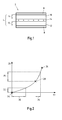
- eine schematische Ansicht eines ersten Ausführungsbeispiels einer elektromechanischen Wandlereinrichtung gemäß der vorliegenden Erfindung;
- Fig. 2
- eine schematische Ansicht eines beispielhaften Verlaufs einer Dehnung einer elektroaktiven Schicht in Abhängigkeit eines angelegten elektrischen Felds;
- Fig. 3
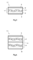
- eine weitere schematische Ansicht eines weiteren Ausführungsbeispiels einer elektromechanischen Wandlereinrichtung gemäß der vorliegenden Erfindung;
- Fig.4
- eine weitere schematische Ansicht eines weiteren Ausführungsbeispiels einer elektromechanischen Wandlereinrichtung gemäß der vorliegenden Erfindung;
- Fig. 5
- eine schematische Ansicht eines Ausführungsbeispiels eines elektromechanischen Wandlersystems gemäß der vorliegenden Erfindung; und
- Fig. 6
- ein Flussdiagramm eines Ausführungsbeispiels eines erfindungsgemäßen Verfahrens zum Herstellen einer elektromechanischen Wandlereinrichtung.
- Fig. 1
- a schematic view of a first embodiment of an electromechanical transducer device according to the present invention;
- Fig. 2
- a schematic view of an exemplary course of an elongation of an electroactive layer in response to an applied electric field;
- Fig. 3
- another schematic view of another embodiment of an electromechanical transducer device according to the present invention;
- Figure 4
- another schematic view of another embodiment of an electromechanical transducer device according to the present invention;
- Fig. 5
- a schematic view of an embodiment of an electromechanical transducer system according to the present invention; and
- Fig. 6
- a flowchart of an embodiment of a method according to the invention for producing an electromechanical transducer device.
Nachfolgend werden gleiche Bezugszeichen für gleiche Elemente verwendet.Hereinafter, like reference numerals are used for like elements.
Die Elektroden 6, 8 können als elektrisch leitfähige Schichten 6, 8 ausgebildet sein. Insbesondere können die Elektroden 6, 8 den Schichtverbund 4 unmittelbar zumindest teilweise kontaktieren. Es versteht sich, dass die Unterseite bzw. die Oberseite des Schichtverbunds 4 nur teilweise mit einer elektrisch leitfähigen Schicht 6, 8 beschichtet sein kann. Beispielsweise kann mindestens eine strukturierte Elektrode 6, 8 aufgedruckt sein.The
Vorzugsweise kann eine elektrisch leitfähige Schicht 6, 8 aus einem Material gebildet sein, das ausgewählt ist aus der Gruppe umfassend Metalle, Metalllegierungen, leitfähige Oligo- oder Polymere, leitfähige Oxide und/oder mit leitfähigen Füllstoffen gefüllte Polymere.Preferably, an electrically
Der Schichtverbund 4 umfasst im vorliegenden Ausführungsbeispiel drei Schichten 10, 12 und 14, wobei die Schicht 14 zwischen den beiden Schichten 10 und 12 angeordnet ist. Insbesondere kontaktiert die Schicht 14 sowohl die obere Schicht 10 als auch die untere Schicht 12 unmittelbar. Insbesondere ist keine weitere Elektrode zwischen der Schicht 14 und der Schicht 10 bzw. 12 angeordnet.In the present exemplary embodiment, the
Dis Schicht 10 ist als eine erste elektroaktive Schicht 10 ausgebildet. Die Schicht 12 ist als eine zweite elektroaktive Schicht 12 ausgebildet. Bevorzugt kann als elektroaktive Schicht 10, 12 eine dielektrische Elastomerschicht 10, 12, wie eine dielektrische Elastomerfolie, eingesetzt werden. Eine dielektrische Elastomerschicht 10, 12 weist vorteilhafterweise eine relativ hohe Dielektrizitätszahl auf. Darüber hinaus weist eine dielektrische Elastomerschicht 10, 12 vorteilhafterweise eine niedrige mechanische Steifigkeit auf. Dies führt zu möglichen Dehnungswerten von bis zu ca. 300 %. Eine dielektrische Elastomerschicht 10, 12 kann insbesondere für eine Aktoranwendung aber auch für generatorische oder sensorische Anwendungen eingesetzt werden.The
Es versteht sich, dass auch andere elektroaktive Schichten verwendet werden können, wie Piezoschichten, elektrostriktive Polymerschichten, flüssigkristalline Elastomerschichten, etc.It is understood that other electroactive layers may be used, such as piezo layers, electrostrictive polymer layers, liquid crystalline elastomer layers, etc.
Die erste dielelektrische Schicht 10 kann eine erste Dicke 16 aufweisen. Die zweite dielelektrische Schicht 12 kann eine zweite Dicke 18 aufweisen. Die erste Dicke 16 kann im Wesentlichen gleich der zweiten Dicke 18 sein. Es versteht sich, dass eine Dicke 16, 18 einer Schicht 10, 12 über die Fläche unterschiedlich ausgebildet sein kann. Bevorzugt können die beiden sich gegenüber liegenden elektroaktiven Schichten 10 und 12 einen im Wesentlichen gleichen Dickenverlauf aufweisen.The
Die Schicht 14 ist im vorliegenden Ausführungsbeispiel eine Elektretschicht 14. Eine Elektretschicht 14 ist zumindest teilweise aus einem Elektretmaterial 14 gebildet. Ein Elektretmaterial 14 weist den Vorteil auf, dass elektrische Ladungen in dem Elektret (permanent) gespeichert werden können. Vor einer Anordnung der Elektretschicht 14 in dem Schichtverbund 4 kann die Elektretschicht 14 beispielsweise elektrisch aufgeladen werden. Es versteht sich, dass die Elektretschicht 14 auch erst nach einer Anordnung der Elektretschicht 14 in dem Schichtverbund 4 aufgeladen werden kann. Zum Beispiel kann das elektrische Aufladen mittels direkter Aufladung oder Coronaentladung durchgeführt werden. Durch die Aufladung weist die Elektretschicht 14 eine vorgebbare dauerhafte Ladung auf. Beispielsweise kann eine positive Ladung mit einem vorgebbaren Wert oder ein negative Ladung mit einem vorgebbaren Wert eingebracht werden. Im vorliegenden Ausführungsbeispiel weist die Elektretschicht 14 positive Ladungen auf.The
Es versteht sich, dass das Elektretmaterial 14 gemäß anderen Varianten der Erfindung auch in geeigneter anderer Form, beispielsweise in Form von Fasern und/oder Kugeln, welche zwischen den beiden elektroaktiven Schichten 10, 12 bevorzugt über die Fläche gleichmäßig verteilt angeordnet werden können, bereitgestellt werden kann.It is understood that the
Wie bereits beschrieben wurde, kann die Elektretschicht 14 die beiden dielektrischen Elastomerschichten 10, 12 direkt kontaktieren. Beispielsweise kann die Elektretschicht 14 beidseitig flächig mit den beiden Elastomerschichten 10, 12 verbunden sein. Es versteht sich, dass die Elektretschicht 14 auch nur teilweise mit den beiden Elastomerschichten 10, 12 verbunden sein kann.As already described, the
Eine Elektretschicht 14, die eine vorgebbare Ladung aufweist, führt dazu, dass sich zwischen der ersten Elektrode 6 und der Elektretschicht 14 ein elektrisches Feld ausbildet. Weiterhin bildet sich aufgrund der Ladung der Elektretschicht 14 ein elektrisches Feld zwischen der zweiten Elektrode 8 und der Elektretschicht 14 aus. Es versteht sich, dass die Elektroden 6, 8 mit einer Ausgleichsspannung verbunden sein können.An
Durch die Anordnung eines Elektretmaterials 14, welche eine vorgebbare Ladung aufweist, zwischen zwei elektroaktiven Schichten 10, 12 kann in einfacher Weise beispielsweise bei einer Aktoranwendung die für eine bestimmte Dehnung anzulegende Spannung signifikant reduziert werden. Dies wird nachfolgend anhand der
Wie in der
Um eine Dehnung des elektroaktiven Materials ausgehend von dem Arbeitspunkt 24 zu bewirken, kann die angelegte Spannung, also das elektrische Feld 22 von 0 V·m-1, um einen Wert 30 erhöht werden. Die führt zu einer Dehnung 20 um den Wert 32. Zu erkennen ist, dass trotz einer relativ deutlichen Erhöhung des elektrischen Feldes 22 um einen Wert 30 die Dehnung 20 lediglich um einen geringen Wert 32 steigt.In order to effect an expansion of the electroactive material starting from the
Erfindungsgemäß ist insbesondere erkannt worden, dass der Arbeitspunkt 24 bei einer elektromechanischen Wandlereinrichtung 2 in einfacher Weise beliebig zwischen dem unteren Grenzwert 24 und dem oberen Grenzwert 26 verschoben werden kann. Der Grund hierfür ist, dass die elektromechanische Wandlereinrichtung 2 bereits mit einer (permanenten) Ladung versehen ist. Mit anderen Worten liegt bereits eine Vorspannung an. Die Vorspannung kann gezielt gewählt werden, indem das Elektretmaterial 14 entsprechend aufgeladen wird. Hierdurch verschiebt sich beispielsweise der Arbeitspunkt 24 zum Arbeitspunkt 28.According to the invention, it has been found, in particular, that the
Wenn ausgehend von dem Arbeitspunkt 28 das elektrische Feld 22 um einen Wert 34, wobei der Wert 34 kleiner als der Wert 30 ist, erhöht wird, ändert sich die Dehnung 20 um einen Wert 36, wobei der Wert 36 größer als der Wert 32 ist. Mit anderen Worten kann bereits durch eine geringe Spannungserhöhung von beispielsweise 10 bis 100 V ausreichend große Dehnungsänderungen erzielt werden.If, starting from the
Im Gegensatz zum Ausführungsbeispiel gemäß
Ein wellenförmiges Querschnittsprofil kann insbesondere immer dann eingesetzt werden, wenn dass Elektretmaterial 14.1 relativ steif, also nur gering dehnfähig, ausgebildet ist. Um die Dehnfähigkeit eines derartigen Elektretmaterials 14.1 zu erhöhen, kann die Elektretschicht 14.1 ein wellenförmiges Querschnittsprofil aufweisen. Bei einer Dehnung wird das wellenförmige Querschnittsprofil gestreckt und so eine Dehnung in mindestens eine Richtung erhöht.A wave-shaped cross-sectional profile can in particular always be used if the electret material 14.1 is relatively stiff, that is, it is only slightly expandable. In order to increase the extensibility of such an electret material 14.1, the electret layer 14.1 may have a wave-shaped cross-sectional profile. When stretched, the wave-shaped cross-sectional profile is stretched to increase elongation in at least one direction.
Ein Beispiel für ein wellenförmiges Profil entlang einer Richtung ist, wenn in einer Elektretschicht 14.1, die eine Dickenrichtung, eine Längsrichtung und eine Querrichtung aufweist, das wellenförmige Profil nur in Längsrichtung gebildet wird. Ein weiteres Beispiel ist der Fall, dass dieses Profil in Längs- und in Querrichtung auftritt. Es versteht sich, dass gemäß anderen Varianten der Erfindung mindestens eine Elektrode 6, 8 ein entsprechendes wellenförmiges Querschnittsprofil aufweisen kann.An example of a wavy profile along one direction is when, in an electret layer 14.1 having a thickness direction, a longitudinal direction and a transverse direction, the undulating profile is formed only in the longitudinal direction. Another example is the case that this profile occurs in the longitudinal and in the transverse direction. It is understood that according to other variants of the invention at least one
Der erste und der zweite Schichtverbund 4.1 entsprechen dem Schichtverbund 4.1 gemäß
Die Elektretschicht 14.1 des ersten Schichtverbunds 4.1 verläuft im Wesentlichen parallel zur Elektretschicht 14.1 des zweiten Schichtverbunds 4.2. Ferner weisen beide Elektretschichten 14.1 vorzugsweise die gleiche Polarität auf, wobei die Elektretschichten 14.1 im vorliegenden Ausführungsbeispiel beide positiv geladen sind. Darüber hinaus können beide Elektretschichten 14.1 mit dem im Wesentlichen gleichen Ladungsbetrag aufgeladen sein.The electret layer 14.1 of the first layer composite 4.1 runs essentially parallel to the electret layer 14.1 of the second layer composite 4.2. Furthermore, both electret layers 14.1 preferably have the same polarity, wherein the electret layers 14.1 are both positively charged in the present exemplary embodiment. In addition, both electret layers 14.1 may be charged with the substantially same charge amount.
Die elektromechanische Wandlereinrichtung 2.3 kann im Wesentlichen der elektromechanischen Wandlereinrichtung 2.2 entsprechen. Auch die elektromechanische Wandlereinrichtung 2.4 kann im Wesentlichen der elektromechanischen Wandlereinrichtung 2.2 entsprechen, wobei im vorliegenden Ausführungsbeispiel die Polarität der Elektretschichten 14 der weiteren elektromechanischen Wandlereinrichtung 2.4 entgegengesetzt zur Polarität der Elektretschichten 14 der ersten elektromechanischen Wandlereinrichtung 2.3 ist. Vorliegend sind die Elektretschichten 14 der ersten elektromechanischen Wandlereinrichtung 2.3 positiv geladen und die Elektretschichten 14 der weiteren elektromechanischen Wandlereinrichtung 2.4 negativ geladen. Bevorzugt können die Ladungsbeträge sämtlicher Elektretschichten 14 des elektromechanischen Wandlersystems 40 im Wesentlichen gleich sein.The electromechanical converter device 2.3 can substantially correspond to the electromechanical converter device 2.2. The electromechanical converter device 2.4 can also essentially correspond to the electromechanical converter device 2.2, wherein in the present exemplary embodiment the polarity of the electret layers 14 of the further electromechanical converter device 2.4 is opposite to the polarity of the electret layers 14 of the first electromechanical converter device 2.3. In the present case, the electret layers 14 of the first electromechanical converter device 2.3 are positively charged and the electret layers 14 of the further electromechanical converter device 2.4 are negatively charged. Preferably, the amounts of charge of all the electret layers 14 of the electro-
Die gleichen Ladungsbeträge mit jedoch unterschiedlicher Polarität führen dazu, dass die jeweiligen Elektroden 6, 8, und 38 eine unterschiedliche Polarität mit einem im Wesentlichen gleichen Ladungsbetrag aufweisen. Vorteilhafterweise können die jeweiligen Elektroden 6, 8, und 38 miteinander elektrisch verbunden sein. In diesem Fall stellt die weitere elektromechanische Wandlereinrichtung 2.4 die Ausgleichsspannung für die erste elektromechanische Wandlereinrichtung 2.3 dar und umgekehrt.However, the same charge amounts with different polarity cause the
Ferner können steuerbare Energiequellen 42, insbesondere steuerbare Spannungsquellen zwischen den jeweiligen Elektroden 6, 8 und 38 angeordnet sein. Durch eine Änderung der Spannung kann gezielt eine gewünschte Dehnung erzielt werden. Vorzugsweise können mit Spannungsänderung von 100 V, insbesondere von 10 V, ausreichende Dehnungsänderungen erreicht werden.Furthermore,
In
In einem ersten Schritt 601 kann eine erste elektroaktive Schicht 10 bereitgestellt werden. Beispielsweise kann eine dielektrische Elastomerfolie bereitgestellt werden.In a
In einem nächsten Schritt 602 kann eine erste Elektrode 6 beispielsweise in Form einer elektrisch leitfähigen Schicht 6 auf eine erste Oberfläche der ersten elektroaktiven Schicht 10 aufgebracht werden. Beispielsweise kann die Elektrode 6 flächig oder strukturiert aufgebracht werden. Insbesondere kann die erste elektroaktive Schicht 10 entsprechend bedruckt werden.In a
Dann kann in einem nächsten Schritt 603 ein eine vorgebbare elektrische Ladung aufweisendes Elektretmaterial 14 auf die zweite Oberfläche der ersten elektroaktiven Schicht 10 aufgebracht werden. Es kann auch vorgesehen sein, dass zunächst Elektretmaterial 14 auf eine elektroaktive Schicht 10 aufgebracht wird kann, und das Elektretmaterial (erst) anschließend, beispielsweise nach Schritt 603 oder auch erst nach Schritt 604 oder 605, aufgeladen wird. Beispielsweise kann das Elektretmaterial 14 durch Beschichten oder Laminieren aufgebracht werden. Insbesondere kann eine Elektretschicht 14 aufgebracht werden.Then, in a
In einem vorherigen Schritt kann das Elektretmaterial 14 beispielsweise durch Triboaufladung, Elektronenstrahlbeschuss, oder eine Coronaentladung aufgeladen werden, um eine permanente Ladung zu erzeugen. Beispielsweise kann ein Aufladen durch eine so genannte Zweielektronen-Corona-Anordnung durchgeführt werden. Eine Nadelspannung kann mindestens 20 kV, vorzugsweise mindestens 25 kV und insbesondere mindestens 30 kV betragen. Die Aufladezeit kann mindestens 20 s, vorzugsweise mindestens 25 s und insbesondere mindestens 30 s betragen.For example, in a previous step, the
Es versteht sich, dass auch zunächst das Elektretmaterial 14 auf eine Oberfläche der ersten elektroaktiven Schicht 10 aufgebracht werden kann und dann erst die erste Elektrode 6. Alternativ können beide Schritte 602 und 603 im Wesentlichen parallel durchgeführt werden.It is understood that initially the
Des Weiteren kann in einem nächsten Schritt 604 eine zweite elektroaktive Schicht 12 auf das Elektretmaterial 14, welches bereits auf der der ersten elektroaktiven Schicht 10 aufgebracht ist, aufgebracht werden. Wenn eine Elektretschicht 14 vorgesehen ist, kann die gegenüber der Oberfläche, welche mit der ersten elektroaktiven Schicht 10 verbunden ist, liegende Oberfläche mit der weiteren elektroaktiven Schicht 12 beschichtet werden. Auch kann gemäß anderen Varianten der Erfindung zunächst eine Elektretschicht 14 bereitgestellt werden und diese beidseitig mit elektroaktiven Schichten 10, 12 beschichtet werden.Furthermore, in a
Schließlich kann auf die die zweite elektroaktive Schicht 12 eine zweite Elektrode 8 aufgebracht werden. Mit anderen Worten wird auf die äußere Oberfläche des Schichtverbunds 4 die zweite Elektrode 8 aufgebracht. Es versteht sich auch hier, dass die Elektrode 8 schon zuvor aufgebracht werden kann und beispielsweise eine zweite mit einer Elektrode 8 versehene elektroaktive Schicht 12 bereitgestellt werden kann.Finally, a
Claims (15)
dadurch gekennzeichnet,
characterized,
und/oder
and or
Priority Applications (6)
| Application Number | Priority Date | Filing Date | Title |
|---|---|---|---|
| EP11165075A EP2521193A1 (en) | 2011-05-06 | 2011-05-06 | Electromechanical inverter device |
| CN201280033393.5A CN103828082A (en) | 2011-05-06 | 2012-05-04 | Electromechanical transducer device |
| PCT/EP2012/058230 WO2012152684A1 (en) | 2011-05-06 | 2012-05-04 | Electromechanical transducer device |
| KR1020137032093A KR20140040142A (en) | 2011-05-06 | 2012-05-04 | Electromechanical transducer device |
| EP12718248.3A EP2705549B1 (en) | 2011-05-06 | 2012-05-04 | Electromechanical transducer device |
| US14/115,150 US20140375170A1 (en) | 2011-05-06 | 2012-05-04 | Electromechanical transducer device |
Applications Claiming Priority (1)
| Application Number | Priority Date | Filing Date | Title |
|---|---|---|---|
| EP11165075A EP2521193A1 (en) | 2011-05-06 | 2011-05-06 | Electromechanical inverter device |
Publications (1)
| Publication Number | Publication Date |
|---|---|
| EP2521193A1 true EP2521193A1 (en) | 2012-11-07 |
Family
ID=44314110
Family Applications (2)
| Application Number | Title | Priority Date | Filing Date |
|---|---|---|---|
| EP11165075A Withdrawn EP2521193A1 (en) | 2011-05-06 | 2011-05-06 | Electromechanical inverter device |
| EP12718248.3A Not-in-force EP2705549B1 (en) | 2011-05-06 | 2012-05-04 | Electromechanical transducer device |
Family Applications After (1)
| Application Number | Title | Priority Date | Filing Date |
|---|---|---|---|
| EP12718248.3A Not-in-force EP2705549B1 (en) | 2011-05-06 | 2012-05-04 | Electromechanical transducer device |
Country Status (5)
| Country | Link |
|---|---|
| US (1) | US20140375170A1 (en) |
| EP (2) | EP2521193A1 (en) |
| KR (1) | KR20140040142A (en) |
| CN (1) | CN103828082A (en) |
| WO (1) | WO2012152684A1 (en) |
Cited By (2)
| Publication number | Priority date | Publication date | Assignee | Title |
|---|---|---|---|---|
| JP2015210244A (en) * | 2014-04-30 | 2015-11-24 | 富士通株式会社 | Pressure-sensitive polymer device |
| CN106884618A (en) * | 2017-03-09 | 2017-06-23 | 西南石油大学 | A kind of rotary propeller type synchronous generator for installing piezoelectric patches and vibration-repressing device and method |
Families Citing this family (13)
| Publication number | Priority date | Publication date | Assignee | Title |
|---|---|---|---|---|
| KR20140050393A (en) * | 2012-10-19 | 2014-04-29 | 삼성전자주식회사 | Textile-based stretchable energy generator |
| DE102013208791B4 (en) * | 2013-05-14 | 2022-02-10 | Robert Bosch Gmbh | Hybrid film for an energy transformer with a method of manufacture |
| JP6743007B2 (en) * | 2014-11-24 | 2020-08-19 | タルケット・ゲーデーエル | Monitoring system with pressure sensor in the floor cover |
| KR101714122B1 (en) * | 2014-11-24 | 2017-03-10 | 서울과학기술대학교 산학협력단 | Complex for triboelectric generator, preparation method thereof and triboelectric generator comprising the complex |
| JP2018059042A (en) | 2016-09-28 | 2018-04-12 | 住友理工株式会社 | Dielectric elastomer material and transducer using the same |
| CN108347192B (en) * | 2017-01-23 | 2019-09-27 | 北京纳米能源与系统研究所 | Electret self power generation wearable device |
| CN106771676A (en) * | 2017-01-27 | 2017-05-31 | 中国计量大学 | Based on the electric-field sensor probe that electrostriction material and electret are constructed |
| JP6831106B2 (en) * | 2017-05-09 | 2021-02-17 | 学校法人 関西大学 | Generator, generator and pressure sensor |
| DE102018221053A1 (en) | 2018-04-05 | 2019-10-10 | Continental Reifen Deutschland Gmbh | Apparatus for measuring a mechanical force comprising first, second, third, fourth and fifth layers and the uses of the apparatus and tires or engineering rubber articles comprising the apparatus |
| US20210273583A1 (en) * | 2018-06-28 | 2021-09-02 | 3M Innovative Properties Company | Low Voltage Electrostatic Jamming Device |
| CN109687758B (en) * | 2019-02-27 | 2020-08-18 | 同济大学 | Flexible ultrasonic suspension device |
| CN110572072B (en) * | 2019-09-06 | 2020-12-22 | 北京纳米能源与系统研究所 | Hybrid nano power generation structure, manufacturing method thereof, energy supply device and sensor |
| JP7505741B2 (en) | 2020-05-20 | 2024-06-25 | 国立大学法人東京工業大学 | Thin-film artificial skin |
Citations (1)
| Publication number | Priority date | Publication date | Assignee | Title |
|---|---|---|---|---|
| WO2007029275A1 (en) * | 2005-09-05 | 2007-03-15 | Federico Carpi | Electroactive polymer based actuator, sensor and generator with folded configuration |
Family Cites Families (3)
| Publication number | Priority date | Publication date | Assignee | Title |
|---|---|---|---|---|
| US5202600A (en) * | 1988-08-31 | 1993-04-13 | Seikosha Co., Ltd. | Piezoelectric device and related converting devices |
| KR100512960B1 (en) * | 2002-09-26 | 2005-09-07 | 삼성전자주식회사 | Flexible MEMS transducer and its manufacturing method, and flexible MEMS wireless microphone |
| CN100435371C (en) * | 2006-03-23 | 2008-11-19 | 同济大学 | Method for preparing porous polymer piezo-electric electret thin film |
-
2011
- 2011-05-06 EP EP11165075A patent/EP2521193A1/en not_active Withdrawn
-
2012
- 2012-05-04 KR KR1020137032093A patent/KR20140040142A/en not_active Application Discontinuation
- 2012-05-04 EP EP12718248.3A patent/EP2705549B1/en not_active Not-in-force
- 2012-05-04 WO PCT/EP2012/058230 patent/WO2012152684A1/en active Application Filing
- 2012-05-04 US US14/115,150 patent/US20140375170A1/en not_active Abandoned
- 2012-05-04 CN CN201280033393.5A patent/CN103828082A/en active Pending
Patent Citations (1)
| Publication number | Priority date | Publication date | Assignee | Title |
|---|---|---|---|---|
| WO2007029275A1 (en) * | 2005-09-05 | 2007-03-15 | Federico Carpi | Electroactive polymer based actuator, sensor and generator with folded configuration |
Non-Patent Citations (2)
| Title |
|---|
| GERHARD-MULTHAUPT R ET AL: "Preliminary study of multi-layer space-charge electrets with piezoelectric properties from porous and non-porous Teflon films", ELECTRETS, 1999. ISE 10. PROCEEDINGS. 10TH INTERNATIONAL SYMPOSIUM ON ATHENS, GREECE 22-24 SEPT. 1999, PISCATAWAY, NJ, USA,IEEE, US, 22 September 1999 (1999-09-22), pages 273 - 276, XP010376541, ISBN: 978-0-7803-5025-0, DOI: 10.1109/ISE.1999.832040 * |
| MAZUR: "Piezoelectricity of PVDF/PUE, PVDF/PMMA and PVDF/PMMA+BaTiO3 Laminates", IEEE TRANSACTIONS ON ELECTRICAL INSULATION, vol. 27, no. 4, 1 January 1992 (1992-01-01), pages 782, XP055004424, ISSN: 0018-9367, DOI: 10.1109/14.155798 * |
Cited By (3)
| Publication number | Priority date | Publication date | Assignee | Title |
|---|---|---|---|---|
| JP2015210244A (en) * | 2014-04-30 | 2015-11-24 | 富士通株式会社 | Pressure-sensitive polymer device |
| CN106884618A (en) * | 2017-03-09 | 2017-06-23 | 西南石油大学 | A kind of rotary propeller type synchronous generator for installing piezoelectric patches and vibration-repressing device and method |
| CN106884618B (en) * | 2017-03-09 | 2018-09-14 | 西南石油大学 | A kind of rotary propeller type synchronous generator that installing piezoelectric patches and vibration-repressing device and method |
Also Published As
| Publication number | Publication date |
|---|---|
| WO2012152684A1 (en) | 2012-11-15 |
| CN103828082A (en) | 2014-05-28 |
| US20140375170A1 (en) | 2014-12-25 |
| EP2705549B1 (en) | 2015-08-26 |
| EP2705549A1 (en) | 2014-03-12 |
| KR20140040142A (en) | 2014-04-02 |
Similar Documents
| Publication | Publication Date | Title |
|---|---|---|
| EP2705549B1 (en) | Electromechanical transducer device | |
| DE102009002274B4 (en) | Thin laminate construction to create a tactile feedback | |
| EP3510470B1 (en) | Device for producing haptic feedback | |
| EP2462637B1 (en) | Method for producing an electromechanical converter | |
| EP2417644B1 (en) | Electrically switchable polymer film structure and use thereof | |
| EP2586073A2 (en) | Electromechanical converter, method for producing same, and use thereof | |
| EP3000139B1 (en) | Method and device for producing an elastomer stack actuator | |
| DE3047834A1 (en) | BIMORPHER TRANSDUCTOR MADE OF POLYMER MATERIAL | |
| EP2339869A1 (en) | Ferroelectric dual and multiple layer compound and method for its manufacture | |
| WO2011067194A1 (en) | Piezoelecric polymer film element, in particular a polymer film, and method for the production thereof | |
| EP2448030A1 (en) | Electromechanical converter with a dual layer base element and method for producing an electromechanical converter | |
| WO2014111327A1 (en) | Method for producing a multilayer electromechanical transducer | |
| DE102008039757A1 (en) | Actuator element and its use | |
| DE102018108061A1 (en) | Device for generating a haptic feedback | |
| EP2506325A1 (en) | Electromechanical converter, method for manufacture and use of same | |
| DE102020105519A1 (en) | Actuator | |
| EP2807031A1 (en) | Actuator device | |
| DE102016208984B4 (en) | Electrostrictive element and manufacturing method therefor | |
| DE102013223979A1 (en) | Electroactive sound transducer film with structured surface | |
| DE102016200148A1 (en) | Electromechanical transducer and method of making an electromechanical transducer | |
| DE102019123907B4 (en) | Dielectric with different elastic properties for a dielectric device | |
| DE102014017746B4 (en) | Actuator device | |
| EP2692528A1 (en) | Dispensing of films | |
| DE102016200153B4 (en) | Electromechanical transducer and method of manufacturing an electromechanical transducer | |
| DE102020208135A1 (en) | Electroactive elastomer transducer, method for producing electroactive elastomer transducers, use of electroactive elastomer actuators and / or electroactive elastomer stack actuators and flat electrode bodies |
Legal Events
| Date | Code | Title | Description |
|---|---|---|---|
| PUAI | Public reference made under article 153(3) epc to a published international application that has entered the european phase |
Free format text: ORIGINAL CODE: 0009012 |
|
| AK | Designated contracting states |
Kind code of ref document: A1 Designated state(s): AL AT BE BG CH CY CZ DE DK EE ES FI FR GB GR HR HU IE IS IT LI LT LU LV MC MK MT NL NO PL PT RO RS SE SI SK SM TR |
|
| AX | Request for extension of the european patent |
Extension state: BA ME |
|
| STAA | Information on the status of an ep patent application or granted ep patent |
Free format text: STATUS: THE APPLICATION HAS BEEN WITHDRAWN |
|
| 18W | Application withdrawn |
Effective date: 20130304 |