EP2520961A1 - Adapter and method for fixing an optical fibre to the end of a tube - Google Patents
Adapter and method for fixing an optical fibre to the end of a tube Download PDFInfo
- Publication number
- EP2520961A1 EP2520961A1 EP11164939A EP11164939A EP2520961A1 EP 2520961 A1 EP2520961 A1 EP 2520961A1 EP 11164939 A EP11164939 A EP 11164939A EP 11164939 A EP11164939 A EP 11164939A EP 2520961 A1 EP2520961 A1 EP 2520961A1
- Authority
- EP
- European Patent Office
- Prior art keywords
- fibre
- adapter
- tube
- bundle
- holding section
- Prior art date
- Legal status (The legal status is an assumption and is not a legal conclusion. Google has not performed a legal analysis and makes no representation as to the accuracy of the status listed.)
- Granted
Links
Images


Classifications
-
- G—PHYSICS
- G02—OPTICS
- G02B—OPTICAL ELEMENTS, SYSTEMS OR APPARATUS
- G02B6/00—Light guides; Structural details of arrangements comprising light guides and other optical elements, e.g. couplings
- G02B6/44—Mechanical structures for providing tensile strength and external protection for fibres, e.g. optical transmission cables
- G02B6/4439—Auxiliary devices
- G02B6/4471—Terminating devices ; Cable clamps
-
- G—PHYSICS
- G02—OPTICS
- G02B—OPTICAL ELEMENTS, SYSTEMS OR APPARATUS
- G02B6/00—Light guides; Structural details of arrangements comprising light guides and other optical elements, e.g. couplings
- G02B6/44—Mechanical structures for providing tensile strength and external protection for fibres, e.g. optical transmission cables
- G02B6/4439—Auxiliary devices
- G02B6/4471—Terminating devices ; Cable clamps
- G02B6/4476—Terminating devices ; Cable clamps with heat-shrinkable elements
Definitions
- the present invention relates to an adapter and a method for fixing an optical fibre or a bundle of optical fibres, in particular an air-blown fibre, extending in a fibre direction with respect to an end section of a tube accommodating the fibre or the fibre bundle.
- Optical fibres and the bundles of optical fibres are increasingly used in information technologies and applications thereof for transmitting digital signals such as data and other information.
- the fibres themselves are rather long and thin and therefore prone to damage e.g. by snapping and cracking, they are often guided in tubes protecting them.
- These tubes may be rather short, i.e. they may have a length of centimetres or metres, but may also be very long, i.e. they may have a length of over one kilometre.
- the fibres may come as units comprising a fibre element with several individual fibres.
- the fibres may be bundled to bundles comprising several fibres. Such a bundle or several bundles may be accommodated in a tube.
- the tubes again may be bundled within cables, wherein they form microducts.
- fibre bundles are blown into single tubes, forming a miniature duct system, by using an airflow which drives the fibre bundle, i.e. a free end of the fibre, to its destination.
- the destinations may be organisers, closures, boxes, transmitter modules, or multiplexers or other network elements, as well as a simple splice, where the ends of two fibres are connected to each other.
- optical fibres and bundles thereof have to be fixed with respect to the tubes accommodating them in order to eliminate any stresses which could act on any splices or the free end of the fibres jutting out of the respective tube. In other words, a strain relief for the fibres and/or the free ends of the tubes is desired.
- strain relief is achieved in that resins or adhesives, mostly chemical agents, are used to embed the fibre therein and/or to glue the fibre or a splice to a substrate.
- the substrate may be e.g. provided at a adapter or housing.
- the adapter comprises a tube holding section at a proximal end of the adapter, the tube holding section being adapted to fix the adapter to the tube, a fibre holding section, the fibre holding section providing a substantially tubular receptacle for receiving the fibre or bundle of fibres, the receptacle having a distal opening at a distal end of the adapter, and a sealing component, which is characterized in that the sealing component is plastically deformable for fixing the fibre or bundle of fibres to the adapter.
- the sealing component can be connected to an outer surface of the fibre and the fibre holding section, thereby fixing the fibre to the adapter with respect to the fibre direction and sealing the distal opening, wherein the sealing component is plastically deformed about the fibre or bundle of fibres.
- this object is achieved in that the method includes the steps of fixing an adapter to the end section, inserting a fibre or bundle of fibres through the adapter, inserting the fibre through a sealing component, bringing the sealing component into sealing and holding engagement with the adapter and plastically deforming the sealing component about the fibre or bundle of fibres to bring the sealing component into sealing and holding engagement with the fibre or bundle of fibres.
- the plastic deformability of the sealing component about the fibre ensures a tight seal between the adapter and the fibre, so that the opening at the distal end is sealed against the environment. Further, the deformability allows to increase the contact between the fibre holding section and the sealing component on the one hand and the sealing component and the fibre on the other. Thus, the fibre is held more strongly by the fibre holding section.
- the plastically deformable sealing component can be connected to an outer surface of the fibre and the fibre holding section, thereby fixing the fibre or bundle of fibres to the adapter with respect to the fibre direction and sealing the distal opening, by plastically deforming the sealing component about the fibre.
- the plastic deformability of the sealing material about the tube has the further advantage that any thermoset materials, epoxy resins or chemical agents for being applied to the fibre surface may be omitted.
- the fibre or bundle of fibres can be affixed essentially without the application of any thermoset materials, epoxy resins or chemical agents.
- the plastic deformability allows to result in a force which presses the sealing component against the surface of the fibre.
- the fibre holding section is, at least partially, plastically deformed about the fibre or bundle of fibres.
- the region where the fibre holding section is plastically deformed corresponds to the region where the sealing component is affixed to the fibre holding section.
- the plastic deformation results in a decrease of the cross-sectional area of the receptacle, so that the fibre holding section approaches the fibre and the sealing component is pressed upon the fibre or bundle of fibres.
- the deformation may be achieved by crimping the fibre holding section and thus simultaneously deforming the sealing component during the crimping process.
- the plastic deformation of the sealing component may be effected by applying thermal energy, which leads to a shrinking of the sealing component and/or the fibre holding section.
- the plastic deformation of the fibre holding section increases the bonding strength of the sealing component both on the interface between the fibre holding section and the sealing component, and between the sealing component and the fibre or bundle of fibres.
- the plastic deformation of the sealing component and/or the fibre holding section further ensures that the fibre may be easily inserted into the fibre holding section even if the sealing component has been applied to the fibre holding section before the insertion of the fibre or the bundle of fibres, e.g. if the adapter is provided with the sealing component pre-mounted.
- the sealing component may have a larger inner diameter prior to the deformation thus allowing the fibre or the bundle of fibres to be threaded.
- a sealing component a material which is plastically deformable even in the hardened state is preferred, so that the adapter has a longer shelf life with the sealing component being preinstalled.
- a particularly suitable material may be mastic.
- the sealing component may be of a material that is activated by the plastic deformation, e.g. in that during the plastic deformation, the surface of the sealing component facing the fibre breaks up so that sticky material from within the sealing component may reach and bond with or contact the surface of the fibre or bundle of fibres.
- the sealing component may be received within the fibre holding section to establish a chemical and/or mechanical bond between an outer surface of the fibre on the one hand and an inner surface of the fibre holding section or its receptacle, respectively, on the other hand.
- a glue material such as mastic.
- the sealing component may also additionally or alternatively establish a chemical and/or mechanical bond between an outer surface of the fibre holding section and the fibre or bundle of fibres.
- the sealing component may be a preferably flexible and/or elastically widenable tubular element which is put on the fibre holding section.
- a heat shrink tube may be preferred, which is then plastically deformed by applying heat.
- At least one fixing element facing the sealing component and adapted to be positively locked to the sealing component may be provided.
- Such an at least one fixing element may e.g. be provided as preferably circumferential ribs extending substantially perpendicular to the fibre direction.
- the fixing elements may be provided on the outside of the fibre holding section, whichever position is needed to engage with the sealing component.
- the sealing component is preferably continuously engaged along a specified length in the fibre direction with both the fibre and the fibre holding section. If the sealing component is pre-mounted to the adapter, it may impede the insertion of the fibre or bundle of fibres through the fibre holding section. Thus, the length, along which the sealing component extends facing the fibre or bundle of fibres, should be limited to 60 mm, preferably to 30 mm.
- the tube holding section at the distal end may, according to another embodiment, be provided with a connecting element which is adapted to mesh or engage with a wall of the tube.
- the connection elements may e.g. comprise a cutting screw-thread and/or ribs which are adapted to cut and/or press into the material of the tube from the inside and/or outside of the tube. It is preferred, however, that the connecting elements act upon the outside of the tube, so that the whole inner diameter of the tube remains available for inserting the fibre or bundle of fibres.
- the tube holding section is adapted to engage the inner part of the tube, it is preferred that the tube holding section has an outer diameter which exceeds an inner diameter of the tube. This ensures a tight fit between the tube holding section and the tube. Otherwise, the tube holding section may have an inner diameter, which is less than an outer diameter of the tube.
- a sealing element may be provided at the proximal end.
- the sealing element may be adapted to be sealingly arranged between the tube and the adapter so that an opening of the receptacle at the proximal end is sealed.
- the sealing element may, in particular, be a ring made of elastic material, such as rubber or rubber-like material.
- Optical fibre tubes provided by different manufacturers often have different dimensions and therefore different diameters.
- different adapters would have to be provided for each one of the different tubes.
- the different adapters require different tools for handling a multitude of different tubes that have to be kept ready when working with optical fibres and tubes. Keeping a multitude of tools at hand in order to work with different adapters is cumbersome and again costly. This problem may be avoided if the adapter according to the invention is used.
- a kit may be used that comprises a plurality of adapters.
- the adapters have different tube holding sections adapted to be connected to tubes of different diameters. In order to provide an identical mechanical interface at the fibre end side, the fibre holding section and/or the distal end of the different adapters may be identical.
- the tube holding section may be provided with a connecting section for connecting the tube thereto.
- the connecting section may be a separate part which can be exchanged with a different connection section adapted to be fixed on a tube of different diameter.
- adapters may be provided which have identical outer dimensions and only differ in the respective connecting sections.
- a kit may comprise a single adapter and a variety of connecting sections.
- the different connecting sections may be adapted to suit different tubes. This enables a tool for assembling the adapter to be provided which is adapted to a certain shape and certain dimensions of the tube holding section, the reduction section and/or the fibre holding section, i.e. an outer shape, contour, and/or dimension of the adapter without the need of being adapted to different connecting sections which in turn may be designed as required by different types of tubes.
- the connecting section may comprise a connecting element which may be adapted to mesh with the tube.
- the tube may thereby be easily attached to the tube holding section via the connecting element. Letting the connecting element mesh and/or interleave with the tube is an easy to apply mechanical way to fasten the tube to the adapter in a positive fit, force fit and/or friction fit.
- Connecting the adapter and the tube may be further facilitated in that the connecting element comprises or is formed as a cutting screw-thread. This enables the adapter to be screwed onto the tube.
- the connecting section may protrude from the tube holding section and may have an outer diameter which exceeds an inner diameter of the tube. This enables the tube to be pressed onto the adapter in order to enhance a force fit and/or friction fit between the tube and the adapter.
- an overall length of the adapter may be at least 20 millimetres, preferably between 20 and 30 millimetres.
- the overall length may be essentially equal to 23 millimetres or may be adapted such that it suits an interface of a tool.
- the interface may have a length of at least 20 millimetres, preferably between 20 and 30 millimetres, or essentially 23 millimetres for example.
- the adapter may comprise a bushing as a connecting section.
- the bushing may have an inner diameter which is smaller or at least equal to an inner diameter of the tube holding section.
- An inner circumference of the bushing may be provided with at least one fixing element which may be adapted to mesh with an outer wall of the tube.
- the fixing element may enable to lock the bushing onto the tube in a positive fit, force fit and/or friction fit manner.
- Mounting the bushing to the tube may be further facilitated in that the at least one fixing element is formed as a cutter knife which extends essentially in parallel to a longitudinal direction of the fibre fixation assembly. The cutter knife may cut into the tube when the bushing is pressed onto the tube. Thereby, the bushing and the tube may be easily and securely brought into engagement with each other.
- Another embodiment relates to a tube holding section having an outer diameter, a fibre holding section having an outer diameter, and a reduction section which connects the tube holding section to the fibre holding section, wherein the outer diameter of the tube holding section exceeds the outer diameter of the fibre holding section and the reduction section reduces the outer diameter of the tube holding section to the outer diameter of the fibre holding section, and wherein the tube holding section, the reduction section, and the fibre holding section have a combined length.
- a length-to-diameter-ratio between the combined length and the outer diameter of the tube holding section may be at least 6, preferably between 6 and 8.
- the length-to-diameter-ratio according to this embodiment allows for using existing tools currently used in the field of optical fibre handling for different types of adapters which have in common the same length-to-diameter-ratio.
- a single tool may be provided for handling different adapters according to the present invention, which may be adapted to hold or fix a different type of tube each.
- a fibre fixation assembly 1 for immobilising an optical fibre or bundle of fibres 100 with respect to an optical fibre tube 200 according to the present invention
- a kit for the fibre fixation assembly 1 and a method for fixing the fibre or bundle of fibres 100 with respect to thetube 200 are explained with reference to the respective embodiments thereof shown in the fig-ures.
- Fig. 1 is a schematic perspective view of the fibre fixation assembly 1, the optical fibre or bundle of fibres 100 and the optical fibre tube 200.
- the fibre fixation assembly 1 comprises an adapter 2 forming a housing as well as a sealing for the fibre or bundle of fibres 100.
- a sealing element 3 of the adapter 2 may sealingly abut an end section or free end 201 of the tube 200.
- the fibre fixation assembly 1 comprises a sealing element 4 ( Fig. 2 ) for sealing and fixing the fibre or bundle of fibres 100 with respect to the adapter 2.
- the adapter 2 comprises a tube holding section 5 at a proximal end PE of the adapter, a reduction section 6, and a fibre holding section 7 at a distal end DE.
- the tube holding section 5 is connected to the fibre holding section 7 via the reduction section 6.
- the reduction section 6 may have a frustoconical shape to provide a transition between the tube holding section 5 and the fibre holding section 7, wherein the tube holding section 5 has a larger diameter than the fibre holding section 7.
- a handling section 8 may provide a handling surface 8' at its perimeter.
- the handling section 8' may comprise longitudinal ribs at a peripheral surface.
- the handling section 8 may further have an enlarged diameter with respect to the tube holding section 5 and the fibre holding section 7 to improve ergonomy. It is arranged preferably between the tube holding section 5 and the reduction section 6.
- a lateral direction Y of the fibre fixation assembly 1 extends perpendicularly to the longitudinal direction.
- a height direction Z of the fibre fixation assembly extends perpendicularly to the longitudinal direction X and the lateral direction Y.
- a fibre direction F of the fibre or bundle of fibres 100 extends parallel to the longitudinal direction X in the region of the fixing arrangement 1 and preferably coincides with the longitudinal axes L 1 , L 100 and L 200 ..
- the fibre fixation assembly 1, the fibre or bundle of fibres 100 and the tube 200 are arranged coaxially e.g. with respect to the fibre direction F.
- Fig. 2 is a schematic cross-sectional view of the fibre fixation assembly 1, the optical fibre or bundle of fibres 100 and the tube 200 along their respective longitudinal axes L 1 , L 100 and L 200 .
- the fibre or bundle of fibres 100 is guided within an inner space 202 of the tube 200.
- the tube 200 is connected to the adapter 2 via the holding section 5 of the adapter 2 extending therefrom against the longitudinal direction X.
- the tube holding section 5 may comprise e.g. a connecting section 9 providing a tube-like protrusion or shape that extends in a direction along the fibre direction pointing away from the distal end DE or the fibre holding section 7, respectively.
- the connecting section 9 may be provided with at least one connecting element 10.
- the at least one connecting element 10 is adapted to establish an axial immobilization of the tube 200 and the adapter 2 relative to each other.
- the connecting element 10 may provide a positive lock to the tube 200.
- it may be formed as a cutting screw-thread 10.
- the cutting screw-thread cuts into an inner wall 203 of the tube 200.
- the connecting section 9 meshes with the tube 200 such that both overlap in the longitudinal direction X.
- the sealing element 3 having e.g. the form of a sealing ring encloses the connection section 9 and is seated between the end section 201 of the tube and the remaining adapter 2. Thereby, the sealing element 3 seals up a gap between the tube 200 and the adapter 2 in order to prevent any harmful substances from entering or coming out of the tube.
- An inner space or receptacle 204 of the adapter, in which the fibre is accommodated, is thus closed at the proximal end of the adapter 2 against the environment. At the distal den DE, the receptacle 204 terminates in an opening 205.
- the receptacle 204 essentially has a constant diameter d i,11 from the proximal end PE to the distal end DE.
- An outer diameter d o , 9 ( Fig. 4a ) of the connecting section may be smaller than an outer diameter d o,5 of the tube holding section 5.
- the outer diameter d o,8 of the handling section 8 tapers to the smaller outer diameter d o,7 of the fibre holding section 7.
- the sealing component 4 may be located in the receptacle 204 and extend essentially along the fibre holding section 7 up or close to the opening 205.
- the sealing component 4 may be a plastically deformable glue such as mastic.
- the sealing component 4 seals the receptacle 204 of the adapter 2 against the outer environment of the adapter 2.
- the sealing component 4 is plastically deformed about the fibre or bundle of fibres 100 and therefore tightly engages an outer surface 101 of the fibre or bundle of fibres 100.
- the sealing component provides mechanical stability in that it provides a strain relief and supports forces acting on the fibre in parallel to the longitudinal direction X.
- the sealing component 4 is connected to an outer surface 101 over a specified length l 4 of about 10 mm to 60 mm, preferably close to 30 mm.
- Fig. 3a is schematic side view of the fibre fixation assembly 1, the fibre or bundle of fibres 100 and the tube 200.
- the fibre holding section 7 is provided with a shaft portion 12.
- the fibre holding section 7 is enforced by having an increased wall thickness as compared to the remaining fibre holding section 7.
- any forces as well as torsional and turning movements acting between the fibre holding section 7 and the reduction section 6 may be transferred therebetween safely without damaging the adapter 2.
- the diameter change between the shaft portion 12 and the rest of the fibre holding section 7 provides an edge on which a tool (not shown) may be supported for example.
- Fig. 3b is a schematic front view of the fibre fixation assembly 1 and the fibre or bundle of fibres 100.
- the fibre holding section 7 has an inner diameter d l , 7 and an outer diameter d O,7 .
- the shaft portion 12 has an outer diameter d O,12 .
- the handling section 8 has an outer diameter d O,8 .
- Fig. 4a is schematic cross-sectional view of the fibre fixation assembly 1, the fibre or bundle of fibres 100 and the tube 200 along the cross-sectional line A-A depicted in Fig. 3a .
- the connecting elements 10 are in mesh with the inner wall 203 of the tube 200.
- an inner diameter d l , 200 of the tube 200 is smaller or at a maximum equals an outer diameter d O,9 of the connecting section 9.
- a diameter d 100 of the fibre or bundle of fibres 100 is smaller than a diameter d 204 of the receptacle 204.
- the diameter d 204 is preferably equal to the inner diameter d l , 7 of the fibre holding section 7.
- the connecting section 9 is provided with a bevel 14, pointing to the tube 200, i.e. away from the distal end DE.
- a length l 5 of the fibre tube holding section 5, a length l 8 of the handling section 8, a length l 6 of the reduction section 6 and a length l 7 of the fibre holding section essentially all measured in parallel to the length direction X add up to an overall length l 2 of the adapter 2 which essentially equals an overall length l 1 of the fibre fixation assembly 1.
- the shaft portion 12 has as a length l 12 also measured essentially in parallel to the length direction X.
- a length l 4 of the portion of the fibre holding section 7 where the compound 4 is effective may nearly have a length l 7 of the fibre holding section 7, but may also be smaller or exceed the length l 7 .
- a sufficiently long length l 4 of the sealing component 4 measured essentially in parallel to the length direction X provides a good sealing, support and strain relief of the fibre or bundle of fibres 100 within the fibre holding section 7.
- the fibre or bundle of fibres 100 and the fibre holding section 7 may act jointly as a stable structure. This is especially the case, when the fibre holding section 7 has a tubular shape as shown herein.
- Fig. 4b is a schematic rear view of the fibre fixation assembly 1 and the tube 200 encompassing the fibre or bundle of fibres 100.
- an outer diameter d O,200 of the tube 200 is smaller than an outer diameter d O,3 of the sealing element 3 which is in turn slightly smaller than the outer diameter d O,8 of the handling section 8.
- the sealing element 3 reliably blocks the entry or exit of water and gas into or out of the tube 200 and the receptacle 204.
- the fibre holding section 7 comprises a section 13, which is plastically deformed about the fibre or bundle of fibres 100.
- the deformed section 13 is located within the shaft section 12 and preferably continuously extends over a specified length l 13 .
- the length and location of the deformed section 13 correspond to the extent and location of the sealing component 4.
- Fig. 4c schematically shows the cross-section of the deformed section indicated by cross-sectional line B-B in Fig. 4a .
- the shape of the fibre holding section 7 or the shaft section 12 prior to the deformation is indicated by a dash-dotted line.
- the plastic deformation which may be effected by a crimping process, the fibre holding section is deformed, such that the cross-sectional area 102 in a plane perpendicular to the fibre direction F is reduced.
- the plastic deformation of the sealing component 4 is effected and supported by the plastic deformation of the fibre holding section 7 or the shaft section 12, respectively.
- the sealing component 4 is forced to flow into regions, where the compression is weaker.
- the hexagonal shape of the fibre holding section 7 after the plastic deformation is given only by way of example.
- Other shapes are of course possible, such as polygonal shapes or rounded shapes, such as elliptical or rounded polygons.
- Fig. 5 shows a schematic perspective view of the fibre fixation assembly 1 according to another embodiment of the present invention with the fibre or bundle of fibres 100 and the tube 200 immobilized with respect to another thereby.
- the fibre fixation assembly 1 comprises the adapter 2.
- the adapter 2 includes the tube holding section 5, the handling section 8, the reduction section 6, and the fibre holding section 7.
- the connecting section 9 in the embodiment of Fig. 5 is a separate, exchangeable, preferably tubular part, such as a bushing 20. It protrudes against in the direction pointing away from the distal end DE along the fibre direction.
- Fig. 6 shows the fibre fixation assembly 1 in a schematic side view.
- the bushing 20 comprises a tube receiving section 21 providing a tapered section 21 a for inserting the tube into the bushing 20.
- An insertion section 22 of the bushing 20 opposite to the tapered section 21 a is inserted into a receptacle 23 or the adapter 2.
- Fig. 7 shows the fibre fixation assembly 1 in a schematic cross-sectional view along the cross-sectional line C-C depicted in Fig. 6 .
- This cross-section is made along a longitudinal axis L 1 , L 2 , L 20 , L 100 , and L 200 of the fibre fixation assembly 1, the adapter 2, the bushing 20, the fibre or bundle of fibres 100, and the tube 200, respectively, which are arranged coaxially.
- a combined length l 8 , 6 , 7 of the adapter 2 results from the length l 8 of the handling section 8, the length l 6 of the reduction section 6, and the length l 7 of the fibre holding section 7.
- the lengths l 8 , l 6 , and l 7 sum up to the combined length l 5, 6, 7 .
- a ratio r l8 , 6 , 7 /d o,5 between the combined length l 8 , 6 , 7 and the outer diameter do, 5 may be between 6 and 8, for example.
- Connecting elements 10 establish a fixation of the exchangeable connecting section 9 to the tube 200.
- the connecting elements may have the form of ribs and/or cutter knives that extend essentially along the longitudinal axis L 20 of the bushing 20 e.g. at an inner circumference 24.
- the bushing 20 is inserted into a part of the tube holding section 5, which opens along the fibre direction F facing away from the distal end DE.
- fixing elements 25 may be provided to engage the bushing 20 and, if necessary, a correspondingly sized tube 200.
- the connecting elements 10 may have the shape of bars and/or cutter knives which extend essentially along the longitudinal axis L 20 of the bushing 20.
- the fixing elements 25 provide that the connecting section 9 is in mesh with the remaining adapter 2 and both are mounted to each other by positive fit, force fit, and/or frictional fit.
- the fibre holding section 7 may be provided with fixing elements 15 e.g. in the form of ring-shaped ribs extending along an outer circumference of the fibre holding section.
- the fixing elements 15 enhance a tight fit of the sealing component 4 around the fibre holding section 7.
- the sealing component 4 may be , in this embodiment, a heat-shrinking tube or hose which snugly fits around the fibre holding section 7 and the fibre or bundle of fibres 100.
- the tube holding section 5 of the adapter 2 has an inner diameter d i, 5 .
- the connecting elements 25 within the connecting section 9 provide that the connecting section 9 has an inner diameter d i, 25 at the connecting elements 25 and otherwise has an inner diameter which essentially equals the inner diameter d i, 5 of the tube holding section 5.
- the insertion section 22 of the bushing 20 has an outer diameter d o, 22 and an inner diameter d i, 22 .
- the connecting elements 10 add to the inner diameter d i, 22 , such that the bushing 20 narrows at the connection elements 10.
- the outer diameter d o, 22 of the bushing is larger than or at a maximum equal to the inner diameter d i, 25 or, alternatively, to the inner diameter d i, 5 .
- Figs. 5 to 7 allows different connecting sections 9 to be used which are adapted to be connected to a variety of tubes.
- the insertion sections 22 of the various connecting sections are identical so that they all can be integrated into the adapter 2 or the receptacle 23, respectively.
- connection section 9 of the embodiment shown in Fig. 1 may also be a separate, exchangeable part.
- the various adapters 2 and/or various connecting elements 9 together form a kit which provides identical outer dimensions at least at the fibre holding section, preferably also at the reduction section and the handling section.
- the adapter 2 may be handled with a single tool independently of the tube size.
- the elements 10, 15, 25 may be provided in whatever number, form and shape which seems appropriate for securely mounting the tube 200, the connecting section 9 and/or the sealing component to each other as well as to the remaining adapter 2.
- the sealing component 4 may be made of any kind of sealing material, such as mastic, resin, silica gel, or heat-shrinkable material for example, which is suitable for sealing up the adapter 2 and at the same time is sufficiently plastically deformable.
- the sealing component 4 may also be comprised of an outer heat-shrinkable tube, covered at the inside with a layer of hotmelt adhesive. A part of the sealing component 4 may already be installed (shrunk) on the fiber holding section 7. The fixing elements 15 helping to keep sealing component 4 in place when a first part is shrunk.
- the adapter 2 is thus delivered with the sealing component 4 already attached to it.
- the other part of the sealing component 4 can be heated and shrunk to seal the fiber or fiber bundle.
- the heating can be done with the tool that is already used for the installation of heatshrinkable splice protectors, e.g the length being in the range of 20 mm to 30 mm.
- the sealing 3 does not need to have a fixing or immobilizing function. Hence, the sealing may be rather soft such does not need a significant time for hardening.
- the adapter 2 is preferably mounted on the tube 200 before the fibre is moved through the adapter 2. For this, the adapter 2 and the tube are connected by the tube holding section 5 in one of the above-described embodiments. If the adapter 2 is provided with an exchangeable connecting section 9, the proper connecting section 9 designed for the particular tube 200 must be chosen first and mounted onto the tube end 201 or the remaining adapter 2. The connection between the tube and the adapter is complete once the tube 200 abuts the sealing element 3.
- the fibre or bundle of fibres 100 extending out of the tube 200 is inserted into the adapter 2 and moved through the adapter, so that it extends beyond the adapter 2 arranged between the free end of the fibre or bundle of fibres 100 and the tube.
- the fibre or bundle of fibres 100 may in particular be moved through the adapter 2 by a gas flow streaming through the tube 200 and the receptacle of the adapter 2 thereby moving and centring the fibre.
- the sealing component 4 may be pre-mounted on the adapter 2 before the fibre or bundle of fibres 100 is threaded through the sealing component.
- the sealing component When the fibre has reached the desired position relative to the adapter, the sealing component is plastically deformed about the fibre and brought into contact with the fibre surface to establish a sealing connection between the fibre holding section 5 and the fibre or bundle of fibres 100 and to shield the receptacle of the adapter 2 against environmental contamination.
- the deformation may take place by deforming, e.g. crimping, the fibre holding element in a region in which the sealing component is applied. Additionally or alternatively, heat may be applied to plastically deform, in particular, shrink the sealing component and/or the fibre holding section.
Landscapes
- Physics & Mathematics (AREA)
- General Physics & Mathematics (AREA)
- Optics & Photonics (AREA)
- Optical Fibers, Optical Fiber Cores, And Optical Fiber Bundles (AREA)
Abstract
Description
- The present invention relates to an adapter and a method for fixing an optical fibre or a bundle of optical fibres, in particular an air-blown fibre, extending in a fibre direction with respect to an end section of a tube accommodating the fibre or the fibre bundle.
- Optical fibres and the bundles of optical fibres are increasingly used in information technologies and applications thereof for transmitting digital signals such as data and other information. As the fibres themselves are rather long and thin and therefore prone to damage e.g. by snapping and cracking, they are often guided in tubes protecting them. These tubes may be rather short, i.e. they may have a length of centimetres or metres, but may also be very long, i.e. they may have a length of over one kilometre.
- The fibres may come as units comprising a fibre element with several individual fibres. The fibres may be bundled to bundles comprising several fibres. Such a bundle or several bundles may be accommodated in a tube. The tubes again may be bundled within cables, wherein they form microducts.
- Especially for long distances, there is a tendency that fibre bundles are blown into single tubes, forming a miniature duct system, by using an airflow which drives the fibre bundle, i.e. a free end of the fibre, to its destination. The destinations may be organisers, closures, boxes, transmitter modules, or multiplexers or other network elements, as well as a simple splice, where the ends of two fibres are connected to each other.
- The optical fibres and bundles thereof have to be fixed with respect to the tubes accommodating them in order to eliminate any stresses which could act on any splices or the free end of the fibres jutting out of the respective tube. In other words, a strain relief for the fibres and/or the free ends of the tubes is desired.
- According to the prior art, strain relief is achieved in that resins or adhesives, mostly chemical agents, are used to embed the fibre therein and/or to glue the fibre or a splice to a substrate. The substrate may be e.g. provided at a adapter or housing.
- Disadvantages arising from the resins adhesives used for fixing the optical fibres according to the prior art are that the adhesives are often harmful to the environment and/or to the health of any fitter working with optical fibres. Moreover, the adhesives have a limited shelf-life and may therefore be costly because they have to be regularly replaced even though they are not used up. A disposal of the resins or adhesives again bears environmental risks and may be costly as expenses for recycling may arise therefrom. Above that, applying resins or adhesives may be time-consuming as their hardening has to be awaited before further processing and mounting is possible, which again may be costly.
- In view of these disadvantages, it is an object of the present invention to facilitate the sealing and fixation of the fibre or bundle of fibres.
- This object is achieved according to the invention for the initially mentioned adapter in that the adapter comprises a tube holding section at a proximal end of the adapter, the tube holding section being adapted to fix the adapter to the tube, a fibre holding section, the fibre holding section providing a substantially tubular receptacle for receiving the fibre or bundle of fibres, the receptacle having a distal opening at a distal end of the adapter, and a sealing component, which is characterized in that the sealing component is plastically deformable for fixing the fibre or bundle of fibres to the adapter. In other words, the sealing component can be connected to an outer surface of the fibre and the fibre holding section, thereby fixing the fibre to the adapter with respect to the fibre direction and sealing the distal opening, wherein the sealing component is plastically deformed about the fibre or bundle of fibres.
- For the initially mentioned method, this object is achieved in that the method includes the steps of fixing an adapter to the end section, inserting a fibre or bundle of fibres through the adapter, inserting the fibre through a sealing component, bringing the sealing component into sealing and holding engagement with the adapter and plastically deforming the sealing component about the fibre or bundle of fibres to bring the sealing component into sealing and holding engagement with the fibre or bundle of fibres.
- The plastic deformability of the sealing component about the fibre ensures a tight seal between the adapter and the fibre, so that the opening at the distal end is sealed against the environment. Further, the deformability allows to increase the contact between the fibre holding section and the sealing component on the one hand and the sealing component and the fibre on the other. Thus, the fibre is held more strongly by the fibre holding section. For example, the plastically deformable sealing component can be connected to an outer surface of the fibre and the fibre holding section, thereby fixing the fibre or bundle of fibres to the adapter with respect to the fibre direction and sealing the distal opening, by plastically deforming the sealing component about the fibre.
- The plastic deformability of the sealing material about the tube has the further advantage that any thermoset materials, epoxy resins or chemical agents for being applied to the fibre surface may be omitted. In other words, the fibre or bundle of fibres can be affixed essentially without the application of any thermoset materials, epoxy resins or chemical agents. The plastic deformability allows to result in a force which presses the sealing component against the surface of the fibre. By omitting the thermoset materials, epoxy resins or chemical agents, on the one hand, the environmental and health impacts arising from optical fibre installation are reduced. On the other hand, installation times may be reduced because any times for hardening the thermoset materials, epoxy resins or chemical agents are omitted. The fibre or bundle of fibres may simply be mechanically connected to the tube and may be immobilised with respect to the tube at least in an axial or longitudinal direction, with the help of the adapter.
- The above-mentioned solutions according to the present invention may be combined in any way with any one of the following advantageous embodiments of the present invention respectively and thus further improved.
- According to a first improvement, the fibre holding section is, at least partially, plastically deformed about the fibre or bundle of fibres. Preferably, the region where the fibre holding section is plastically deformed corresponds to the region where the sealing component is affixed to the fibre holding section. In particular, the plastic deformation results in a decrease of the cross-sectional area of the receptacle, so that the fibre holding section approaches the fibre and the sealing component is pressed upon the fibre or bundle of fibres. The deformation may be achieved by crimping the fibre holding section and thus simultaneously deforming the sealing component during the crimping process.
- Alternatively or additionally, the plastic deformation of the sealing component may be effected by applying thermal energy, which leads to a shrinking of the sealing component and/or the fibre holding section. The plastic deformation of the fibre holding section increases the bonding strength of the sealing component both on the interface between the fibre holding section and the sealing component, and between the sealing component and the fibre or bundle of fibres.
- The plastic deformation of the sealing component and/or the fibre holding section further ensures that the fibre may be easily inserted into the fibre holding section even if the sealing component has been applied to the fibre holding section before the insertion of the fibre or the bundle of fibres, e.g. if the adapter is provided with the sealing component pre-mounted. Thus, the sealing component may have a larger inner diameter prior to the deformation thus allowing the fibre or the bundle of fibres to be threaded.
- As a sealing component, a material which is plastically deformable even in the hardened state is preferred, so that the adapter has a longer shelf life with the sealing component being preinstalled. A particularly suitable material may be mastic. The sealing component may be of a material that is activated by the plastic deformation, e.g. in that during the plastic deformation, the surface of the sealing component facing the fibre breaks up so that sticky material from within the sealing component may reach and bond with or contact the surface of the fibre or bundle of fibres.
- The sealing component may be received within the fibre holding section to establish a chemical and/or mechanical bond between an outer surface of the fibre on the one hand and an inner surface of the fibre holding section or its receptacle, respectively, on the other hand. Such a configuration is preferred if the sealing component comprises a glue material, such as mastic.
- The sealing component may also additionally or alternatively establish a chemical and/or mechanical bond between an outer surface of the fibre holding section and the fibre or bundle of fibres. In this case, the sealing component may be a preferably flexible and/or elastically widenable tubular element which is put on the fibre holding section. As such a tube, a heat shrink tube may be preferred, which is then plastically deformed by applying heat.
- To improve the fixation of the sealing component with respect to the fibre holding section, at least one fixing element facing the sealing component and adapted to be positively locked to the sealing component may be provided. Such an at least one fixing element may e.g. be provided as preferably circumferential ribs extending substantially perpendicular to the fibre direction. The fixing elements may be provided on the outside of the fibre holding section, whichever position is needed to engage with the sealing component.
- In order to increase the bonding strength between the fibre and the fibre holding section and thus to increase the fixation of the fibre relative to the adapter, the sealing component is preferably continuously engaged along a specified length in the fibre direction with both the fibre and the fibre holding section. If the sealing component is pre-mounted to the adapter, it may impede the insertion of the fibre or bundle of fibres through the fibre holding section. Thus, the length, along which the sealing component extends facing the fibre or bundle of fibres, should be limited to 60 mm, preferably to 30 mm.
- The tube holding section at the distal end may, according to another embodiment, be provided with a connecting element which is adapted to mesh or engage with a wall of the tube. By this, the fixation of the tube holding section and thus the adapter, against the tube is enforced. The connection elements may e.g. comprise a cutting screw-thread and/or ribs which are adapted to cut and/or press into the material of the tube from the inside and/or outside of the tube. It is preferred, however, that the connecting elements act upon the outside of the tube, so that the whole inner diameter of the tube remains available for inserting the fibre or bundle of fibres.
- If the tube holding section is adapted to engage the inner part of the tube, it is preferred that the tube holding section has an outer diameter which exceeds an inner diameter of the tube. This ensures a tight fit between the tube holding section and the tube. Otherwise, the tube holding section may have an inner diameter, which is less than an outer diameter of the tube.
- In order to seal the receptacle of the adapter against the environment also on the proximal end, so that no open gaps remain between the tube and the adapter, a sealing element may be provided at the proximal end. The sealing element may be adapted to be sealingly arranged between the tube and the adapter so that an opening of the receptacle at the proximal end is sealed. The sealing element may, in particular, be a ring made of elastic material, such as rubber or rubber-like material.
- Optical fibre tubes provided by different manufacturers often have different dimensions and therefore different diameters. Hence, different adapters would have to be provided for each one of the different tubes. The different adapters require different tools for handling a multitude of different tubes that have to be kept ready when working with optical fibres and tubes. Keeping a multitude of tools at hand in order to work with different adapters is cumbersome and again costly. This problem may be avoided if the adapter according to the invention is used. For example, a kit may be used that comprises a plurality of adapters. The adapters have different tube holding sections adapted to be connected to tubes of different diameters. In order to provide an identical mechanical interface at the fibre end side, the fibre holding section and/or the distal end of the different adapters may be identical.
- According to one embodiment, the tube holding section may be provided with a connecting section for connecting the tube thereto. The connecting section may be a separate part which can be exchanged with a different connection section adapted to be fixed on a tube of different diameter. Hence, adapters may be provided which have identical outer dimensions and only differ in the respective connecting sections. In this case, a kit may comprise a single adapter and a variety of connecting sections. The different connecting sections may be adapted to suit different tubes. This enables a tool for assembling the adapter to be provided which is adapted to a certain shape and certain dimensions of the tube holding section, the reduction section and/or the fibre holding section, i.e. an outer shape, contour, and/or dimension of the adapter without the need of being adapted to different connecting sections which in turn may be designed as required by different types of tubes.
- The connecting section may comprise a connecting element which may be adapted to mesh with the tube. The tube may thereby be easily attached to the tube holding section via the connecting element. Letting the connecting element mesh and/or interleave with the tube is an easy to apply mechanical way to fasten the tube to the adapter in a positive fit, force fit and/or friction fit.
- Connecting the adapter and the tube may be further facilitated in that the connecting element comprises or is formed as a cutting screw-thread. This enables the adapter to be screwed onto the tube. The connecting section may protrude from the tube holding section and may have an outer diameter which exceeds an inner diameter of the tube. This enables the tube to be pressed onto the adapter in order to enhance a force fit and/or friction fit between the tube and the adapter.
- Using a single tool for a multitude of different adapters may be further facilitated in that an overall length of the adapter may be at least 20 millimetres, preferably between 20 and 30 millimetres. For example, the overall length may be essentially equal to 23 millimetres or may be adapted such that it suits an interface of a tool. The interface may have a length of at least 20 millimetres, preferably between 20 and 30 millimetres, or essentially 23 millimetres for example.
- According to another embodiment, the adapter may comprise a bushing as a connecting section. The bushing may have an inner diameter which is smaller or at least equal to an inner diameter of the tube holding section. Thereby, in case the tube holding section provides a receptacle into which the tube is to be inserted, the inner diameter of the connecting section which should encompass the tube may be easily fitted to an outer diameter of the tube or of different tubes.
- An inner circumference of the bushing may be provided with at least one fixing element which may be adapted to mesh with an outer wall of the tube. Thereby, the bushing may be easily mechanically connected to the tube. The fixing element may enable to lock the bushing onto the tube in a positive fit, force fit and/or friction fit manner. Mounting the bushing to the tube may be further facilitated in that the at least one fixing element is formed as a cutter knife which extends essentially in parallel to a longitudinal direction of the fibre fixation assembly. The cutter knife may cut into the tube when the bushing is pressed onto the tube. Thereby, the bushing and the tube may be easily and securely brought into engagement with each other.
- Another embodiment relates to a tube holding section having an outer diameter, a fibre holding section having an outer diameter, and a reduction section which connects the tube holding section to the fibre holding section, wherein the outer diameter of the tube holding section exceeds the outer diameter of the fibre holding section and the reduction section reduces the outer diameter of the tube holding section to the outer diameter of the fibre holding section, and wherein the tube holding section, the reduction section, and the fibre holding section have a combined length. A length-to-diameter-ratio between the combined length and the outer diameter of the tube holding section may be at least 6, preferably between 6 and 8. The length-to-diameter-ratio according to this embodiment allows for using existing tools currently used in the field of optical fibre handling for different types of adapters which have in common the same length-to-diameter-ratio. Optimally, a single tool may be provided for handling different adapters according to the present invention, which may be adapted to hold or fix a different type of tube each.
- The invention will be described in more detail by way of example hereinafter with reference to the accompanying drawings which illustrate advantageous embodiments. The described embodiments are only possible configurations in which the individual features may however, as described above, be implemented independently of each other or be omitted. Corresponding elements illustrated in the drawings are provided with the same reference signs. Parts of the description relating to the same elements in different drawings are omitted.
- In the drawings:
- Fig. 1
- is a schematic perspective view of a fibre fixation assembly according to an embodiment of the present invention fixing an optical fibre or a bundle of optical fibres with respect to an optical fibre tube;
- Fig. 2
- is a schematic perspective cross-sectional view of the fibre fixation assembly, the optical fibre or the bundle of optical fibres and the optical fibre tube shown in
Fig. 1 ; - Fig. 3a
- is a schematic side view of the fibre fixation assembly, the optical fibre or the bundle of optical fibres and the optical fibre tube shown in
Figs. 1 and2 ; - Fig. 3b
- is schematic front view of the fibre fixation assembly and the optical fibre or the bundle of optical fibres shown in
Fig 3a ; - Fig. 4a
- is schematic cross-sectional view of the fibre fixation assembly, the optical fibre or the bundle of optical fibres and the optical fibre tube along the cross-sectional line A-A depicted in
Fig. 3a ; - Fig. 4b
- is a schematic rear view of the cross-sectional illustration of the fibre fixation assembly, the optical fibre or the bundle of optical fibres and the optical fibre tube shown in
Fig. 4a ; - Fig. 4c
- is a schematic cross-sectional view of the fibre fixation assembly along the cross-sectional line B-B depicted in
Fig. 3a ; - Fig, 5
- is a schematic perspective view of another embodiment of a fibre fixation assembly according to the present invention, an optical fibre or the bundle of optical fibres and an optical fibre tube;
- Fig. 6
- is a schematic side view of the fibre fixation assembly, the optical fibre or the bundle of optical fibres and the optical fibre tube shown in
Fig. 5 ; - Fig. 7
- is a schematic cross-sectional view of the fibre fixation assembly, the optical fibre or the bundle of optical fibres and the optical fibre tube along the cross-sectional line C-C depicted in
Fig. 6 . - In the following, a
fibre fixation assembly 1 for immobilising an optical fibre or bundle offibres 100 with respect to anoptical fibre tube 200 according to the present invention, a kit for thefibre fixation assembly 1 and a method for fixing the fibre or bundle offibres 100 with respect tothetube 200 are explained with reference to the respective embodiments thereof shown in the fig-ures. -
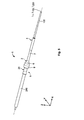
Fig. 1 is a schematic perspective view of thefibre fixation assembly 1, the optical fibre or bundle offibres 100 and theoptical fibre tube 200. Thefibre fixation assembly 1 comprises anadapter 2 forming a housing as well as a sealing for the fibre or bundle offibres 100. A sealingelement 3 of theadapter 2 may sealingly abut an end section orfree end 201 of thetube 200. Further, thefibre fixation assembly 1 comprises a sealing element 4 (Fig. 2 ) for sealing and fixing the fibre or bundle offibres 100 with respect to theadapter 2. - The
adapter 2 comprises atube holding section 5 at a proximal end PE of the adapter, areduction section 6, and afibre holding section 7 at a distal end DE. Thetube holding section 5 is connected to thefibre holding section 7 via thereduction section 6. Thereduction section 6 may have a frustoconical shape to provide a transition between thetube holding section 5 and thefibre holding section 7, wherein thetube holding section 5 has a larger diameter than thefibre holding section 7. - In order to facilitate handling the
fibre fixation assembly 1, ahandling section 8 may provide a handling surface 8' at its perimeter. The handling section 8' may comprise longitudinal ribs at a peripheral surface. Thehandling section 8 may further have an enlarged diameter with respect to thetube holding section 5 and thefibre holding section 7 to improve ergonomy. It is arranged preferably between thetube holding section 5 and thereduction section 6. - Longitudinal axes L1, L100 and L200 of the
fibre fixation assembly 1, the fibre or bundle offibres 100 and thetube 200, respectively, extend essentially in parallel to a longitudinal direction X of thefibre fixation assembly 1. A lateral direction Y of thefibre fixation assembly 1 extends perpendicularly to the longitudinal direction. A height direction Z of the fibre fixation assembly extends perpendicularly to the longitudinal direction X and the lateral direction Y. A fibre direction F of the fibre or bundle offibres 100 extends parallel to the longitudinal direction X in the region of the fixingarrangement 1 and preferably coincides with the longitudinal axes L1, L100 and L200.. Thefibre fixation assembly 1, the fibre or bundle offibres 100 and thetube 200 are arranged coaxially e.g. with respect to the fibre direction F. -
Fig. 2 is a schematic cross-sectional view of thefibre fixation assembly 1, the optical fibre or bundle offibres 100 and thetube 200 along their respective longitudinal axes L1, L100 and L200. The fibre or bundle offibres 100 is guided within aninner space 202 of thetube 200. At theend section 201, thetube 200 is connected to theadapter 2 via theholding section 5 of theadapter 2 extending therefrom against the longitudinal direction X. For this, thetube holding section 5 may comprise e.g. a connectingsection 9 providing a tube-like protrusion or shape that extends in a direction along the fibre direction pointing away from the distal end DE or thefibre holding section 7, respectively. - The connecting
section 9 may be provided with at least one connectingelement 10. The at least one connectingelement 10 is adapted to establish an axial immobilization of thetube 200 and theadapter 2 relative to each other. The connectingelement 10 may provide a positive lock to thetube 200. As shown inFig. 2 it may be formed as a cutting screw-thread 10. The cutting screw-thread cuts into aninner wall 203 of thetube 200. Thereby, the connectingsection 9 meshes with thetube 200 such that both overlap in the longitudinal direction X. - The sealing
element 3 having e.g. the form of a sealing ring encloses theconnection section 9 and is seated between theend section 201 of the tube and the remainingadapter 2. Thereby, the sealingelement 3 seals up a gap between thetube 200 and theadapter 2 in order to prevent any harmful substances from entering or coming out of the tube. An inner space orreceptacle 204 of the adapter, in which the fibre is accommodated, is thus closed at the proximal end of theadapter 2 against the environment. At the distal den DE, thereceptacle 204 terminates in an opening 205. - When entering the connecting
section 9, the fibre or bundle offibres 100 is guided within thereceptacle 204 of thefibre fixation assembly 1. Thereceptacle 204 essentially has a constant diameter di,11 from the proximal end PE to the distal end DE. An outer diameter do,9 (Fig. 4a ) of the connecting section may be smaller than an outer diameter do,5 of thetube holding section 5. At thereduction section 6, the outer diameter do,8 of thehandling section 8 tapers to the smaller outer diameter do,7 of thefibre holding section 7. - As shown in
Fig. 1 , thesealing component 4 may be located in thereceptacle 204 and extend essentially along thefibre holding section 7 up or close to the opening 205. Thesealing component 4 may be a plastically deformable glue such as mastic. Thesealing component 4 seals thereceptacle 204 of theadapter 2 against the outer environment of theadapter 2. Thesealing component 4 is plastically deformed about the fibre or bundle offibres 100 and therefore tightly engages anouter surface 101 of the fibre or bundle offibres 100. Additionally, the sealing component provides mechanical stability in that it provides a strain relief and supports forces acting on the fibre in parallel to the longitudinal direction X. For this, thesealing component 4 is connected to anouter surface 101 over a specified length l4 of about 10 mm to 60 mm, preferably close to 30 mm. -
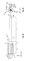
Fig. 3a is schematic side view of thefibre fixation assembly 1, the fibre or bundle offibres 100 and thetube 200. As can be seen, thefibre holding section 7 is provided with ashaft portion 12. In theshaft portion 12, thefibre holding section 7 is enforced by having an increased wall thickness as compared to the remainingfibre holding section 7. Thus, any forces as well as torsional and turning movements acting between thefibre holding section 7 and thereduction section 6 may be transferred therebetween safely without damaging theadapter 2. As an additional effect, the diameter change between theshaft portion 12 and the rest of thefibre holding section 7 provides an edge on which a tool (not shown) may be supported for example. -
Fig. 3b is a schematic front view of thefibre fixation assembly 1 and the fibre or bundle offibres 100. As can be seen, thefibre holding section 7 has an inner diameter dl,7 and an outer diameter dO,7. Theshaft portion 12 has an outer diameter dO,12. Thehandling section 8 has an outer diameter dO,8. -
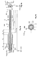
Fig. 4a is schematic cross-sectional view of thefibre fixation assembly 1, the fibre or bundle offibres 100 and thetube 200 along the cross-sectional line A-A depicted inFig. 3a . Here it becomes apparent that the connectingelements 10 are in mesh with theinner wall 203 of thetube 200. Hence, an inner diameter dl,200 of thetube 200 is smaller or at a maximum equals an outer diameter dO,9 of the connectingsection 9. A diameter d100 of the fibre or bundle offibres 100 is smaller than a diameter d204 of thereceptacle 204. The diameter d204 is preferably equal to the inner diameter dl,7 of thefibre holding section 7. In order to prevent the fibre from cracking or kinking when entering theadapter 2 at the connectingsection 9, the connectingsection 9 is provided with abevel 14, pointing to thetube 200, i.e. away from the distal end DE. - A length l5 of the fibre
tube holding section 5, a length l8 of thehandling section 8, a length l6 of thereduction section 6 and a length l7 of the fibre holding section essentially all measured in parallel to the length direction X add up to an overall length l2 of theadapter 2 which essentially equals an overall length l1 of thefibre fixation assembly 1. Theshaft portion 12 has as a length l12 also measured essentially in parallel to the length direction X. A length l4 of the portion of thefibre holding section 7 where thecompound 4 is effective may nearly have a length l7 of thefibre holding section 7, but may also be smaller or exceed the length l7. A sufficiently long length l4 of thesealing component 4 measured essentially in parallel to the length direction X provides a good sealing, support and strain relief of the fibre or bundle offibres 100 within thefibre holding section 7. Thereby, the fibre or bundle offibres 100 and thefibre holding section 7 may act jointly as a stable structure. This is especially the case, when thefibre holding section 7 has a tubular shape as shown herein. -
Fig. 4b is a schematic rear view of thefibre fixation assembly 1 and thetube 200 encompassing the fibre or bundle offibres 100. As can be seen, an outer diameter dO,200 of thetube 200 is smaller than an outer diameter dO,3 of the sealingelement 3 which is in turn slightly smaller than the outer diameter dO,8 of thehandling section 8. Thereby, the sealingelement 3 reliably blocks the entry or exit of water and gas into or out of thetube 200 and thereceptacle 204. - As shown in
Fig. 4a , thefibre holding section 7 comprises asection 13, which is plastically deformed about the fibre or bundle offibres 100. Thedeformed section 13 is located within theshaft section 12 and preferably continuously extends over a specified length l13. As shown inFig 4a , the length and location of thedeformed section 13 correspond to the extent and location of thesealing component 4. -
Fig. 4c schematically shows the cross-section of the deformed section indicated by cross-sectional line B-B inFig. 4a . - In
Fig. 4c , the shape of thefibre holding section 7 or theshaft section 12 prior to the deformation is indicated by a dash-dotted line. By the plastic deformation, which may be effected by a crimping process, the fibre holding section is deformed, such that thecross-sectional area 102 in a plane perpendicular to the fibre direction F is reduced. Thesealing component 4, which is located between the fibre or bundle offibres 100 and thefibre holding section 7, is, at least in parts of the cross-sectional area, compressed and pressed against theouter surface 101 of the fibre or bundle offibres 100 thereby establishing a strong sealing and fixational connection between the sealingcomponent 4 and the fibre or bundle offibres 100. In this embodiment, the plastic deformation of thesealing component 4 is effected and supported by the plastic deformation of thefibre holding section 7 or theshaft section 12, respectively. - Further, by compressing the
sealing component 4 at least in parts of the cross-sectional area, thesealing component 4 is forced to flow into regions, where the compression is weaker. - The hexagonal shape of the
fibre holding section 7 after the plastic deformation is given only by way of example. Other shapes are of course possible, such as polygonal shapes or rounded shapes, such as elliptical or rounded polygons. -
Fig. 5 shows a schematic perspective view of thefibre fixation assembly 1 according to another embodiment of the present invention with the fibre or bundle offibres 100 and thetube 200 immobilized with respect to another thereby. Thefibre fixation assembly 1 comprises theadapter 2. - The
adapter 2 includes thetube holding section 5, thehandling section 8, thereduction section 6, and thefibre holding section 7. The connectingsection 9 in the embodiment ofFig. 5 is a separate, exchangeable, preferably tubular part, such as abushing 20. It protrudes against in the direction pointing away from the distal end DE along the fibre direction. -
Fig. 6 shows thefibre fixation assembly 1 in a schematic side view. Thebushing 20 comprises atube receiving section 21 providing a taperedsection 21 a for inserting the tube into thebushing 20. Aninsertion section 22 of thebushing 20 opposite to the taperedsection 21 a is inserted into areceptacle 23 or theadapter 2. -
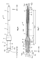
Fig. 7 shows thefibre fixation assembly 1 in a schematic cross-sectional view along the cross-sectional line C-C depicted inFig. 6 . This cross-section is made along a longitudinal axis L1, L2, L20, L100, and L200 of thefibre fixation assembly 1, theadapter 2, thebushing 20, the fibre or bundle offibres 100, and thetube 200, respectively, which are arranged coaxially. A combined length l8, 6,7 of theadapter 2 results from the length l8 of thehandling section 8, the length l6 of thereduction section 6, and the length l7 of thefibre holding section 7. In other words, the lengths l8, l6, and l7 sum up to the combined length l5, 6, 7. A ratio rl8, 6, 7/do,5 between the combined length l8, 6,7 and the outer diameter do, 5 may be between 6 and 8, for example. -
Connecting elements 10 establish a fixation of the exchangeable connectingsection 9 to thetube 200. The connecting elements may have the form of ribs and/or cutter knives that extend essentially along the longitudinal axis L20 of thebushing 20 e.g. at aninner circumference 24. Thebushing 20 is inserted into a part of thetube holding section 5, which opens along the fibre direction F facing away from the distal end DE. - At the
receptacle 23, fixingelements 25 may be provided to engage thebushing 20 and, if necessary, a correspondinglysized tube 200. The connectingelements 10 may have the shape of bars and/or cutter knives which extend essentially along the longitudinal axis L20 of thebushing 20. The fixingelements 25 provide that the connectingsection 9 is in mesh with the remainingadapter 2 and both are mounted to each other by positive fit, force fit, and/or frictional fit. - At or close to the distal end DE, the
fibre holding section 7 may be provided with fixingelements 15 e.g. in the form of ring-shaped ribs extending along an outer circumference of the fibre holding section. The fixingelements 15 enhance a tight fit of thesealing component 4 around thefibre holding section 7. Thesealing component 4 may be , in this embodiment, a heat-shrinking tube or hose which snugly fits around thefibre holding section 7 and the fibre or bundle offibres 100. - The
tube holding section 5 of theadapter 2 has an inner diameter di, 5. The connectingelements 25 within the connectingsection 9 provide that the connectingsection 9 has an inner diameter di, 25 at the connectingelements 25 and otherwise has an inner diameter which essentially equals the inner diameter di, 5 of thetube holding section 5. Theinsertion section 22 of thebushing 20 has an outer diameter do, 22 and an inner diameter di, 22. The connectingelements 10 add to the inner diameter di, 22, such that thebushing 20 narrows at theconnection elements 10. The outer diameter do, 22 of the bushing is larger than or at a maximum equal to the inner diameter di, 25 or, alternatively, to the inner diameter di, 5. - The embodiment shown In
Figs. 5 to 7 allows different connectingsections 9 to be used which are adapted to be connected to a variety of tubes. In order to be exchangeable, theinsertion sections 22 of the various connecting sections are identical so that they all can be integrated into theadapter 2 or thereceptacle 23, respectively. - In this way, the embodiment of
Figs. 5 to 7 differs from the embodiment ofFigs. 1 to 4c , where the whole adapter has to be exchanged, if tubes of various sizes have to be accommodated. Of course, theconnection section 9 of the embodiment shown inFig. 1 may also be a separate, exchangeable part. - In both cases, however, the
various adapters 2 and/or various connectingelements 9 together form a kit which provides identical outer dimensions at least at the fibre holding section, preferably also at the reduction section and the handling section. Thus, theadapter 2 may be handled with a single tool independently of the tube size. - The
elements tube 200, the connectingsection 9 and/or the sealing component to each other as well as to the remainingadapter 2. - The
sealing component 4 may be made of any kind of sealing material, such as mastic, resin, silica gel, or heat-shrinkable material for example, which is suitable for sealing up theadapter 2 and at the same time is sufficiently plastically deformable. Thesealing component 4 may also be comprised of an outer heat-shrinkable tube, covered at the inside with a layer of hotmelt adhesive. A part of thesealing component 4 may already be installed (shrunk) on thefiber holding section 7. The fixingelements 15 helping to keep sealingcomponent 4 in place when a first part is shrunk. Theadapter 2 is thus delivered with thesealing component 4 already attached to it. Once the fiber or fiber bundle has been passed through thefiber holding section 7 and thesealing component 4, the other part of thesealing component 4 can be heated and shrunk to seal the fiber or fiber bundle. When the part of sealingcomponent 4 that is being shrunk in the field, has the appropriate length, the heating can be done with the tool that is already used for the installation of heatshrinkable splice protectors, e.g the length being in the range of 20 mm to 30 mm. - The sealing 3 does not need to have a fixing or immobilizing function. Hence, the sealing may be rather soft such does not need a significant time for hardening.
- In order to assemble the
fibre fixation assembly 1, the following steps are taken: Theadapter 2 is preferably mounted on thetube 200 before the fibre is moved through theadapter 2. For this, theadapter 2 and the tube are connected by thetube holding section 5 in one of the above-described embodiments. If theadapter 2 is provided with an exchangeable connectingsection 9, the proper connectingsection 9 designed for theparticular tube 200 must be chosen first and mounted onto thetube end 201 or the remainingadapter 2. The connection between the tube and the adapter is complete once thetube 200 abuts the sealingelement 3. The fibre or bundle offibres 100 extending out of thetube 200 is inserted into theadapter 2 and moved through the adapter, so that it extends beyond theadapter 2 arranged between the free end of the fibre or bundle offibres 100 and the tube. The fibre or bundle offibres 100 may in particular be moved through theadapter 2 by a gas flow streaming through thetube 200 and the receptacle of theadapter 2 thereby moving and centring the fibre. - The
sealing component 4 may be pre-mounted on theadapter 2 before the fibre or bundle offibres 100 is threaded through the sealing component. - When the fibre has reached the desired position relative to the adapter, the sealing component is plastically deformed about the fibre and brought into contact with the fibre surface to establish a sealing connection between the
fibre holding section 5 and the fibre or bundle offibres 100 and to shield the receptacle of theadapter 2 against environmental contamination. - In the above-shown embodiments, the deformation may take place by deforming, e.g. crimping, the fibre holding element in a region in which the sealing component is applied. Additionally or alternatively, heat may be applied to plastically deform, in particular, shrink the sealing component and/or the fibre holding section.
- Once the fibre or fibre bundle, the sealing component and the fibre holding section have been brought into sealing contact with one another, the installation of the
adapter 2 is complete.
Claims (15)
- Adapter (2) for fixing an optical fibre or bundle of optical fibres (100), with respect to an end section (201) of a tube (200) accommodating the fibre or fibre bundle (100), comprising:a tube holding section (5) at a proximal end (PE) of the adapter (2),the tube holding section being adapted to fix the adapter (2) to the tube,a fibre holding section (7) providing a substantially tubular receptacle (204) for receiving the fibre or bundle of fibres (100),the receptacle (204) having a distal opening (205) at a distal end (DE) of the adapter (2), and a sealing component (4),characterized in that the sealing component (4) is plastically deformable for fixing the fibre or bundle of fibres (100) to the adapter (2).
- Adapter (2) according to claim 1, wherein the fibre holding section (7) is adapted to be at least partially, plastically deformed about the fibre or bundle of fibres (100).
- Adapter (2) according to claim 1 or 2, wherein the sealing component (4) comprises heatshrinkable tubing.
- Adapter (2) according to any one of claims 1 to 3, wherein the distal end (DE) of the fibre holding section (7) is received within the sealing component (4).
- Adapter (2) according to any one of claims 1 to 4, wherein the sealing component (4) comprises a glue material.
- Adapter (2) according to any one of claims 1 to 5, wherein the fibre holding section (7) comprises at least one fixing element (15) facing the sealing component (4) and adapted to be positively locked to the sealing component.
- Adapter (2) according to any one of claims 1 to 6, wherein a diameter (dO,7) of a part of the fibre holding section (7), the part being engaged by the sealing component (4), does not exceed five times a diameter of the fibre or bundle of fibres (100).
- Adapter (2) according to any one of claims 1 to 7, wherein a length, over which the sealing component (4) is adapted to be engaged to the fibre or bundle of fibres (100) is at least 10 times a diameter (d100) of the fibre or bundle of fibres (100).
- Adapter (2) according to any one of claims 1 to 8, wherein the tube holding section (5) is provided with a connecting element (10), the connecting element (10) being adapted to mesh with a wall (203) of the tube (200).
- Adapter (2) according to any one of claims 1 to 9, wherein the tube holding section (5) has an outer diameter (do,9) which exceeds an inner diameter (di,200) of the tube (200).
- Adapter (2) according to any one of claims 1 to 10, wherein a reduction section (6) is arranged between the tube holding section (5) and the fibre holding section (7), the reduction section (6) having an outer shape that tapers towards the fibre holding section (7).
- Adapter (2) according to any one of claims 1 to 11, wherein the tube holding section (5) comprises an inner circumference of the bushing (20) is provided with at least one fixing element (23) which is adapted to mesh with an outer wall (203) of the tube (200).
- Adapter (2) according to claim 12, characterised in that the at least one fixing element (23) is formed as a cutter knife which extends essentially in parallel to the fibre direction (F) of the fixing arrangement (1).
- Adapter (2) according to one of claims 1 to 13, wherein a sealing element (3) is provided at the proximal end (PE), the sealing element being adapted to be sealingly arranged between the tube (200) and the adapter (2).
- Method for fixing an optical fibre or bundle of fibres (100) extending in a fibre direction (F) with respect to an end section (201) of a tube (200) accommodating the fibre or bundle of fibres (100), the method including the steps of:fixing an adapter (2) to the end section (201),inserting a fibre or bundle of optical fibres (100) through the adapter (2),inserting the fibre or bundle of optical fibres (100) through a sealing component (4),bringing the sealing component (4) into sealing and holding engagement with the adapter (2), andplastically deforming the sealing component (4) about the fibre or bundle of optical fibres (100) to bring the sealing component (4) into sealing and holding engagement with the fibre or bundle of fibres (100).
Priority Applications (4)
| Application Number | Priority Date | Filing Date | Title |
|---|---|---|---|
| EP11164939.8A EP2520961B1 (en) | 2011-05-05 | 2011-05-05 | Adapter and method for fixing an optical fibre to the end of a tube |
| ES11164939.8T ES2625448T3 (en) | 2011-05-05 | 2011-05-05 | Adapter and method for attaching an optical fiber to the end of a tube |
| EP17159080.5A EP3190442B1 (en) | 2011-05-05 | 2011-05-05 | Adapter and method for fixing an optical fibre to the end of a tube |
| DK17159080.5T DK3190442T3 (en) | 2011-05-05 | 2011-05-05 | ADAPTER AND METHOD FOR ATTACHING AN OPTICAL FIBER TO THE END OF A TUBE |
Applications Claiming Priority (1)
| Application Number | Priority Date | Filing Date | Title |
|---|---|---|---|
| EP11164939.8A EP2520961B1 (en) | 2011-05-05 | 2011-05-05 | Adapter and method for fixing an optical fibre to the end of a tube |
Related Child Applications (1)
| Application Number | Title | Priority Date | Filing Date |
|---|---|---|---|
| EP17159080.5A Division EP3190442B1 (en) | 2011-05-05 | 2011-05-05 | Adapter and method for fixing an optical fibre to the end of a tube |
Publications (2)
| Publication Number | Publication Date |
|---|---|
| EP2520961A1 true EP2520961A1 (en) | 2012-11-07 |
| EP2520961B1 EP2520961B1 (en) | 2017-03-08 |
Family
ID=44749593
Family Applications (2)
| Application Number | Title | Priority Date | Filing Date |
|---|---|---|---|
| EP11164939.8A Active EP2520961B1 (en) | 2011-05-05 | 2011-05-05 | Adapter and method for fixing an optical fibre to the end of a tube |
| EP17159080.5A Active EP3190442B1 (en) | 2011-05-05 | 2011-05-05 | Adapter and method for fixing an optical fibre to the end of a tube |
Family Applications After (1)
| Application Number | Title | Priority Date | Filing Date |
|---|---|---|---|
| EP17159080.5A Active EP3190442B1 (en) | 2011-05-05 | 2011-05-05 | Adapter and method for fixing an optical fibre to the end of a tube |
Country Status (3)
| Country | Link |
|---|---|
| EP (2) | EP2520961B1 (en) |
| DK (1) | DK3190442T3 (en) |
| ES (1) | ES2625448T3 (en) |
Citations (4)
| Publication number | Priority date | Publication date | Assignee | Title |
|---|---|---|---|---|
| US4615031A (en) * | 1982-07-27 | 1986-09-30 | International Standard Electric Corporation | Injection laser packages |
| US5903693A (en) * | 1997-09-30 | 1999-05-11 | The United States Of America As Represented By The Secretary Of The Navy | Fiber optic cable furcation unit |
| US6322751B1 (en) * | 1998-02-02 | 2001-11-27 | Scott Russell Burge | Optrode for the detection of volatile chemicals |
| GB2450806A (en) * | 2007-07-06 | 2009-01-07 | Weatherford Lamb | Termination of fibre optic cable |
-
2011
- 2011-05-05 ES ES11164939.8T patent/ES2625448T3/en active Active
- 2011-05-05 DK DK17159080.5T patent/DK3190442T3/en active
- 2011-05-05 EP EP11164939.8A patent/EP2520961B1/en active Active
- 2011-05-05 EP EP17159080.5A patent/EP3190442B1/en active Active
Patent Citations (4)
| Publication number | Priority date | Publication date | Assignee | Title |
|---|---|---|---|---|
| US4615031A (en) * | 1982-07-27 | 1986-09-30 | International Standard Electric Corporation | Injection laser packages |
| US5903693A (en) * | 1997-09-30 | 1999-05-11 | The United States Of America As Represented By The Secretary Of The Navy | Fiber optic cable furcation unit |
| US6322751B1 (en) * | 1998-02-02 | 2001-11-27 | Scott Russell Burge | Optrode for the detection of volatile chemicals |
| GB2450806A (en) * | 2007-07-06 | 2009-01-07 | Weatherford Lamb | Termination of fibre optic cable |
Also Published As
| Publication number | Publication date |
|---|---|
| EP3190442B1 (en) | 2021-12-29 |
| ES2625448T3 (en) | 2017-07-19 |
| EP3190442A1 (en) | 2017-07-12 |
| DK3190442T3 (en) | 2022-03-28 |
| EP2520961B1 (en) | 2017-03-08 |
Similar Documents
| Publication | Publication Date | Title |
|---|---|---|
| US10036859B2 (en) | Cable termination assembly and method for connectors | |
| CN109477943B (en) | Optical Termination Package with Reinforced Self-Supporting Tether | |
| US7703990B1 (en) | Furcation bodies and fiber optic assemblies using the same | |
| EP2184631B1 (en) | Self healing optical fiber cable assembly and method for making the same | |
| US4728171A (en) | System for use in temporary repair of multiple fiber cable | |
| US20170336576A1 (en) | Field installed optical fiber connector for jacketed fiber cable and termination method | |
| EP0244225B1 (en) | Optic fiber connector | |
| CN106461879A (en) | Fiber optic cable assemblies for terminating a fiber optic cable and methods of making the same | |
| JP2005516237A (en) | Fiber optic tube sealing | |
| US11360265B2 (en) | Fiber optic cable assembly with overlapping bundled strength members, and fabrication method and apparatus | |
| AU2009223230B2 (en) | Method of attachment of a connector to a fiber optic cable | |
| EP3511752B1 (en) | Splice closure and method for installing optical cable | |
| US9069152B2 (en) | Furcating fiber optic cables without direct coupling of optical fibers to strength members, and related assemblies and methods | |
| EP3190442B1 (en) | Adapter and method for fixing an optical fibre to the end of a tube | |
| EP3978971A1 (en) | Coating fusion spliced optical fibers and subsequent processing methods thereof | |
| WO2012113809A1 (en) | Air blown optical fibre fixation | |
| US20100046904A1 (en) | Adapter for sleeves with elastomer cable seals and method for introducing a fiber-optic cable into a sleeve | |
| AU2010313617A1 (en) | Method for fastening a fiber optic connector to a fiber optic cable | |
| EP1493046B1 (en) | Flexible optic fiber cable with centered, interference fit ferrules | |
| RU2771064C1 (en) | Method for securing optic fibres in a modular tube | |
| EP2743745A1 (en) | Field-installable optical splice | |
| SE506173C2 (en) | Lubricant application device |
Legal Events
| Date | Code | Title | Description |
|---|---|---|---|
| PUAI | Public reference made under article 153(3) epc to a published international application that has entered the european phase |
Free format text: ORIGINAL CODE: 0009012 |
|
| AK | Designated contracting states |
Kind code of ref document: A1 Designated state(s): AL AT BE BG CH CY CZ DE DK EE ES FI FR GB GR HR HU IE IS IT LI LT LU LV MC MK MT NL NO PL PT RO RS SE SI SK SM TR |
|
| AX | Request for extension of the european patent |
Extension state: BA ME |
|
| 17P | Request for examination filed |
Effective date: 20130507 |
|
| 17Q | First examination report despatched |
Effective date: 20141112 |
|
| GRAP | Despatch of communication of intention to grant a patent |
Free format text: ORIGINAL CODE: EPIDOSNIGR1 |
|
| INTG | Intention to grant announced |
Effective date: 20160914 |
|
| STAA | Information on the status of an ep patent application or granted ep patent |
Free format text: STATUS: GRANT OF PATENT IS INTENDED |
|
| GRAS | Grant fee paid |
Free format text: ORIGINAL CODE: EPIDOSNIGR3 |
|
| GRAA | (expected) grant |
Free format text: ORIGINAL CODE: 0009210 |
|
| STAA | Information on the status of an ep patent application or granted ep patent |
Free format text: STATUS: THE PATENT HAS BEEN GRANTED |
|
| AK | Designated contracting states |
Kind code of ref document: B1 Designated state(s): AL AT BE BG CH CY CZ DE DK EE ES FI FR GB GR HR HU IE IS IT LI LT LU LV MC MK MT NL NO PL PT RO RS SE SI SK SM TR |
|
| RAP1 | Party data changed (applicant data changed or rights of an application transferred) |
Owner name: COMMSCOPE CONNECTIVITY BELGIUM BVBA |
|
| REG | Reference to a national code |
Ref country code: GB Ref legal event code: FG4D |
|
| REG | Reference to a national code |
Ref country code: CH Ref legal event code: EP Ref country code: AT Ref legal event code: REF Ref document number: 874040 Country of ref document: AT Kind code of ref document: T Effective date: 20170315 |
|
| REG | Reference to a national code |
Ref country code: IE Ref legal event code: FG4D |
|
| REG | Reference to a national code |
Ref country code: DE Ref legal event code: R096 Ref document number: 602011035629 Country of ref document: DE |
|
| REG | Reference to a national code |
Ref country code: FR Ref legal event code: PLFP Year of fee payment: 7 |
|
| REG | Reference to a national code |
Ref country code: LT Ref legal event code: MG4D |
|
| REG | Reference to a national code |
Ref country code: NL Ref legal event code: MP Effective date: 20170308 |
|
| REG | Reference to a national code |
Ref country code: ES Ref legal event code: FG2A Ref document number: 2625448 Country of ref document: ES Kind code of ref document: T3 Effective date: 20170719 |
|
| PG25 | Lapsed in a contracting state [announced via postgrant information from national office to epo] |
Ref country code: LT Free format text: LAPSE BECAUSE OF FAILURE TO SUBMIT A TRANSLATION OF THE DESCRIPTION OR TO PAY THE FEE WITHIN THE PRESCRIBED TIME-LIMIT Effective date: 20170308 Ref country code: GR Free format text: LAPSE BECAUSE OF FAILURE TO SUBMIT A TRANSLATION OF THE DESCRIPTION OR TO PAY THE FEE WITHIN THE PRESCRIBED TIME-LIMIT Effective date: 20170609 Ref country code: HR Free format text: LAPSE BECAUSE OF FAILURE TO SUBMIT A TRANSLATION OF THE DESCRIPTION OR TO PAY THE FEE WITHIN THE PRESCRIBED TIME-LIMIT Effective date: 20170308 Ref country code: FI Free format text: LAPSE BECAUSE OF FAILURE TO SUBMIT A TRANSLATION OF THE DESCRIPTION OR TO PAY THE FEE WITHIN THE PRESCRIBED TIME-LIMIT Effective date: 20170308 Ref country code: NO Free format text: LAPSE BECAUSE OF FAILURE TO SUBMIT A TRANSLATION OF THE DESCRIPTION OR TO PAY THE FEE WITHIN THE PRESCRIBED TIME-LIMIT Effective date: 20170608 |
|
| REG | Reference to a national code |
Ref country code: AT Ref legal event code: MK05 Ref document number: 874040 Country of ref document: AT Kind code of ref document: T Effective date: 20170308 |
|
| PG25 | Lapsed in a contracting state [announced via postgrant information from national office to epo] |
Ref country code: LU Free format text: LAPSE BECAUSE OF NON-PAYMENT OF DUE FEES Effective date: 20170531 Ref country code: LV Free format text: LAPSE BECAUSE OF FAILURE TO SUBMIT A TRANSLATION OF THE DESCRIPTION OR TO PAY THE FEE WITHIN THE PRESCRIBED TIME-LIMIT Effective date: 20170308 Ref country code: RS Free format text: LAPSE BECAUSE OF FAILURE TO SUBMIT A TRANSLATION OF THE DESCRIPTION OR TO PAY THE FEE WITHIN THE PRESCRIBED TIME-LIMIT Effective date: 20170308 Ref country code: BG Free format text: LAPSE BECAUSE OF FAILURE TO SUBMIT A TRANSLATION OF THE DESCRIPTION OR TO PAY THE FEE WITHIN THE PRESCRIBED TIME-LIMIT Effective date: 20170608 Ref country code: SE Free format text: LAPSE BECAUSE OF FAILURE TO SUBMIT A TRANSLATION OF THE DESCRIPTION OR TO PAY THE FEE WITHIN THE PRESCRIBED TIME-LIMIT Effective date: 20170308 |
|
| PG25 | Lapsed in a contracting state [announced via postgrant information from national office to epo] |
Ref country code: NL Free format text: LAPSE BECAUSE OF FAILURE TO SUBMIT A TRANSLATION OF THE DESCRIPTION OR TO PAY THE FEE WITHIN THE PRESCRIBED TIME-LIMIT Effective date: 20170308 |
|
| PG25 | Lapsed in a contracting state [announced via postgrant information from national office to epo] |
Ref country code: AT Free format text: LAPSE BECAUSE OF FAILURE TO SUBMIT A TRANSLATION OF THE DESCRIPTION OR TO PAY THE FEE WITHIN THE PRESCRIBED TIME-LIMIT Effective date: 20170308 Ref country code: SK Free format text: LAPSE BECAUSE OF FAILURE TO SUBMIT A TRANSLATION OF THE DESCRIPTION OR TO PAY THE FEE WITHIN THE PRESCRIBED TIME-LIMIT Effective date: 20170308 Ref country code: CZ Free format text: LAPSE BECAUSE OF FAILURE TO SUBMIT A TRANSLATION OF THE DESCRIPTION OR TO PAY THE FEE WITHIN THE PRESCRIBED TIME-LIMIT Effective date: 20170308 Ref country code: EE Free format text: LAPSE BECAUSE OF FAILURE TO SUBMIT A TRANSLATION OF THE DESCRIPTION OR TO PAY THE FEE WITHIN THE PRESCRIBED TIME-LIMIT Effective date: 20170308 Ref country code: RO Free format text: LAPSE BECAUSE OF FAILURE TO SUBMIT A TRANSLATION OF THE DESCRIPTION OR TO PAY THE FEE WITHIN THE PRESCRIBED TIME-LIMIT Effective date: 20170308 |
|
| PG25 | Lapsed in a contracting state [announced via postgrant information from national office to epo] |
Ref country code: SM Free format text: LAPSE BECAUSE OF FAILURE TO SUBMIT A TRANSLATION OF THE DESCRIPTION OR TO PAY THE FEE WITHIN THE PRESCRIBED TIME-LIMIT Effective date: 20170308 Ref country code: PL Free format text: LAPSE BECAUSE OF FAILURE TO SUBMIT A TRANSLATION OF THE DESCRIPTION OR TO PAY THE FEE WITHIN THE PRESCRIBED TIME-LIMIT Effective date: 20170308 Ref country code: IS Free format text: LAPSE BECAUSE OF FAILURE TO SUBMIT A TRANSLATION OF THE DESCRIPTION OR TO PAY THE FEE WITHIN THE PRESCRIBED TIME-LIMIT Effective date: 20170708 Ref country code: PT Free format text: LAPSE BECAUSE OF FAILURE TO SUBMIT A TRANSLATION OF THE DESCRIPTION OR TO PAY THE FEE WITHIN THE PRESCRIBED TIME-LIMIT Effective date: 20170710 |
|
| REG | Reference to a national code |
Ref country code: DE Ref legal event code: R097 Ref document number: 602011035629 Country of ref document: DE |
|
| REG | Reference to a national code |
Ref country code: CH Ref legal event code: PL |
|
| PLBE | No opposition filed within time limit |
Free format text: ORIGINAL CODE: 0009261 |
|
| STAA | Information on the status of an ep patent application or granted ep patent |
Free format text: STATUS: NO OPPOSITION FILED WITHIN TIME LIMIT |
|
| PG25 | Lapsed in a contracting state [announced via postgrant information from national office to epo] |
Ref country code: DK Free format text: LAPSE BECAUSE OF FAILURE TO SUBMIT A TRANSLATION OF THE DESCRIPTION OR TO PAY THE FEE WITHIN THE PRESCRIBED TIME-LIMIT Effective date: 20170308 Ref country code: MC Free format text: LAPSE BECAUSE OF FAILURE TO SUBMIT A TRANSLATION OF THE DESCRIPTION OR TO PAY THE FEE WITHIN THE PRESCRIBED TIME-LIMIT Effective date: 20170308 |
|
| 26N | No opposition filed |
Effective date: 20171211 |
|
| REG | Reference to a national code |
Ref country code: IE Ref legal event code: MM4A |
|
| PG25 | Lapsed in a contracting state [announced via postgrant information from national office to epo] |
Ref country code: LI Free format text: LAPSE BECAUSE OF NON-PAYMENT OF DUE FEES Effective date: 20170531 Ref country code: SI Free format text: LAPSE BECAUSE OF FAILURE TO SUBMIT A TRANSLATION OF THE DESCRIPTION OR TO PAY THE FEE WITHIN THE PRESCRIBED TIME-LIMIT Effective date: 20170308 Ref country code: CH Free format text: LAPSE BECAUSE OF NON-PAYMENT OF DUE FEES Effective date: 20170531 |
|
| PG25 | Lapsed in a contracting state [announced via postgrant information from national office to epo] |
Ref country code: LU Free format text: LAPSE BECAUSE OF NON-PAYMENT OF DUE FEES Effective date: 20170505 |
|
| REG | Reference to a national code |
Ref country code: BE Ref legal event code: MM Effective date: 20170531 |
|
| PG25 | Lapsed in a contracting state [announced via postgrant information from national office to epo] |
Ref country code: IE Free format text: LAPSE BECAUSE OF NON-PAYMENT OF DUE FEES Effective date: 20170505 |
|
| REG | Reference to a national code |
Ref country code: FR Ref legal event code: PLFP Year of fee payment: 8 |
|
| PGFP | Annual fee paid to national office [announced via postgrant information from national office to epo] |
Ref country code: ES Payment date: 20180601 Year of fee payment: 8 |
|
| PG25 | Lapsed in a contracting state [announced via postgrant information from national office to epo] |
Ref country code: BE Free format text: LAPSE BECAUSE OF NON-PAYMENT OF DUE FEES Effective date: 20170531 |
|
| PG25 | Lapsed in a contracting state [announced via postgrant information from national office to epo] |
Ref country code: MT Free format text: LAPSE BECAUSE OF NON-PAYMENT OF DUE FEES Effective date: 20170505 |
|
| PG25 | Lapsed in a contracting state [announced via postgrant information from national office to epo] |
Ref country code: HU Free format text: LAPSE BECAUSE OF FAILURE TO SUBMIT A TRANSLATION OF THE DESCRIPTION OR TO PAY THE FEE WITHIN THE PRESCRIBED TIME-LIMIT; INVALID AB INITIO Effective date: 20110505 |
|
| PG25 | Lapsed in a contracting state [announced via postgrant information from national office to epo] |
Ref country code: CY Free format text: LAPSE BECAUSE OF NON-PAYMENT OF DUE FEES Effective date: 20170308 |
|
| PG25 | Lapsed in a contracting state [announced via postgrant information from national office to epo] |
Ref country code: MK Free format text: LAPSE BECAUSE OF FAILURE TO SUBMIT A TRANSLATION OF THE DESCRIPTION OR TO PAY THE FEE WITHIN THE PRESCRIBED TIME-LIMIT Effective date: 20170308 |
|
| PG25 | Lapsed in a contracting state [announced via postgrant information from national office to epo] |
Ref country code: TR Free format text: LAPSE BECAUSE OF FAILURE TO SUBMIT A TRANSLATION OF THE DESCRIPTION OR TO PAY THE FEE WITHIN THE PRESCRIBED TIME-LIMIT Effective date: 20170308 |
|
| PG25 | Lapsed in a contracting state [announced via postgrant information from national office to epo] |
Ref country code: AL Free format text: LAPSE BECAUSE OF FAILURE TO SUBMIT A TRANSLATION OF THE DESCRIPTION OR TO PAY THE FEE WITHIN THE PRESCRIBED TIME-LIMIT Effective date: 20170308 |
|
| PGFP | Annual fee paid to national office [announced via postgrant information from national office to epo] |
Ref country code: FR Payment date: 20200525 Year of fee payment: 10 |
|
| PGFP | Annual fee paid to national office [announced via postgrant information from national office to epo] |
Ref country code: IT Payment date: 20200522 Year of fee payment: 10 |
|
| REG | Reference to a national code |
Ref country code: ES Ref legal event code: FD2A Effective date: 20200925 |
|
| PG25 | Lapsed in a contracting state [announced via postgrant information from national office to epo] |
Ref country code: ES Free format text: LAPSE BECAUSE OF NON-PAYMENT OF DUE FEES Effective date: 20190506 |
|
| PG25 | Lapsed in a contracting state [announced via postgrant information from national office to epo] |
Ref country code: FR Free format text: LAPSE BECAUSE OF NON-PAYMENT OF DUE FEES Effective date: 20210531 |
|
| PG25 | Lapsed in a contracting state [announced via postgrant information from national office to epo] |
Ref country code: IT Free format text: LAPSE BECAUSE OF NON-PAYMENT OF DUE FEES Effective date: 20200505 |
|
| P01 | Opt-out of the competence of the unified patent court (upc) registered |
Effective date: 20230530 |
|
| PGFP | Annual fee paid to national office [announced via postgrant information from national office to epo] |
Ref country code: GB Payment date: 20230529 Year of fee payment: 13 |
|
| GBPC | Gb: european patent ceased through non-payment of renewal fee |
Effective date: 20240505 |
|
| PG25 | Lapsed in a contracting state [announced via postgrant information from national office to epo] |
Ref country code: GB Free format text: LAPSE BECAUSE OF NON-PAYMENT OF DUE FEES Effective date: 20240505 |
|
| PGFP | Annual fee paid to national office [announced via postgrant information from national office to epo] |
Ref country code: DE Payment date: 20250529 Year of fee payment: 15 |
|
| PG25 | Lapsed in a contracting state [announced via postgrant information from national office to epo] |
Ref country code: IT Free format text: LAPSE BECAUSE OF NON-PAYMENT OF DUE FEES Effective date: 20210505 |