EP2520489B1 - Geteilter Blatthalterlaufring mit inneren und äußeren Fasen - Google Patents
Geteilter Blatthalterlaufring mit inneren und äußeren Fasen Download PDFInfo
- Publication number
- EP2520489B1 EP2520489B1 EP12166092.2A EP12166092A EP2520489B1 EP 2520489 B1 EP2520489 B1 EP 2520489B1 EP 12166092 A EP12166092 A EP 12166092A EP 2520489 B1 EP2520489 B1 EP 2520489B1
- Authority
- EP
- European Patent Office
- Prior art keywords
- race
- split
- blade
- blade retention
- chamfer
- Prior art date
- Legal status (The legal status is an assumption and is not a legal conclusion. Google has not performed a legal analysis and makes no representation as to the accuracy of the status listed.)
- Active
Links
Images



Classifications
-
- B—PERFORMING OPERATIONS; TRANSPORTING
- B64—AIRCRAFT; AVIATION; COSMONAUTICS
- B64C—AEROPLANES; HELICOPTERS
- B64C11/00—Propellers, e.g. of ducted type; Features common to propellers and rotors for rotorcraft
- B64C11/02—Hub construction
- B64C11/04—Blade mountings
Definitions
- the subject matter disclosed herein relates generally to the field of a split blade retention race for an aircraft propeller blade.
- a propeller for use in an aircraft includes a central rotating hub having a plurality of blade receiving sockets disposed about the hub.
- the propeller blades each have a shank located at the base of each propeller blade, and each shank is disposed in a respective blade receiving socket.
- the blade receiving sockets and the blade shanks are provided with opposed, separated ball bearing race surfaces, and a plurality of balls are held between the blade receiving socket and the blade shank on the race surfaces, allowing adjustment of the pitch of the blade.
- the ball bearing race on the blade shank may be a separate component, referred to as a blade retention race, that encircles the blade shank.
- the blades are shipped with a one piece blade race.
- split blade retention race Due to the movement and loading of the balls on the race surface, and resulting damage that occurs to the race, one piece races may be replaced by split races at overhaul. Such a multisection blade retention race may be referred to as a split blade retention race. Once the one-piece race is replaced by split races, the movement and loading of the balls on the edges of the split races has a tendency to damage the blade shank beyond repair.
- An exemplary split race is disclosed in GB 204,864 .
- the present invention provides a split blade retention race for a blade shank assembly for an aircraft propeller blade according to claim 1.
- Embodiments of a split blade retention race with inner and outer chamfers are provided, with exemplary embodiments being discussed below in detail.
- Current split blade races may have a limited lifespan due to the load from the balls that are held in the race loading the split blade retention race and the geometry of the race at the split.
- Inclusion of chamfers (defined as a straight beveled edge connecting two surfaces) at the split on both the inner surface of the split blade retention race (adjacent to the blade shank) and the outer surface of the split blade retention race (adjacent to the race surface that holds the balls) prevents the balls from loading the unsupported portion at the edge of the split blade retention race at the split.
- a radius connecting the chamfer to the adjacent surface provides a smooth race transition for the balls over the split to prevent damage to the blade shank. This extends the life of the split blade retention race, and reduces the number of propeller blades that need to be scrapped due to damage to the blade shank.
- the chamfers further include associated radii, which are curved surfaces that blend the chamfers to adjacent surfaces on the split blade retention race. The radii provide a smooth transition between the chamfers and the adjacent surfaces.
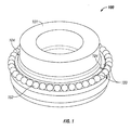
- FIG. 1 shows an embodiment of a blade shank assembly 100 for insertion into a blade receiving socket (not shown) of an aircraft propeller.
- the blade shank assembly 100 includes blade shank 101, balls 102, and split blade retention races 103.
- Splits 104 are located between sections of split blade retention race 103.
- the edges of split blade race 103 at the splits 104 each include a chamfer on the internal side, adjacent to the shank 101, and on the external side, adjacent to the race surface of the split blade retention races 103 on which balls 102 are located.
- the proportions of the internal and external chamfers ensure that the race is not loaded over the unsupported portion at the edges of the inner split blade retention races 103.
- the internal and external radii provide a smooth transition by balls 102 between the chamfers and the adjacent race surfaces on the split blade retention race 103 in order to prevent damage to the blade shank 101 as the balls 102 pass over the splits 104. This helps to reduce damage to the split blade retention race 103 and the blade shank 101 from the balls as they pass over the splits 104.
- the width of the splits 104 are a resultant of the manufacturing process.
- the split blade retention race 103 is manufactured as a complete ring and then cut in half to form splits 104. Manufacturing the split blade retention race 103 as a complete ring before splitting ensures that the race curvatures of both halves of the split blade retention race 103 are identical.
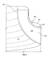
- FIG. 2 shows a top view of the split blade retention race 103 of FIG. 1 .
- the balls 102 move on the race surface of split blade race 103, and pass over splits 104.
- Splits 104 are located between the sections of split blade retention race 103.
- the split blade retention race 103 includes inner chamfers 201, at the edge of the each of the splits 104 on the inner surface of the split blade retention race 103 that is placed adjacent to blade shank 101.
- the split blade retention race 103 also includes outer chamfers 202, located at the edge of the splits 104 on the race surface of the split blade retention race 103 adjacent to the balls 102. The outer chamfers 202 prevent loading from the balls 102 from being transferred to the unsupported section of the split blade retention race 103.
- split configuration of the split blade retention race 103 is such that only one ball of balls 102 is unloaded at any given time; the rest of the balls 102 share the load. This helps to minimize the amount of load carried by each ball.
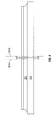
- FIG. 3 shows a side view of a blade shank 101 and a split blade retention race 103 at a split 104.
- Race surface 301 is the surface on which the balls 102 are held.
- Split surface 302 of split blade retention race 103 is located inside a split 104 directly facing a corresponding split surface on another section of the split blade retention race 103 on the other side of the split 104.
- Inner chamfer 201 is angled back from split surface 302 to an inner surface of split blade retention race that is adjacent to the blade shank 101.
- a curved inner radius (discussed in further detail with respect to FIG. 6 ) is associated with inner chamfer 201 to provide a smooth blend between the inner chamfer 201 and the surface of the split blade retention race 103 that is adjacent to blade shank 101.
- Outer chamfer 202 is angled back from split surface 302 to race surface 301 such that there is a dip in the race that holds the balls adjacent to the split 104.
- a curved outer radius 303 (discussed in further detail with respect to FIG. 6 ) is associated with outer chamfer 202 to provide a smooth blend between the outer chamfer 202 and the adjacent race surface 301.
- the inner and outer radii ensure that there are no sharp edges between the chamfers 201/202 and adjacent surfaces, as sharp edges tend to cause damage to both the blade shank 101 and race 103.
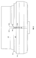
- FIG. 4 shows a side view of a split blade retention race 103 at a split 104.
- the inner chamfers 201, outer chamfers 202, and race surface 301 are also shown.
- Load lines 401a-b located at the edges of the outer radii associated with outer chamfers 202, show the points at which a ball of balls 102 is fully loaded on the race surface 301 of the split blade retention race 103.
- load lines 401a and 401b the inner chamfers 201, outer chamfers 202, and radii ensure that a ball unloads and becomes fully unloaded over the inner unsupported section of the race.
- the chamfers 201/202 are sized such that only one ball of balls 102 is unloaded at a time, and the outer chamfers 202 are larger than the inner chamfers 201.
- FIG. 5 shows a side view of a blade shank 101 with a split blade retention race 103 at a split 104.
- Inner chamfers 201 and outer chamfers 202 are located on split blade retention race 103 at the edges of the split 104.
- Load lines 401 a-b, located at the edges of the outer radii associated with outer chamfers 202, show the point at which a ball is fully loaded on the race surface 301 of the split blade retention race 103.
- the ball becomes unloaded on either split blade retention race 103 due to the presence of outer chamfers 202 and associated outer radii, preventing loading of the unsupported section of the split blade retention race 103.
- Inner chamfers 201 and associated radii are located on the side of the split blade retention race 103 that is adjacent to the blade shank 101.
- FIG. 6 illustrates a detailed view of an embodiment of inner and outer chamfers and associated inner and outer radii.
- Split blade retention race 103 with race surface 301 and balls 102 located on race surface 301, is shown; the split blade retention race 103 is located on blade shank 101.
- Detailed view 600a shows an inner chamfer 201 and associated inner radius 601.
- Inner chamfer 201 is a straight surface
- inner radius 601 is a curved surface joining the inner chamfer 201 to the surface of split blade retention race 103 that is adjacent to blade shank 101.
- the curve of radius 601 prevents damage to the blade shank 101.
- Detailed view 600b shows an outer chamfer 202 and associated outer radius 303.
- Outer chamfer 202 is a straight surface
- outer radius 303 is a curved surface joining the outer chamfer 202 to the race surface 301, ensuring a smooth transition for the balls 102 as the balls 102 pass over the outer chamfers 202 and outer radii 303.
- Load lines 401a-b are located on the outer edges of the outer radii 303.
- Line 603 illustrates the center load line 603 of a ball 102. When the center load line 603 of a ball 102 is between load lines 401a-b, the ball starts to unload then becomes fully unloaded when the depth below the race surface 301 equals the compressive deflection of the ball 102. This is shown in further detail with respect to FIG. 7 .
- the compressive deflection 701 of a ball 102 is shown with respect to cross-section 702 along line A-A'.
- depth below the race surface 301 (on radius or chamfer), indicated by lines 704 equals the compressive deflection 702 of the ball 102, ball 102 is fully unloaded.
- the technical effects and benefits of exemplary embodiments include reduction of blade shank damage due to blade race split configuration as well as reduction in wear in the split race edges.
Landscapes
- Engineering & Computer Science (AREA)
- Aviation & Aerospace Engineering (AREA)
- Rolling Contact Bearings (AREA)
Claims (9)
- Ringförmiger geteilter Blatthalterlaufring (103) für eine Blattschaftbaugruppe (101) für ein Flugzeugpropellerblatt, umfassend:eine radial innere Fläche, wobei die innere Fläche dazu konfiguriert ist, benachbart zu einem Blattschaft in der Blattschaftbaugruppe angeordnet zu sein;eine radial äußere Laufringfläche (301), wobei die Laufringfläche dazu konfiguriert ist, eine Mehrzahl von Kugeln (102) aufzunehmen; undeine geteilte Fläche (104), wobei die geteilte Fläche dazu konfiguriert ist, innerhalb einer radialen Teilung angeordnet zu sein, die einen ersten Abschnitt des geteilten Blatthalterlaufrings von einem zweiten Abschnitt des geteilten Blatthalterlaufrings zu trennen;gekennzeichnet durch:eine innere Fase (201), wobei die innere Fase entlang einer Grenzfläche zwischen der geteilten Fläche und der inneren Fläche nach hinten gewinkelt ist; undeine äußere Fase (202), wobei die äußere Fase entlang einer Grenzfläche zwischen der geteilten Fläche und der Laufringfläche nach hinten gewinkelt ist.
- Geteilter Blatthalterlaufring nach Anspruch 1, wobei die innere Fase eine gerade Fläche umfasst.
- Geteilter Blatthalterlaufring nach Anspruch 2, ferner umfassend einen Innenradius (601), der eine gekrümmte Fläche umfasst, die zwischen der inneren Fase und der inneren Fläche des geteilten Blatthalterlaufrings angeordnet ist.
- Geteilter Blatthalterlaufring nach Anspruch 1, 2 oder 3, wobei die äußere Fase eine gerade Fläche umfasst.
- Geteilter Blatthalterlaufring nach Anspruch 4, ferner umfassend einen Außenradius (303), umfassend eine gekrümmte Fläche, die zwischen der äußeren Fase und der Laufringfläche des geteilten Blatthalterlaufrings angeordnet ist.
- Geteilter Blatthalterlaufring nach einem der vorangehenden Ansprüche, wobei die äußere Fase größer als die innere Fase ist.
- Blattschaftbaugruppe (101) für ein Flugzeugpropellerblatt, umfassend:einen Blattschaft;einen geteilten Blatthalterlaufring (103) nach einem der vorangehenden Ansprüche, der den Blattschaft umgibt, wobei der geteilte Blatthalterlaufring zwei Teilungen aufweist; undeine Mehrzahl von Kugeln (102), die an der Laufringfläche des geteilten Blatthalterlaufrings angeordnet ist.
- Blattschaftbaugruppe nach Anspruch 7, wobei der geteilte Blatthalterlaufring derart konfiguriert ist, dass eine Kugel der Mehrzahl von Kugeln voll entlastet ist, wenn eine mittlere Lastlinie (603) der Kugel an einem von einem Außenradius, einer äußeren Fase oder einer Teilung angeordnet ist.
- Blattschaftbaugruppe nach Anspruch 7 oder 8, wobei der geteilte Blatthalterlaufring derart konfiguriert ist, dass jeweils nur eine Kugel der Mehrzahl von Kugeln entlastet ist.
Applications Claiming Priority (1)
| Application Number | Priority Date | Filing Date | Title |
|---|---|---|---|
| US13/102,845 US8784063B2 (en) | 2011-05-06 | 2011-05-06 | Split blade retention race with inner and outer chamfers |
Publications (2)
| Publication Number | Publication Date |
|---|---|
| EP2520489A1 EP2520489A1 (de) | 2012-11-07 |
| EP2520489B1 true EP2520489B1 (de) | 2015-07-22 |
Family
ID=46084837
Family Applications (1)
| Application Number | Title | Priority Date | Filing Date |
|---|---|---|---|
| EP12166092.2A Active EP2520489B1 (de) | 2011-05-06 | 2012-04-29 | Geteilter Blatthalterlaufring mit inneren und äußeren Fasen |
Country Status (4)
| Country | Link |
|---|---|
| US (1) | US8784063B2 (de) |
| EP (1) | EP2520489B1 (de) |
| CA (1) | CA2775861A1 (de) |
| ES (1) | ES2544446T3 (de) |
Families Citing this family (1)
| Publication number | Priority date | Publication date | Assignee | Title |
|---|---|---|---|---|
| US9381996B2 (en) * | 2013-05-09 | 2016-07-05 | Hamilton Sundstrand Corporation | Split blade retention race with inner and outer chamfers |
Family Cites Families (11)
| Publication number | Priority date | Publication date | Assignee | Title |
|---|---|---|---|---|
| GB204864A (en) | 1922-09-06 | 1923-10-11 | Artur Groenqvist | Divided ball bearing with semi-circular race rings |
| US1783791A (en) | 1928-11-08 | 1930-12-02 | New Departure Mfg Co | Method of assembling antifriction bearings |
| US2460910A (en) | 1944-01-19 | 1949-02-08 | Curtiss Wright Corp | Propeller hub and associated blades |
| US2704129A (en) * | 1951-03-23 | 1955-03-15 | Curtiss Wright Corp | Blade retention for aircraft propeller |
| GB1530366A (en) | 1975-07-18 | 1978-10-25 | Lord Corp | Rotary blade retention system |
| US4850801A (en) | 1987-12-21 | 1989-07-25 | United Technologies Corporation | Aircraft propeller blade retention |
| US5118256A (en) | 1991-04-29 | 1992-06-02 | United Technologies Corporation | Blade retention apparatus with elastomeric preload |
| DE4315080C2 (de) | 1993-05-06 | 1996-08-01 | Muehlbauer Luftfahrttechn Gmbh | Blattlagerung für Propeller, Rotoren oder Gebläse |
| US7422419B2 (en) | 2005-08-17 | 2008-09-09 | Hamilton Sundstrand Corporation | Propeller blade retention system |
| US7845910B2 (en) | 2007-06-05 | 2010-12-07 | Hamilton Sundstrand Corporation | Propeller blade retention system with tapered roller bearing cartridge assemblies |
| US8753088B2 (en) | 2008-02-28 | 2014-06-17 | Textron Innovations Inc. | Propeller blade retention device |
-
2011
- 2011-05-06 US US13/102,845 patent/US8784063B2/en active Active
-
2012
- 2012-04-29 EP EP12166092.2A patent/EP2520489B1/de active Active
- 2012-04-29 ES ES12166092.2T patent/ES2544446T3/es active Active
- 2012-05-02 CA CA2775861A patent/CA2775861A1/en not_active Abandoned
Also Published As
| Publication number | Publication date |
|---|---|
| EP2520489A1 (de) | 2012-11-07 |
| ES2544446T3 (es) | 2015-08-31 |
| US20120282102A1 (en) | 2012-11-08 |
| US8784063B2 (en) | 2014-07-22 |
| CA2775861A1 (en) | 2012-11-06 |
Similar Documents
| Publication | Publication Date | Title |
|---|---|---|
| US20160178007A1 (en) | Ball bearing retainer | |
| US9243504B2 (en) | Damper pin | |
| EP3283782B1 (de) | Lager mit flanschsegmenten | |
| US8460118B2 (en) | Shaft assembly for a gas turbine engine | |
| US20120308391A1 (en) | Layout of a blisk | |
| EP2540619B1 (de) | Verfahren zum Einbau eines Propellerblatts in eine Propellerblattanordnung | |
| EP2988010B1 (de) | Schrägkugellagerkäfig | |
| EP2956684B1 (de) | Schrägkugellager | |
| US8784063B2 (en) | Split blade retention race with inner and outer chamfers | |
| EP2287448A3 (de) | Schwalbenschwanz einer Turbofanschaufel mit nachgiebiger Schicht | |
| US8721292B2 (en) | Gas-turbine blade root | |
| EP3396184B1 (de) | Kreuzrollenlager | |
| US9121443B2 (en) | Angular ball bearing | |
| US20130004110A1 (en) | Bearing ring | |
| WO2020025094A1 (en) | Pitch bearing | |
| US10663001B2 (en) | Ball bearing cage | |
| US9657778B1 (en) | Convertible cage for ball bearing and associated bearing | |
| US10731490B2 (en) | Gas turbine vane | |
| US10208797B2 (en) | Tapered roller bearing | |
| EP2981724B1 (de) | Kugellager und verfahren zur herstellung davon | |
| US20160017918A1 (en) | Ball separator for ball bearing assembly | |
| WO2016195657A1 (en) | Locking spacer assembly between compressor blade structures in a turbine engine | |
| US9381996B2 (en) | Split blade retention race with inner and outer chamfers | |
| US9316113B2 (en) | Bushing for a variable set blade | |
| EP2785983B1 (de) | Strukturelle verbindung zum verbinden eines ersten bauteils mit einem segmentierten zweiten bauteil |
Legal Events
| Date | Code | Title | Description |
|---|---|---|---|
| PUAI | Public reference made under article 153(3) epc to a published international application that has entered the european phase |
Free format text: ORIGINAL CODE: 0009012 |
|
| AK | Designated contracting states |
Kind code of ref document: A1 Designated state(s): AL AT BE BG CH CY CZ DE DK EE ES FI FR GB GR HR HU IE IS IT LI LT LU LV MC MK MT NL NO PL PT RO RS SE SI SK SM TR |
|
| AX | Request for extension of the european patent |
Extension state: BA ME |
|
| 17P | Request for examination filed |
Effective date: 20130507 |
|
| GRAP | Despatch of communication of intention to grant a patent |
Free format text: ORIGINAL CODE: EPIDOSNIGR1 |
|
| INTG | Intention to grant announced |
Effective date: 20150204 |
|
| GRAS | Grant fee paid |
Free format text: ORIGINAL CODE: EPIDOSNIGR3 |
|
| GRAA | (expected) grant |
Free format text: ORIGINAL CODE: 0009210 |
|
| AK | Designated contracting states |
Kind code of ref document: B1 Designated state(s): AL AT BE BG CH CY CZ DE DK EE ES FI FR GB GR HR HU IE IS IT LI LT LU LV MC MK MT NL NO PL PT RO RS SE SI SK SM TR |
|
| REG | Reference to a national code |
Ref country code: GB Ref legal event code: FG4D |
|
| REG | Reference to a national code |
Ref country code: CH Ref legal event code: EP |
|
| REG | Reference to a national code |
Ref country code: IE Ref legal event code: FG4D |
|
| REG | Reference to a national code |
Ref country code: AT Ref legal event code: REF Ref document number: 737723 Country of ref document: AT Kind code of ref document: T Effective date: 20150815 |
|
| REG | Reference to a national code |
Ref country code: ES Ref legal event code: FG2A Ref document number: 2544446 Country of ref document: ES Kind code of ref document: T3 Effective date: 20150831 |
|
| REG | Reference to a national code |
Ref country code: DE Ref legal event code: R096 Ref document number: 602012008870 Country of ref document: DE |
|
| REG | Reference to a national code |
Ref country code: AT Ref legal event code: MK05 Ref document number: 737723 Country of ref document: AT Kind code of ref document: T Effective date: 20150722 |
|
| REG | Reference to a national code |
Ref country code: LT Ref legal event code: MG4D |
|
| REG | Reference to a national code |
Ref country code: NL Ref legal event code: MP Effective date: 20150722 |
|
| PG25 | Lapsed in a contracting state [announced via postgrant information from national office to epo] |
Ref country code: LV Free format text: LAPSE BECAUSE OF FAILURE TO SUBMIT A TRANSLATION OF THE DESCRIPTION OR TO PAY THE FEE WITHIN THE PRESCRIBED TIME-LIMIT Effective date: 20150722 Ref country code: FI Free format text: LAPSE BECAUSE OF FAILURE TO SUBMIT A TRANSLATION OF THE DESCRIPTION OR TO PAY THE FEE WITHIN THE PRESCRIBED TIME-LIMIT Effective date: 20150722 Ref country code: LT Free format text: LAPSE BECAUSE OF FAILURE TO SUBMIT A TRANSLATION OF THE DESCRIPTION OR TO PAY THE FEE WITHIN THE PRESCRIBED TIME-LIMIT Effective date: 20150722 Ref country code: NO Free format text: LAPSE BECAUSE OF FAILURE TO SUBMIT A TRANSLATION OF THE DESCRIPTION OR TO PAY THE FEE WITHIN THE PRESCRIBED TIME-LIMIT Effective date: 20151022 Ref country code: GR Free format text: LAPSE BECAUSE OF FAILURE TO SUBMIT A TRANSLATION OF THE DESCRIPTION OR TO PAY THE FEE WITHIN THE PRESCRIBED TIME-LIMIT Effective date: 20151023 |
|
| PG25 | Lapsed in a contracting state [announced via postgrant information from national office to epo] |
Ref country code: HR Free format text: LAPSE BECAUSE OF FAILURE TO SUBMIT A TRANSLATION OF THE DESCRIPTION OR TO PAY THE FEE WITHIN THE PRESCRIBED TIME-LIMIT Effective date: 20150722 Ref country code: RS Free format text: LAPSE BECAUSE OF FAILURE TO SUBMIT A TRANSLATION OF THE DESCRIPTION OR TO PAY THE FEE WITHIN THE PRESCRIBED TIME-LIMIT Effective date: 20150722 Ref country code: SE Free format text: LAPSE BECAUSE OF FAILURE TO SUBMIT A TRANSLATION OF THE DESCRIPTION OR TO PAY THE FEE WITHIN THE PRESCRIBED TIME-LIMIT Effective date: 20150722 Ref country code: PT Free format text: LAPSE BECAUSE OF FAILURE TO SUBMIT A TRANSLATION OF THE DESCRIPTION OR TO PAY THE FEE WITHIN THE PRESCRIBED TIME-LIMIT Effective date: 20151123 Ref country code: AT Free format text: LAPSE BECAUSE OF FAILURE TO SUBMIT A TRANSLATION OF THE DESCRIPTION OR TO PAY THE FEE WITHIN THE PRESCRIBED TIME-LIMIT Effective date: 20150722 Ref country code: PL Free format text: LAPSE BECAUSE OF FAILURE TO SUBMIT A TRANSLATION OF THE DESCRIPTION OR TO PAY THE FEE WITHIN THE PRESCRIBED TIME-LIMIT Effective date: 20150722 Ref country code: IS Free format text: LAPSE BECAUSE OF FAILURE TO SUBMIT A TRANSLATION OF THE DESCRIPTION OR TO PAY THE FEE WITHIN THE PRESCRIBED TIME-LIMIT Effective date: 20151122 |
|
| REG | Reference to a national code |
Ref country code: FR Ref legal event code: PLFP Year of fee payment: 5 |
|
| REG | Reference to a national code |
Ref country code: DE Ref legal event code: R097 Ref document number: 602012008870 Country of ref document: DE |
|
| PG25 | Lapsed in a contracting state [announced via postgrant information from national office to epo] |
Ref country code: CZ Free format text: LAPSE BECAUSE OF FAILURE TO SUBMIT A TRANSLATION OF THE DESCRIPTION OR TO PAY THE FEE WITHIN THE PRESCRIBED TIME-LIMIT Effective date: 20150722 Ref country code: EE Free format text: LAPSE BECAUSE OF FAILURE TO SUBMIT A TRANSLATION OF THE DESCRIPTION OR TO PAY THE FEE WITHIN THE PRESCRIBED TIME-LIMIT Effective date: 20150722 Ref country code: SK Free format text: LAPSE BECAUSE OF FAILURE TO SUBMIT A TRANSLATION OF THE DESCRIPTION OR TO PAY THE FEE WITHIN THE PRESCRIBED TIME-LIMIT Effective date: 20150722 Ref country code: DK Free format text: LAPSE BECAUSE OF FAILURE TO SUBMIT A TRANSLATION OF THE DESCRIPTION OR TO PAY THE FEE WITHIN THE PRESCRIBED TIME-LIMIT Effective date: 20150722 |
|
| PLBE | No opposition filed within time limit |
Free format text: ORIGINAL CODE: 0009261 |
|
| STAA | Information on the status of an ep patent application or granted ep patent |
Free format text: STATUS: NO OPPOSITION FILED WITHIN TIME LIMIT |
|
| PG25 | Lapsed in a contracting state [announced via postgrant information from national office to epo] |
Ref country code: RO Free format text: LAPSE BECAUSE OF FAILURE TO SUBMIT A TRANSLATION OF THE DESCRIPTION OR TO PAY THE FEE WITHIN THE PRESCRIBED TIME-LIMIT Effective date: 20150722 |
|
| 26N | No opposition filed |
Effective date: 20160425 |
|
| PG25 | Lapsed in a contracting state [announced via postgrant information from national office to epo] |
Ref country code: SI Free format text: LAPSE BECAUSE OF FAILURE TO SUBMIT A TRANSLATION OF THE DESCRIPTION OR TO PAY THE FEE WITHIN THE PRESCRIBED TIME-LIMIT Effective date: 20150722 Ref country code: BE Free format text: LAPSE BECAUSE OF NON-PAYMENT OF DUE FEES Effective date: 20160430 |
|
| REG | Reference to a national code |
Ref country code: CH Ref legal event code: PL |
|
| PG25 | Lapsed in a contracting state [announced via postgrant information from national office to epo] |
Ref country code: BE Free format text: LAPSE BECAUSE OF FAILURE TO SUBMIT A TRANSLATION OF THE DESCRIPTION OR TO PAY THE FEE WITHIN THE PRESCRIBED TIME-LIMIT Effective date: 20150722 Ref country code: LU Free format text: LAPSE BECAUSE OF FAILURE TO SUBMIT A TRANSLATION OF THE DESCRIPTION OR TO PAY THE FEE WITHIN THE PRESCRIBED TIME-LIMIT Effective date: 20160429 |
|
| REG | Reference to a national code |
Ref country code: IE Ref legal event code: MM4A |
|
| PG25 | Lapsed in a contracting state [announced via postgrant information from national office to epo] |
Ref country code: LI Free format text: LAPSE BECAUSE OF NON-PAYMENT OF DUE FEES Effective date: 20160430 Ref country code: CH Free format text: LAPSE BECAUSE OF NON-PAYMENT OF DUE FEES Effective date: 20160430 |
|
| REG | Reference to a national code |
Ref country code: FR Ref legal event code: PLFP Year of fee payment: 6 |
|
| PG25 | Lapsed in a contracting state [announced via postgrant information from national office to epo] |
Ref country code: IE Free format text: LAPSE BECAUSE OF NON-PAYMENT OF DUE FEES Effective date: 20160429 |
|
| PG25 | Lapsed in a contracting state [announced via postgrant information from national office to epo] |
Ref country code: NL Free format text: LAPSE BECAUSE OF FAILURE TO SUBMIT A TRANSLATION OF THE DESCRIPTION OR TO PAY THE FEE WITHIN THE PRESCRIBED TIME-LIMIT Effective date: 20150722 |
|
| REG | Reference to a national code |
Ref country code: FR Ref legal event code: PLFP Year of fee payment: 7 |
|
| PG25 | Lapsed in a contracting state [announced via postgrant information from national office to epo] |
Ref country code: HU Free format text: LAPSE BECAUSE OF FAILURE TO SUBMIT A TRANSLATION OF THE DESCRIPTION OR TO PAY THE FEE WITHIN THE PRESCRIBED TIME-LIMIT; INVALID AB INITIO Effective date: 20120429 Ref country code: SM Free format text: LAPSE BECAUSE OF FAILURE TO SUBMIT A TRANSLATION OF THE DESCRIPTION OR TO PAY THE FEE WITHIN THE PRESCRIBED TIME-LIMIT Effective date: 20150722 Ref country code: CY Free format text: LAPSE BECAUSE OF FAILURE TO SUBMIT A TRANSLATION OF THE DESCRIPTION OR TO PAY THE FEE WITHIN THE PRESCRIBED TIME-LIMIT Effective date: 20150722 |
|
| PG25 | Lapsed in a contracting state [announced via postgrant information from national office to epo] |
Ref country code: MC Free format text: LAPSE BECAUSE OF FAILURE TO SUBMIT A TRANSLATION OF THE DESCRIPTION OR TO PAY THE FEE WITHIN THE PRESCRIBED TIME-LIMIT Effective date: 20150722 Ref country code: TR Free format text: LAPSE BECAUSE OF FAILURE TO SUBMIT A TRANSLATION OF THE DESCRIPTION OR TO PAY THE FEE WITHIN THE PRESCRIBED TIME-LIMIT Effective date: 20150722 Ref country code: MK Free format text: LAPSE BECAUSE OF FAILURE TO SUBMIT A TRANSLATION OF THE DESCRIPTION OR TO PAY THE FEE WITHIN THE PRESCRIBED TIME-LIMIT Effective date: 20150722 Ref country code: MT Free format text: LAPSE BECAUSE OF NON-PAYMENT OF DUE FEES Effective date: 20160430 |
|
| PG25 | Lapsed in a contracting state [announced via postgrant information from national office to epo] |
Ref country code: BG Free format text: LAPSE BECAUSE OF FAILURE TO SUBMIT A TRANSLATION OF THE DESCRIPTION OR TO PAY THE FEE WITHIN THE PRESCRIBED TIME-LIMIT Effective date: 20150722 |
|
| PG25 | Lapsed in a contracting state [announced via postgrant information from national office to epo] |
Ref country code: AL Free format text: LAPSE BECAUSE OF FAILURE TO SUBMIT A TRANSLATION OF THE DESCRIPTION OR TO PAY THE FEE WITHIN THE PRESCRIBED TIME-LIMIT Effective date: 20150722 |
|
| REG | Reference to a national code |
Ref country code: DE Ref legal event code: R082 Ref document number: 602012008870 Country of ref document: DE |
|
| P01 | Opt-out of the competence of the unified patent court (upc) registered |
Effective date: 20230522 |
|
| PGFP | Annual fee paid to national office [announced via postgrant information from national office to epo] |
Ref country code: DE Payment date: 20250319 Year of fee payment: 14 |
|
| PGFP | Annual fee paid to national office [announced via postgrant information from national office to epo] |
Ref country code: ES Payment date: 20250502 Year of fee payment: 14 |
|
| PGFP | Annual fee paid to national office [announced via postgrant information from national office to epo] |
Ref country code: GB Payment date: 20260319 Year of fee payment: 15 |
|
| PGFP | Annual fee paid to national office [announced via postgrant information from national office to epo] |
Ref country code: IT Payment date: 20260319 Year of fee payment: 15 |
|
| PGFP | Annual fee paid to national office [announced via postgrant information from national office to epo] |
Ref country code: FR Payment date: 20260320 Year of fee payment: 15 |