EP2520434A2 - Liquid ejecting apparatus and liquid ejecting method - Google Patents
Liquid ejecting apparatus and liquid ejecting method Download PDFInfo
- Publication number
- EP2520434A2 EP2520434A2 EP12165322A EP12165322A EP2520434A2 EP 2520434 A2 EP2520434 A2 EP 2520434A2 EP 12165322 A EP12165322 A EP 12165322A EP 12165322 A EP12165322 A EP 12165322A EP 2520434 A2 EP2520434 A2 EP 2520434A2
- Authority
- EP
- European Patent Office
- Prior art keywords
- irradiation
- light
- head
- medium
- intensity
- Prior art date
- Legal status (The legal status is an assumption and is not a legal conclusion. Google has not performed a legal analysis and makes no representation as to the accuracy of the status listed.)
- Granted
Links
- 239000007788 liquid Substances 0.000 title claims abstract description 52
- 238000000034 method Methods 0.000 title claims description 37
- 238000011144 upstream manufacturing Methods 0.000 claims description 20
- 230000001105 regulatory effect Effects 0.000 claims description 9
- 230000032258 transport Effects 0.000 claims description 7
- 230000007423 decrease Effects 0.000 claims description 3
- 230000003247 decreasing effect Effects 0.000 claims description 3
- 230000001276 controlling effect Effects 0.000 claims description 2
- 239000000976 ink Substances 0.000 description 62
- 238000007639 printing Methods 0.000 description 33
- 230000015572 biosynthetic process Effects 0.000 description 24
- 238000009281 ultraviolet germicidal irradiation Methods 0.000 description 21
- 238000004519 manufacturing process Methods 0.000 description 6
- 238000005457 optimization Methods 0.000 description 6
- 238000001514 detection method Methods 0.000 description 4
- 238000007599 discharging Methods 0.000 description 4
- 230000001678 irradiating effect Effects 0.000 description 3
- 230000000740 bleeding effect Effects 0.000 description 2
- 238000010586 diagram Methods 0.000 description 2
- 238000005516 engineering process Methods 0.000 description 2
- 239000011347 resin Substances 0.000 description 2
- 229920005989 resin Polymers 0.000 description 2
- 238000000018 DNA microarray Methods 0.000 description 1
- 230000002457 bidirectional effect Effects 0.000 description 1
- 239000003086 colorant Substances 0.000 description 1
- 230000001186 cumulative effect Effects 0.000 description 1
- 238000004043 dyeing Methods 0.000 description 1
- 239000004744 fabric Substances 0.000 description 1
- 238000000465 moulding Methods 0.000 description 1
- 229920000642 polymer Polymers 0.000 description 1
- 238000006116 polymerization reaction Methods 0.000 description 1
- 239000004065 semiconductor Substances 0.000 description 1
- 238000003860 storage Methods 0.000 description 1
- 230000001360 synchronised effect Effects 0.000 description 1
- 239000006200 vaporizer Substances 0.000 description 1
Images






Classifications
-
- B—PERFORMING OPERATIONS; TRANSPORTING
- B41—PRINTING; LINING MACHINES; TYPEWRITERS; STAMPS
- B41J—TYPEWRITERS; SELECTIVE PRINTING MECHANISMS, i.e. MECHANISMS PRINTING OTHERWISE THAN FROM A FORME; CORRECTION OF TYPOGRAPHICAL ERRORS
- B41J11/00—Devices or arrangements of selective printing mechanisms, e.g. ink-jet printers or thermal printers, for supporting or handling copy material in sheet or web form
- B41J11/0015—Devices or arrangements of selective printing mechanisms, e.g. ink-jet printers or thermal printers, for supporting or handling copy material in sheet or web form for treating before, during or after printing or for uniform coating or laminating the copy material before or after printing
- B41J11/002—Curing or drying the ink on the copy materials, e.g. by heating or irradiating
- B41J11/0021—Curing or drying the ink on the copy materials, e.g. by heating or irradiating using irradiation
- B41J11/00212—Controlling the irradiation means, e.g. image-based controlling of the irradiation zone or control of the duration or intensity of the irradiation
-
- B—PERFORMING OPERATIONS; TRANSPORTING
- B41—PRINTING; LINING MACHINES; TYPEWRITERS; STAMPS
- B41J—TYPEWRITERS; SELECTIVE PRINTING MECHANISMS, i.e. MECHANISMS PRINTING OTHERWISE THAN FROM A FORME; CORRECTION OF TYPOGRAPHICAL ERRORS
- B41J11/00—Devices or arrangements of selective printing mechanisms, e.g. ink-jet printers or thermal printers, for supporting or handling copy material in sheet or web form
- B41J11/0015—Devices or arrangements of selective printing mechanisms, e.g. ink-jet printers or thermal printers, for supporting or handling copy material in sheet or web form for treating before, during or after printing or for uniform coating or laminating the copy material before or after printing
- B41J11/002—Curing or drying the ink on the copy materials, e.g. by heating or irradiating
- B41J11/0021—Curing or drying the ink on the copy materials, e.g. by heating or irradiating using irradiation
- B41J11/00214—Curing or drying the ink on the copy materials, e.g. by heating or irradiating using irradiation using UV radiation
Definitions
- the present invention relates to a liquid ejecting apparatus and a liquid ejecting method.
- a liquid ejecting apparatus in which printing is performed using a liquid (for example, ultraviolet ray (UV) ink) cured by receiving irradiation of light (for example, UV ink).
- a liquid ejecting apparatus includes an irradiation section irradiating light and irradiates the light from the irradiation section to dots after the liquid is ejected to the medium and the dots are formed.
- the dots are cured and fixed on the medium so that printing can also be performed to the medium on which the liquid is difficult to absorb.
- a liquid ejecting apparatus in which a carriage moving in the movement direction includes a head ejecting the liquid and an irradiation section arranged at the upstream side or the downstream side from the head in the movement direction (for example, JP-A-2006-289722 ).
- a carriage moving in the movement direction includes a head ejecting the liquid and an irradiation section arranged at the upstream side or the downstream side from the head in the movement direction (for example, JP-A-2006-289722 ).
- irradiation intensity of the light is changed just after dot formation and the feeling of the image may be changed.
- the irradiation intensity of the light is changed, for example, there is a concern that the dots may not be completely cured or that energy is wasted.
- An advantage of some aspects of the invention is that it provides a liquid ejecting apparatus and a liquid ejecting method to print a desired image while achieving optimization of the irradiation conditions of light.
- a liquid ejecting apparatus includes a carriage that has a head ejecting liquid cured by receiving the irradiation of light and moves in a movement direction intersecting a transportation direction of a medium; a first irradiation section that is disposed at the carriage, irradiates the light and is arranged at the upstream side or the downstream side from the head in the movement direction; a second irradiation section that irradiates the light and is arranged at the downstream side from the first irradiation section in the transportation direction; and a controller that forms the image on the medium through performing an ejection operation ejecting the liquid from the head while moving the carriage in the movement direction and a transportation operation that transports the medium in the transportation direction, and performs control of the irradiation intensity of the light of the first irradiation section at the time of the ejection operation to regulate the surface condition of the image and to change the irradiation intensity of the light of the second irradi
- Fig. 1 is a block diagram illustrating a configuration of a printer.
- Fig. 2 is a schematic view of a periphery of a head of a printer.
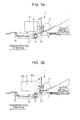
- Figs. 3A and 3B are cross-sectional views of a printer.
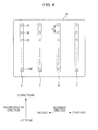
- Fig. 4 is an explanatory view of a configuration of a head.
- Fig. 5 is an explanatory view of a method of a dot formation of two-pass.
- Fig. 6 is an explanatory view of a method of a dot formation of four-pass.
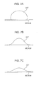
- Figs. 7A to 7C are explanatory views of the relationship between a shape of a UV ink (dots) that impacts on a medium and irradiation energy of a UV of a provisional curing.
- Fig. 8 is an explanatory view of setting of a printing method and a UV irradiation condition of the first embodiment.
- Fig. 9 is a conceptual view of dots formed on unit area respectively in a printing method of a two-pass and a four-pass printing method.
- Fig. 10 is an explanatory view of a head portion of a second embodiment.
- the liquid ejecting apparatus includes a carriage that has a head ejecting liquid cured by receiving the irradiation of light and moves in a movement direction intersecting a transportation direction of a medium; a first irradiation section that is disposed at the carriage, irradiates the light and is arranged at the upstream side or the downstream side from the head in the movement direction; a second irradiation section that irradiates the light and is arranged at the downstream side from the first irradiation section in the transportation direction; and a controller that forms the image on the medium through performing an ejection operation ejecting the liquid from the head while moving the carriage in the movement direction and a transportation operation that transports the medium in the transportation direction, and performs control of the irradiation intensity of the light of the first irradiation section at the time of the ejection operation to regulate the surface condition of the image and to change the irradiation intensity of the light of the second irradiation section according to the
- the light is irradiated from the first irradiation section so that the feeling of the image can be regulated and the amount of the light can be secured to completely cure the dots by receiving the irradiation of the light from the second irradiation section. Accordingly, a desired image can be printed while achieving the optimization of the irradiation condition.
- the controller allow the irradiation intensity of the light of the first irradiation section to be a first intensity and the irradiation intensity of the light of the second irradiation section to be a second intensity when the image is a certain surface condition, and wherein the controller allows the irradiation intensity of the light of the first irradiation section to decrease less than the first intensity and the irradiation intensity of the light of the second irradiation section to increase more than the second intensity when the image has a surface condition of a gloss higher than the certain surface condition.
- a suitable irradiation condition can be set for the surface condition of the image to be formed.
- the controller when the controller performs a first print mode that forms dots at a predetermined region of the medium through performing the ejection operation n times (n is a natural number), or a second print mode that forms dots at the predetermined region through performing the ejection operation m times (m is a natural number larger than n) and then the image of the predetermined surface condition is printed, the irradiation intensity of the light of each of the irradiation sections in the second print mode is decreased less than the irradiation intensity of the light of each of the irradiation sections in the first print mode.
- the irradiation condition suitable for the print mode can be set.
- the controller performs the irradiation operation that allows each of irradiation sections to irradiate the light while moving the carriage in the movement direction without ejecting the liquid from the head between the ejection operation and the transportation operation.
- the image formed on the medium can be further reliably cured.
- the controller changes the irradiation intensity of the light of the first irradiation section and the second irradiation section according to types of media.
- the irradiation condition of the light can be further optimized.
- the second irradiation section is disposed at the carriage.
- the second irradiation section moves with the carriage in the movement direction so that the light can be irradiated to the image (the image after the light is irradiated by the first irradiation section) formed on the medium by the head. Accordingly, miniaturization of the second irradiation section can be achieved compared to the case where the second irradiation section is disposed through a length equal to or greater than the width of the printable medium.
- the method includes regulating the surface condition of the image with controlling the irradiation intensity of the light of a first irradiation section that is disposed at the carriage and arranged at the upstream side or the downstream side from the head in the movement direction at the time of the ejection operation; and changing the irradiation intensity of the light of a second irradiation section disposed at the downstream side from the first irradiation section in the transportation direction according to the irradiation intensity of the light of the first irradiation section.
- an ink jet printer (hereinafter, also referred to as a printer 1) will be described as an example of the liquid ejecting apparatus.
- Fig. 1 is a block diagram illustrating a configuration of the printer 1.
- Fig. 2 is a schematic view of a periphery of a head of the printer 1.
- Figs. 3A and 3B are cross-sectional views of the printer 1.
- Fig. 3A is taken along IIIA-IIIA line in Fig. 2 and
- Fig. 3B is taken along IIIB-IIIB line in Fig. 2 .
- the printer 1 of the embodiment is an apparatus printing an image on the medium by ejecting ultraviolet curable ink (hereinafter, also referred to as a UV ink) to the medium such as paper, cloth, a film sheet or the like.
- the ultraviolet curable ink is cured by receiving the irradiation of ultraviolet rays (hereinafter, also referred to as UV) that is a type of light.
- the UV ink is an ink including an ultraviolet curable resin and is cured due to a light polymerization reaction in the ultraviolet curable resin when receiving the irradiation of UV.
- the printer 1 of the embodiment prints the image using four colors of UV ink of CMYK.
- the printer 1 has a transportation unit 10, a carriage unit 20, a head unit 30, an irradiation unit 40, a detector group 50 and a controller 60.
- the printer 1 receives print data from a computer 110 that is an external apparatus that performs the control of each unit (the transportation unit 10, the carriage unit 20, the head unit 30 and the irradiation unit 40) with the controller 60.
- the controller 60 performs control of each unit and prints the image on the medium based on the print data received from the computer 110.
- the situation inside the printer 1 is monitored by the detector group 50 and the detector group 50 outputs the result of the detection to the controller 60.
- the controller 60 performs the control of each unit based on the result of the detection output from the detector group 50.
- the transportation unit 10 is for transporting the medium (for example, the paper) in a predetermined direction (hereinafter, referred to as the transportation direction).
- the transportation unit 10 has a paper feeding roller 11, a transportation motor (not shown), a transportation roller 13, a platen 14 and a paper discharging roller 15.
- the paper feeding roller 11 is a roller for feeding the medium inserted in a paper inserting port into the printer.
- the transportation roller 13 is a roller transporting the medium that is fed by the paper feeding roller 11 to a printable region and is driven by a transportation motor.
- the platen 14 supports the medium that is in the printing.
- the paper discharging roller 15 is a roller discharging the medium outside the printer and is disposed at the downstream side with respect to the printable region in the transportation direction.
- the carriage unit 20 moves (also referred to as "scanning") the head in a predetermined direction (hereinafter, referred to as a movement direction).
- the carriage unit 20 has a carriage 21 and a carriage motor (not shown).
- the carriage 21 detachably holds the ink cartridge accommodating the UV ink.
- the carriage 21 reciprocates along the guide shaft 24 with the carriage motor in a supported state at the guide shaft 24 intersecting the transportation direction (described below).
- the head unit 30 is for ejecting the liquid (the UV ink in the embodiment) on the medium.
- the head unit 30 includes a head 31 having a plurality of nozzles. Since the head 31 is disposed at the carriage 21, when the carriage 21 moves in the movement direction, the head 31 also moves in the movement direction. Thus, the UV ink is intermittently ejected when the head 31 moves in the movement direction so that a dot line (a raster line) is formed on the medium along the movement direction.
- a route moving from one end to the other end in Fig. 2 is referred to as an outward trip and a route moving from the other end to one end is referred to as a return trip.
- the UV ink is ejected from the head 31 at both periods of the outward trip and the return trip.
- the printer 1 of the embodiment performs bidirectional printing.
- the irradiation unit 40 irradiates the UV to the UV ink on the medium.
- the dot formed on the medium is cured through receiving irradiation of the UV from the irradiation unit 40.
- the irradiation unit 40 of the embodiment includes first irradiation sections 42a and 42b, and second irradiation sections 43a and 43b.
- each of the irradiation sections (the first irradiation sections 42a and 42b, and the second irradiation sections 43a and 43b) is disposed at the carriage 21.
- the first irradiation sections 42a and 42b and the second irradiation sections 43a and 43b also move in the movement direction.
- the first irradiation sections 42a and 42b are disposed at one end and the other end of the head 31 respectively on the carriage 21 in the movement direction so as to interpose the head 31.
- the length of the first irradiation sections 42a and 42b in the transportation direction is substantially the same as the length of the nozzle column of the head 31.
- the first irradiation sections 42a and 42b are disposed at positions lined up with the nozzle columns of the head 31 in the movement direction.
- the first irradiation sections 42a and 42b move together with the head 31 to irradiate the UV in the range where the nozzle column of the head 31 forms the dot.
- the first irradiation sections 42a and 42b of the embodiment use a light emitting diode (LED) as the UV light source.
- the LED controls the size of an input current so that irradiation energy can be easily changed.
- a plurality of LEDs is arranged along the transportation direction in first irradiation sections 42a and 42b.
- the ON-OFF state of each of the LEDs is controlled so that the irradiation range (the range in the transportation direction) of the UV can be set. For example, if only half of the nozzle columns of the head 31 in the downstream side in the transportation direction are used, the half of the nozzles can irradiate the UV with respect to the range forming the dots.
- the second irradiation sections 43a and 43b are disposed at the downstream side of the first irradiation sections 42a and 42b in the transportation direction respectively.
- the length of the second irradiation sections 43a and 43b in the transportation direction is the same as the length (in other words, the length of the nozzle column of the head 31) of the first irradiation sections 42a and 42b in the transportation direction.
- a plurality of LEDs are disposed along the transportation direction as the light source of the UV irradiation. The ON-OFF state of each of the LEDs is controlled so that the range of the UV irradiation can be set.
- the detector group 50 includes a linear type encoder (not shown), a rotary type encoder (not shown), a paper detection sensor 53, the photosensor 54 or the like.
- the linear type encoder detects the position of the carriage 21 in the movement direction.
- the rotary type encoder detects the amount of rotation of the transportation roller 13.
- the paper detection sensor 53 detects a position of a front end of the medium during feeding the paper.
- the photosensor 54 detects whether or not the medium is present by a light emitting section and a light receiving section attached at the carriage 21. Thus, the photosensor 54 detects the position of the end of the medium while moving by the carriage 21 and the width of the medium can be detected.
- the photosensor 54 can also detect the front end (that is the end to the downstream side in the transportation direction and also referred to as the upper end) and the rear end (that is the end to the upstream side in the transportation direction and also referred to as the lower end) of the medium according to the situation.
- the controller 60 is a control unit (a control section) for performing the control of the printer 1.
- the controller 60 has an interface section 61, a CPU 62, a memory 63 and a unit control circuit 64.
- the interface section 61 performs transmitting and receiving of the data between the computer 110 that is the exterior apparatus and the printer 1.
- the CPU 62 is an arithmetic processing unit for performing the control of the entire printer 1.
- the memory 63 is for reserving a region accommodating program of the CPU 62, a work region or the like, and has a storage element such as a RAM, an EEPROM, or the like.
- the CPU 62 performs the control of each unit via unit control circuit 64 according to the program accommodated in the memory 63.
- the controller 60 alternately repeats an ejection operation ejecting the UV ink from the head 31 during moving in the outward trip direction and the return trip direction, and transportation operation transporting the medium in the transportation direction.
- the image configured of a plurality of dots is printed on the medium.
- the ejection operation is referred to as "a pass”.
- n th pass is referred to as pass n.
- the irradiation of the UV to the dots formed on the medium is also performed.
- the controller 60 performs process described below, to each unit of the printer 1 when printing the print data received from the computer 110.
- the controller 60 rotates the paper feeding roller 11 and transports the medium to be printed (here, a paper S) as far as the transportation roller 13.
- the controller 60 drives a transportation motor (not shown) so as to rotate the transportation roller 13.
- the transportation roller 13 rotates by a predetermined amount of rotation, the paper S is transported with a predetermined amount of the transportation.
- the controller 60 rotates the carriage motor (not shown).
- the carriage 21 moves in the movement direction according to the rotation of the carriage motor.
- the carriage 21 moves in the transportation direction so that the head 31, the first irradiation sections 42a and 42b and the second irradiation sections 43a and 43b disposed at the carriage 21 also move in the movement direction at the same time.
- the controller 60 allows the ink droplets to eject intermittently from the head 31.
- the ink droplets impact the paper S so that the dot column is formed where a plurality of dots is arranged in the movement direction.
- the controller 60 allows the UV irradiation to selectively perform from each of the irradiation sections of the irradiation unit 40.
- the controller 60 allows the transportation motor to drive in the interval of the reciprocating of the head 31.
- the transportation motor generates the driving force in the rotation direction according to the amount of the driving instructed from the controller 60.
- the transportation motor rotates the transportation roller 13.
- the transportation roller 13 rotates by a predetermined amount of rotation, the paper S is transported with the predetermined amount of the transportation.
- the amount of the transportation of the paper S is determined according to the amount of rotation of the transportation roller 13.
- the pass (and the UV irradiation) and the transportation operation of the paper S are alternately and repeatedly performed by reciprocation of the head 31, and the dots are formed on each of the pixels of the paper S.
- the paper S where the printing has been finished is discharged by the paper discharging roller 15 rotating synchronized with the transportation roller 13.
- Fig. 4 is an explanatory view of an example of a configuration of the head 31.
- the lower surface of the head 31 forms a black ink nozzle column K, a cyan ink nozzle column C, a magenta ink nozzle column M and a yellow ink nozzle column Y.
- Each of nozzle columns includes a plurality of nozzles (for example, 180 in the embodiment) which are ejecting ports for ejecting the UV ink of each color.
- the nozzles of each of the nozzle columns are disposed with a nozzle pitch D (for example, 360 dpi) along the transportation direction.
- the nozzles of each of nozzle columns are have numbers that descend to the downstream side in the transportation direction attached.
- a piezoelectric element (not shown) is disposed at each of nozzles as a driving element for ejecting the UV ink from each of nozzles.
- the piezoelectric element is driven by the driving signal so that the droplet-shaped UV ink is ejected from each of nozzles.
- the ejected UV ink impacts the medium and forms the dots.
- the printer 1 of the embodiment performs a printing method (hereinafter, also referred to as two passes) that performs the printing of the region of the length of the nozzle pitch in two passes and a printing method (hereinafter, also referred to as four passes) that performs in four passes.
- a printing method hereinafter, also referred to as two passes
- four passes a printing method that performs in four passes.
- the two pass dot formation method will be described.
- Fig. 5 is an explanatory view of an example of the two pass dot formation method.
- one nozzle column for example, the black nozzle column
- four nozzle columns is illustrated.
- the number of nozzle columns is six.
- the controller 60 when performing the print, performs alternately and repeatedly the ejection operation (the pass) ejecting the ink from the head 31 at the time of moving in the movement direction, and the transportation operation transporting the medium in the transportation direction. Circles in the right in the view illustrate the dots.
- the nozzle column moves in the transportation direction (the up-down direction in the view) in every pass, and it illustrates the relative position of the nozzle column with respect to the medium in the same view. Practically, the medium is transported (moved) in the transportation direction.
- the controller 60 allows the ink to eject from each of the nozzles while moving the head 31 in the movement direction. Accordingly, the dot is formed on the medium at positions (an odd-numbered raster line) corresponding to each of the nozzles.
- the ink is ejected from each of the nozzles while moving the head 31 in the movement direction. Accordingly, the dot is formed on the medium at positions (an even-numbered raster line) corresponding to each of the nozzles.
- the dot column (the raster line 2) is formed by the nozzle #1 between the dot column (the raster line 1) formed at the nozzle #1 and the dot column (the raster line 3) formed at the nozzle #2 at the time of the first pass.
- the raster line 12 formed by the nozzle #6 in the second pass is positioned by the nozzle #1 to the downstream side 0.5D in the transportation direction.
- the ink is ejected from each of the nozzles while moving the head 31 in the movement direction. Accordingly, the dot is formed on the medium at positions (an odd-numbered raster line) corresponding to each of the nozzles.
- the raster line (the raster line 13) is formed by the nozzle #1 of the third pass below the raster line (the raster line 12) formed by the nozzle #6 at the second pass.
- the ink is ejected from each of the nozzles while moving the head 31 in the movement direction. Accordingly, the dot is formed on the medium at positions (an even-numbered raster line) corresponding to each of the nozzles.
- the controller 60 allows the medium to be transported 0.5D in the transportation direction after the odd-numbered pass, and allows the medium to be transported 5.5D in the transportation direction after the even-numbered pass.
- the operation is repeated so that the dot columns lined up in the movement direction and the transportation direction is formed on the medium.
- Fig. 6 is an explanatory view of an example of the four pass dot formation method. Even in Fig. 6 , similar to Fig. 5 , one nozzle column (for example, the black nozzle column) in four nozzle columns is illustrated. Also in this case, the number of nozzle columns is six.
- the controller 60 when performing the print, performs alternately and repeatedly the dot formation operation (the pass) ejecting the ink from the head 31 at the time of moving in the movement direction, and the transportation operation transporting the medium in the transportation direction. Circles in the right in the view illustrate the dots.
- the controller 60 allows the ink to eject from each of the nozzles while moving the head 31 in the movement direction. Accordingly, the dot column is formed on the medium at positions corresponding to each of the nozzles (the raster lines 1, 5, 9, 13, 17 and 21).
- the controller 60 allows the ink to eject from each of the nozzles while moving the head 31 in the movement direction.
- the dot is formed on the medium at positions corresponding to each of the nozzles (the raster lines 2, 6, 10, 14, 18 and 22).
- the controller 60 allows the medium to be transported 0.25D in the transportation direction. Accordingly, the relative position of the head with respect to the medium moves 0.25D to the upstream side in the transportation direction.
- the controller 60 allows the ink to eject from each of the nozzles while moving the head 31 in the movement direction.
- the dot is formed on the medium at positions corresponding to each of the nozzles (the raster lines 3, 7, 11, 15, 19 and 23).
- the controller 60 allows the medium to move 0.25D in the transportation direction. Accordingly, the relative position of the head with respect to the medium moves 0.25D to the upstream side in the transportation direction.
- the controller 60 allows the ink to eject from each of the nozzles while moving the head 31 in the movement direction.
- the dot is formed on the medium at positions corresponding to each of the nozzles (the raster lines 4, 8, 12, 16, 20 and 24).
- the nozzle #1 is corresponding to the position of the nozzle #6 to the upstream side in the transportation direction in the fourth pass.
- the controller 60 allows the ink to eject from each of the nozzles while moving the head 31 in the movement direction.
- the dot is formed on the medium at positions corresponding to each of the nozzles (the raster lines 25, 29, 33, 37, 41 and 45).
- the dot columns lined up in the movement direction and the transportation direction are formed on the medium.
- the UV is irradiated on the UV ink impacted on the medium so that the dots are cured.
- the printer 1 of the embodiment includes the first irradiation sections 42a and 42b, and the second irradiation sections 43a and 43b as the irradiation unit 40.
- the printer 1 performs two-step curing.
- the first irradiation sections 42a and 42b thereof perform the UV irradiation to suppress the flow (widening of the dots) of the UV ink impacted on the medium.
- a provisional curing where the dots are cured to a degree of suppressing the widening of the dots.
- the dots after the provisional curing are not completely cured.
- the second irradiation sections 43a and 43b that are disposed to the downstream side from the first irradiation sections 42a and 42b in the transportation direction perform the UV irradiation to completely cure the dots.
- the dots are completely cured is also referred to as main curing.
- the first irradiation sections 42a and 42b are disposed at the carriage 21 respectively.
- the first irradiation section 42a is disposed at one end of the carriage 21 in the movement direction
- the first irradiation section 42b is disposed at the other end of the carriage 21 in the movement direction. Accordingly, the head 31 and the first irradiation sections 42a and 42b also move in the movement direction according to the moving of the carriage 21. In other words, when the nozzle column of each color of the head 31 reciprocates, the first irradiation sections 42a and 42b reciprocate while maintaining the relative position with respect to the nozzle column of each color.
- the controller 60 allows the UV to irradiate from the first irradiation sections 42a and 42b to the medium when reciprocating. More specifically, when the carriage 21 moves in the outward trip (from one end to the other end), the UV is irradiated from the first irradiation section 42a, and when the carriage 21 moves in the return trip (from the other end to one end), the UV is irradiated from the first irradiation section 42b. In other words, the UV is irradiated from the irradiation section of the upstream side in the movement direction with respect to the head 31. Thus, the dots just after formation on the medium by the head 31 can be cured (the provisional curing).
- the provisional curing is performed at the period in which the head 31 moves in the movement direction and performed in the same pass as forming the dots.
- the light sources (the LEDs) of the first irradiation sections 42a and 42b are accommodated inside the first irradiation sections 42a and 42b respectively so that the light sources are isolated from the head 31. Accordingly, the UV irradiating from the light source is prevented from leaking to the lower surface of the head 31 and then the UV ink is prevented from curing (clogging of the nozzle) adjacent to the opening of each of the nozzles formed at the lower surface thereof.
- the second irradiation sections 43a and 43b are also disposed at the carriage 21 respectively.
- the second irradiation section 43a is disposed at one end of the carriage 21 in the movement direction to the downstream side in the transportation direction of the first irradiation section 42a
- the second irradiation section 43b is disposed at the other end of the carriage 21 in the movement direction to the downstream side in the transportation direction of the second irradiation section 42b.
- the second irradiation sections 43a and 43b are disposed to the downstream side from the nozzle column of the head 31 in the transportation direction.
- the controller 60 also allows the UV to irradiate from the second irradiation sections 43a and 43b at the time of pass.
- the dots where the second irradiation sections 43a and 43b irradiate the UV are the dots (the dots cured by the first irradiation sections 42a and 42b) formed already in the previous pass on the medium.
- the curing is performed in two-step (the provisional curing and the main curing).
- the provisional curing thereof is the UV irradiation to suppress the flow (widening) of the dots or the spread between dots formed on the medium.
- the dot after the provisional curing is not completely cured, and the final dot shape is decided by the provisional curing.
- Figs. 7A to 7C are explanatory views between the shape of the UV ink (dots) impacted on the medium and irradiation energy of the UV of the provisional curing.
- the irradiation energy of the UV in the provisional curing lowers in the order of Fig. 7A, Fig. 7B and Fig. 7C .
- timings of the UV irradiation on the dots are the same as each other (just after the formation of the dots) in each view.
- the flow of the dot decreases.
- the unevenness of the medium surface is large, it becomes a low gloss image quality of (a mat tone) where the gloss of the surface is suppressed.
- bleeding hardly occurs between other inks.
- the flow of the dot increases.
- the unevenness of the medium surface is small, it becomes high gloss image quality (a gloss tone) where the gloss of the surface is increased.
- the irradiation condition of the UV just after the dot formation is changed so that the finish state (feeling) of the image can be regulated.
- the printer 1 of the embodiment includes the first irradiation sections 42a and 42b. Accordingly, the irradiation condition of the UV is changed so that the feeling of the image can be regulated.
- the irradiation energy of the UV irradiation (the UV irradiation of the main curing) performing after the provisional curing is fixed, the irradiation energy of the UV at the time of the provisional curing changes so that there is concern that the dots cannot reliably cure or there is concern that the energy is wasted.
- the feeling of the image can be regulated while achieving the optimization of the irradiation condition of the UV.
- Fig. 8 is an explanatory view of setting of the printing method and the UV irradiation condition in the first embodiment.
- the printer 1 of the embodiment performs two print modes (fast mode and high image quality mode) as the printing methods.
- the fast mode performs the dot formation through two passes as described above
- the high image quality mode performs the dot formation through four passes as described above.
- finish state A is the low gloss image quality (the mat tone)
- finish state C is the image quality of high gloss (the gloss tone)
- finish state B is a state of an intermediate state of the finish state A (the mat tone) and the finish state C (the gloss tone).
- the setting values of the irradiation intensity of UV in each of irradiation section are illustrated in the view.
- the setting values are illustrated in five steps from the minimum intensity to the maximum intensity. "1" is the minimum and "5" is the maximum.
- the controller 60 performs control of the irradiation intensity through changing the input current to the LED of the light source of each irradiation section.
- the finish state of the image can be regulated by receiving the UV irradiation just after the dot formation.
- the amount of the UV irradiation of the first irradiation sections 42a and 42b is changed so that the finish states can be regulated.
- the controller 60 changes the irradiation intensity of the first irradiation sections 42a and 42b according to the finish state set by the user through the user interface. Furthermore, the controller 60 changes the irradiation intensity of the second irradiation sections 43a and 43b according to the irradiation intensity of the first irradiation sections 42a and 42b.
- the irradiation intensity of the first irradiation sections 42a and 42b is "5"
- the irradiation intensity of the second irradiation sections 43a and 43b is "2".
- the UV is irradiated with the maximum irradiation intensity in the first irradiation sections 42a and 42b so that the provisional curing is performed on the dots in a state shown in Fig. 7A .
- the UV is irradiated with a relatively low irradiation intensity in the second irradiation sections 43a and 43b so that the main curing is performed on the dots.
- the irradiation intensity of the first irradiation sections 42a and 42b is "2"
- the irradiation intensity of the second irradiation sections 43a and 43b is "5".
- the UV is irradiated with a relatively low irradiation intensity in the first irradiation sections 42a and 42b so that the provisional curing is performed on the dots in a state shown in Fig. 7A .
- the UV is irradiated with the maximum irradiation intensity in the second irradiation sections 43a and 43b so that the main curing is performed on the dots. Accordingly, the energy is not wasted and the dots can be reliably cured regardless of the finish states.
- the controller 60 set the irradiation intensity of the first irradiation sections 42a and 42b, and the irradiation intensity of the second irradiation sections 43a and 43b respectively according to the finish state set by the user.
- the entire irradiation intensity of the UV of each irradiation section is lower than the fast mode.
- the high image quality is a printing method (see Fig. 6 ) through four passes while the above described fast mode is the printing method (see Fig. 5 ) through two passes.
- Fig. 9 is a conceptual view of the dots forming on a unit area respectively in the two-pass printing method and the four-pass printing method.
- the resolutions in the two-pass printing method and the four-pass printing method are different from each other.
- the number of dots formed on the unit area is different from each other.
- one dot per the unit area is formed in two passes while four dots per the unit area are formed in four passes.
- the dot size of the dot formed in four passes is smaller than the size of the dot formed in two passes.
- the irradiation intensity of the UV required to cure the dots in four passes is smaller than that in two passes.
- the entire irradiation intensity of the UV is set lower than that of the fast mode (two passes).
- the controller 60 changes the irradiation intensity of the first irradiation sections 42a and 42b according to the finish state, furthermore, changes the irradiation intensity of the second irradiation sections 43a and 43b according to the irradiation intensity of the first irradiation sections 42a and 42b. By doing this, the energy is not wasted and the dots can be reliably cured regardless of the finish states.
- the printer 1 of the embodiment has the head 31 ejecting the UV ink.
- the printer 1 includes the carriage 21 that moves in the movement direction intersecting the transportation direction, the first irradiation sections 42a and 42b and the second irradiation sections 43a and 43b that are disposed at the carriage 21 and irradiates the UV, and the controller 60 that forms the image on the medium through performing the pass where the ink is ejected from the head 31 while moving the carriage 21 in the movement direction and through performing the transportation direction that transports the medium in the transportation direction.
- the first irradiation section 42a is arranged at one end side from the head 31 at the carriage 21 in the movement direction
- the first irradiation section 42b is arranged at the other end side from the head 31 in the movement direction.
- the second irradiation sections 43a and 43b are arranged to the downstream side from the first irradiation sections 42a and 42b in the transportation direction.
- the controller 60 performs control of the irradiation intensity of the UV of the first irradiation sections 42a and 42b at the time of the pass so as to regulate the finish state of the image and to change the irradiation intensity of the UV of the second irradiation sections 43a and 43b according to the irradiation intensity of the first irradiation sections 42a and 42b.
- the energy is not wasted and the dots can be reliably cured regardless of the finish states (feeling) of the image.
- desired image can be printed while achieving the optimization of the irradiation condition of the UV.
- such a case is also considered in which the main curing is not permitted even though the UV is irradiated with the strongest irradiation intensity according to the print condition (type of ink, types of media, print environment or the like).
- the transportation operation is not performed after the pass, and an empty pass (corresponding to the irradiation operation) that performs only the UV irradiation from each of irradiation sections may be performed while moving the carriage 21 in the movement direction. Accordingly, the cumulative amount of the UV irradiation can be increased and the dots can be further reliably cured.
- other irradiation section for the main curing may be disposed on the transportation route to the downstream side from the carriage 21 in the transportation direction so that the length thereof in the movement direction is longer than the maximum width of the medium to be the printing object.
- the UV is irradiated from any one of the second irradiation sections 43a and 43b, however, the UV may be irradiated from both the second irradiation sections 43a and 43b.
- Fig. 10 is an explanatory view of a head portion of a second embodiment.
- the configuration of the head is different from the first embodiment.
- the carriage 21 includes four heads (the heads 31a, 31b, 31c and 31d).
- the carriage 21 includes the first irradiation sections 42a and 42b, and the second irradiation sections 43a and 43b.
- the head 31a and the head 31c are arranged lined up in the transportation direction at the other end in the movement direction.
- the head 31b and the head 31d are arranged lined up in the transportation direction at one end in the movement direction.
- each of heads is arranged respectively in shifted manner in the transportation direction.
- the first irradiation sections 42a and 42b are disposed respectively outside each of the heads so as to interpose four heads.
- the second irradiation sections 43a and 43b are disposed respectively at the downstream side of the first irradiation sections 42a and 42b in the transportation direction.
- the length of the first irradiation sections 42a and 42b and the second irradiation sections 43a and 43b in the transportation direction is the same as the length of the nozzle column configured of four heads.
- the print operation (the dot formation and the UV irradiation) of the second embodiment is the same as the first embodiment therefore the description thereof will be omitted.
- the main curing is performed by the second irradiation sections 43a and 43b. Accordingly, the optimization of the condition of the UV irradiation is achieved and desired image can be printed.
- the head 31a and the head 31b at the downstream side in the transportation direction, and the head 31c and the head 31d at the upstream side in the transportation direction may perform the dot formation individually.
- the color inks (CMYK) are ejected with the head 31a and the head 31b at the downstream side in the transportation direction to form the image.
- the medium is transported by as much as the length of the nozzle column of each of the heads so that the clear ink is ejected from the head 31c and the head 31d and the clear ink may be coated on the color image.
- the UV for the provisional curing may be irradiated from the half region at the downstream side of the first irradiation sections 42a and 42b in the transportation direction, and just after the clear ink is coated, the UV for the provisional curing may be irradiated from the half region at the upstream side of the first irradiation sections 42a and 42b in the transportation direction.
- the UV for the main curing may be irradiated from the second irradiation sections 43a and 43b.
- the white ink (W) is ejected from the head 31a and the head 31b at the downstream side in the transportation direction a background image is formed on the medium, after that, the medium is transported by as much as of the nozzle column of each of heads.
- the color ink is ejected from the head 31c and the head 31d in the next pass and then the color image may be formed on the background image.
- the UV for the provisional curing may be irradiated from the half region at the downstream side of the first irradiation sections 42a and 42b in the transportation direction, and just after the color image is formed, the UV for the provisional curing may be irradiated from the half region at the upstream side of the first irradiation sections 42a and 42b in the transportation direction.
- the UV for the main curing may be irradiated from the second irradiation sections 43a and 43b.
- the irradiation intensity of the first irradiation sections 42a and 42b may be changed according to the finish state and the irradiation intensity of the second irradiation sections 43a and 43b may be changed according to the irradiation intensity of the first irradiation sections 42a and 42b.
- a printer has been described as an example of the apparatus, the invention is not limited to the embodiments.
- the same technology as the embodiments may be applied to various liquid ejecting apparatus that applies ink jet technology such as a color filter manufacturing apparatus, a dyeing apparatus, a fine processing apparatus, a semiconductor manufacturing apparatus, a surface processing apparatus, a three-dimensional molding machine, a liquid vaporizer, an organic EL manufacturing apparatus (specifically, polymer EL manufacturing apparatus), a display manufacturing apparatus, a film formation apparatus, a DNA chip manufacturing apparatus or the like.
- the ink has been ejected using the piezoelectric element (the piezo element).
- the method of ejecting the liquid is not limited to the embodiments.
- other methods may be used such as a method of generating bubbles inside the nozzle by receiving heat or the like.
- the ink (the UV ink) that is cured by receiving the irradiation of ultraviolet rays (UV) has been ejected from the nozzle.
- the liquid ejecting from the nozzle is not limited to the above described ink, liquid that is cured by receiving the irradiation of other light (for example, visible ray, or the like) except the UV may be ejected from the nozzle.
- the light for example, visible light or the like
- the light for example, visible light or the like
- the invention may be microwave printing where the dots that are formed by the same nozzle are not adjacent to each other.
- the printing is performed on the same types of media in each of the print modes, however, there is a case that the widening method of the ink (dot) may be varied according to the type of medium.
- the irradiation intensity of each of the irradiation sections may be changed according to the types of media. For example, in a case where the printing is performed on the medium in which the ink is easily widened, the irradiation intensity of each of the irradiation sections may be entirely increased. On the contrary, in a case where the printing is performed on the medium in which the ink is difficult to widen, the irradiation intensity of each of the irradiation sections may be entirely decreased. Accordingly, the optimization of the irradiation condition can be further achieved.
- the first irradiation section 42a and the first irradiation section 42b are disposed at both ends of the carriage 21 in the movement direction respectively, however, it may be disposed on one of either.
- the UV irradiation for the provisional curing can be performed just after the dot formation.
- the second irradiation section 43a and the second irradiation section 43b are disposed at the downstream side of the first irradiation section 42a and the first irradiation section 42b in the transportation direction respectively, however, the invention is not limited to the embodiment.
- any one of the second irradiation section 43a and the second irradiation section 43b may be disposed.
- One irradiation section that has the same configuration as the second irradiation sections 43a and 43b may be disposed at the center (at the downstream side from the head 31 in the transportation direction) of the movement direction of the carriage 21. Even in this case, the UV of the main curing can be irradiated at a pass after the dot formation pass.
- the second irradiation section may be disposed at a location other than the carriage 21.
- the second irradiation section may be disposed on the transportation route at the downstream side from the carriage 21 in the transportation direction.
- the UV for the main curing may be irradiated on the dots (the dots after the provisional curing) formed on the medium.
- the second irradiation section when the second irradiation section is disposed at the carriage 21, the second irradiation section can irradiate the UV while moving with the carriage 21 in the movement direction so that the second irradiation section can be miniaturized.
Landscapes
- Health & Medical Sciences (AREA)
- General Health & Medical Sciences (AREA)
- Toxicology (AREA)
- Ink Jet (AREA)
Abstract
Description
- The present invention relates to a liquid ejecting apparatus and a liquid ejecting method.
- A liquid ejecting apparatus is known in which printing is performed using a liquid (for example, ultraviolet ray (UV) ink) cured by receiving irradiation of light (for example, UV ink). Such a liquid ejecting apparatus includes an irradiation section irradiating light and irradiates the light from the irradiation section to dots after the liquid is ejected to the medium and the dots are formed. As described above, the dots are cured and fixed on the medium so that printing can also be performed to the medium on which the liquid is difficult to absorb.
In addition, as the liquid ejecting apparatus described above, a liquid ejecting apparatus is known in which a carriage moving in the movement direction includes a head ejecting the liquid and an irradiation section arranged at the upstream side or the downstream side from the head in the movement direction (for example,JP-A-2006-289722 - Depending on the application, there are cases where the feeling of the image is changed when printing is performed. In the liquid ejecting apparatus as described above, irradiation intensity of the light is changed just after dot formation and the feeling of the image may be changed. However, when the irradiation intensity of the light is changed, for example, there is a concern that the dots may not be completely cured or that energy is wasted.
- An advantage of some aspects of the invention is that it provides a liquid ejecting apparatus and a liquid ejecting method to print a desired image while achieving optimization of the irradiation conditions of light.
- According to an aspect of the invention, a liquid ejecting apparatus includes a carriage that has a head ejecting liquid cured by receiving the irradiation of light and moves in a movement direction intersecting a transportation direction of a medium; a first irradiation section that is disposed at the carriage, irradiates the light and is arranged at the upstream side or the downstream side from the head in the movement direction; a second irradiation section that irradiates the light and is arranged at the downstream side from the first irradiation section in the transportation direction; and a controller that forms the image on the medium through performing an ejection operation ejecting the liquid from the head while moving the carriage in the movement direction and a transportation operation that transports the medium in the transportation direction, and performs control of the irradiation intensity of the light of the first irradiation section at the time of the ejection operation to regulate the surface condition of the image and to change the irradiation intensity of the light of the second irradiation section according to the irradiation intensity of the light of the first irradiation section.
- The invention will be described with reference to the accompanying drawings, wherein like numbers reference like elements.
-
Fig. 1 is a block diagram illustrating a configuration of a printer. -
Fig. 2 is a schematic view of a periphery of a head of a printer. -
Figs. 3A and 3B are cross-sectional views of a printer. -
Fig. 4 is an explanatory view of a configuration of a head. -
Fig. 5 is an explanatory view of a method of a dot formation of two-pass. -
Fig. 6 is an explanatory view of a method of a dot formation of four-pass. -
Figs. 7A to 7C are explanatory views of the relationship between a shape of a UV ink (dots) that impacts on a medium and irradiation energy of a UV of a provisional curing. -
Fig. 8 is an explanatory view of setting of a printing method and a UV irradiation condition of the first embodiment. -
Fig. 9 is a conceptual view of dots formed on unit area respectively in a printing method of a two-pass and a four-pass printing method. -
Fig. 10 is an explanatory view of a head portion of a second embodiment. - It is clear that the liquid ejecting apparatus includes a carriage that has a head ejecting liquid cured by receiving the irradiation of light and moves in a movement direction intersecting a transportation direction of a medium; a first irradiation section that is disposed at the carriage, irradiates the light and is arranged at the upstream side or the downstream side from the head in the movement direction; a second irradiation section that irradiates the light and is arranged at the downstream side from the first irradiation section in the transportation direction; and a controller that forms the image on the medium through performing an ejection operation ejecting the liquid from the head while moving the carriage in the movement direction and a transportation operation that transports the medium in the transportation direction, and performs control of the irradiation intensity of the light of the first irradiation section at the time of the ejection operation to regulate the surface condition of the image and to change the irradiation intensity of the light of the second irradiation section according to the irradiation intensity of the light of the first irradiation section.
- According to the liquid ejecting apparatus, the light is irradiated from the first irradiation section so that the feeling of the image can be regulated and the amount of the light can be secured to completely cure the dots by receiving the irradiation of the light from the second irradiation section. Accordingly, a desired image can be printed while achieving the optimization of the irradiation condition.
- It is preferable that the controller allow the irradiation intensity of the light of the first irradiation section to be a first intensity and the irradiation intensity of the light of the second irradiation section to be a second intensity when the image is a certain surface condition, and wherein the controller allows the irradiation intensity of the light of the first irradiation section to decrease less than the first intensity and the irradiation intensity of the light of the second irradiation section to increase more than the second intensity when the image has a surface condition of a gloss higher than the certain surface condition.
- According to the liquid ejecting apparatus, a suitable irradiation condition can be set for the surface condition of the image to be formed.
- It is preferable that when the controller performs a first print mode that forms dots at a predetermined region of the medium through performing the ejection operation n times (n is a natural number), or a second print mode that forms dots at the predetermined region through performing the ejection operation m times (m is a natural number larger than n) and then the image of the predetermined surface condition is printed, the irradiation intensity of the light of each of the irradiation sections in the second print mode is decreased less than the irradiation intensity of the light of each of the irradiation sections in the first print mode.
- According to the liquid ejecting apparatus, the irradiation condition suitable for the print mode can be set.
- It is preferable that the controller performs the irradiation operation that allows each of irradiation sections to irradiate the light while moving the carriage in the movement direction without ejecting the liquid from the head between the ejection operation and the transportation operation.
- According to the liquid ejecting apparatus, the image formed on the medium can be further reliably cured.
- It is preferable that the controller changes the irradiation intensity of the light of the first irradiation section and the second irradiation section according to types of media.
- According to the liquid ejecting apparatus, the irradiation condition of the light can be further optimized.
- It is preferable that the second irradiation section is disposed at the carriage.
- According to the liquid ejecting apparatus, even though the length of the second irradiation section in the movement direction is shorter than the width of the medium, the second irradiation section moves with the carriage in the movement direction so that the light can be irradiated to the image (the image after the light is irradiated by the first irradiation section) formed on the medium by the head. Accordingly, miniaturization of the second irradiation section can be achieved compared to the case where the second irradiation section is disposed through a length equal to or greater than the width of the printable medium.
- It is clear that in a liquid ejecting method that forms an image on a medium through performing a transportation operation that transports the medium in the transportation direction and an ejection operation ejecting liquid from a head with the irradiation of the light while moving a carriage having the head in a movement direction intersecting the transportation direction, the method includes regulating the surface condition of the image with controlling the irradiation intensity of the light of a first irradiation section that is disposed at the carriage and arranged at the upstream side or the downstream side from the head in the movement direction at the time of the ejection operation; and changing the irradiation intensity of the light of a second irradiation section disposed at the downstream side from the first irradiation section in the transportation direction according to the irradiation intensity of the light of the first irradiation section.
- In the embodiments below, an ink jet printer (hereinafter, also referred to as a printer 1) will be described as an example of the liquid ejecting apparatus.
- Hereinafter, a
printer 1 of the embodiment will be described with reference toFigs. 1 ,2 ,3A and 3B .Fig. 1 is a block diagram illustrating a configuration of theprinter 1.Fig. 2 is a schematic view of a periphery of a head of theprinter 1.Figs. 3A and 3B are cross-sectional views of theprinter 1.Fig. 3A is taken along IIIA-IIIA line inFig. 2 andFig. 3B is taken along IIIB-IIIB line inFig. 2 . - The
printer 1 of the embodiment is an apparatus printing an image on the medium by ejecting ultraviolet curable ink (hereinafter, also referred to as a UV ink) to the medium such as paper, cloth, a film sheet or the like. The ultraviolet curable ink is cured by receiving the irradiation of ultraviolet rays (hereinafter, also referred to as UV) that is a type of light. The UV ink is an ink including an ultraviolet curable resin and is cured due to a light polymerization reaction in the ultraviolet curable resin when receiving the irradiation of UV. In addition, theprinter 1 of the embodiment prints the image using four colors of UV ink of CMYK. - The
printer 1 has atransportation unit 10, acarriage unit 20, ahead unit 30, anirradiation unit 40, adetector group 50 and acontroller 60. Theprinter 1 receives print data from acomputer 110 that is an external apparatus that performs the control of each unit (thetransportation unit 10, thecarriage unit 20, thehead unit 30 and the irradiation unit 40) with thecontroller 60. Thecontroller 60 performs control of each unit and prints the image on the medium based on the print data received from thecomputer 110. The situation inside theprinter 1 is monitored by thedetector group 50 and thedetector group 50 outputs the result of the detection to thecontroller 60.
Thecontroller 60 performs the control of each unit based on the result of the detection output from thedetector group 50. - The
transportation unit 10 is for transporting the medium (for example, the paper) in a predetermined direction (hereinafter, referred to as the transportation direction). Thetransportation unit 10 has apaper feeding roller 11, a transportation motor (not shown), atransportation roller 13, aplaten 14 and apaper discharging roller 15. Thepaper feeding roller 11 is a roller for feeding the medium inserted in a paper inserting port into the printer. Thetransportation roller 13 is a roller transporting the medium that is fed by thepaper feeding roller 11 to a printable region and is driven by a transportation motor. Theplaten 14 supports the medium that is in the printing. Thepaper discharging roller 15 is a roller discharging the medium outside the printer and is disposed at the downstream side with respect to the printable region in the transportation direction. - The
carriage unit 20 moves (also referred to as "scanning") the head in a predetermined direction (hereinafter, referred to as a movement direction). Thecarriage unit 20 has acarriage 21 and a carriage motor (not shown). In addition, thecarriage 21 detachably holds the ink cartridge accommodating the UV ink. Thus, thecarriage 21 reciprocates along theguide shaft 24 with the carriage motor in a supported state at theguide shaft 24 intersecting the transportation direction (described below). - The
head unit 30 is for ejecting the liquid (the UV ink in the embodiment) on the medium. Thehead unit 30 includes ahead 31 having a plurality of nozzles. Since thehead 31 is disposed at thecarriage 21, when thecarriage 21 moves in the movement direction, thehead 31 also moves in the movement direction. Thus, the UV ink is intermittently ejected when thehead 31 moves in the movement direction so that a dot line (a raster line) is formed on the medium along the movement direction. In addition, hereinafter, a route moving from one end to the other end inFig. 2 is referred to as an outward trip and a route moving from the other end to one end is referred to as a return trip. In the embodiment, the UV ink is ejected from thehead 31 at both periods of the outward trip and the return trip. In other words, theprinter 1 of the embodiment performs bidirectional printing. - In addition, the configuration of the
head 31 will be described. - The
irradiation unit 40 irradiates the UV to the UV ink on the medium. The dot formed on the medium is cured through receiving irradiation of the UV from theirradiation unit 40. Theirradiation unit 40 of the embodiment includesfirst irradiation sections second irradiation sections first irradiation sections second irradiation sections carriage 21. Thus, when thecarriage 21 moves in the movement direction, thefirst irradiation sections second irradiation sections - The
first irradiation sections head 31 respectively on thecarriage 21 in the movement direction so as to interpose thehead 31. The length of thefirst irradiation sections head 31. In other words, thefirst irradiation sections head 31 in the movement direction. Thus, thefirst irradiation sections head 31 to irradiate the UV in the range where the nozzle column of thehead 31 forms the dot. Thefirst irradiation sections first irradiation sections head 31 in the downstream side in the transportation direction are used, the half of the nozzles can irradiate the UV with respect to the range forming the dots. - The
second irradiation sections first irradiation sections second irradiation sections first irradiation sections second irradiation sections first irradiation sections - In addition, the UV irradiation through the
first irradiation sections second irradiation sections - The
detector group 50 includes a linear type encoder (not shown), a rotary type encoder (not shown), apaper detection sensor 53, the photosensor 54 or the like. The linear type encoder detects the position of thecarriage 21 in the movement direction. The rotary type encoder detects the amount of rotation of thetransportation roller 13. Thepaper detection sensor 53 detects a position of a front end of the medium during feeding the paper. Thephotosensor 54 detects whether or not the medium is present by a light emitting section and a light receiving section attached at thecarriage 21. Thus, thephotosensor 54 detects the position of the end of the medium while moving by thecarriage 21 and the width of the medium can be detected. In addition, the photosensor 54 can also detect the front end (that is the end to the downstream side in the transportation direction and also referred to as the upper end) and the rear end (that is the end to the upstream side in the transportation direction and also referred to as the lower end) of the medium according to the situation. - The
controller 60 is a control unit (a control section) for performing the control of theprinter 1. Thecontroller 60 has aninterface section 61, aCPU 62, amemory 63 and aunit control circuit 64. Theinterface section 61 performs transmitting and receiving of the data between thecomputer 110 that is the exterior apparatus and theprinter 1. TheCPU 62 is an arithmetic processing unit for performing the control of theentire printer 1. Thememory 63 is for reserving a region accommodating program of theCPU 62, a work region or the like, and has a storage element such as a RAM, an EEPROM, or the like. TheCPU 62 performs the control of each unit viaunit control circuit 64 according to the program accommodated in thememory 63. - When printing is performed, as described below, the
controller 60 alternately repeats an ejection operation ejecting the UV ink from thehead 31 during moving in the outward trip direction and the return trip direction, and transportation operation transporting the medium in the transportation direction. The image configured of a plurality of dots is printed on the medium. In the description below, the ejection operation is referred to as "a pass". In addition, nth pass is referred to as pass n.
In the event of the pass, as described below, the irradiation of the UV to the dots formed on the medium is also performed. - The
controller 60 performs process described below, to each unit of theprinter 1 when printing the print data received from thecomputer 110. - First, the
controller 60 rotates thepaper feeding roller 11 and transports the medium to be printed (here, a paper S) as far as thetransportation roller 13. Next, thecontroller 60 drives a transportation motor (not shown) so as to rotate thetransportation roller 13. When thetransportation roller 13 rotates by a predetermined amount of rotation, the paper S is transported with a predetermined amount of the transportation. - When the paper S is transported to the lower portion of the
head 31, thecontroller 60 rotates the carriage motor (not shown). Thecarriage 21 moves in the movement direction according to the rotation of the carriage motor. In addition, thecarriage 21 moves in the transportation direction so that thehead 31, thefirst irradiation sections second irradiation sections carriage 21 also move in the movement direction at the same time. Thus, during moving in the movement direction, thecontroller 60 allows the ink droplets to eject intermittently from thehead 31. The ink droplets impact the paper S so that the dot column is formed where a plurality of dots is arranged in the movement direction. In addition, when thecarriage 21 movies in the movement direction, thecontroller 60 allows the UV irradiation to selectively perform from each of the irradiation sections of theirradiation unit 40. - In addition, the
controller 60 allows the transportation motor to drive in the interval of the reciprocating of thehead 31. The transportation motor generates the driving force in the rotation direction according to the amount of the driving instructed from thecontroller 60. Using the driving force, the transportation motor rotates thetransportation roller 13. When thetransportation roller 13 rotates by a predetermined amount of rotation, the paper S is transported with the predetermined amount of the transportation. In other words, the amount of the transportation of the paper S is determined according to the amount of rotation of thetransportation roller 13. As described above, the pass (and the UV irradiation) and the transportation operation of the paper S are alternately and repeatedly performed by reciprocation of thehead 31, and the dots are formed on each of the pixels of the paper S. - The paper S where the printing has been finished is discharged by the
paper discharging roller 15 rotating synchronized with thetransportation roller 13. - In this way, the image is printed on the paper S.
-
Fig. 4 is an explanatory view of an example of a configuration of thehead 31. As shown inFig. 4 , the lower surface of thehead 31 forms a black ink nozzle column K, a cyan ink nozzle column C, a magenta ink nozzle column M and a yellow ink nozzle column Y. Each of nozzle columns includes a plurality of nozzles (for example, 180 in the embodiment) which are ejecting ports for ejecting the UV ink of each color. In the embodiment, the nozzles of each of the nozzle columns are disposed with a nozzle pitch D (for example, 360 dpi) along the transportation direction. - The nozzles of each of nozzle columns are have numbers that descend to the downstream side in the transportation direction attached. A piezoelectric element (not shown) is disposed at each of nozzles as a driving element for ejecting the UV ink from each of nozzles. The piezoelectric element is driven by the driving signal so that the droplet-shaped UV ink is ejected from each of nozzles. The ejected UV ink impacts the medium and forms the dots.
- The
printer 1 of the embodiment performs a printing method (hereinafter, also referred to as two passes) that performs the printing of the region of the length of the nozzle pitch in two passes and a printing method (hereinafter, also referred to as four passes) that performs in four passes. Hereinafter, the dot formation methods of two passes and four passes will be described. - The two pass dot formation method will be described.
-
Fig. 5 is an explanatory view of an example of the two pass dot formation method. In the view, for simplicity of description, one nozzle column (for example, the black nozzle column) in four nozzle columns is illustrated. In addition, for simplicity of description, the number of nozzle columns is six. - As described above, when performing the print, the
controller 60 performs alternately and repeatedly the ejection operation (the pass) ejecting the ink from thehead 31 at the time of moving in the movement direction, and the transportation operation transporting the medium in the transportation direction. Circles in the right in the view illustrate the dots. In addition, for convenience of description, the nozzle column moves in the transportation direction (the up-down direction in the view) in every pass, and it illustrates the relative position of the nozzle column with respect to the medium in the same view. Practically, the medium is transported (moved) in the transportation direction. - In a first pass, the
controller 60 allows the ink to eject from each of the nozzles while moving thehead 31 in the movement direction. Accordingly, the dot is formed on the medium at positions (an odd-numbered raster line) corresponding to each of the nozzles. - In the transportation operation after the first pass, the
controller 60 allows the medium to be transported as much as the half (D/2=0.5D) of the nozzle pitch D in the transportation direction. Accordingly, the relative position of the head with respect to the medium moves 0.5D to the upstream side in the transportation direction. - Even in a second pass, the ink is ejected from each of the nozzles while moving the
head 31 in the movement direction. Accordingly, the dot is formed on the medium at positions (an even-numbered raster line) corresponding to each of the nozzles. As seen from the view, in the second pass, for example, the dot column (the raster line 2) is formed by thenozzle # 1 between the dot column (the raster line 1) formed at thenozzle # 1 and the dot column (the raster line 3) formed at thenozzle # 2 at the time of the first pass. - In the transportation operation after the second pass, the medium is moved 5.5D (=6D-0.5D) in the transportation direction. Accordingly, the relative position of the
head 31 with respect to the medium moves 5.5D to the upstream side in the transportation direction. In other words, as shown inFig. 5 , theraster line 12 formed by thenozzle # 6 in the second pass is positioned by thenozzle # 1 to the downstream side 0.5D in the transportation direction. - Thus, even in a third pass, the ink is ejected from each of the nozzles while moving the
head 31 in the movement direction. Accordingly, the dot is formed on the medium at positions (an odd-numbered raster line) corresponding to each of the nozzles. For example, the raster line (the raster line 13) is formed by thenozzle # 1 of the third pass below the raster line (the raster line 12) formed by thenozzle # 6 at the second pass. - In the transportation operation after the third pass, the medium is transported as much as the half (D/2=0.5D) of the nozzle pitch D in the transportation direction. Accordingly, the relative position of the head with respect to the medium moves as much as 0.5D to the upstream side in the transportation direction.
- Even in the pass of a fourth time, the ink is ejected from each of the nozzles while moving the
head 31 in the movement direction. Accordingly, the dot is formed on the medium at positions (an even-numbered raster line) corresponding to each of the nozzles. - Hereinafter, similar to the above description, the
controller 60 allows the medium to be transported 0.5D in the transportation direction after the odd-numbered pass, and allows the medium to be transported 5.5D in the transportation direction after the even-numbered pass. - The operation is repeated so that the dot columns lined up in the movement direction and the transportation direction is formed on the medium.
- Next, the four pass dot formation method will be described.
-
Fig. 6 is an explanatory view of an example of the four pass dot formation method. Even inFig. 6 , similar toFig. 5 , one nozzle column (for example, the black nozzle column) in four nozzle columns is illustrated. Also in this case, the number of nozzle columns is six. - As described above, when performing the print, the
controller 60 performs alternately and repeatedly the dot formation operation (the pass) ejecting the ink from thehead 31 at the time of moving in the movement direction, and the transportation operation transporting the medium in the transportation direction. Circles in the right in the view illustrate the dots. - In a first pass, the
controller 60 allows the ink to eject from each of the nozzles while moving thehead 31 in the movement direction. Accordingly, the dot column is formed on the medium at positions corresponding to each of the nozzles (theraster lines - In the transportation operation after the first pass, the
controller 60 allows the medium to be transported as much as D/4 (=0.25D) in the transportation direction. Accordingly, the relative position of the head with respect to the medium moves 0.25D to the upstream side in the transportation direction. - Even in a second pass, the
controller 60 allows the ink to eject from each of the nozzles while moving thehead 31 in the movement direction. The dot is formed on the medium at positions corresponding to each of the nozzles (theraster lines - In addition, even in the transportation operation after the second pass, the
controller 60 allows the medium to be transported 0.25D in the transportation direction. Accordingly, the relative position of the head with respect to the medium moves 0.25D to the upstream side in the transportation direction. - Even in a third pass, the
controller 60 allows the ink to eject from each of the nozzles while moving thehead 31 in the movement direction. The dot is formed on the medium at positions corresponding to each of the nozzles (theraster lines - In addition, even in the transportation operation after the third pass, the
controller 60 allows the medium to move 0.25D in the transportation direction. Accordingly, the relative position of the head with respect to the medium moves 0.25D to the upstream side in the transportation direction. - Even in a fourth pass, the
controller 60 allows the ink to eject from each of the nozzles while moving thehead 31 in the movement direction. The dot is formed on the medium at positions corresponding to each of the nozzles (theraster lines - Thus, in the transportation operation after the fourth pass, the
controller 60 allows the medium to move 5.25D (=6D-3/4D) in the transportation direction. Accordingly, the relative position of the head with respect to the medium moves 5.25D to the upstream side in the transportation direction. For example, thenozzle # 1 is corresponding to the position of thenozzle # 6 to the upstream side in the transportation direction in the fourth pass. - Even in a fifth pass, the
controller 60 allows the ink to eject from each of the nozzles while moving thehead 31 in the movement direction. The dot is formed on the medium at positions corresponding to each of the nozzles (theraster lines - Below, the pass and the transportation direction are repeated similarly.
- As shown in the view, the dot columns lined up in the movement direction and the transportation direction are formed on the medium.
- In the embodiment, the UV is irradiated on the UV ink impacted on the medium so that the dots are cured. The
printer 1 of the embodiment includes thefirst irradiation sections second irradiation sections irradiation unit 40. Theprinter 1 performs two-step curing. Thefirst irradiation sections second irradiation sections first irradiation sections - As shown in
Fig. 2 , thefirst irradiation sections carriage 21 respectively. Thefirst irradiation section 42a is disposed at one end of thecarriage 21 in the movement direction, and thefirst irradiation section 42b is disposed at the other end of thecarriage 21 in the movement direction. Accordingly, thehead 31 and thefirst irradiation sections carriage 21. In other words, when the nozzle column of each color of thehead 31 reciprocates, thefirst irradiation sections controller 60 allows the UV to irradiate from thefirst irradiation sections carriage 21 moves in the outward trip (from one end to the other end), the UV is irradiated from thefirst irradiation section 42a, and when thecarriage 21 moves in the return trip (from the other end to one end), the UV is irradiated from thefirst irradiation section 42b. In other words, the UV is irradiated from the irradiation section of the upstream side in the movement direction with respect to thehead 31. Thus, the dots just after formation on the medium by thehead 31 can be cured (the provisional curing). As described above, the provisional curing is performed at the period in which thehead 31 moves in the movement direction and performed in the same pass as forming the dots. In addition, the light sources (the LEDs) of thefirst irradiation sections first irradiation sections head 31. Accordingly, the UV irradiating from the light source is prevented from leaking to the lower surface of thehead 31 and then the UV ink is prevented from curing (clogging of the nozzle) adjacent to the opening of each of the nozzles formed at the lower surface thereof. - As shown in
Fig. 2 , thesecond irradiation sections carriage 21 respectively. Thesecond irradiation section 43a is disposed at one end of thecarriage 21 in the movement direction to the downstream side in the transportation direction of thefirst irradiation section 42a, and thesecond irradiation section 43b is disposed at the other end of thecarriage 21 in the movement direction to the downstream side in the transportation direction of thesecond irradiation section 42b. In other words, thesecond irradiation sections head 31 in the transportation direction. Thecontroller 60 also allows the UV to irradiate from thesecond irradiation sections second irradiation sections first irradiation sections - As described above, in the embodiment, the curing is performed in two-step (the provisional curing and the main curing). The provisional curing thereof is the UV irradiation to suppress the flow (widening) of the dots or the spread between dots formed on the medium. Thus, the dot after the provisional curing is not completely cured, and the final dot shape is decided by the provisional curing.
-
Figs. 7A to 7C are explanatory views between the shape of the UV ink (dots) impacted on the medium and irradiation energy of the UV of the provisional curing. The irradiation energy of the UV in the provisional curing lowers in the order ofFig. 7A, Fig. 7B and Fig. 7C . In addition, timings of the UV irradiation on the dots are the same as each other (just after the formation of the dots) in each view. - If the irradiation energy of the UV is high at the time of the provisional curing, for example, as shown in
Fig. 7A , the flow of the dot decreases. In this case, since the unevenness of the medium surface is large, it becomes a low gloss image quality of (a mat tone) where the gloss of the surface is suppressed. In addition, in this case, bleeding hardly occurs between other inks. - Meanwhile, if the irradiation energy of the UV is low at the time of the provisional curing, for example, as shown in
Fig. 7C , the flow of the dot increases. In this case, since the unevenness of the medium surface is small,
it becomes high gloss image quality (a gloss tone) where the gloss of the surface is increased. In addition, in this case, bleeding easily occurs between other inks. - As described above, the irradiation condition of the UV just after the dot formation is changed so that the finish state (feeling) of the image can be regulated. The
printer 1 of the embodiment includes thefirst irradiation sections - In the embodiment, the feeling of the image can be regulated while achieving the optimization of the irradiation condition of the UV.
-
Fig. 8 is an explanatory view of setting of the printing method and the UV irradiation condition in the first embodiment. Theprinter 1 of the embodiment performs two print modes (fast mode and high image quality mode) as the printing methods. The fast mode performs the dot formation through two passes as described above, and the high image quality mode performs the dot formation through four passes as described above. - In addition, in each of print modes, three of A to C are established as the finish state of the image. The finish state A is the low gloss image quality (the mat tone), the finish state C is the image quality of high gloss (the gloss tone). In addition, the finish state B is a state of an intermediate state of the finish state A (the mat tone) and the finish state C (the gloss tone).
- In addition, the setting values of the irradiation intensity of UV in each of irradiation section are illustrated in the view. The setting values are illustrated in five steps from the minimum intensity to the maximum intensity. "1" is the minimum and "5" is the maximum. The
controller 60 performs control of the irradiation intensity through changing the input current to the LED of the light source of each irradiation section. - As described above, the finish state of the image can be regulated by receiving the UV irradiation just after the dot formation. In the case of the embodiment, the amount of the UV irradiation of the
first irradiation sections controller 60 changes the irradiation intensity of thefirst irradiation sections controller 60 changes the irradiation intensity of thesecond irradiation sections first irradiation sections - For example, if the finish state A (the mat tone) is set, the irradiation intensity of the
first irradiation sections second irradiation sections first irradiation sections Fig. 7A . Thus, in the pass after that, the UV is irradiated with a relatively low irradiation intensity in thesecond irradiation sections - In addition, if the finish state C (the gloss tone) is set, the irradiation intensity of the
first irradiation sections second irradiation sections first irradiation sections Fig. 7A . Thus, in the pass after that, the UV is irradiated with the maximum irradiation intensity in thesecond irradiation sections - Even in the high image quality mode, similar to the fast mode, the
controller 60 set the irradiation intensity of thefirst irradiation sections second irradiation sections Fig. 6 ) through four passes while the above described fast mode is the printing method (seeFig. 5 ) through two passes. -
Fig. 9 is a conceptual view of the dots forming on a unit area respectively in the two-pass printing method and the four-pass printing method. As seen from the view, the resolutions in the two-pass printing method and the four-pass printing method are different from each other. In other words, the number of dots formed on the unit area is different from each other. Specifically, one dot per the unit area is formed in two passes while four dots per the unit area are formed in four passes. Thus, the dot size of the dot formed in four passes is smaller than the size of the dot formed in two passes. In other words, the irradiation intensity of the UV required to cure the dots in four passes is smaller than that in two passes. Thus, in the high image quality mode (four passes), the entire irradiation intensity of the UV is set lower than that of the fast mode (two passes). - In addition, even in the high image quality, the
controller 60 changes the irradiation intensity of thefirst irradiation sections second irradiation sections first irradiation sections - As described above, the
printer 1 of the embodiment has thehead 31 ejecting the UV ink. Theprinter 1 includes thecarriage 21 that moves in the movement direction intersecting the transportation direction, thefirst irradiation sections second irradiation sections carriage 21 and irradiates the UV, and thecontroller 60 that forms the image on the medium through performing the pass where the ink is ejected from thehead 31 while moving thecarriage 21 in the movement direction and through performing the transportation direction that transports the medium in the transportation direction. Thefirst irradiation section 42a is arranged at one end side from thehead 31 at thecarriage 21 in the movement direction, and thefirst irradiation section 42b is arranged at the other end side from thehead 31 in the movement direction. In addition, thesecond irradiation sections first irradiation sections - Thus, the
controller 60 performs control of the irradiation intensity of the UV of thefirst irradiation sections second irradiation sections first irradiation sections - Accordingly, the energy is not wasted and the dots can be reliably cured regardless of the finish states (feeling) of the image. In other words, desired image can be printed while achieving the optimization of the irradiation condition of the UV.
- In addition, such a case is also considered in which the main curing is not permitted even though the UV is irradiated with the strongest irradiation intensity according to the print condition (type of ink, types of media, print environment or the like). In this case, the transportation operation is not performed after the pass, and an empty pass (corresponding to the irradiation operation) that performs only the UV irradiation from each of irradiation sections may be performed while moving the
carriage 21 in the movement direction. Accordingly, the cumulative amount of the UV irradiation can be increased and the dots can be further reliably cured. Otherwise, other irradiation section for the main curing may be disposed on the transportation route to the downstream side from thecarriage 21 in the transportation direction so that the length thereof in the movement direction is longer than the maximum width of the medium to be the printing object. - In the embodiment, the UV is irradiated from any one of the
second irradiation sections second irradiation sections -
Fig. 10 is an explanatory view of a head portion of a second embodiment. In the second embodiment, the configuration of the head is different from the first embodiment. - In the second embodiment, the
carriage 21 includes four heads (theheads carriage 21 includes thefirst irradiation sections second irradiation sections - The
head 31a and thehead 31c are arranged lined up in the transportation direction at the other end in the movement direction. In addition, thehead 31b and thehead 31d are arranged lined up in the transportation direction at one end in the movement direction. In addition, each of heads is arranged respectively in shifted manner in the transportation direction. - The
first irradiation sections - In addition, the
second irradiation sections first irradiation sections - The length of the
first irradiation sections second irradiation sections - The print operation (the dot formation and the UV irradiation) of the second embodiment is the same as the first embodiment therefore the description thereof will be omitted.
- Also in the second embodiment, after the provisional curing is performed by the
first irradiation sections second irradiation sections - In addition, in the second embodiment, the
head 31a and thehead 31b at the downstream side in the transportation direction, and thehead 31c and thehead 31d at the upstream side in the transportation direction may perform the dot formation individually. For example, the color inks (CMYK) are ejected with thehead 31a and thehead 31b at the downstream side in the transportation direction to form the image. After that, the medium is transported by as much as the length of the nozzle column of each of the heads so that the clear ink is ejected from thehead 31c and thehead 31d and the clear ink may be coated on the color image. In this case, just after color image is formed, the UV for the provisional curing may be irradiated from the half region at the downstream side of thefirst irradiation sections first irradiation sections second irradiation sections - Otherwise, the white ink (W) is ejected from the
head 31a and thehead 31b at the downstream side in the transportation direction a background image is formed on the medium, after that, the medium is transported by as much as of the nozzle column of each of heads. The color ink is ejected from thehead 31c and thehead 31d in the next pass and then the color image may be formed on the background image. In this case, just after the background image is formed, the UV for the provisional curing may be irradiated from the half region at the downstream side of thefirst irradiation sections first irradiation sections second irradiation sections - Even in these cases, similar to the above described embodiment, the irradiation intensity of the
first irradiation sections second irradiation sections first irradiation sections - The printer or the like has been described as one of embodiments, however, the above described embodiments are for ease of understanding the invention and are not to be construed as limiting the invention. The invention can be modified and improved without departing from the spirit thereof and it is understood that equivalents thereof are also included in the invention. Specifically, embodiments described below are also included in the invention.
- In the above described embodiments, a printer has been described as an example of the apparatus, the invention is not limited to the embodiments. For example, the same technology as the embodiments may be applied to various liquid ejecting apparatus that applies ink jet technology such as a color filter manufacturing apparatus, a dyeing apparatus, a fine processing apparatus, a semiconductor manufacturing apparatus, a surface processing apparatus, a three-dimensional molding machine, a liquid vaporizer, an organic EL manufacturing apparatus (specifically, polymer EL manufacturing apparatus), a display manufacturing apparatus, a film formation apparatus, a DNA chip manufacturing apparatus or the like.
- In the above described embodiments, the ink has been ejected using the piezoelectric element (the piezo element). However, the method of ejecting the liquid is not limited to the embodiments. For example, other methods may be used such as a method of generating bubbles inside the nozzle by receiving heat or the like.
- In the above described embodiments, the ink (the UV ink) that is cured by receiving the irradiation of ultraviolet rays (UV) has been ejected from the nozzle. However, the liquid ejecting from the nozzle is not limited to the above described ink, liquid that is cured by receiving the irradiation of other light (for example, visible ray, or the like) except the UV may be ejected from the nozzle. In this case, the light (for example, visible light or the like) for curing the liquid may be irradiated from each of irradiation sections.
- In the above described embodiments, the description has been made regarding the band print (the printing method that combines a fine transportation filling between the nozzle pitch D and the transportation as many as the nozzle column), however, the invention is not limited to the embodiment, and other printing methods may be used. For example, the invention may be microwave printing where the dots that are formed by the same nozzle are not adjacent to each other.
- In the above described embodiments, the printing is performed on the same types of media in each of the print modes, however, there is a case that the widening method of the ink (dot) may be varied according to the type of medium. In this case, the irradiation intensity of each of the irradiation sections may be changed according to the types of media. For example, in a case where the printing is performed on the medium in which the ink is easily widened, the irradiation intensity of each of the irradiation sections may be entirely increased. On the contrary, in a case where the printing is performed on the medium in which the ink is difficult to widen, the irradiation intensity of each of the irradiation sections may be entirely decreased. Accordingly, the optimization of the irradiation condition can be further achieved.
- In the above described embodiments, the
first irradiation section 42a and thefirst irradiation section 42b are disposed at both ends of thecarriage 21 in the movement direction respectively, however, it may be disposed on one of either. In addition, for example, if the printing is performed in a single direction, when the first irradiation section is disposed at the upstream side of thehead 31 in the movement direction in the pass that forms the dot, the UV irradiation for the provisional curing can be performed just after the dot formation. - In the above described embodiments, the
second irradiation section 43a and thesecond irradiation section 43b are disposed at the downstream side of thefirst irradiation section 42a and thefirst irradiation section 42b in the transportation direction respectively, however, the invention is not limited to the embodiment. For example, any one of thesecond irradiation section 43a and thesecond irradiation section 43b may be disposed. One irradiation section that has the same configuration as thesecond irradiation sections head 31 in the transportation direction) of the movement direction of thecarriage 21. Even in this case, the UV of the main curing can be irradiated at a pass after the dot formation pass.
In addition, the second irradiation section may be disposed at a location other than thecarriage 21. For example, the second irradiation section may be disposed on the transportation route at the downstream side from thecarriage 21 in the transportation direction. Thus, when the medium is transported in the transportation direction, the UV for the main curing may be irradiated on the dots (the dots after the provisional curing) formed on the medium. However, as the embodiment, when the second irradiation section is disposed at thecarriage 21, the second irradiation section can irradiate the UV while moving with thecarriage 21 in the movement direction so that the second irradiation section can be miniaturized.
Claims (7)
- A liquid ejecting apparatus comprising:a carriage that has a head ejecting liquid cured by receiving the irradiation of light and moves in a movement direction intersecting a transportation direction of a medium;a first irradiation section that is disposed at the carriage, irradiates the light and is arranged at an upstream side or a downstream side from the head in the movement direction;a second irradiation section that irradiates the light and is arranged at the downstream side from the first irradiation section in the transportation direction; anda controller that forms the image on the medium through performing an ejection operation ejecting the liquid from the head while moving the carriage in the movement direction and a transportation operation that transports the medium in the transportation direction, and performs control of an irradiation intensity of the light of the first irradiation section at the time of the ejection operation to regulate the surface condition of the image and to change the irradiation intensity of the light of the second irradiation section according to the irradiation intensity of the light of the first irradiation section.
- The liquid ejecting apparatus according to Claim 1,
wherein the controller allows the irradiation intensity of the light of the first irradiation section to be a first intensity and the irradiation intensity of the light of the second irradiation section to be a second intensity when the image is a certain surface condition, and
wherein the controller allows the irradiation intensity of the light of the first irradiation section to decrease less than the first intensity and the irradiation intensity of the light of the second irradiation section to increase more than the second intensity when the image is a surface condition of gloss higher than the certain surface condition. - The liquid ejecting apparatus according to Claim 1 or 2,
wherein when the controller performs a first print mode that forms dots at a predetermined region on the medium through performing the ejection operation n times (n is a natural number), or a second print mode that forms dots at the predetermined region through performing the ejection operation m times (m is a natural number larger than n) and then the image of the predetermined surface condition is printed, the irradiation intensity of the light of each of the irradiation sections in the second print mode is decreased less than the irradiation intensity of the light of each of the irradiation sections in the first print mode. - The liquid ejecting apparatus according to any one of the preceding claims,
wherein the controller performs the irradiation operation that allows each of irradiation sections to irradiate the light while moving the carriage in the movement direction without ejecting the liquid from the head between the ejection operation and the transportation operation. - The liquid ejecting apparatus according to any one of the preceding claims,
wherein the controller changes the irradiation intensity of the light of the first irradiation section and the second irradiation section according to types of media. - The liquid ejecting apparatus according to any one of the preceding claims,
wherein the second irradiation section is disposed at the carriage. - A liquid ejecting method that forms an image on a medium through performing a transportation operation that transports the medium in the transportation direction and an ejection operation ejecting liquid from a head with the irradiation of the light while moving a carriage having the head in a movement direction intersecting the transportation direction, the method comprising:regulating a surface condition of the image with controlling the irradiation intensity of the light of a first irradiation section that is disposed at the carriage and arranged at an upstream side or a downstream side from the head in the movement direction at the time of the ejection operation; andchanging the irradiation intensity of the light of a second irradiation section disposed at the downstream side from the first irradiation section in the transportation direction according to the irradiation intensity of the light of the first irradiation section.
Applications Claiming Priority (1)
| Application Number | Priority Date | Filing Date | Title |
|---|---|---|---|
| JP2011103113A JP5845620B2 (en) | 2011-05-02 | 2011-05-02 | Liquid ejection device |
Publications (3)
| Publication Number | Publication Date |
|---|---|
| EP2520434A2 true EP2520434A2 (en) | 2012-11-07 |
| EP2520434A3 EP2520434A3 (en) | 2017-12-27 |
| EP2520434B1 EP2520434B1 (en) | 2020-03-18 |
Family
ID=46027694
Family Applications (1)
| Application Number | Title | Priority Date | Filing Date |
|---|---|---|---|
| EP12165322.4A Active EP2520434B1 (en) | 2011-05-02 | 2012-04-24 | Liquid ejecting apparatus and liquid ejecting method |
Country Status (4)
| Country | Link |
|---|---|
| US (1) | US8777395B2 (en) |
| EP (1) | EP2520434B1 (en) |
| JP (1) | JP5845620B2 (en) |
| CN (1) | CN102765252B (en) |
Cited By (1)
| Publication number | Priority date | Publication date | Assignee | Title |
|---|---|---|---|---|
| EP3100861A4 (en) * | 2014-01-31 | 2017-05-10 | Mimaki Engineering Co., Ltd. | Inkjet printing apparatus, method for manufacturing printed matter, program, and print medium |
Families Citing this family (11)
| Publication number | Priority date | Publication date | Assignee | Title |
|---|---|---|---|---|
| JP5778125B2 (en) * | 2012-12-27 | 2015-09-16 | 桂川電機株式会社 | UV inkjet printer gloss printing method with transparency and high color density |
| JP6230793B2 (en) * | 2013-01-28 | 2017-11-15 | ローランドディー.ジー.株式会社 | Inkjet recording device |
| JP6102415B2 (en) * | 2013-03-28 | 2017-03-29 | セイコーエプソン株式会社 | Printing apparatus and printing method |
| US8915585B1 (en) * | 2013-07-19 | 2014-12-23 | Mimaki Engineering Co., Ltd. | Printing apparatus and printing method |
| KR20150081101A (en) * | 2014-01-03 | 2015-07-13 | 삼성디스플레이 주식회사 | Apparatus for forming thin film layer and method for forming thin film layer |
| CN106132710B (en) * | 2014-03-12 | 2017-11-17 | 株式会社御牧工程 | Inkjet printing device and inkjet printing method |
| JP6846204B2 (en) * | 2017-01-06 | 2021-03-24 | 株式会社ミマキエンジニアリング | Printing equipment, printing methods and decoration manufacturing methods |
| JP7200704B2 (en) * | 2019-01-31 | 2023-01-10 | セイコーエプソン株式会社 | Three-dimensional modeling apparatus and three-dimensional modeled object modeling method |
| US12588532B2 (en) | 2019-12-26 | 2026-03-24 | Sato Corporation | IC chip mounting device, and IC chip mounting method |
| CN114787977A (en) * | 2019-12-26 | 2022-07-22 | 佐藤控股株式会社 | IC chip mounting device and IC chip mounting method |
| JP2024002022A (en) * | 2022-06-23 | 2024-01-11 | セイコーエプソン株式会社 | Printing device and printing method |
Citations (1)
| Publication number | Priority date | Publication date | Assignee | Title |
|---|---|---|---|---|
| JP2006289722A (en) | 2005-04-08 | 2006-10-26 | Konica Minolta Medical & Graphic Inc | Inkjet recording apparatus and inkjet recording method |
Family Cites Families (19)
| Publication number | Priority date | Publication date | Assignee | Title |
|---|---|---|---|---|
| JP3678301B2 (en) * | 1998-11-24 | 2005-08-03 | セイコーエプソン株式会社 | Inkjet recording method using resin-curable two-component liquid |
| JP2002292907A (en) * | 2001-03-30 | 2002-10-09 | Brother Ind Ltd | Color inkjet recording device |
| EP2565924B1 (en) * | 2001-07-24 | 2018-01-10 | Samsung Electronics Co., Ltd. | Transfer method |
| EP1519839B1 (en) * | 2002-07-01 | 2011-10-05 | Inca Digital Printers Limited | Printing with ink |
| GB0304761D0 (en) * | 2003-03-01 | 2003-04-02 | Integration Technology Ltd | Ultraviolet curing |
| JP4531405B2 (en) * | 2004-01-13 | 2010-08-25 | ローランドディー.ジー.株式会社 | Ink jet printer and printing method |
| US7261408B2 (en) * | 2004-08-20 | 2007-08-28 | Oce Display Graphics Systems | Printing device with radiation source |
| IL164679A0 (en) * | 2004-10-19 | 2005-12-18 | Rafi Bronstein Scitex Vision L | A method of inkjet printing with image quality control |
| JP5095442B2 (en) * | 2008-02-27 | 2012-12-12 | 株式会社ミマキエンジニアリング | Inkjet printer, printing unit and printing method therefor |
| JP5139843B2 (en) * | 2008-02-29 | 2013-02-06 | 株式会社ミマキエンジニアリング | Inkjet printer and printing method |
| JP5324800B2 (en) * | 2008-02-29 | 2013-10-23 | 株式会社ミマキエンジニアリング | Inkjet printer |
| JP5096972B2 (en) * | 2008-03-19 | 2012-12-12 | 株式会社ミマキエンジニアリング | Inkjet printer, printing unit and printing method therefor |
| CN102099194B (en) * | 2008-06-03 | 2014-08-06 | 罗兰Dg有限公司 | Inkjet recording device |
| JP2010149418A (en) * | 2008-12-25 | 2010-07-08 | Seiko Epson Corp | Liquid discharging apparatus, and image forming method |
| JP5560563B2 (en) * | 2009-01-22 | 2014-07-30 | セイコーエプソン株式会社 | Liquid ejection device |
| JP5112360B2 (en) * | 2009-02-27 | 2013-01-09 | 株式会社ミマキエンジニアリング | Inkjet printer and printing method |
| JP2011062995A (en) * | 2009-09-18 | 2011-03-31 | Seiko Epson Corp | Liquid ejecting apparatus |
| JP5504802B2 (en) * | 2009-09-30 | 2014-05-28 | セイコーエプソン株式会社 | Printing apparatus and printing method |
| JP2012106384A (en) * | 2010-11-16 | 2012-06-07 | Fujifilm Corp | Device for forming image and method for forming image |
-
2011
- 2011-05-02 JP JP2011103113A patent/JP5845620B2/en not_active Expired - Fee Related
-
2012
- 2012-04-24 US US13/454,263 patent/US8777395B2/en not_active Expired - Fee Related
- 2012-04-24 EP EP12165322.4A patent/EP2520434B1/en active Active
- 2012-04-28 CN CN201210134953.8A patent/CN102765252B/en not_active Expired - Fee Related
Patent Citations (1)
| Publication number | Priority date | Publication date | Assignee | Title |
|---|---|---|---|---|
| JP2006289722A (en) | 2005-04-08 | 2006-10-26 | Konica Minolta Medical & Graphic Inc | Inkjet recording apparatus and inkjet recording method |
Cited By (1)
| Publication number | Priority date | Publication date | Assignee | Title |
|---|---|---|---|---|
| EP3100861A4 (en) * | 2014-01-31 | 2017-05-10 | Mimaki Engineering Co., Ltd. | Inkjet printing apparatus, method for manufacturing printed matter, program, and print medium |
Also Published As
| Publication number | Publication date |
|---|---|
| US20120281039A1 (en) | 2012-11-08 |
| EP2520434B1 (en) | 2020-03-18 |
| CN102765252B (en) | 2015-07-01 |
| US8777395B2 (en) | 2014-07-15 |
| JP5845620B2 (en) | 2016-01-20 |
| CN102765252A (en) | 2012-11-07 |
| JP2012232515A (en) | 2012-11-29 |
| EP2520434A3 (en) | 2017-12-27 |
Similar Documents
| Publication | Publication Date | Title |
|---|---|---|
| US8777395B2 (en) | Liquid ejecting apparatus and liquid ejecting method | |
| US10112415B2 (en) | Liquid ejecting apparatus and liquid ejecting method | |
| JP5504802B2 (en) | Printing apparatus and printing method | |
| JP5298879B2 (en) | Liquid ejection device and liquid ejection method | |
| JP4026652B2 (en) | Inkjet recording apparatus and inkjet recording method | |
| JP5298897B2 (en) | Liquid ejection device | |
| JP2010149418A (en) | Liquid discharging apparatus, and image forming method | |
| US8864259B2 (en) | Liquid ejecting apparatus and liquid ejecting method | |
| JP5786430B2 (en) | Liquid ejection device | |
| JP2010208217A (en) | Printer and printing method | |
| JP2011073329A (en) | Printer, and printing method | |
| JP5673740B2 (en) | Liquid ejection device | |
| JP2010162766A (en) | Liquid delivering apparatus and liquid delivering method | |
| JP5458724B2 (en) | Printing apparatus and printing method | |
| JP2013028001A (en) | Image forming device and image forming method | |
| JP2006312287A (en) | Printing apparatus, computer program, printing system, and printing method |
Legal Events
| Date | Code | Title | Description |
|---|---|---|---|
| PUAI | Public reference made under article 153(3) epc to a published international application that has entered the european phase |
Free format text: ORIGINAL CODE: 0009012 |
|
| AK | Designated contracting states |
Kind code of ref document: A2 Designated state(s): AL AT BE BG CH CY CZ DE DK EE ES FI FR GB GR HR HU IE IS IT LI LT LU LV MC MK MT NL NO PL PT RO RS SE SI SK SM TR |
|
| AX | Request for extension of the european patent |
Extension state: BA ME |
|
| PUAL | Search report despatched |
Free format text: ORIGINAL CODE: 0009013 |
|
| AK | Designated contracting states |
Kind code of ref document: A3 Designated state(s): AL AT BE BG CH CY CZ DE DK EE ES FI FR GB GR HR HU IE IS IT LI LT LU LV MC MK MT NL NO PL PT RO RS SE SI SK SM TR |
|
| AX | Request for extension of the european patent |
Extension state: BA ME |
|
| RIC1 | Information provided on ipc code assigned before grant |
Ipc: B41J 11/00 20060101AFI20171123BHEP |
|
| STAA | Information on the status of an ep patent application or granted ep patent |
Free format text: STATUS: REQUEST FOR EXAMINATION WAS MADE |
|
| 17P | Request for examination filed |
Effective date: 20180611 |
|
| RBV | Designated contracting states (corrected) |
Designated state(s): AL AT BE BG CH CY CZ DE DK EE ES FI FR GB GR HR HU IE IS IT LI LT LU LV MC MK MT NL NO PL PT RO RS SE SI SK SM TR |
|
| STAA | Information on the status of an ep patent application or granted ep patent |
Free format text: STATUS: EXAMINATION IS IN PROGRESS |
|
| 17Q | First examination report despatched |
Effective date: 20190426 |
|
| GRAP | Despatch of communication of intention to grant a patent |
Free format text: ORIGINAL CODE: EPIDOSNIGR1 |
|
| STAA | Information on the status of an ep patent application or granted ep patent |
Free format text: STATUS: GRANT OF PATENT IS INTENDED |
|
| INTG | Intention to grant announced |
Effective date: 20191113 |
|
| GRAS | Grant fee paid |
Free format text: ORIGINAL CODE: EPIDOSNIGR3 |
|
| GRAA | (expected) grant |
Free format text: ORIGINAL CODE: 0009210 |
|
| STAA | Information on the status of an ep patent application or granted ep patent |
Free format text: STATUS: THE PATENT HAS BEEN GRANTED |
|
| AK | Designated contracting states |
Kind code of ref document: B1 Designated state(s): AL AT BE BG CH CY CZ DE DK EE ES FI FR GB GR HR HU IE IS IT LI LT LU LV MC MK MT NL NO PL PT RO RS SE SI SK SM TR |
|
| REG | Reference to a national code |
Ref country code: GB Ref legal event code: FG4D |
|
| REG | Reference to a national code |
Ref country code: DE Ref legal event code: R096 Ref document number: 602012068516 Country of ref document: DE |
|
| REG | Reference to a national code |
Ref country code: AT Ref legal event code: REF Ref document number: 1245479 Country of ref document: AT Kind code of ref document: T Effective date: 20200415 Ref country code: IE Ref legal event code: FG4D |
|
| PG25 | Lapsed in a contracting state [announced via postgrant information from national office to epo] |
Ref country code: NO Free format text: LAPSE BECAUSE OF FAILURE TO SUBMIT A TRANSLATION OF THE DESCRIPTION OR TO PAY THE FEE WITHIN THE PRESCRIBED TIME-LIMIT Effective date: 20200618 Ref country code: FI Free format text: LAPSE BECAUSE OF FAILURE TO SUBMIT A TRANSLATION OF THE DESCRIPTION OR TO PAY THE FEE WITHIN THE PRESCRIBED TIME-LIMIT Effective date: 20200318 Ref country code: RS Free format text: LAPSE BECAUSE OF FAILURE TO SUBMIT A TRANSLATION OF THE DESCRIPTION OR TO PAY THE FEE WITHIN THE PRESCRIBED TIME-LIMIT Effective date: 20200318 |
|
| PGFP | Annual fee paid to national office [announced via postgrant information from national office to epo] |
Ref country code: FR Payment date: 20200421 Year of fee payment: 9 Ref country code: DE Payment date: 20200416 Year of fee payment: 9 |
|
| REG | Reference to a national code |
Ref country code: NL Ref legal event code: MP Effective date: 20200318 |
|
| PG25 | Lapsed in a contracting state [announced via postgrant information from national office to epo] |
Ref country code: BG Free format text: LAPSE BECAUSE OF FAILURE TO SUBMIT A TRANSLATION OF THE DESCRIPTION OR TO PAY THE FEE WITHIN THE PRESCRIBED TIME-LIMIT Effective date: 20200618 Ref country code: GR Free format text: LAPSE BECAUSE OF FAILURE TO SUBMIT A TRANSLATION OF THE DESCRIPTION OR TO PAY THE FEE WITHIN THE PRESCRIBED TIME-LIMIT Effective date: 20200619 Ref country code: HR Free format text: LAPSE BECAUSE OF FAILURE TO SUBMIT A TRANSLATION OF THE DESCRIPTION OR TO PAY THE FEE WITHIN THE PRESCRIBED TIME-LIMIT Effective date: 20200318 Ref country code: LV Free format text: LAPSE BECAUSE OF FAILURE TO SUBMIT A TRANSLATION OF THE DESCRIPTION OR TO PAY THE FEE WITHIN THE PRESCRIBED TIME-LIMIT Effective date: 20200318 Ref country code: SE Free format text: LAPSE BECAUSE OF FAILURE TO SUBMIT A TRANSLATION OF THE DESCRIPTION OR TO PAY THE FEE WITHIN THE PRESCRIBED TIME-LIMIT Effective date: 20200318 |
|
| PGFP | Annual fee paid to national office [announced via postgrant information from national office to epo] |
Ref country code: GB Payment date: 20200408 Year of fee payment: 9 |
|
| REG | Reference to a national code |
Ref country code: LT Ref legal event code: MG4D |
|
| PG25 | Lapsed in a contracting state [announced via postgrant information from national office to epo] |
Ref country code: NL Free format text: LAPSE BECAUSE OF FAILURE TO SUBMIT A TRANSLATION OF THE DESCRIPTION OR TO PAY THE FEE WITHIN THE PRESCRIBED TIME-LIMIT Effective date: 20200318 |
|
| PG25 | Lapsed in a contracting state [announced via postgrant information from national office to epo] |
Ref country code: CZ Free format text: LAPSE BECAUSE OF FAILURE TO SUBMIT A TRANSLATION OF THE DESCRIPTION OR TO PAY THE FEE WITHIN THE PRESCRIBED TIME-LIMIT Effective date: 20200318 Ref country code: PT Free format text: LAPSE BECAUSE OF FAILURE TO SUBMIT A TRANSLATION OF THE DESCRIPTION OR TO PAY THE FEE WITHIN THE PRESCRIBED TIME-LIMIT Effective date: 20200812 Ref country code: EE Free format text: LAPSE BECAUSE OF FAILURE TO SUBMIT A TRANSLATION OF THE DESCRIPTION OR TO PAY THE FEE WITHIN THE PRESCRIBED TIME-LIMIT Effective date: 20200318 Ref country code: RO Free format text: LAPSE BECAUSE OF FAILURE TO SUBMIT A TRANSLATION OF THE DESCRIPTION OR TO PAY THE FEE WITHIN THE PRESCRIBED TIME-LIMIT Effective date: 20200318 Ref country code: SM Free format text: LAPSE BECAUSE OF FAILURE TO SUBMIT A TRANSLATION OF THE DESCRIPTION OR TO PAY THE FEE WITHIN THE PRESCRIBED TIME-LIMIT Effective date: 20200318 Ref country code: LT Free format text: LAPSE BECAUSE OF FAILURE TO SUBMIT A TRANSLATION OF THE DESCRIPTION OR TO PAY THE FEE WITHIN THE PRESCRIBED TIME-LIMIT Effective date: 20200318 Ref country code: SK Free format text: LAPSE BECAUSE OF FAILURE TO SUBMIT A TRANSLATION OF THE DESCRIPTION OR TO PAY THE FEE WITHIN THE PRESCRIBED TIME-LIMIT Effective date: 20200318 Ref country code: IS Free format text: LAPSE BECAUSE OF FAILURE TO SUBMIT A TRANSLATION OF THE DESCRIPTION OR TO PAY THE FEE WITHIN THE PRESCRIBED TIME-LIMIT Effective date: 20200718 |
|
| REG | Reference to a national code |
Ref country code: AT Ref legal event code: MK05 Ref document number: 1245479 Country of ref document: AT Kind code of ref document: T Effective date: 20200318 |
|
| REG | Reference to a national code |
Ref country code: CH Ref legal event code: PL |
|
| REG | Reference to a national code |
Ref country code: DE Ref legal event code: R097 Ref document number: 602012068516 Country of ref document: DE |
|
| PG25 | Lapsed in a contracting state [announced via postgrant information from national office to epo] |
Ref country code: MC Free format text: LAPSE BECAUSE OF FAILURE TO SUBMIT A TRANSLATION OF THE DESCRIPTION OR TO PAY THE FEE WITHIN THE PRESCRIBED TIME-LIMIT Effective date: 20200318 |
|
| PLBE | No opposition filed within time limit |
Free format text: ORIGINAL CODE: 0009261 |
|
| STAA | Information on the status of an ep patent application or granted ep patent |
Free format text: STATUS: NO OPPOSITION FILED WITHIN TIME LIMIT |
|
| PG25 | Lapsed in a contracting state [announced via postgrant information from national office to epo] |
Ref country code: LU Free format text: LAPSE BECAUSE OF NON-PAYMENT OF DUE FEES Effective date: 20200424 Ref country code: IT Free format text: LAPSE BECAUSE OF FAILURE TO SUBMIT A TRANSLATION OF THE DESCRIPTION OR TO PAY THE FEE WITHIN THE PRESCRIBED TIME-LIMIT Effective date: 20200318 Ref country code: AT Free format text: LAPSE BECAUSE OF FAILURE TO SUBMIT A TRANSLATION OF THE DESCRIPTION OR TO PAY THE FEE WITHIN THE PRESCRIBED TIME-LIMIT Effective date: 20200318 Ref country code: ES Free format text: LAPSE BECAUSE OF FAILURE TO SUBMIT A TRANSLATION OF THE DESCRIPTION OR TO PAY THE FEE WITHIN THE PRESCRIBED TIME-LIMIT Effective date: 20200318 Ref country code: DK Free format text: LAPSE BECAUSE OF FAILURE TO SUBMIT A TRANSLATION OF THE DESCRIPTION OR TO PAY THE FEE WITHIN THE PRESCRIBED TIME-LIMIT Effective date: 20200318 Ref country code: CH Free format text: LAPSE BECAUSE OF NON-PAYMENT OF DUE FEES Effective date: 20200430 Ref country code: LI Free format text: LAPSE BECAUSE OF NON-PAYMENT OF DUE FEES Effective date: 20200430 |
|
| REG | Reference to a national code |
Ref country code: BE Ref legal event code: MM Effective date: 20200430 |
|
| 26N | No opposition filed |
Effective date: 20201221 |
|
| PG25 | Lapsed in a contracting state [announced via postgrant information from national office to epo] |
Ref country code: PL Free format text: LAPSE BECAUSE OF FAILURE TO SUBMIT A TRANSLATION OF THE DESCRIPTION OR TO PAY THE FEE WITHIN THE PRESCRIBED TIME-LIMIT Effective date: 20200318 Ref country code: BE Free format text: LAPSE BECAUSE OF NON-PAYMENT OF DUE FEES Effective date: 20200430 |
|
| PG25 | Lapsed in a contracting state [announced via postgrant information from national office to epo] |
Ref country code: IE Free format text: LAPSE BECAUSE OF NON-PAYMENT OF DUE FEES Effective date: 20200424 |
|
| PG25 | Lapsed in a contracting state [announced via postgrant information from national office to epo] |
Ref country code: SI Free format text: LAPSE BECAUSE OF FAILURE TO SUBMIT A TRANSLATION OF THE DESCRIPTION OR TO PAY THE FEE WITHIN THE PRESCRIBED TIME-LIMIT Effective date: 20200318 |
|
| REG | Reference to a national code |
Ref country code: DE Ref legal event code: R119 Ref document number: 602012068516 Country of ref document: DE |
|
| GBPC | Gb: european patent ceased through non-payment of renewal fee |
Effective date: 20210424 |
|
| PG25 | Lapsed in a contracting state [announced via postgrant information from national office to epo] |
Ref country code: DE Free format text: LAPSE BECAUSE OF NON-PAYMENT OF DUE FEES Effective date: 20211103 Ref country code: FR Free format text: LAPSE BECAUSE OF NON-PAYMENT OF DUE FEES Effective date: 20210430 Ref country code: GB Free format text: LAPSE BECAUSE OF NON-PAYMENT OF DUE FEES Effective date: 20210424 |
|
| PG25 | Lapsed in a contracting state [announced via postgrant information from national office to epo] |
Ref country code: TR Free format text: LAPSE BECAUSE OF FAILURE TO SUBMIT A TRANSLATION OF THE DESCRIPTION OR TO PAY THE FEE WITHIN THE PRESCRIBED TIME-LIMIT Effective date: 20200318 Ref country code: MT Free format text: LAPSE BECAUSE OF FAILURE TO SUBMIT A TRANSLATION OF THE DESCRIPTION OR TO PAY THE FEE WITHIN THE PRESCRIBED TIME-LIMIT Effective date: 20200318 Ref country code: CY Free format text: LAPSE BECAUSE OF FAILURE TO SUBMIT A TRANSLATION OF THE DESCRIPTION OR TO PAY THE FEE WITHIN THE PRESCRIBED TIME-LIMIT Effective date: 20200318 |
|
| PG25 | Lapsed in a contracting state [announced via postgrant information from national office to epo] |
Ref country code: MK Free format text: LAPSE BECAUSE OF FAILURE TO SUBMIT A TRANSLATION OF THE DESCRIPTION OR TO PAY THE FEE WITHIN THE PRESCRIBED TIME-LIMIT Effective date: 20200318 Ref country code: AL Free format text: LAPSE BECAUSE OF FAILURE TO SUBMIT A TRANSLATION OF THE DESCRIPTION OR TO PAY THE FEE WITHIN THE PRESCRIBED TIME-LIMIT Effective date: 20200318 |