EP2520394A1 - Device and method for edge stripping and grooving coated substrates using two laser sources acting on the same side of the coated transparent substrate - Google Patents
Device and method for edge stripping and grooving coated substrates using two laser sources acting on the same side of the coated transparent substrate Download PDFInfo
- Publication number
- EP2520394A1 EP2520394A1 EP20120164228 EP12164228A EP2520394A1 EP 2520394 A1 EP2520394 A1 EP 2520394A1 EP 20120164228 EP20120164228 EP 20120164228 EP 12164228 A EP12164228 A EP 12164228A EP 2520394 A1 EP2520394 A1 EP 2520394A1
- Authority
- EP
- European Patent Office
- Prior art keywords
- laser
- substrate
- exit point
- laser beam
- source
- Prior art date
- Legal status (The legal status is an assumption and is not a legal conclusion. Google has not performed a legal analysis and makes no representation as to the accuracy of the status listed.)
- Granted
Links
Images


Classifications
-
- B—PERFORMING OPERATIONS; TRANSPORTING
- B23—MACHINE TOOLS; METAL-WORKING NOT OTHERWISE PROVIDED FOR
- B23K—SOLDERING OR UNSOLDERING; WELDING; CLADDING OR PLATING BY SOLDERING OR WELDING; CUTTING BY APPLYING HEAT LOCALLY, e.g. FLAME CUTTING; WORKING BY LASER BEAM
- B23K26/00—Working by laser beam, e.g. welding, cutting or boring
- B23K26/02—Positioning or observing the workpiece, e.g. with respect to the point of impact; Aligning, aiming or focusing the laser beam
- B23K26/06—Shaping the laser beam, e.g. by masks or multi-focusing
- B23K26/0604—Shaping the laser beam, e.g. by masks or multi-focusing by a combination of beams
-
- B—PERFORMING OPERATIONS; TRANSPORTING
- B23—MACHINE TOOLS; METAL-WORKING NOT OTHERWISE PROVIDED FOR
- B23K—SOLDERING OR UNSOLDERING; WELDING; CLADDING OR PLATING BY SOLDERING OR WELDING; CUTTING BY APPLYING HEAT LOCALLY, e.g. FLAME CUTTING; WORKING BY LASER BEAM
- B23K26/00—Working by laser beam, e.g. welding, cutting or boring
- B23K26/0006—Working by laser beam, e.g. welding, cutting or boring taking account of the properties of the material involved
-
- B—PERFORMING OPERATIONS; TRANSPORTING
- B23—MACHINE TOOLS; METAL-WORKING NOT OTHERWISE PROVIDED FOR
- B23K—SOLDERING OR UNSOLDERING; WELDING; CLADDING OR PLATING BY SOLDERING OR WELDING; CUTTING BY APPLYING HEAT LOCALLY, e.g. FLAME CUTTING; WORKING BY LASER BEAM
- B23K26/00—Working by laser beam, e.g. welding, cutting or boring
- B23K26/02—Positioning or observing the workpiece, e.g. with respect to the point of impact; Aligning, aiming or focusing the laser beam
- B23K26/06—Shaping the laser beam, e.g. by masks or multi-focusing
- B23K26/062—Shaping the laser beam, e.g. by masks or multi-focusing by direct control of the laser beam
- B23K26/0622—Shaping the laser beam, e.g. by masks or multi-focusing by direct control of the laser beam by shaping pulses
-
- B—PERFORMING OPERATIONS; TRANSPORTING
- B23—MACHINE TOOLS; METAL-WORKING NOT OTHERWISE PROVIDED FOR
- B23K—SOLDERING OR UNSOLDERING; WELDING; CLADDING OR PLATING BY SOLDERING OR WELDING; CUTTING BY APPLYING HEAT LOCALLY, e.g. FLAME CUTTING; WORKING BY LASER BEAM
- B23K26/00—Working by laser beam, e.g. welding, cutting or boring
- B23K26/08—Devices involving relative movement between laser beam and workpiece
- B23K26/083—Devices involving movement of the workpiece in at least one axial direction
-
- B—PERFORMING OPERATIONS; TRANSPORTING
- B23—MACHINE TOOLS; METAL-WORKING NOT OTHERWISE PROVIDED FOR
- B23K—SOLDERING OR UNSOLDERING; WELDING; CLADDING OR PLATING BY SOLDERING OR WELDING; CUTTING BY APPLYING HEAT LOCALLY, e.g. FLAME CUTTING; WORKING BY LASER BEAM
- B23K26/00—Working by laser beam, e.g. welding, cutting or boring
- B23K26/08—Devices involving relative movement between laser beam and workpiece
- B23K26/0869—Devices involving movement of the laser head in at least one axial direction
-
- B—PERFORMING OPERATIONS; TRANSPORTING
- B23—MACHINE TOOLS; METAL-WORKING NOT OTHERWISE PROVIDED FOR
- B23K—SOLDERING OR UNSOLDERING; WELDING; CLADDING OR PLATING BY SOLDERING OR WELDING; CUTTING BY APPLYING HEAT LOCALLY, e.g. FLAME CUTTING; WORKING BY LASER BEAM
- B23K26/00—Working by laser beam, e.g. welding, cutting or boring
- B23K26/352—Working by laser beam, e.g. welding, cutting or boring for surface treatment
- B23K26/354—Working by laser beam, e.g. welding, cutting or boring for surface treatment by melting
-
- B—PERFORMING OPERATIONS; TRANSPORTING
- B23—MACHINE TOOLS; METAL-WORKING NOT OTHERWISE PROVIDED FOR
- B23K—SOLDERING OR UNSOLDERING; WELDING; CLADDING OR PLATING BY SOLDERING OR WELDING; CUTTING BY APPLYING HEAT LOCALLY, e.g. FLAME CUTTING; WORKING BY LASER BEAM
- B23K26/00—Working by laser beam, e.g. welding, cutting or boring
- B23K26/352—Working by laser beam, e.g. welding, cutting or boring for surface treatment
- B23K26/359—Working by laser beam, e.g. welding, cutting or boring for surface treatment by providing a line or line pattern, e.g. a dotted break initiation line
-
- B—PERFORMING OPERATIONS; TRANSPORTING
- B23—MACHINE TOOLS; METAL-WORKING NOT OTHERWISE PROVIDED FOR
- B23K—SOLDERING OR UNSOLDERING; WELDING; CLADDING OR PLATING BY SOLDERING OR WELDING; CUTTING BY APPLYING HEAT LOCALLY, e.g. FLAME CUTTING; WORKING BY LASER BEAM
- B23K26/00—Working by laser beam, e.g. welding, cutting or boring
- B23K26/36—Removing material
- B23K26/362—Laser etching
- B23K26/364—Laser etching for making a groove or trench, e.g. for scribing a break initiation groove
-
- B—PERFORMING OPERATIONS; TRANSPORTING
- B23—MACHINE TOOLS; METAL-WORKING NOT OTHERWISE PROVIDED FOR
- B23K—SOLDERING OR UNSOLDERING; WELDING; CLADDING OR PLATING BY SOLDERING OR WELDING; CUTTING BY APPLYING HEAT LOCALLY, e.g. FLAME CUTTING; WORKING BY LASER BEAM
- B23K26/00—Working by laser beam, e.g. welding, cutting or boring
- B23K26/36—Removing material
- B23K26/40—Removing material taking account of the properties of the material involved
-
- C—CHEMISTRY; METALLURGY
- C03—GLASS; MINERAL OR SLAG WOOL
- C03B—MANUFACTURE, SHAPING, OR SUPPLEMENTARY PROCESSES
- C03B33/00—Severing cooled glass
- C03B33/02—Cutting or splitting sheet glass or ribbons; Apparatus or machines therefor
- C03B33/023—Cutting or splitting sheet glass or ribbons; Apparatus or machines therefor the sheet or ribbon being in a horizontal position
- C03B33/027—Scoring tool holders; Driving mechanisms therefor
-
- C—CHEMISTRY; METALLURGY
- C03—GLASS; MINERAL OR SLAG WOOL
- C03B—MANUFACTURE, SHAPING, OR SUPPLEMENTARY PROCESSES
- C03B33/00—Severing cooled glass
- C03B33/02—Cutting or splitting sheet glass or ribbons; Apparatus or machines therefor
- C03B33/04—Cutting or splitting in curves, especially for making spectacle lenses
-
- C—CHEMISTRY; METALLURGY
- C03—GLASS; MINERAL OR SLAG WOOL
- C03B—MANUFACTURE, SHAPING, OR SUPPLEMENTARY PROCESSES
- C03B33/00—Severing cooled glass
- C03B33/07—Cutting armoured, multi-layered, coated or laminated, glass products
- C03B33/074—Glass products comprising an outer layer or surface coating of non-glass material
-
- C—CHEMISTRY; METALLURGY
- C03—GLASS; MINERAL OR SLAG WOOL
- C03B—MANUFACTURE, SHAPING, OR SUPPLEMENTARY PROCESSES
- C03B33/00—Severing cooled glass
- C03B33/09—Severing cooled glass by thermal shock
- C03B33/091—Severing cooled glass by thermal shock using at least one focussed radiation beam, e.g. laser beam
- C03B33/093—Severing cooled glass by thermal shock using at least one focussed radiation beam, e.g. laser beam using two or more focussed radiation beams
-
- C—CHEMISTRY; METALLURGY
- C03—GLASS; MINERAL OR SLAG WOOL
- C03C—CHEMICAL COMPOSITION OF GLASSES, GLAZES OR VITREOUS ENAMELS; SURFACE TREATMENT OF GLASS; SURFACE TREATMENT OF FIBRES OR FILAMENTS MADE FROM GLASS, MINERALS OR SLAGS; JOINING GLASS TO GLASS OR OTHER MATERIALS
- C03C23/00—Other surface treatment of glass not in the form of fibres or filaments
- C03C23/0005—Other surface treatment of glass not in the form of fibres or filaments by irradiation
- C03C23/0025—Other surface treatment of glass not in the form of fibres or filaments by irradiation by a laser beam
-
- B—PERFORMING OPERATIONS; TRANSPORTING
- B23—MACHINE TOOLS; METAL-WORKING NOT OTHERWISE PROVIDED FOR
- B23K—SOLDERING OR UNSOLDERING; WELDING; CLADDING OR PLATING BY SOLDERING OR WELDING; CUTTING BY APPLYING HEAT LOCALLY, e.g. FLAME CUTTING; WORKING BY LASER BEAM
- B23K2101/00—Articles made by soldering, welding or cutting
- B23K2101/18—Sheet panels
-
- B—PERFORMING OPERATIONS; TRANSPORTING
- B23—MACHINE TOOLS; METAL-WORKING NOT OTHERWISE PROVIDED FOR
- B23K—SOLDERING OR UNSOLDERING; WELDING; CLADDING OR PLATING BY SOLDERING OR WELDING; CUTTING BY APPLYING HEAT LOCALLY, e.g. FLAME CUTTING; WORKING BY LASER BEAM
- B23K2101/00—Articles made by soldering, welding or cutting
- B23K2101/34—Coated articles, e.g. plated or painted; Surface treated articles
-
- B—PERFORMING OPERATIONS; TRANSPORTING
- B23—MACHINE TOOLS; METAL-WORKING NOT OTHERWISE PROVIDED FOR
- B23K—SOLDERING OR UNSOLDERING; WELDING; CLADDING OR PLATING BY SOLDERING OR WELDING; CUTTING BY APPLYING HEAT LOCALLY, e.g. FLAME CUTTING; WORKING BY LASER BEAM
- B23K2103/00—Materials to be soldered, welded or cut
- B23K2103/16—Composite materials, e.g. fibre reinforced
- B23K2103/166—Multilayered materials
- B23K2103/172—Multilayered materials wherein at least one of the layers is non-metallic
-
- B—PERFORMING OPERATIONS; TRANSPORTING
- B23—MACHINE TOOLS; METAL-WORKING NOT OTHERWISE PROVIDED FOR
- B23K—SOLDERING OR UNSOLDERING; WELDING; CLADDING OR PLATING BY SOLDERING OR WELDING; CUTTING BY APPLYING HEAT LOCALLY, e.g. FLAME CUTTING; WORKING BY LASER BEAM
- B23K2103/00—Materials to be soldered, welded or cut
- B23K2103/50—Inorganic material, e.g. metals, not provided for in B23K2103/02 – B23K2103/26
-
- C—CHEMISTRY; METALLURGY
- C03—GLASS; MINERAL OR SLAG WOOL
- C03C—CHEMICAL COMPOSITION OF GLASSES, GLAZES OR VITREOUS ENAMELS; SURFACE TREATMENT OF GLASS; SURFACE TREATMENT OF FIBRES OR FILAMENTS MADE FROM GLASS, MINERALS OR SLAGS; JOINING GLASS TO GLASS OR OTHER MATERIALS
- C03C2218/00—Methods for coating glass
- C03C2218/30—Aspects of methods for coating glass not covered above
- C03C2218/32—After-treatment
- C03C2218/328—Partly or completely removing a coating
Definitions
- the invention relates to a device and a method for edge deletion of coated substrates and for introducing a separating notch for separating the coated substrate into individual modules, e.g. Window panes along a stripped edge strip.
- Coated, transparent substrates in particular of glass, are frequently used with a heat-reflecting coating or a sunscreen coating as architectural glazing or as automotive glass.
- a multi-layer coating is applied to a generally transparent substrate that forms the conductive front and back contacts and the photoactive layer.
- the coating is applied to large glass substrates.
- the individual modules are cut out according to the requested size. If the modules are e.g. to double or multi-pane heat-shield glass, the coating must be removed along the edge of the module. In thin-film solar cells, a stratified edge area additionally ensures complete electrical separation from a frame.
- the DE 10 2008 058 310 B3 describes such a device for processing thin-film solar cells.
- a laser scanner for notching a laser head is used.
- a laser beam is directed onto the coating through a laser scanner through the uncoated side of the substrate.
- a separating notch is introduced through a laser head, which is arranged on the opposite side of the substrate to the laser scanner.
- Laser scanner and laser head are thus located on each of a different side of the substrate.
- such an arrangement complicates the positioning and adjustment of the laser head relative to the laser scanner.
- the position of the separation notch to the stratified edge strip during the stripping can be controlled insufficient.
- the maintenance of a laser system located on different sides of the substrate is complex.
- the device according to the invention for delimiting the edge and for notching a coated transparent substrate comprises a first laser source which emits a first laser beam at a first laser exit point for edge deletion of the coated substrate. It also includes a second laser source that emits a second laser beam at a second laser exit location for introducing a notch into the de-layered edge strip of the substrate.
- the first laser exit point and the second laser exit point are arranged on the same side with respect to a surface of the substrate, so that the first laser beam and the second laser beam act on the coated transparent substrate from the same side.
- the position of the first and second laser beams on a surface of the substrate can be controlled. Since the first and the second laser exit point are arranged on the same side of the substrate, both laser or laser exit points are easily positioned and adjusted to each other. Furthermore, a suction unit is needed only on one side of the substrate, so that the device has a smaller footprint, is inexpensive to purchase and can be operated more easily.
- This can advantageously be achieved if the first and the second Laser beam to the first laser exit point and the second laser exit point facing surface or through the substrate on the side facing away from the two laser exit points of the substrate or on the laser exit points facing away and the laser exit points facing surface of the substrate are focused. There is thus no restriction with respect to the surface of the substrate which is edge-peeled or notched in the case of the predetermined position of the laser exit points.
- the laser beam emitted by the first laser exit point has a constant energy density distribution over the beam cross section, a so-called top-hat profile.
- a constant amount of energy is added over the entire cross section in the layer, so over the entire cross section and in particular at the edge complete erosion of the coating is ensured. It thus does not come to unwanted changes in color or function of the coating at the transition to the stripped edge strip of the substrate. This would be aesthetically disturbing, in particular for architectural glazing.
- the second laser beam is advantageously focused directly onto a surface of the substrate.
- the laser beam emitted by the second laser source preferably has a Gaussian energy density distribution across the beam cross section in the radial direction, so that a high energy density acts on a very small area of the substrate and thus ensures melting of the substrate and a notch deep enough to break arises.
- the introduced energy is optimally utilized by the selected energy density distribution.
- a laser having a first beam shaping unit may form the first laser source, wherein the same laser with a frequency doubling unit and a second beam shaping unit for forming a Gaussian-shaped energy density distribution forms the second laser source.
- the method according to the invention for edge deletion and scoring of a coated transparent substrate comprises the steps of edge stripping the coated substrate with a first laser source emitting a first laser beam at a laser exit location and a notch of the stripped edge strip of the substrate with a second laser source attached to a first laser source second laser exit point emits a second laser beam, wherein the first and the second laser exit point are arranged on the same side with respect to the surface of the substrate, so that the first laser beam and the second laser beam from the same side act on the coated transparent substrate.
- the advantages of the device according to the invention also include the method according to the invention.
- the device can be used for edge deletion and notching of a substrate coated with a silver-based heat-reflecting layer.
- the device according to the invention can also be used for edge deletion and notching of a transparent substrate coated with a sunscreen coating and / or with an electrically conductive coating.
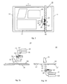
- Fig. 1 shows a section through an edge region of a double-pane insulating glass 1.
- This consists of two Substrates 2, 2 ', which are held by a spacer 7 in the edge region of the substrates 2, 2' at a fixed distance from each other.
- the spacer 7 is bonded by means of a first sealant 5 and a second sealant 6 with the substrates 2, 2 '.
- the substrate 2 ' is provided with a heat-insulating coating 3, by which heat radiation having a wavelength in the mid-infrared range is reflected.
- the heat protection layer 3 consists of a metallic and ceramic layer system whose metallic component often forms a silver layer, which reflects the heat radiation particularly effective and is transparent to visible light.
- the coating 3 at the edge of the substrate in the region 4 must be removed.
- facade glazing without visible frames so-called structural glazing, car glass, which is provided with a sunscreen coating, e.g. based on a tin layer, as well as disks for plasma monitors or even with thin-film solar cells, stripped on the edge to install or cut the cut glass modules can.
- sunscreen coating e.g. based on a tin layer
- disks for plasma monitors or even with thin-film solar cells stripped on the edge to install or cut the cut glass modules
- FIG. 2 a first embodiment of such a Randent Anlagenungs- and notching device 10 is shown.
- a coated substrate 17 rests on a transport system 11, which can move the substrate 17, at least in one direction, for example in the direction of the double arrow Y.
- a bridge 12 spans the transport system 11 and is aligned perpendicular to the transport direction Y of the transport system 11.
- a first laser exit 34 which is in a 2-dimensional Adjustment unit 16 is integrated, mounted on a tool carrier 13.
- a second laser exit point 35 which serves for introducing a notch into the coated substrate 17, is likewise fastened to the bridge 12 via a tool carrier 13 '.
- the tool carriers 13, 13 ' are displaceable in the direction of the double arrow X along the bridge.
- the tool carriers 13, 13 ' can be either individually, as shown, held on the bridge and moved independently of each other or be connected to each other and moved together.
- the first and second laser source can also be performed on a computer, in particular CNC-controlled Adjustarm.
- contours of individual modules 18 are indicated to the left of the bridge.
- the coating is scanned in a strip of a predetermined width by the laser beam, which is scanned from the first laser exit point 34, which is guided by the 2-dimensional adjustment device 16 and removed.
- the laser beam emitted by the second laser exit point 15 generates a notch along which the module is broken out by means of a non-illustrated refracting wheel or cutting blade.
- the edge strip can be stripped and scored along any contour.
- Fig. 3a is the first embodiment Fig. 2 shown in side view.
- the emitted first laser beam 22 is guided through a light guide 23 to the first laser exit point 34 in the 2-dimensional adjustment unit 16.
- the second laser beam 22 'emitted by the second laser source 15 is guided via an optical waveguide 23' to the second laser exit point 35 to the tool carrier 13 ', which is here concealed by the 2-dimensional adjusting unit 16.
- the laser exit points 34, 35, the light guides 23, 23' and the laser sources 14, 15 are easily accessible from one side.
- the first laser beam 22 is focused here on the coating 19, which is applied to the first laser exit point 34 and the second laser exit point 35 facing surface of the substrate 17, and blows them in the reverse direction, ie against the propagation direction of the first laser beam 22 from.
- a suction unit 21 receives the separated particles of the coating 19.
- Fig. 3b shows a second embodiment 20 of the device according to the invention.
- the bridge 12 as well as the first laser exit point 34 and the second laser exit point 35 are arranged on the side of the substrate 17 opposite the coated surface of the substrate 17.
- the first laser beam 22 is focused through the transparent substrate 17 onto the coating 19 and, in the propagation direction of the beam, also called the forward direction, the coating 19 is blown off the surface of the substrate 17.
- the coating particles are received by the suction unit 21 arranged on the coated surface of the substrate 17 side.
- the second laser beam 22 'enters through the substrate 17 and is also focused on the surface opposite the entrance side.
- the first laser 14 and the second laser 15 are directed onto the substrate 17 between eg conveying rollers of a transport system 11 '.
- a transport system 11 for example in the form of a cutting table, as in Fig. 2 and 3a shown, points to a gap, through which the first and second laser beam 22, 22 'can be directed to the substrate 17.
- Particularly suitable solid state lasers such as neodymium (Nd) or ytterbium (Yb) doped YAG lasers, but also Er: YAG lasers, diode lasers or dye lasers, which are light of a wavelength between 1000 nm and 1600 nm, are suitable as the first laser source 14 for removing the coating 19 preferably emit from 1000nm and 1100nm.
- Light in this near-infrared wavelength range between 1000nm and 1600nm is well absorbed by silver, whereas higher-wavelength radiation is reflected in the mid-infrared region and thus used for heat preservation.
- the first laser source 14 is preferably operated in the pulsed mode with a pulse duration between 10ns and 100ns, preferably a pulse duration between 25ns and 35ns.
- the preferred pulse energy density is between 0.1 J / cm 2 to 1 J / cm 2 .
- the second laser source 15 for introducing a notch into the substrate 19 preferably emits laser light having a wavelength between 350 nm and 800 nm, preferably between 500 nm and 550 nm. This wavelength leads to a non-linear bandgap absorption in the substrate 19 and thus to an efficient heating of the substrate 19 in the region of the beam focus.
- the second laser source 15 is also operated in the pulsed mode with a pulse duration between 10ns and 100ns, preferably between 25ns and 35ns, more preferably with 30ns.
- the pulse energy density is between 0.5 kJ / cm 2 and 1.5 kJ / cm 2 .
- a CO 2 laser as a second laser source 15
- the radiation of the CO 2 laser is absorbed directly on the facing surface of the substrate.
- the laser beam 22 emitted from the first laser source 14 focused on the coating 19, and absorbed by the layer with the highest absorption rate for the irradiated laser light.
- the first laser beam 22 is thus absorbed by an infrared (IR) radiation-reflecting metal layer, such as a silver layer 25, which is disposed between a transparent dielectric sub-layer 26 and a transparent dielectric top layer 24.
- IR infrared
- the energy introduced by the first laser beam 22 into the silver layer 25 leads to the evaporation of the silver.
- the pressure wave generated by the high vapor pressure bursts the adjacent lower layer 26 and upper layer 24 with.
- the separated particles are accelerated in the forward direction and received by the suction unit 21.
- the first laser beam 22 has a preferably rectangular or square beam cross section on a constant energy density distribution. This is enlarged with the letter C marked above the first laser beam 22 in FIG Fig. 4 shown. Such an energy density distribution is also called top hat profile. As a result of this energy distribution, the coating 19 is blasted off over the entire width of the beam and thus a surface of the coating 19 which is large in the mm 2 region is removed with a laser shot.
- the second laser beam 22 ' is focused on a surface of the substrate 17 and, in contrast to the first laser beam 22 has an eg circular or elliptical beam cross-section and a Gaussian-shaped energy density distribution D in the radial direction over the Beam cross section on.
- a high energy density is achieved, in particular in the center of the beam, so that the substrate melts there and forms a notch.
- Fig. 4 is shown a removal of the coating in the forward direction.
- the first laser beam 22 enters the substrate 17 through the uncoated surface.
- the focus of the first laser beam 22 is focused on the coating 19.
- the second laser beam 22 ' is here on the surface of the substrate 17, on which the coating 19 was arranged, directed. It is also possible to focus the second laser beam 22 'on the surface opposite the coated surface and there to melt the substrate 17 and to introduce a notch.
- only the breaking tool has to be applied to the surface opposite the notch.
- Fig. 5 shows a sequence of laser spots 29 of the first laser beam 22, which are focused on the coating 19 of the substrate 17.
- the beam cross-section of the first laser beam 22 is rectangular, preferably square with an edge length of about 1mm to 5mm, so that a geradlinier edge of the stripped edge portion 30 is formed.
- successive laser spots overlap by half, so that on average each area of the coating is bombarded with two laser pulses.
- the planar removal of the coating 19 is achieved by moving the first laser beam 22 in the x or y direction through the 2-dimensional adjustment unit.
- a laser spot 27 of the second laser beam 22 ' preferably has a round or elliptical beam cross section with a focus diameter of about 100 ⁇ m and, as a result of the Gaussian energy density distribution, carries a higher amount of energy per area into the substrate. Adjacent laser spots 27 of the second laser beam overlap, creating a uniformly deep, continuous notch. The notch is introduced into the stratified edge region 30.
- the second laser 15 is locally following the first laser 14.
- Fig. 6 shows a first and a second laser source 14, 15, which is fed by a single laser 31.
- the laser beam generated by the laser 31 is guided by a first beam shaping unit 32 and thus forms the first laser source 14.
- the light beam is fed into a light guide 23 and guided to the light entry point 34, not shown.
- the laser beam emitted by the laser 31 is guided via deflecting mirror 37 through a frequency doubling unit 36 and a second beam shaping unit 33 and fed, for example, with a further deflecting mirror into the light guide 23 ', which may be identical to the light guide 23.
Abstract
Description
Die Erfindung betrifft eine Vorrichtung und ein Verfahren zur Randentschichtung beschichteter Substrate und zum Einbringen einer Trennkerbe zur Trennung des beschichteten Substrats in einzelne Module z.B. Fensterscheiben entlang einem entschichteten Randstreifen.The invention relates to a device and a method for edge deletion of coated substrates and for introducing a separating notch for separating the coated substrate into individual modules, e.g. Window panes along a stripped edge strip.
Beschichtete, transparente Substrate, insbesondere aus Glas, werden häufig mit einer wärmereflektierenden Beschichtung bzw. einer Sonnenschutzbeschichtung als Architekturverglasung oder als Automobilglas verwendet. Bei der Herstellung von Dünnschichtsolarzellen wird eine Beschichtung aus mehreren Lagen auf ein zumeist transparentes Substrat aufgebracht, die die leitenden Front- und Rückkontakte sowie die fotoaktive Schicht bilden.Coated, transparent substrates, in particular of glass, are frequently used with a heat-reflecting coating or a sunscreen coating as architectural glazing or as automotive glass. In the manufacture of thin film solar cells, a multi-layer coating is applied to a generally transparent substrate that forms the conductive front and back contacts and the photoactive layer.
Die Beschichtung wird auf großflächige Glassubstrate aufgebracht. In einem separaten Arbeitsgang werden danach die einzelnen Module entsprechend der angeforderten Größe ausgeschnitten. Werden die Module z.B. zu Doppel- oder Multischeiben-Wärmeschutzglas zusammengesetzt, muss die Beschichtung entlang dem Rand des Moduls abgetragen werden. Bei Dünnschichtsolarzellen stellt ein entschichteter Randbereich zusätzlich eine vollständige elektrische Trennung von einem Rahmen sicher.The coating is applied to large glass substrates. In a separate operation, the individual modules are cut out according to the requested size. If the modules are e.g. to double or multi-pane heat-shield glass, the coating must be removed along the edge of the module. In thin-film solar cells, a stratified edge area additionally ensures complete electrical separation from a frame.
Zur Randentschichtung und zum Trennen des Substrats in einzelne Module sind eine Vielzahl von unterschiedlichen Verfahren bekannt, die innerhalb einer Fertigungslinie, aber zeitlich nacheinander und an unterschiedlichen Bearbeitungsstationen ausgeführt werden. Zur Reduzierung von Investitionskosten sind bereits Bearbeitungsstationen bekannt, an denen beide Arbeitsschritte durchgeführt werden können.For edge deletion and for separating the substrate into individual modules, a large number of different methods are known, which are executed within a production line, but in succession and at different processing stations. To reduce investment costs processing stations are already known, where both steps can be performed.
Die
Es ist somit die Aufgabe der vorliegenden Erfindung eine Vorrichtung und ein Verfahren zum Randentschichten und Einbringen einer Trennkerbe in ein beschichtetes transparentes Substrat zu schaffen, die bzw. das eine einfache Justierung des Entschichtungswerkzeugs und des Kerbwerkzeugs ermöglicht, eine einfache und kontinuierliche Überwachung der beiden Vorgänge ermöglicht und einfach zugänglich ist.It is therefore the object of the present invention to provide an apparatus and a method for edge deletion and introduction of a release notch into a coated transparent substrate, which allows for easy adjustment of the stripping tool and the notching tool, enabling easy and continuous monitoring of the two operations and easily accessible.
Die Aufgabe wird durch die erfindungsgemäße Vorrichtung nach Anspruch 1 sowie dem erfindungsgemäßen Verfahren nach Anspruch 15 gelöst. In den Unteransprüchen sind vorteilhafte Weiterbildungen der erfindungsgemäßen Vorrichtung bzw. des erfindungsgemäßen Verfahrens dargestellt.The object is achieved by the device according to the invention as claimed in
Die erfindungsgemäße Vorrichtung zur Randentschichtung und zum Kerben eines beschichteten transparenten Substrats umfasst eine erste Laserquelle, die an einer ersten Laseraustrittsstelle einen ersten Laserstrahl emittiert, zur Randentschichtung des beschichteten Substrats. Sie umfasst ebenfalls eine zweite Laserquelle, die an einer zweiten Laseraustrittsstelle einen zweiten Laserstrahl emittiert, zum Einbringen einer Kerbe in den entschichteten Randstreifen des Substrats. Die erste Laseraustrittsstelle und die zweite Laseraustrittsstelle sind dabei auf der gleichen Seite bezüglich einer Oberfläche des Substrats angeordnet, sodass der erste Laserstrahl und der zweite Laserstrahl von der gleichen Seite auf das beschichtete transparente Substrat einwirken.The device according to the invention for delimiting the edge and for notching a coated transparent substrate comprises a first laser source which emits a first laser beam at a first laser exit point for edge deletion of the coated substrate. It also includes a second laser source that emits a second laser beam at a second laser exit location for introducing a notch into the de-layered edge strip of the substrate. The first laser exit point and the second laser exit point are arranged on the same side with respect to a surface of the substrate, so that the first laser beam and the second laser beam act on the coated transparent substrate from the same side.
Damit kann zu jeder Zeit die Position des ersten und des zweiten Laserstrahls auf einer Oberfläche des Substrats kontrolliert werden. Da die erste und der zweite Laseraustrittsstelle auf der gleichen Seite des Substrats angeordnet sind, sind beide Laser bzw. Laseraustrittsstellen einfach zueinander positionier- und justierbar. Des Weiteren wird lediglich auf einer Seite des Substrats eine Absaugeinheit benötigt, sodass die Vorrichtung einen geringeren Platzbedarf hat, kostengünstig in der Anschaffung ist und einfacher betrieben werden kann.Thus, at any time, the position of the first and second laser beams on a surface of the substrate can be controlled. Since the first and the second laser exit point are arranged on the same side of the substrate, both laser or laser exit points are easily positioned and adjusted to each other. Furthermore, a suction unit is needed only on one side of the substrate, so that the device has a smaller footprint, is inexpensive to purchase and can be operated more easily.
Dabei ist es möglich die Randentschichtung und das Kerben auf der der ersten und zweiten Laseraustrittsstelle zugewandten Oberfläche des Substrats oder auf der der ersten und zweiten Laseraustrittsstelle abgewandten Oberfläche des Substrats durchzuführen bzw. die Randentschichtung auf einer ersten Oberfläche des Substrats durchzuführen und die Kerbe auf einer der ersten Oberfläche gegenüberliegenden zweiten Oberfläche des Substrats einzubringen. Dies kann vorteilhafterweise dadurch erzielt werden, wenn der erste und der zweite Laserstrahl auf die der ersten Laseraustrittsstelle und der zweiten Laseraustrittsstelle zugewandte Oberfläche oder durch das Substrat hindurch auf die den beiden Laseraustrittsstellen abgewandte Oberfläche des Substrats bzw. auf eine den Laseraustrittsstellen abgewandte und eine den Laseraustrittsstellen zugewandte Oberfläche des Substrats fokussiert sind. Es besteht somit bei der vorgegebenen Lage der Laseraustrittsstellen keine Einschränkung bzgl. der Oberfläche des Substrats, die randentschichtet bzw. gekerbt wird.In this case, it is possible to carry out the edge deletion and the notches on the surface of the substrate facing the first and second laser exit points or on the surface of the substrate facing away from the first and second laser exit points or to perform the edge deletion on a first surface of the substrate and the notch on one of the first surface opposite second surface of the substrate to bring. This can advantageously be achieved if the first and the second Laser beam to the first laser exit point and the second laser exit point facing surface or through the substrate on the side facing away from the two laser exit points of the substrate or on the laser exit points facing away and the laser exit points facing surface of the substrate are focused. There is thus no restriction with respect to the surface of the substrate which is edge-peeled or notched in the case of the predetermined position of the laser exit points.
Von Vorteil ist dabei auch, wenn der von der ersten Laseraustrittsstelle emittierte Laserstrahl eine über den Strahlquerschnitt konstante Energiedichteverteilung, ein sogenanntes Top-Hat-Profil, aufweist. Somit wird über den gesamten Querschnitt ein konstanter Energiebetrag in die Schicht eingetragen, sodass über den gesamten Querschnitt und insbesondere auch am Rand eine vollständige Abtragung der Beschichtung gewährleistet ist. Es kommt somit nicht zu ungewollten Farb- oder Funktionsänderungen der Beschichtung am Übergang zum entschichteten Randstreifen des Substrats. Dies wäre insbesondere für Architekturverglasung ästhetisch störend.It is also advantageous if the laser beam emitted by the first laser exit point has a constant energy density distribution over the beam cross section, a so-called top-hat profile. Thus, a constant amount of energy is added over the entire cross section in the layer, so over the entire cross section and in particular at the edge complete erosion of the coating is ensured. It thus does not come to unwanted changes in color or function of the coating at the transition to the stripped edge strip of the substrate. This would be aesthetically disturbing, in particular for architectural glazing.
Zur Einbringung einer Kerbe in das Substrat, die als Trennlinie zum Brechen des Substrats in einzelne Module verwendet wird, ist der zweite Laserstrahl vorteilhafterweise direkt auf eine Oberfläche des Substrats fokussiert. Der von der zweiten Laserquelle emittierte Laserstrahl weist bevorzugt eine Gauß-förmige Energiedichteverteilung über den Strahlquerschnitt in radialer Richtung auf, sodass eine hohe Energiedichte auf einer sehr kleinen Fläche des Substrats wirkt und somit ein Schmelzen des Substrats sicherstellt und eine zum Brechen ausreichend tiefe und schmale Kerbe entsteht. Die eingebrachte Energie wird durch die gewählte Energiedichteverteilung optimal ausgenutzt. Vorteilhafterweise kann ein Laser mit einer ersten Strahlformungseinheit die erste Laserquelle bilden, wobei der gleiche Laser mit einer Frequenz-Verdopplungseinheit und einer zweiten Strahlformungseinheit zur Formung einer Gauß-förmigen Energiedichteverteilung die zweite Laserquelle bildet. Dies stellt eine besonders kostengünstige Vorrichtung dar, da lediglich ein einziger Laser zum Entschichten als auch zum Kerben notwendig ist. Dies ist insbesondere möglich, da für die Einbringung einer Kerbe Laserlicht einer Wellenlänge zwischen 350nm und 800nm, bevorzugt zwischen 500 und 550nm verwendet wird, zur Randentschichtung das Laserlicht bevorzugt bei der etwa doppelten Wellenlänge günstig einsetzbar ist.For introducing a notch into the substrate, which is used as a dividing line for breaking the substrate into individual modules, the second laser beam is advantageously focused directly onto a surface of the substrate. The laser beam emitted by the second laser source preferably has a Gaussian energy density distribution across the beam cross section in the radial direction, so that a high energy density acts on a very small area of the substrate and thus ensures melting of the substrate and a notch deep enough to break arises. The introduced energy is optimally utilized by the selected energy density distribution. Advantageously, a laser having a first beam shaping unit may form the first laser source, wherein the same laser with a frequency doubling unit and a second beam shaping unit for forming a Gaussian-shaped energy density distribution forms the second laser source. This is a particularly inexpensive device, since only a single laser for stripping and for scoring is necessary. This is possible in particular since laser light having a wavelength of between 350 nm and 800 nm, preferably between 500 and 550 nm is used for the introduction of a notch, and the laser light can be advantageously used at about twice the wavelength for edge deletion.
Das erfindungsgemäße Verfahren zur Randentschichtung und zum Kerben eines beschichteten transparenten Substrats umfasst die Verfahrensschritte einer Randentschichtung des beschichteten Substrats mit einer ersten Laserquelle, die an einer Laseraustrittsstelle einen ersten Laserstrahl emittiert, und einem Kerben des entschichteten Randstreifens des Substrats mit einer zweiten Laserquelle, die an einer zweiten Laseraustrittsstelle einen zweiten Laserstrahl emittiert, wobei die erste und die zweite Laseraustrittsstelle auf der gleichen Seite bezüglich der Oberfläche des Substrats angeordnet sind, sodass der erste Laserstrahl und der zweite Laserstrahl von der gleichen Seite auf das beschichtete transparente Substrat einwirken. Die Vorteile der erfindungsgemäßen Vorrichtung weist auch das erfindungsgemäße Verfahren auf.The method according to the invention for edge deletion and scoring of a coated transparent substrate comprises the steps of edge stripping the coated substrate with a first laser source emitting a first laser beam at a laser exit location and a notch of the stripped edge strip of the substrate with a second laser source attached to a first laser source second laser exit point emits a second laser beam, wherein the first and the second laser exit point are arranged on the same side with respect to the surface of the substrate, so that the first laser beam and the second laser beam from the same side act on the coated transparent substrate. The advantages of the device according to the invention also include the method according to the invention.
In besonders vorteilhafter Weise lässt sich die Vorrichtung zum Randentschichten und Kerben eines mit einer silberbasierten wärmereflektierenden Schicht beschichteten Substrats anwenden. Die erfindungsgemäße Vorrichtung ist aber auch zur Randentschichtung und zum Kerben eines mit einer Sonnenschutz-Beschichtung und/oder mit einer elektrisch leitenden Beschichtung beschichteten transparenten Substrats anwendbar.In a particularly advantageous manner, the device can be used for edge deletion and notching of a substrate coated with a silver-based heat-reflecting layer. However, the device according to the invention can also be used for edge deletion and notching of a transparent substrate coated with a sunscreen coating and / or with an electrically conductive coating.
Ausführungsbeispiele der erfindungsgemäßen Vorrichtung bzw. des Verfahrens sind in den Zeichnungen beispielhaft dargestellt und werden anhand der nachfolgenden Beschreibung nachfolgend erläutert. Es zeigen:
- Fig. 1
- einen Randbereich eines Zweischeiben-Isolierglases in Seitenansicht;
- Fig. 2
- ein erstes Ausführungsbeispiel einer erfindungsgemäßen Vorrichtung zur Randentschichtung und zum Kerben in Draufsicht;
- Fig. 3a
- das erste Ausführungsbeispiel einer erfindungsgemäßen Vorrichtung in Seitenansicht;
- Fig. 3b
- ein zweites Ausführungsbeispiel einer erfindungsgemäßen Vorrichtung in Seitenansicht;
- Fig. 4
- ein beschichtetes transparentes Substrat unter Einwirkung eines erfindungsgemäßen ersten und eines zweiten Laserstrahls in schematischer Darstellung;
- Fig. 5
- eine Darstellung von erfindungsgemäßen Laserspots eines ersten und zweiten Laserstrahls auf einem beschichteten transparenten Substrat in Draufsicht und
- Fig. 6
- eine erfindungsgemäße Anordnung einer erste und eine zweite Laserquelle mit einem einzigen Laser in schematischer Darstellung.
- Fig. 1
- an edge region of a two-pane insulating glass in side view;
- Fig. 2
- a first embodiment of a device according to the invention for edge deletion and notches in plan view;
- Fig. 3a
- the first embodiment of a device according to the invention in side view;
- Fig. 3b
- a second embodiment of a device according to the invention in side view;
- Fig. 4
- a coated transparent substrate under the action of a first and a second laser beam according to the invention in a schematic representation;
- Fig. 5
- an illustration of laser spots according to the invention of a first and second laser beam on a coated transparent substrate in plan view and
- Fig. 6
- an inventive arrangement of a first and a second laser source with a single laser in a schematic representation.
Einander entsprechende Teile sind in allen Figuren mit den gleichen Bezugszeichen versehen.Corresponding parts are provided in all figures with the same reference numerals.
Die Wärmeschutzschicht 3 besteht aus einem metallischen sowie keramischen Schichtsystem, dessen metallische Komponente häufig eine Silberschicht bildet, die die Wärmestrahlung besonders effektiv reflektiert und für sichtbares Licht transparent ist. Um eine gute Haftung zwischen dem Substrat und den Dichtmitteln 5, 6 zu erreichen, muss die Beschichtung 3 am Rand des Substrats im Bereich 4 entfernt werden.The
In ähnlicher Weise wird Fassadenverglasung ohne sichtbare Rahmen, sogenanntes Structural Glazing, Autoglas, das mit einer Sonnenschutz-Beschichtung, z.B. basierend auf eine Zinnschicht, versehen ist, sowie Scheiben für Plasmamonitore oder auch bei Dünnschichtsolarzellen, am Rand entschichtet, um die geschnittenen Glasmodule einbauen bzw. einkleben zu können. Die nachfolgend beschriebene Vorrichtung zum Entschichten und Kerben von transparenten Substraten kann für all diese Anwendungen verwendet werden.Similarly, facade glazing without visible frames, so-called structural glazing, car glass, which is provided with a sunscreen coating, e.g. based on a tin layer, as well as disks for plasma monitors or even with thin-film solar cells, stripped on the edge to install or cut the cut glass modules can. The apparatus for stripping and scoring transparent substrates described below can be used for all these applications.
In
Auf dem beschichteten Substrat 17 sind links von der Brücke 12 Konturen von Einzelmodulen 18 angedeutet. Entlang der eingezeichneten Kontur wird die Beschichtung in einem Streifen einer vorbestimmten Breite durch den Laserstrahl, der von der ersten Laseraustrittsstelle 34, die durch die 2-dimensionale Verstellvorrichtung 16 geführt ist, abgescannt und abgetragen. Innerhalb des entschichteten Randstreifens erzeugt der von der zweite Laseraustrittsstelle 15 emittierte Laserstrahl eine Kerbe, entlang derer das Modul mithilfe eines nicht dargestellten Brechrades oder Brechschwerts herausgebrochen wird. Somit kann der Randstreifen entlang einer beliebigen Kontur entschichtet und eingekerbt werden.On the
In
Zur Justierung der Laserstrahlen 22, 22' sind die Laseraustrittsstellen 34, 35, die Lichtleiter 23, 23' sowie die Laserquellen 14, 15 einfach von einer Seite zugänglich. Somit ist die Positionierung der Laserstrahlen 22 und 22', die Einstellung der entsprechenden Abstrahlwinkel sowie die Fokussierung der beiden Laserstrahlen 22, 22' einfach möglich. Der erste Laserstrahl 22 ist hier auf die Beschichtung 19, die auf der der ersten Laseraustrittsstelle 34 und der zweiten Laseraustrittsstelle 35 zugewandten Oberfläche des Substrats 17 aufgebracht ist, fokussiert und sprengt diese in Rückwärtsrichtung, also gegen die Ausbreitungsrichtung des ersten Laserstrahls 22, ab. Eine Absaugeinheit 21 nimmt die abgesprengten Partikel der Beschichtung 19 auf.For adjusting the
Damit das Substrat 17 von unten zugänglich ist, werden der erste Laser 14 und der zweite Laser 15 zwischen z.B. Förderrollen eines Transportsystems 11' auf das Substrat 17 gerichtet. Ein Transportsystem 11 z.B. in Form eines Schneidetisches, wie in
Als erste Laserquelle 14 zur Entfernung der Beschichtung 19 eignen sich insbesondere Festkörperlaser, wie z.B. Neodym (Nd) oder Ytterbium (Yb) dotierte YAG-Laser, aber auch Er:YAG-Laser, Diodenlaser oder Farbstofflaser, die Licht einer Wellenlänge zwischen 1000nm und 1600nm bevorzugt vom 1000nm und 1100nm emittieren. Licht in diese nahen Infrarot-Wellenlängenbereich zwischen 1000nm und 1600nm wird von Silber gut absorbiert, wohingegen Strahlung höherer Wellenlänge im mittleren InfrarotBereich reflektiert und somit zur Wärmeerhaltung genutzt wird. Die erste Laserquelle 14 wird bevorzugt im gepulsten Modus mit einer Pulsdauer zwischen 10ns und 100ns, bevorzugt einer Pulsdauer zwischen 25ns und 35ns betrieben. Die bevorzugte Pulsenergiedichte beträgt zwischen 0,1 J/cm2 bis 1 J/cm2.Particularly suitable solid state lasers, such as neodymium (Nd) or ytterbium (Yb) doped YAG lasers, but also Er: YAG lasers, diode lasers or dye lasers, which are light of a wavelength between 1000 nm and 1600 nm, are suitable as the
Die zweite Laserquelle 15 zum Einbringen einer Kerbe in das Substrat 19 emittiert bevorzugt Laserlicht einer Wellenlänge zwischen 350nm und 800nm, bevorzugt zwischen 500nm und 550nm. Diese Wellenlänge führt zu einer nichtlinearen Bandlücken-Absorption im Substrat 19 und damit zu einer effiziente Aufheizung des Substrats 19 im Bereich des Strahlfokus. Die zweite Laserquelle 15 ist ebenfalls im gepulsten Modus mit einer Pulsdauer zwischen 10ns und 100ns, bevorzugt zwischen 25ns und 35ns, besonders bevorzugt mit 30ns, betrieben. Die Pulsenergiedichte beträgt zwischen 0,5 kJ/cm2 und 1,5 kJ/cm2.The
Wird die Kerbe, wie in
Zur Randentschichtung wird, wie in
Der erste Laserstrahl 22 weist über einen bevorzugt rechteckigen bzw. quadratischen Strahlquerschnitt eine konstante Energiedichteverteilung auf. Diese ist vergrößert mit dem Buchstaben C gekennzeichnet über dem ersten Laserstrahl 22 in
Der zweite Laserstrahl 22' ist auf eine Oberfläche des Substrats 17 fokussiert und weist im Gegensatz zum ersten Laserstrahl 22 einen z.B. kreis- oder ellipsenförmigen Strahlquerschnitt und eine Gauß-förmige Energiedichteverteilung D in radialer Richtung über den Strahlquerschnitt auf. Dadurch wird insbesondere im Zentrum des Strahls eine hohe Energiedichte erreicht, sodass das Substrat dort schmilzt und eine Kerbe bildet.The second laser beam 22 'is focused on a surface of the
In
Ein Laserspot 27 des zweiten Laserstrahls 22' weist bevorzugt einen runden oder elliptischen Strahlquerschnitt mit einem Fokusdurchmesser von etwa 100µm auf und trägt durch die Gauß-förmige Energiedichteverteilung einen höheren Energiebetrag pro Fläche in das Substrat ein. Benachbarte Laserspots 27 des zweiten Laserstrahls überlappen, sodass eine gleichmäßig tiefe, durchgängige Kerbe erzeugt wird. Die Kerbe wird in den entschichteten Randbereich 30 eingebracht. Dazu ist der zweite Laser 15 örtlich dem ersten Laser 14 nachfolgend.A
Die Erfindung ist nicht auf die beschriebenen Ausführungsbeispiele beschränkt. Durch die vorliegende Vorrichtung und das beschriebene Verfahren können nicht nur geradlinige entschichtete Randstreifen sondern beliebige, auch gebogene oder spitzwinklige Konturen, mit einem entschichteten Randstreifen versehen werden. Alle beschriebenen und/oder bezeichneten Merkmale können im Rahmen der Erfindung vorteilhaft miteinander kombiniert werden.The invention is not limited to the described embodiments. By means of the present device and the method described, not only straight-line stripped edge strips but also any curved or acute-angled contours can be provided with a stripped edge strip. All described and / or designated features can be combined advantageously within the scope of the invention.
Claims (24)
einer ersten Laserquelle (14), die an einer ersten Laseraustrittsstelle (34) einen ersten Laserstrahl (22) emittiert, zur Randentschichtung des beschichteten Substrats (17), und
einer zweiten Laserquelle (15), die an einer zweiten Laseraustrittsstelle (35) einen zweiten Laserstrahl (22') emittiert, zum Einbringen einer Kerbe in den entschichteten Randstreifen (30) des Substrats (17), dadurch gekennzeichnet,
dass die erste Laseraustrittsstelle (34) und die zweite Laseraustrittsstelle (35) auf der gleichen Seite bezüglich einer Oberfläche des Substrats (17) angeordnet sind, sodass der erste Laserstrahl (22) und der zweite Laserstrahl (22') von der gleichen Seite auf das beschichtete transparente Substrat einwirken.Device (10, 20) for edge deletion and notching of a coated transparent substrate (17), with
a first laser source (14) which emits a first laser beam (22) at a first laser exit point (34), for edge deletion of the coated substrate (17), and
a second laser source (15) which emits a second laser beam (22 ') at a second laser exit point (35), for introducing a notch into the stripped edge strip (30) of the substrate (17), characterized
that the first laser exit point (34) and the second laser exit point (35) on the same side with respect to a surface of the substrate (17) are arranged so that the first laser beam (22) and the second laser beam (22 ') from the same side of the coated transparent substrate act.
dadurch gekennzeichnet,
dass der erste und der zweite Laserstrahl (22, 22') auf die der ersten Laseraustrittsstelle (34) und der zweiten Laseraustrittsstelle (35) zugewandte Oberfläche des Substrats (17) fokussiert sind oder durch das Substrat (17) hindurch auf die den beiden Laseraustrittsstellen (34, 35) abgewandte Oberfläche des Substrats (17) fokussiert sind oder auf eine den Laseraustrittsstellen (34, 35) abgewandte Oberfläche und eine den Laseraustrittsstellen (34, 35) zugewandte Oberfläche des Substrats (17) fokussiert sind.Device according to claim 1,
characterized,
in that the first and the second laser beam (22, 22 ') are focused on the surface of the substrate (17) facing the first laser exit point (34) and the second laser exit point (35), or on the two laser exit points through the substrate (17) (34, 35) facing away from the surface of the substrate (17) are focused or on a laser exit points (34, 35) facing away from the surface and the laser exit points (34, 35) facing surface of the substrate (17) are focused.
dadurch gekennzeichnet,
dass der erste Laserstrahl (22) eine über den Strahlquerschnitt im wesentlichen konstante Energiedichteverteilung, insbesondere ein Top-Hat-Profil, aufweist.Apparatus according to claim 1 or 2,
characterized,
that the first laser beam (22) has a substantially constant over the beam cross-sectional energy density distribution, in particular a top-hat profile.
dadurch gekennzeichnet,
dass die Strahlquerschnitte von zwei aufeinander folgenden ersten Laserstrahlen (22) zur Hälfte überlappen.Device according to claim 3,
characterized,
that the beam cross sections of two successive first laser beams (22) overlap in half.
dadurch gekennzeichnet,
dass die erste Laserquelle(14) Laserlicht einer Wellenlänge zwischen 1000nm und 1600nm, bevorzugt zwischen 1000nm und 1100nm, besonders bevorzugt bei 1020nm und 1070nm, emittiert und/oder die erste Laserquelle (14) im gepulsten Modus mit einer Pulsdauer zwischen 1ns und 100ns, bevorzugt zwischen 25ns und 35ns, betrieben wird und/oder die erste Laserquelle (14) eine Pulsenergiedichte von 0,1 J/cm2 bis 1 J/cm2 aufweist.Device according to one of claims 1 to 4,
characterized,
that said first laser source (14) laser light having a wavelength between 1000nm and 1600nm, preferably preferably between 1000nm and 1100nm, most preferably 1020nm and 1070nm, emitted and / or the first laser source (14) in pulsed mode with a pulse duration between 1 ns and 100 ns, between 25ns and 35ns, and / or the first laser source (14) has a pulse energy density of 0.1 J / cm 2 to 1 J / cm 2 .
dadurch gekennzeichnet,
dass die erste Laseraustrittsstelle (34) in einer 2-dimensionale Verstelleinheit (16) gehalten ist und über das zu entschichtende Substrat (17) geführt ist.Device according to one of claims 1 to 5,
characterized,
that the first laser exit point (34) is held in a 2-dimensional adjustment unit (16) and over the substrate to be stripped (17) is guided.
dadurch gekennzeichnet,
dass die zweite Laserquelle (15) direkt auf eine Oberfläche des Substrats (17) fokussiert ist.Device according to one of claims 1 to 6,
characterized,
in that the second laser source (15) is focused directly on a surface of the substrate (17).
dadurch gekennzeichnet,
dass der zweite Laserstrahl (22') eine Gauß-förmige Energiedichteverteilung über den Strahlquerschnitt in radialer Richtung aufweist.Device according to one of claims 1 to 7,
characterized,
that the second laser beam (22 ') has a Gaussian power density distribution across the beam cross section in the radial direction.
dadurch gekennzeichnet,
dass die zweite Laserquelle (15) Laserlicht einer Wellenlänge zwischen 350nm und 800nm, bevorzugt von 500nm bis 550nm, emittiert und/oder die zweite Laserquelle (15) im gepulsten Modus mit einer Pulsdauer zwischen 1ns und 100ns, bevorzugt zwischen 25ns und 35ns, betrieben wird und/oder die zweite Laserquelle (15) eine Pulsenergiedichte zwischen 0,5 kJ/cm2 und 1,5 kJ/cm2 aufweist.Device according to one of claims 1 to 8,
characterized,
that said second laser source (15) laser light of a wavelength between 350nm and 800nm, preferably from 500nm to 550nm which emits and / or the second laser source (15) in pulsed mode with a pulse duration between 1 ns and 100 ns, preferably between 25ns and 35ns operated, and / or the second laser source (15) has a pulse energy density between 0.5 kJ / cm 2 and 1.5 kJ / cm 2 .
dadurch gekennzeichnet,
dass ein Laser (31) mit einer ersten Strahlformungseinheit (32) die erste Laserquelle (14) bildet und der gleiche Laser (31) mit einer Frequenzverdoppelungseinheit (36) und einer zweiten Strahlformungs-Einheit (33) die zweite Laserquelle (15) bildet.Device according to one of claims 1 to 9,
characterized,
that a laser (31) having a first beam shaping unit (32) forms the first laser source (14) and the same laser (31) having a frequency doubling unit (36) and a second beam shaping unit (33) forms the second laser source (15).
dadurch gekennzeichnet,
dass der erste Laserstrahl (22) und der zweite Laserstrahl (22') auf die der ersten Laseraustrittsstelle (14) und der zweiten Laseraustrittsstelle (15) zugewandte Oberfläche oder auf die der ersten Laseraustrittsstelle (14) und der zweiten Laseraustrittsstelle (15) abgewandte Oberfläche des Substrats (17) fokussiert sind oder dass der erste Laserstrahl (22) und der zweite Laserstrahl (22') auf einander gegenüberliegende Oberflächen des Substrats (17) fokussiert sind.Device according to claims 2 and 7,
characterized,
in that the first laser beam (22) and the second laser beam (22 ') face the surface facing the first laser exit point (14) and the second laser exit point (15) or the surface facing away from the first laser exit point (14) and the second laser exit point (15) of the substrate (17) are focused or that the first laser beam (22) and the second laser beam (22 ') on opposing surfaces of the substrate (17) are focused.
ein Transportsystem (11, 11') zur Auflage des mit einer Beschichtung (19) versehenen transparenten Substrats (17) mit einer senkrecht zum Transportsystem (11, 11') angeordneten Brücke, an der die erste Laseraustrittsstelle (34) und die zweite Laseraustrittstelle (35) bewegbar angebracht sind.Device according to one of claims 1 to 11, characterized by
a transport system (11, 11 ') for supporting the transparent substrate (17) provided with a coating (19) with a bridge arranged perpendicular to the transport system (11, 11'), at which the first laser exit point (34) and the second laser exit point ( 35) are movably mounted.
dass die erste Laseraustrittsstelle (34) und/oder die zweite Laseraustrittstelle (35) an einem steuerbaren, bewegbaren Gerätearm gehalten sind.Device according to one of claims 1 to 11, characterized
in that the first laser exit point (34) and / or the second laser exit point (35) are held on a controllable, movable device arm.
dass die Vorrichtung (10, 20) an eine Beschichtungsanlage, an einem Zuschneidetisch mit Brecheinrichtung oder an einer Isolierglas-Fertigungseinheit angeordnet ist.Device according to one of claims 1 to 13, characterized
that the device (10, 20) is disposed on a coating installation, at a trim table with crushing means or an insulating glass unit manufacturing.
einer Randentschichtung des beschichteten Substrats mit einer ersten Laserquelle (14), die an einer ersten Laseraustrittsstelle (34) einen ersten Laserstrahl (22) emittiert, und
einem Kerben des entschichteten Randstreifens (30) des Substrats (17) mit einer zweite Laserquelle (15), die an einer zweiten Laseraustrittsstelle (35) einen zweiten Laserstrahl (22') emittiert,
dadurch gekennzeichnet,
dass die erste Laseraustrittsstelle (34) und die zweite Laseraustrittsstelle (35) auf der gleichen Seite bezüglich einer Oberfläche des Substrats (17) so angeordnet werden, dass der erste Laserstrahl (22) und der zweite Laserstrahl (22') von der gleichen Seite auf das beschichtete transparente Substrat einwirken.Process for edge deletion and notching of a coated transparent substrate with the method steps
an edge deletion of the coated substrate with a first laser source (14) which emits a first laser beam (22) at a first laser exit point (34), and
a notch of the stripped edge strip (30) of the substrate (17) with a second laser source (15) attached to a second laser exit point (35) emits a second laser beam (22 '),
characterized,
in that the first laser exit point (34) and the second laser exit point (35) are arranged on the same side with respect to a surface of the substrate (17) such that the first laser beam (22) and the second laser beam (22 ') are from the same side the coated transparent substrate act.
dadurch gekennzeichnet,
dass der erste und der zweite Laserstrahl (22, 22')auf die der ersten Laseraustrittsstelle (34) und der zweiten Laseraustrittsstelle (35) zugewandte Oberfläche des Substrats (17) fokussiert sind oder durch das Substrat (17) hindurch auf die den beiden Laseraustrittsstellen (34, 35) abgewandte Oberfläche des Substrats (17) fokussiert sind oder auf eine den Laseraustrittsstellen (34, 35) abgewandte Oberfläche und eine den Laseraustrittsstellen (34, 35) zugewandte Oberfläche des Substrats (17) fokussiert sind.Method according to claim 15,
characterized,
in that the first and the second laser beam (22, 22 ') are focused on the surface of the substrate (17) facing the first laser exit point (34) and the second laser exit point (35), or on the two laser exit points through the substrate (17) (34, 35) facing away from the surface of the substrate (17) are focused or on a laser exit points (34, 35) facing away from the surface and the laser exit points (34, 35) facing surface of the substrate (17) are focused.
dadurch gekennzeichnet,
dass der erste Laserstrahl (22) eine über den Strahlquerschnitt im wesentlichen konstante Energiedichteverteilung, insbesondere ein Top-Hat-Profil, aufweist.Method according to claim 15 or 16,
characterized,
that the first laser beam (22) has a substantially constant over the beam cross-sectional energy density distribution, in particular a top-hat profile.
dadurch gekennzeichnet,
dass die Strahlquerschnitte von zwei aufeinander folgenden ersten Laserstrahlen (14) zur Hälfte überlappen.Method according to claim 17,
characterized,
that the beam cross sections of two successive first laser beams (14) are overlapped in half.
dadurch gekennzeichnet,
dass die erste Laserquelle(14) Laserlicht einer Wellenlänge zwischen 1000nm und 1600nm, bevorzugt von 1000nm bis 1100nm, besonders bevorzugt bei 1020nm und 1070nm, emittiert und/oder die erste Laserquelle (14) im gepulsten Modus mit einer Pulsdauer zwischen 1ns bis 100ns, bevorzugt zwischen 25ns und 35ns, betrieben wird und/oder die erste Laserquelle (14) eine Pulsenergiedichte von 0,1 J/cm2 bis 1 J/cm2 aufweist.Method according to one of claims 15 to 18,
characterized,
in that the first laser source (14) emits laser light of a wavelength between 1000 nm and 1600 nm, preferably from 1000 nm to 1100 nm, particularly preferably at 1020 nm and 1070 nm, and / or the first laser source (14) in pulsed mode with a pulse duration between 1ns and 100ns between 25ns and 35ns, and / or the first laser source (14) has a pulse energy density of 0.1 J / cm 2 to 1 J / cm 2 .
dadurch gekennzeichnet,
dass die erste Laseraustrittsstelle (34) in einer 2-dimensionale Verstelleinheit (16) gehalten ist und über das zu entschichtende Substrat (17) geführt wird.Method according to one of claims 15 to 19,
characterized,
that the first laser exit point (34) is held in a 2-dimensional adjustment unit (16) and over the substrate to be stripped (17) is guided.
dadurch gekennzeichnet,
dass der zweite Laserstrahl (22') direkt auf eine Oberfläche des Substrats (17) fokussiert wird.Method according to one of claims 15 to 20,
characterized,
in that the second laser beam (22 ') is focused directly onto a surface of the substrate (17).
dadurch gekennzeichnet,
dass der zweite Laserstrahl (22') eine Gauß-förmige Energiedichteverteilung über den Strahlquerschnitt in radialer Richtung aufweist.Method according to one of claims 15 to 21,
characterized,
that the second laser beam (22 ') has a Gaussian power density distribution across the beam cross section in the radial direction.
dadurch gekennzeichnet,
dass die zweite Laserquelle (15) Laserlicht einer Wellenlänge zwischen 350nm und 800nm, bevorzugt von 500nm bis 550nm, emittiert und/oder die zweite Laserquelle (15) im gepulsten Modus mit einer Pulsdauer zwischen 1ns und 100ns, bevorzugt zwischen 25ns und 35ns, betrieben wird und/oder die zweite Laserquelle (15) eine Pulsenergiedichte zwischen 0,5 kJ/cm2 und 1,5 kJ/cm2 aufweist.Method according to one of claims 15 to 22,
characterized,
that said second laser source (15) laser light of a wavelength between 350nm and 800nm, preferably from 500nm to 550nm which emits and / or the second laser source (15) is operated in pulsed mode with a pulse duration between 1ns and 100ns, preferably between 25ns and 35ns, and / or the second laser source (15) has a pulse energy density between 0.5 kJ / cm 2 and 1.5 kJ / cm 2 .
dadurch gekennzeichnet,
dass der erste Laserstrahl (22) und der zweite Laserstrahl (22') auf die der ersten Laseraustrittsstelle (14) und der zweiten Laseraustrittsstelle (15) zugewandte Oberfläche oder auf die der ersten Laseraustrittsstelle (14) und der zweiten Laseraustrittsstelle (15) abgewandte Oberfläche des Substrats fokussiert werden oder dass der erste Laserstrahl (22) und der zweite Laserstrahl (22') auf einander gegenüberliegende Oberflächen des Substrats (17) fokussiert werden.Method according to claims 15 and 23,
characterized,
in that the first laser beam (22) and the second laser beam (22 ') face the surface facing the first laser exit point (14) and the second laser exit point (15) or the surface facing away from the first laser exit point (14) and the second laser exit point (15) of the substrate or that the first laser beam (22) and the second laser beam (22 ') are focused on opposite surfaces of the substrate (17).
Applications Claiming Priority (1)
| Application Number | Priority Date | Filing Date | Title |
|---|---|---|---|
| DE102011075328A DE102011075328A1 (en) | 2011-05-05 | 2011-05-05 | Apparatus and method for edge delamination and scoring of coated substrates |
Publications (2)
| Publication Number | Publication Date |
|---|---|
| EP2520394A1 true EP2520394A1 (en) | 2012-11-07 |
| EP2520394B1 EP2520394B1 (en) | 2016-03-30 |
Family
ID=45999672
Family Applications (1)
| Application Number | Title | Priority Date | Filing Date |
|---|---|---|---|
| EP12164228.4A Active EP2520394B1 (en) | 2011-05-05 | 2012-04-16 | Device for and method of edge stripping and grooving coated substrates using two laser sources acting on the same side of the coated transparent substrate |
Country Status (2)
| Country | Link |
|---|---|
| EP (1) | EP2520394B1 (en) |
| DE (1) | DE102011075328A1 (en) |
Cited By (3)
| Publication number | Priority date | Publication date | Assignee | Title |
|---|---|---|---|---|
| WO2018215292A1 (en) * | 2017-05-23 | 2018-11-29 | Automotive Lighting Reutlingen Gmbh | Process for laser machining a workpiece |
| CN110026688A (en) * | 2019-05-07 | 2019-07-19 | 苏州联诺太阳能科技有限公司 | A kind of battery laser carves edge system and carves side method |
| BE1026814B1 (en) * | 2018-11-29 | 2020-06-30 | Netalux Nv | LASER-BASED SURFACE TREATMENT |
Families Citing this family (2)
| Publication number | Priority date | Publication date | Assignee | Title |
|---|---|---|---|---|
| MX2017007940A (en) * | 2014-12-18 | 2017-09-15 | Saint Gobain | Method for producing a composite pane having a corrosion-protected functional coating. |
| DE102018118964A1 (en) * | 2018-08-03 | 2020-02-06 | Flachglas Wernberg Gmbh | Process for producing at least one partial ceramic print on a float glass substrate provided with a prestressable functional coating |
Citations (5)
| Publication number | Priority date | Publication date | Assignee | Title |
|---|---|---|---|---|
| JPS58143553A (en) * | 1982-02-22 | 1983-08-26 | Hitachi Ltd | Manufacture of semiconductor device |
| US5622540A (en) * | 1994-09-19 | 1997-04-22 | Corning Incorporated | Method for breaking a glass sheet |
| US20010035401A1 (en) * | 1999-06-08 | 2001-11-01 | Ran Manor | Dual laser cutting of wafers |
| WO2010048733A1 (en) * | 2008-10-29 | 2010-05-06 | Oerlikon Solar Ip Ag, Trübbach | Method for dividing a semiconductor film formed on a substrate into plural regions by multiple laser beam irradiation |
| DE102008058310B3 (en) | 2008-11-18 | 2010-06-17 | Jenoptik Automatisierungstechnik Gmbh | Device for edge delamination of coated substrates and separation into individual modules |
Family Cites Families (6)
| Publication number | Priority date | Publication date | Assignee | Title |
|---|---|---|---|---|
| DE4324318C1 (en) * | 1993-07-20 | 1995-01-12 | Siemens Ag | Method for series connection of an integrated thin-film solar cell arrangement |
| EP0738556B1 (en) * | 1995-04-19 | 1997-12-29 | Gerber Garment Technology, Inc. | Laser cutter and method for cutting sheet material |
| ITTO20050016A1 (en) * | 2005-01-13 | 2006-07-14 | Prima Ind Spa | LASER MACHINE MACHINE |
| DE102009021273A1 (en) * | 2009-05-14 | 2010-11-18 | Schott Solar Ag | Method and device for producing a photovoltaic thin-film module |
| DE202009008343U1 (en) * | 2009-06-16 | 2009-09-03 | 4Jet Sales+Service Gmbh | Device for creating a circumferential isolation trench between functional and edge zone in thin-film solar cells and for simultaneous removal of the conductive layers in the edge zones by means of laser |
| DE102009043604A1 (en) * | 2009-09-28 | 2011-03-31 | Jenoptik Automatisierungstechnik Gmbh | Method for decoating an edge portion of thin layer solar cell module, comprises producing traces of beam spots arranged to each other that are induced through a laser pulse, with changing direction sense |
-
2011
- 2011-05-05 DE DE102011075328A patent/DE102011075328A1/en active Pending
-
2012
- 2012-04-16 EP EP12164228.4A patent/EP2520394B1/en active Active
Patent Citations (5)
| Publication number | Priority date | Publication date | Assignee | Title |
|---|---|---|---|---|
| JPS58143553A (en) * | 1982-02-22 | 1983-08-26 | Hitachi Ltd | Manufacture of semiconductor device |
| US5622540A (en) * | 1994-09-19 | 1997-04-22 | Corning Incorporated | Method for breaking a glass sheet |
| US20010035401A1 (en) * | 1999-06-08 | 2001-11-01 | Ran Manor | Dual laser cutting of wafers |
| WO2010048733A1 (en) * | 2008-10-29 | 2010-05-06 | Oerlikon Solar Ip Ag, Trübbach | Method for dividing a semiconductor film formed on a substrate into plural regions by multiple laser beam irradiation |
| DE102008058310B3 (en) | 2008-11-18 | 2010-06-17 | Jenoptik Automatisierungstechnik Gmbh | Device for edge delamination of coated substrates and separation into individual modules |
Cited By (5)
| Publication number | Priority date | Publication date | Assignee | Title |
|---|---|---|---|---|
| WO2018215292A1 (en) * | 2017-05-23 | 2018-11-29 | Automotive Lighting Reutlingen Gmbh | Process for laser machining a workpiece |
| DE102017111211B4 (en) | 2017-05-23 | 2023-10-12 | Automotive Lighting Reutlingen Gmbh | Method for material-removing laser processing of a workpiece |
| BE1026814B1 (en) * | 2018-11-29 | 2020-06-30 | Netalux Nv | LASER-BASED SURFACE TREATMENT |
| CN110026688A (en) * | 2019-05-07 | 2019-07-19 | 苏州联诺太阳能科技有限公司 | A kind of battery laser carves edge system and carves side method |
| CN110026688B (en) * | 2019-05-07 | 2024-03-15 | 苏州联诺太阳能科技有限公司 | Battery laser edge carving system and method |
Also Published As
| Publication number | Publication date |
|---|---|
| DE102011075328A1 (en) | 2012-11-08 |
| EP2520394B1 (en) | 2016-03-30 |
Similar Documents
| Publication | Publication Date | Title |
|---|---|---|
| EP3114094B1 (en) | Apparatus and method of cutting a laminated, ultra-thin glass layer | |
| EP1166358B1 (en) | Method for removing thin layers on a support material | |
| DE112004000581B4 (en) | Process for cutting glass | |
| EP3334697B1 (en) | Method for cutting a thin glass layer | |
| EP3169475B1 (en) | Method and device for the laser-based working of two-dimensional, crystalline substrates, in particular semiconductor substrates | |
| EP1574485B1 (en) | Process for free-form cutting bent substrates of brittle material | |
| EP1313673B1 (en) | Method and device for cutting a flat glass plate into a number of rectangular plates | |
| DE69928488T2 (en) | Laser processing of a thin film | |
| EP1727772B1 (en) | Method for laser-induced thermal separation of plane glass | |
| EP3233746B1 (en) | Method for producing a composite glass with corrosion-resistant functional coating | |
| EP2520394B1 (en) | Device for and method of edge stripping and grooving coated substrates using two laser sources acting on the same side of the coated transparent substrate | |
| EP0536431A1 (en) | Method for working a thin film device by laser | |
| DE102015111491A1 (en) | Method and device for separating glass or glass ceramic parts | |
| EP3356078B1 (en) | Method of producing a metallised ceramic substrate using picolaser ; corresponding metallised ceramic substrate | |
| DE102018219465A1 (en) | Process for cutting a glass element and cutting system | |
| WO2021116031A1 (en) | Method for cutting a glass element and cutting system | |
| EP2731748B1 (en) | Method for smoothing the edges of a sheet of glass | |
| EP4031315A1 (en) | Laser cutting method and associated laser cutting device | |
| DE19964443B4 (en) | Barrier layer removal device for thin-film solar cell manufacture uses pulsed laser beam of given pulse width and pulse energy density | |
| WO2024083398A1 (en) | Method for producing a curved glass pane having a feed-through | |
| DE102016210844A1 (en) | Device and method for removing a layer | |
| DE102016114621A1 (en) | Method and device for processing a laminated safety glass panel to be cut | |
| WO2021156166A1 (en) | Method for producing an opening in a glass stack | |
| WO2003055637A1 (en) | Method and device for separating a material | |
| DE102012104230A1 (en) | Device, used to introduce structure lines in thin film-photovoltaic modules, includes workpiece holder, laser beam source, laser beam directing unit and unit for guiding beam along structure line in intensity distribution graduating optics |
Legal Events
| Date | Code | Title | Description |
|---|---|---|---|
| PUAI | Public reference made under article 153(3) epc to a published international application that has entered the european phase |
Free format text: ORIGINAL CODE: 0009012 |
|
| AK | Designated contracting states |
Kind code of ref document: A1 Designated state(s): AL AT BE BG CH CY CZ DE DK EE ES FI FR GB GR HR HU IE IS IT LI LT LU LV MC MK MT NL NO PL PT RO RS SE SI SK SM TR |
|
| AX | Request for extension of the european patent |
Extension state: BA ME |
|
| 17P | Request for examination filed |
Effective date: 20121107 |
|
| 17Q | First examination report despatched |
Effective date: 20130513 |
|
| GRAP | Despatch of communication of intention to grant a patent |
Free format text: ORIGINAL CODE: EPIDOSNIGR1 |
|
| INTG | Intention to grant announced |
Effective date: 20150623 |
|
| GRAP | Despatch of communication of intention to grant a patent |
Free format text: ORIGINAL CODE: EPIDOSNIGR1 |
|
| INTG | Intention to grant announced |
Effective date: 20150909 |
|
| GRAS | Grant fee paid |
Free format text: ORIGINAL CODE: EPIDOSNIGR3 |
|
| INTG | Intention to grant announced |
Effective date: 20160114 |
|
| GRAA | (expected) grant |
Free format text: ORIGINAL CODE: 0009210 |
|
| AK | Designated contracting states |
Kind code of ref document: B1 Designated state(s): AL AT BE BG CH CY CZ DE DK EE ES FI FR GB GR HR HU IE IS IT LI LT LU LV MC MK MT NL NO PL PT RO RS SE SI SK SM TR |
|
| REG | Reference to a national code |
Ref country code: GB Ref legal event code: FG4D Free format text: NOT ENGLISH |
|
| REG | Reference to a national code |
Ref country code: CH Ref legal event code: EP |
|
| REG | Reference to a national code |
Ref country code: AT Ref legal event code: REF Ref document number: 784810 Country of ref document: AT Kind code of ref document: T Effective date: 20160415 |
|
| REG | Reference to a national code |
Ref country code: IE Ref legal event code: FG4D Free format text: LANGUAGE OF EP DOCUMENT: GERMAN |
|
| REG | Reference to a national code |
Ref country code: DE Ref legal event code: R096 Ref document number: 502012006484 Country of ref document: DE |
|
| REG | Reference to a national code |
Ref country code: FR Ref legal event code: PLFP Year of fee payment: 5 |
|
| REG | Reference to a national code |
Ref country code: LT Ref legal event code: MG4D |
|
| PG25 | Lapsed in a contracting state [announced via postgrant information from national office to epo] |
Ref country code: NO Free format text: LAPSE BECAUSE OF FAILURE TO SUBMIT A TRANSLATION OF THE DESCRIPTION OR TO PAY THE FEE WITHIN THE PRESCRIBED TIME-LIMIT Effective date: 20160630 Ref country code: GR Free format text: LAPSE BECAUSE OF FAILURE TO SUBMIT A TRANSLATION OF THE DESCRIPTION OR TO PAY THE FEE WITHIN THE PRESCRIBED TIME-LIMIT Effective date: 20160701 Ref country code: HR Free format text: LAPSE BECAUSE OF FAILURE TO SUBMIT A TRANSLATION OF THE DESCRIPTION OR TO PAY THE FEE WITHIN THE PRESCRIBED TIME-LIMIT Effective date: 20160330 Ref country code: FI Free format text: LAPSE BECAUSE OF FAILURE TO SUBMIT A TRANSLATION OF THE DESCRIPTION OR TO PAY THE FEE WITHIN THE PRESCRIBED TIME-LIMIT Effective date: 20160330 |
|
| REG | Reference to a national code |
Ref country code: NL Ref legal event code: MP Effective date: 20160330 |
|
| PG25 | Lapsed in a contracting state [announced via postgrant information from national office to epo] |
Ref country code: LT Free format text: LAPSE BECAUSE OF FAILURE TO SUBMIT A TRANSLATION OF THE DESCRIPTION OR TO PAY THE FEE WITHIN THE PRESCRIBED TIME-LIMIT Effective date: 20160330 Ref country code: SE Free format text: LAPSE BECAUSE OF FAILURE TO SUBMIT A TRANSLATION OF THE DESCRIPTION OR TO PAY THE FEE WITHIN THE PRESCRIBED TIME-LIMIT Effective date: 20160330 Ref country code: LV Free format text: LAPSE BECAUSE OF FAILURE TO SUBMIT A TRANSLATION OF THE DESCRIPTION OR TO PAY THE FEE WITHIN THE PRESCRIBED TIME-LIMIT Effective date: 20160330 Ref country code: BE Free format text: LAPSE BECAUSE OF NON-PAYMENT OF DUE FEES Effective date: 20160430 Ref country code: RS Free format text: LAPSE BECAUSE OF FAILURE TO SUBMIT A TRANSLATION OF THE DESCRIPTION OR TO PAY THE FEE WITHIN THE PRESCRIBED TIME-LIMIT Effective date: 20160330 |
|
| PG25 | Lapsed in a contracting state [announced via postgrant information from national office to epo] |
Ref country code: NL Free format text: LAPSE BECAUSE OF FAILURE TO SUBMIT A TRANSLATION OF THE DESCRIPTION OR TO PAY THE FEE WITHIN THE PRESCRIBED TIME-LIMIT Effective date: 20160330 |
|
| PG25 | Lapsed in a contracting state [announced via postgrant information from national office to epo] |
Ref country code: EE Free format text: LAPSE BECAUSE OF FAILURE TO SUBMIT A TRANSLATION OF THE DESCRIPTION OR TO PAY THE FEE WITHIN THE PRESCRIBED TIME-LIMIT Effective date: 20160330 Ref country code: IS Free format text: LAPSE BECAUSE OF FAILURE TO SUBMIT A TRANSLATION OF THE DESCRIPTION OR TO PAY THE FEE WITHIN THE PRESCRIBED TIME-LIMIT Effective date: 20160730 Ref country code: PL Free format text: LAPSE BECAUSE OF FAILURE TO SUBMIT A TRANSLATION OF THE DESCRIPTION OR TO PAY THE FEE WITHIN THE PRESCRIBED TIME-LIMIT Effective date: 20160330 |
|
| PG25 | Lapsed in a contracting state [announced via postgrant information from national office to epo] |
Ref country code: CZ Free format text: LAPSE BECAUSE OF FAILURE TO SUBMIT A TRANSLATION OF THE DESCRIPTION OR TO PAY THE FEE WITHIN THE PRESCRIBED TIME-LIMIT Effective date: 20160330 Ref country code: RO Free format text: LAPSE BECAUSE OF FAILURE TO SUBMIT A TRANSLATION OF THE DESCRIPTION OR TO PAY THE FEE WITHIN THE PRESCRIBED TIME-LIMIT Effective date: 20160330 Ref country code: PT Free format text: LAPSE BECAUSE OF FAILURE TO SUBMIT A TRANSLATION OF THE DESCRIPTION OR TO PAY THE FEE WITHIN THE PRESCRIBED TIME-LIMIT Effective date: 20160801 Ref country code: SK Free format text: LAPSE BECAUSE OF FAILURE TO SUBMIT A TRANSLATION OF THE DESCRIPTION OR TO PAY THE FEE WITHIN THE PRESCRIBED TIME-LIMIT Effective date: 20160330 Ref country code: SM Free format text: LAPSE BECAUSE OF FAILURE TO SUBMIT A TRANSLATION OF THE DESCRIPTION OR TO PAY THE FEE WITHIN THE PRESCRIBED TIME-LIMIT Effective date: 20160330 Ref country code: ES Free format text: LAPSE BECAUSE OF FAILURE TO SUBMIT A TRANSLATION OF THE DESCRIPTION OR TO PAY THE FEE WITHIN THE PRESCRIBED TIME-LIMIT Effective date: 20160330 |
|
| REG | Reference to a national code |
Ref country code: CH Ref legal event code: PL |
|
| PG25 | Lapsed in a contracting state [announced via postgrant information from national office to epo] |
Ref country code: IT Free format text: LAPSE BECAUSE OF FAILURE TO SUBMIT A TRANSLATION OF THE DESCRIPTION OR TO PAY THE FEE WITHIN THE PRESCRIBED TIME-LIMIT Effective date: 20160330 |
|
| REG | Reference to a national code |
Ref country code: DE Ref legal event code: R097 Ref document number: 502012006484 Country of ref document: DE |
|
| REG | Reference to a national code |
Ref country code: IE Ref legal event code: MM4A |
|
| PG25 | Lapsed in a contracting state [announced via postgrant information from national office to epo] |
Ref country code: DK Free format text: LAPSE BECAUSE OF FAILURE TO SUBMIT A TRANSLATION OF THE DESCRIPTION OR TO PAY THE FEE WITHIN THE PRESCRIBED TIME-LIMIT Effective date: 20160330 Ref country code: CH Free format text: LAPSE BECAUSE OF NON-PAYMENT OF DUE FEES Effective date: 20160430 Ref country code: LI Free format text: LAPSE BECAUSE OF NON-PAYMENT OF DUE FEES Effective date: 20160430 |
|
| PLBE | No opposition filed within time limit |
Free format text: ORIGINAL CODE: 0009261 |
|
| STAA | Information on the status of an ep patent application or granted ep patent |
Free format text: STATUS: NO OPPOSITION FILED WITHIN TIME LIMIT |
|
| 26N | No opposition filed |
Effective date: 20170103 |
|
| REG | Reference to a national code |
Ref country code: FR Ref legal event code: PLFP Year of fee payment: 6 |
|
| PG25 | Lapsed in a contracting state [announced via postgrant information from national office to epo] |
Ref country code: SI Free format text: LAPSE BECAUSE OF FAILURE TO SUBMIT A TRANSLATION OF THE DESCRIPTION OR TO PAY THE FEE WITHIN THE PRESCRIBED TIME-LIMIT Effective date: 20160330 Ref country code: IE Free format text: LAPSE BECAUSE OF NON-PAYMENT OF DUE FEES Effective date: 20160416 |
|
| REG | Reference to a national code |
Ref country code: FR Ref legal event code: PLFP Year of fee payment: 7 |
|
| PG25 | Lapsed in a contracting state [announced via postgrant information from national office to epo] |
Ref country code: HU Free format text: LAPSE BECAUSE OF FAILURE TO SUBMIT A TRANSLATION OF THE DESCRIPTION OR TO PAY THE FEE WITHIN THE PRESCRIBED TIME-LIMIT; INVALID AB INITIO Effective date: 20120416 Ref country code: CY Free format text: LAPSE BECAUSE OF FAILURE TO SUBMIT A TRANSLATION OF THE DESCRIPTION OR TO PAY THE FEE WITHIN THE PRESCRIBED TIME-LIMIT Effective date: 20160330 |
|
| REG | Reference to a national code |
Ref country code: AT Ref legal event code: MM01 Ref document number: 784810 Country of ref document: AT Kind code of ref document: T Effective date: 20170416 |
|
| PG25 | Lapsed in a contracting state [announced via postgrant information from national office to epo] |
Ref country code: LU Free format text: LAPSE BECAUSE OF NON-PAYMENT OF DUE FEES Effective date: 20160416 Ref country code: MC Free format text: LAPSE BECAUSE OF FAILURE TO SUBMIT A TRANSLATION OF THE DESCRIPTION OR TO PAY THE FEE WITHIN THE PRESCRIBED TIME-LIMIT Effective date: 20160330 Ref country code: MT Free format text: LAPSE BECAUSE OF FAILURE TO SUBMIT A TRANSLATION OF THE DESCRIPTION OR TO PAY THE FEE WITHIN THE PRESCRIBED TIME-LIMIT Effective date: 20160330 Ref country code: MK Free format text: LAPSE BECAUSE OF FAILURE TO SUBMIT A TRANSLATION OF THE DESCRIPTION OR TO PAY THE FEE WITHIN THE PRESCRIBED TIME-LIMIT Effective date: 20160330 Ref country code: TR Free format text: LAPSE BECAUSE OF FAILURE TO SUBMIT A TRANSLATION OF THE DESCRIPTION OR TO PAY THE FEE WITHIN THE PRESCRIBED TIME-LIMIT Effective date: 20160330 |
|
| PG25 | Lapsed in a contracting state [announced via postgrant information from national office to epo] |
Ref country code: BG Free format text: LAPSE BECAUSE OF FAILURE TO SUBMIT A TRANSLATION OF THE DESCRIPTION OR TO PAY THE FEE WITHIN THE PRESCRIBED TIME-LIMIT Effective date: 20160330 |
|
| PG25 | Lapsed in a contracting state [announced via postgrant information from national office to epo] |
Ref country code: AT Free format text: LAPSE BECAUSE OF NON-PAYMENT OF DUE FEES Effective date: 20170416 |
|
| PG25 | Lapsed in a contracting state [announced via postgrant information from national office to epo] |
Ref country code: AL Free format text: LAPSE BECAUSE OF FAILURE TO SUBMIT A TRANSLATION OF THE DESCRIPTION OR TO PAY THE FEE WITHIN THE PRESCRIBED TIME-LIMIT Effective date: 20160330 |
|
| PGFP | Annual fee paid to national office [announced via postgrant information from national office to epo] |
Ref country code: FR Payment date: 20230417 Year of fee payment: 12 Ref country code: DE Payment date: 20230412 Year of fee payment: 12 |
|
| PGFP | Annual fee paid to national office [announced via postgrant information from national office to epo] |
Ref country code: GB Payment date: 20230420 Year of fee payment: 12 |