EP2519401B1 - Infusionsverfahren und fliesshilfe - Google Patents
Infusionsverfahren und fliesshilfe Download PDFInfo
- Publication number
- EP2519401B1 EP2519401B1 EP10800946.5A EP10800946A EP2519401B1 EP 2519401 B1 EP2519401 B1 EP 2519401B1 EP 10800946 A EP10800946 A EP 10800946A EP 2519401 B1 EP2519401 B1 EP 2519401B1
- Authority
- EP
- European Patent Office
- Prior art keywords
- flow
- component
- flow aid
- matrix material
- infusion method
- Prior art date
- Legal status (The legal status is an assumption and is not a legal conclusion. Google has not performed a legal analysis and makes no representation as to the accuracy of the status listed.)
- Not-in-force
Links
- 238000000034 method Methods 0.000 title claims description 30
- 238000001802 infusion Methods 0.000 title claims description 28
- 239000011159 matrix material Substances 0.000 claims description 25
- 239000002131 composite material Substances 0.000 claims description 4
- 229920012266 Poly(ether sulfone) PES Polymers 0.000 claims description 3
- 238000004090 dissolution Methods 0.000 claims description 3
- 238000004519 manufacturing process Methods 0.000 claims description 2
- 239000004033 plastic Substances 0.000 claims description 2
- 239000011347 resin Substances 0.000 description 31
- 229920005989 resin Polymers 0.000 description 31
- 230000008569 process Effects 0.000 description 11
- 239000004744 fabric Substances 0.000 description 6
- 238000005470 impregnation Methods 0.000 description 5
- 239000011148 porous material Substances 0.000 description 5
- 230000004888 barrier function Effects 0.000 description 4
- 239000000835 fiber Substances 0.000 description 4
- 239000011265 semifinished product Substances 0.000 description 4
- 238000009826 distribution Methods 0.000 description 3
- 239000003733 fiber-reinforced composite Substances 0.000 description 3
- 230000005855 radiation Effects 0.000 description 3
- 230000007704 transition Effects 0.000 description 3
- 230000008901 benefit Effects 0.000 description 2
- 239000000463 material Substances 0.000 description 2
- 239000000047 product Substances 0.000 description 2
- 229920006395 saturated elastomer Polymers 0.000 description 2
- 239000004753 textile Substances 0.000 description 2
- 238000009827 uniform distribution Methods 0.000 description 2
- OKTJSMMVPCPJKN-UHFFFAOYSA-N Carbon Chemical compound [C] OKTJSMMVPCPJKN-UHFFFAOYSA-N 0.000 description 1
- 240000006829 Ficus sundaica Species 0.000 description 1
- 239000004952 Polyamide Substances 0.000 description 1
- 238000010521 absorption reaction Methods 0.000 description 1
- 230000015572 biosynthetic process Effects 0.000 description 1
- 229910052799 carbon Inorganic materials 0.000 description 1
- 239000004917 carbon fiber Substances 0.000 description 1
- 230000008859 change Effects 0.000 description 1
- 230000003111 delayed effect Effects 0.000 description 1
- 230000005670 electromagnetic radiation Effects 0.000 description 1
- 239000003822 epoxy resin Substances 0.000 description 1
- 238000000605 extraction Methods 0.000 description 1
- 238000013467 fragmentation Methods 0.000 description 1
- 238000006062 fragmentation reaction Methods 0.000 description 1
- 239000003365 glass fiber Substances 0.000 description 1
- 230000008595 infiltration Effects 0.000 description 1
- 238000001764 infiltration Methods 0.000 description 1
- 229920002647 polyamide Polymers 0.000 description 1
- 229920000647 polyepoxide Polymers 0.000 description 1
- 229920000728 polyester Polymers 0.000 description 1
- 229920001225 polyester resin Polymers 0.000 description 1
- 239000004645 polyester resin Substances 0.000 description 1
- 229920006149 polyester-amide block copolymer Polymers 0.000 description 1
- 230000000644 propagated effect Effects 0.000 description 1
- 230000003014 reinforcing effect Effects 0.000 description 1
- 230000006641 stabilisation Effects 0.000 description 1
- 238000011105 stabilization Methods 0.000 description 1
- 230000008719 thickening Effects 0.000 description 1
- 238000001721 transfer moulding Methods 0.000 description 1
- 238000009423 ventilation Methods 0.000 description 1
Images
Classifications
-
- B—PERFORMING OPERATIONS; TRANSPORTING
- B29—WORKING OF PLASTICS; WORKING OF SUBSTANCES IN A PLASTIC STATE IN GENERAL
- B29C—SHAPING OR JOINING OF PLASTICS; SHAPING OF MATERIAL IN A PLASTIC STATE, NOT OTHERWISE PROVIDED FOR; AFTER-TREATMENT OF THE SHAPED PRODUCTS, e.g. REPAIRING
- B29C70/00—Shaping composites, i.e. plastics material comprising reinforcements, fillers or preformed parts, e.g. inserts
- B29C70/02—Shaping composites, i.e. plastics material comprising reinforcements, fillers or preformed parts, e.g. inserts comprising combinations of reinforcements, e.g. non-specified reinforcements, fibrous reinforcing inserts and fillers, e.g. particulate fillers, incorporated in matrix material, forming one or more layers and with or without non-reinforced or non-filled layers
- B29C70/028—Shaping composites, i.e. plastics material comprising reinforcements, fillers or preformed parts, e.g. inserts comprising combinations of reinforcements, e.g. non-specified reinforcements, fibrous reinforcing inserts and fillers, e.g. particulate fillers, incorporated in matrix material, forming one or more layers and with or without non-reinforced or non-filled layers and with one or more layers of non-plastics material or non-specified material, e.g. supports
-
- B—PERFORMING OPERATIONS; TRANSPORTING
- B29—WORKING OF PLASTICS; WORKING OF SUBSTANCES IN A PLASTIC STATE IN GENERAL
- B29C—SHAPING OR JOINING OF PLASTICS; SHAPING OF MATERIAL IN A PLASTIC STATE, NOT OTHERWISE PROVIDED FOR; AFTER-TREATMENT OF THE SHAPED PRODUCTS, e.g. REPAIRING
- B29C70/00—Shaping composites, i.e. plastics material comprising reinforcements, fillers or preformed parts, e.g. inserts
- B29C70/04—Shaping composites, i.e. plastics material comprising reinforcements, fillers or preformed parts, e.g. inserts comprising reinforcements only, e.g. self-reinforcing plastics
- B29C70/28—Shaping operations therefor
- B29C70/40—Shaping or impregnating by compression not applied
- B29C70/42—Shaping or impregnating by compression not applied for producing articles of definite length, i.e. discrete articles
- B29C70/44—Shaping or impregnating by compression not applied for producing articles of definite length, i.e. discrete articles using isostatic pressure, e.g. pressure difference-moulding, vacuum bag-moulding, autoclave-moulding or expanding rubber-moulding
- B29C70/443—Shaping or impregnating by compression not applied for producing articles of definite length, i.e. discrete articles using isostatic pressure, e.g. pressure difference-moulding, vacuum bag-moulding, autoclave-moulding or expanding rubber-moulding and impregnating by vacuum or injection
-
- B—PERFORMING OPERATIONS; TRANSPORTING
- B29—WORKING OF PLASTICS; WORKING OF SUBSTANCES IN A PLASTIC STATE IN GENERAL
- B29C—SHAPING OR JOINING OF PLASTICS; SHAPING OF MATERIAL IN A PLASTIC STATE, NOT OTHERWISE PROVIDED FOR; AFTER-TREATMENT OF THE SHAPED PRODUCTS, e.g. REPAIRING
- B29C70/00—Shaping composites, i.e. plastics material comprising reinforcements, fillers or preformed parts, e.g. inserts
- B29C70/04—Shaping composites, i.e. plastics material comprising reinforcements, fillers or preformed parts, e.g. inserts comprising reinforcements only, e.g. self-reinforcing plastics
- B29C70/28—Shaping operations therefor
- B29C70/54—Component parts, details or accessories; Auxiliary operations, e.g. feeding or storage of prepregs or SMC after impregnation or during ageing
- B29C70/546—Measures for feeding or distributing the matrix material in the reinforcing structure
Definitions
- the invention relates to an infusion method according to the preamble of patent claim 1 and a flow aid according to the preamble of patent claim 8.
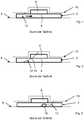
- FIGS. 1 to 3 A basic structure of such infusion or Vakuuminfusions vide is in the FIGS. 1 to 3 shown.
- a to be infiltrated with a resin component 2 of a base laminate 4 and an additional laminate 6 is placed on a tool 8 and covered by a flow aid 10.
- the laminates 4, 6 are made of dry fiber-reinforced semi-finished products and are designed as scrim, knitted fabric, or drgl.
- the flow aid 10 serves for uniform distribution of the resin in the longitudinal and width direction of the component 2 and is for example a knitted fabric or a mesh of, for example, polyester or polyamide.
- the component 2 and the flow aid 18 are packed in a vacuum bag (not shown), which is sealingly supported on the tool 8 and which is evacuated via a tool-near extraction, not shown.
- the resin is supplied via a not shown remote gate of the flow aid. According to the direction of flow of the resin indicated by the arrow, the sprue is arranged in a left-hand component area
- a flow front 12 is formed, which impregnates the base laminate 4 in the thickness direction from left to right, with the resin in the vicinity of the flow aid 10 slightly leading the resin in the vicinity of the tool 8, so that the flow front 12 in the thickness direction is formed obliquely.
- the resin is no longer stably distributed over the entire cross-section of the component 2, but is more strongly retarded in the base laminate 4 free of flow aids than in the additional auxiliary laminate 6 close to the flow path, so that virtually a kink 14 is formed in the flow front 12.
- US 2003/211194 A1 describes a structure for influencing a resin fronts course.
- an absorption layer is positioned in the region of component thickenings, by means of which the flow velocity is slowed down.
- WO 2007 / 040797A2 describes an RTM method and a corresponding structure in which a vacuum film for accelerating the flow rate and thus reducing the infiltration time of the component to be infiltrated is lifted in sections, so that the resin can flow freely over the component.
- a fixed outer housing is provided, which is positioned over the vacuum film and defines a vacuum space for lifting the vacuum film from the component between its housing wall and the vacuum film. Therefore, the flow rate is controlled by an external vacuum space.
- the object of the present invention is to provide an infusion method and a flow aid for producing a fiber-reinforced composite component, which eliminate the aforementioned disadvantages and enable a uniform or stable impregnation of the component fibers in the thickness direction.
- a flow aid for distributing a matrix material is deposited on the composite component to be infiltrated.
- the flow rate of the matrix material within the flow aid is changed at least in sections, so that the entire infusion process is stabilized and the risk of pore inclusions is minimized or eliminated.
- the propagation of the flow front can be selectively adjusted by means of a body section, so that the previously described kink formation within the flow front can be controlled.
- the body portion dissolves after a certain time.
- the flow velocity in the region of a thick-walled component section is slowed down. This makes it possible to achieve a uniform resin distribution over the entire thickness of the component, since the matrix material is guided over the component surface at at least reduced speed. Likewise, in the case of complex component structures or sections, the flow speed can at least be slowed down in order to achieve complete and stable impregnation of these component sections.
- the flow rate of the matrix material within the flow aid is increased in sections, so that, for example, the matrix material is guided faster over thin-walled component sections, since they can be soaked faster in the thickness direction.
- the flow rate is preferably at least slowed down in the rear region of the thick-walled component section, ie near the transition, so that it can be ensured that the entire component section is uniformly saturated with the matrix material.
- the matrix material in the flow aid is temporarily stopped. This ensures that only an impregnation in the thickness direction for a certain period of time is possible and the matrix material is only then passed over the component, if this is soaked to some extent in the thickness direction.
- the structure of the infusion process can be simplified if the flow aid has a body portion which serves as a kind of barrier to the matrix material and is automatically dissolved by the matrix material after a certain time.
- the body portion is dissolved by irradiation with an external energy source.
- electromagnetic radiation such as UV radiation, IR radiation and thermal radiation. That the body portion is resistant to the matrix material.
- This variant has the advantage that the dissolution of the body portion does not have to be predetermined and thus, in the course of the ongoing process, specific influence can be exerted on the course of the flow front after the assembly. Likewise, only specific areas of the body portion can be controlled individually by targeted irradiation. In this respect, this embodiment allows certain tolerances in the design and positioning of the body portion.
- Another embodiment provides that the dissolution of the body portion is initiated by irradiation with an external energy source and then propagated through the matrix material. In this way, the beginning of the resolution can be specifically determined and then the resolution itself proceeds.
- a flow aid according to the invention for an infusion process has at least one body section for changing the flow rate of the matrix material within the flow aid.
- the advantage of such a flow aid is in particular the ease of handling and positioning and the stabilization of the overall process by minimizing the risk of pore inclusion, regardless of which infusion method is chosen. A manual elaborate fragmentation of the flow aid and corresponding draping is avoided, so that in particular complex components can be made easier and cheaper.
- the body portion is formed as a barrier that temporarily stops the matrix material.
- This temporary stop function can be achieved by dissolving the body portion after, for example, the matrix material after a certain time.
- the body portion is formed by threads, which are made for example of a plastic of the group polyethersulfone (PES).
- PES group polyethersulfone
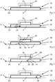
- a flow aid 18 having an integral body portion 20 which serves as a temporary barrier to a matrix material or resin flowing through the flow aid 18.
- the base material of the flow aid 18 is, for example, a polyester knit.
- the body portion 20 is formed by integral threads, for example of polyethersulfone (PES). These have the property that they are determined by a certain and adjustable time adjacent resin, for example, an epoxy or polyester resin class RTM 6, are dissolved (s. FIG. 8 ), so that the resin can continue to propagate freely within the flow aid 18.
- the time after which the body portion 20 dissolves is accurately determined in advance. This can be influenced in particular by the number, the thickness and the arrangement or orientation of the threads, the materials and the resin temperature.
- a resinous component 22 is positioned on a tool surface 24. It has, for example, at least one semifinished textile product of dry fibers as base laminate 4 and at least one second semifinished textile product of dry fibers as additional laminate 6, which is deposited centrally on base laminate 4.
- the laminates 4, 6 or semi-finished products consist for example of carbon or glass fibers, which are oriented to a scrim, a knitted fabric, a fabric or the like.
- the flow aid 18 After the positioning of the component 22 on the tool surface 24, the flow aid 18 according to the invention is deposited on it, so that the component 22 is arranged between the tool surface 24 and the flow aid 18.
- the prescribed arrangement is packed in a vacuum bag and evacuated, according to the in FIG. 5 Arrow pointing the Harzanguss in a left and the suction in a right part of the component indicated and the direction of flow of the resin indicated.
- the resin is supplied to the component 22, wherein the component 22 is saturated in the thickness direction of the resin and a flow front 26 propagates, which according to the flow direction of the resin in the flow aid 18 from left to right, ie here in Transverse direction, extends through the component 22. Due to the supply of resin via the flow aid 18, the resin in the area of the tool surface 24 is easily tracked relative to the resin in the area of the flow aid 18, so that the flow front 26 does not form parallel to the vertical axis of the component 22, but is slightly oriented.
- the resin in the region of the additional laminate or local reinforcing layers 6 is supplied via the flow aid 18, the resin distribution in the flow-aid basic laminate 6 is delayed even more, so that the flow front 26 quasi in two, via a kink 14 separate sections 28, 30th is subdivided, wherein the base laminate-side section 28 propagates more slowly than the additional laminate-side section 30, so that the flow front 18 extends in sections at very different speeds through the component 22.
- the propagation of the additional laminate side section 30 is slowed in the transverse direction, thereby improving the impregnation of the component 22 in the thickness direction, whereby the propagation speed of the base laminate side section 28 is increased.
Landscapes
- Chemical & Material Sciences (AREA)
- Engineering & Computer Science (AREA)
- Composite Materials (AREA)
- Mechanical Engineering (AREA)
- Casting Or Compression Moulding Of Plastics Or The Like (AREA)
- Reinforced Plastic Materials (AREA)
- Moulding By Coating Moulds (AREA)
Description
- Die Erfindung betrifft ein Infusionsverfahren nach dem Oberbegriff des Patentanspruchs 1 und eine Fließhilfe nach dem Oberbegriff des Patentanspruchs 8.
- Ein prinzipieller Aufbau derartiger Infusions- bzw. Vakuuminfusionsverfahren ist in den
Figuren 1 bis 3 gezeigt. Ein mit einem Harz zu infiltrierendes Bauteil 2 aus einem Grundlaminat 4 und einem Zusatzlaminat 6, ist auf einem Werkzeug 8 abgelegt und von einer Fließhilfe 10 bedeckt. Die Laminate 4, 6 bestehen aus trockenen faserverstärkten Halbzeugen und sind als Gelege, Gewirke, Gewebe oder drgl. ausgeführt. Die Fließhilfe 10 dient zur gleichmäßigen Verteilung des Harzes in Längs- und Breitenrichtung des Bauteils 2 und ist beispielsweise ein Gewirk oder ein Gitter aus beispielsweise Polyester oder Polyamid. Das Bauteil 2 und die Fließhilfe 18 werden in einem Vakuumsack (nicht gezeigt) eingepackt, der sich auf dem Werkzeug 8 dichtend abstützt und der über eine nicht gezeigte werkzeugnahen Absaugung evakuiert wird. Das Harz wird über einen nicht gezeigten werkzeugfernen Anguss der Fließhilfe zugeführt. Gemäß der durch den Pfeil angedeuteten Fließrichtung des Harzes sind der Anguss in einem linken Bauteilbereich und die Absaugung in einem rechten Bauteilbereich angeordnet. - Beim Zuführen des Harzes bildet sich eine Fließfront 12 aus, die das Grundlaminat 4 in Dickenrichtung von links nach rechts durchtränkt, wobei das Harz in der Nähe der Fließhilfe 10 dem Harz in der Nähe des Werkzeugs 8 etwas vorauseilt, so dass die Fließfront 12 in Dickenrichtung schräg ausgebildet ist. Im Bereich des Zusatzlaminates 6 liegt eine Bauteil- bzw. Laminatdickenveränderung vor, die, wie in
Figur 2 gezeigt, dazu führt, dass das Harz nicht mehr über den gesamten Querschnitt des Bauteils 2 stabil verteilt wird, sondern im fließhilfefernen Grundlaminat 4 stärker verzögert wird als im fließhilfenahen Zusatzlaminat 6, so dass quasi ein Knick 14 in der Fließfront 12 ausgebildet wird. Hierdurch besteht die Gefahr, dass, wie inFigur 3 gezeigt, sich nach dem Durchtränken des Zusatzlaminats 6 im Grundlaminat 4 unterhalb der Fließfront 12 ein Porenfeld 16 bildet, das die Qualität des herzustellenden Faserverbundbauteils 2 erheblich mindert. - Neben der Verwendung von getrennten bzw. separaten Fließhilfen, die auf dem Halbzeug bzw. dem Bauteil abgelegt werden, ist es aus der Anmeldung
DE 10 2007 013 987 A1 der Anmelderin ebenfalls bekannt, die Fließhilfe in die Werkzeugoberfläche zu integrieren. Eine gleichmäßige, unabhängig von dem Querschnitt bzw. der Dicke des Halbzeuges stabile Verteilung des Harzes lässt sich jedoch auch mit dieser Lösung nicht sicher garantieren. -
US 2003/211194 A1 beschreibt einen Aufbau zur Beeinflussung eines Harzfrontenverlaufs. Hierbei wird beispielsweise im Bereich von Bauteilverdickungen eine Absorptionsschicht positioniert, mittels der die Fließgeschwindigkeit verlangsamt wird. -
WO 2007/040797A2 beschreibt ein RTM-Verfahren und einen entsprechenden Aufbau bei dem eine Vakuumfolie zur Beschleunigung der Fließgeschwindigkeit und somit zur Reduzierung der Infiltrationszeit von dem zu infiltrierenden Bauteil abschnittsweise abgehoben wird, sodass das Harz frei über das Bauteil fließen kann. Hierzu ist ein festes Außengehäuse vorgesehen, welches über der Vakuumfolie positioniert wird und zwischen seiner Gehäusewandung und der Vakuumfolie einen Vakuumraum zum Abheben der Vakuumfolie von dem Bauteil definiert. Daher wird die Fließgeschwindigkeit durch einen externen Vakuumraum gesteuert. - Aufgabe der vorliegenden Erfindung ist es, ein Infusionsverfahren und eine Fließhilfe zur Herstellung eines faserverstärkten Verbundbauteils zu schaffen, die die vorgenannten Nachteile beseitigen und eine gleichmäßige bzw. stabile Tränkung der Bauteilfasern in Dickenrichtung ermöglichen.
- Diese Aufgabe wird gelöst durch ein Infusionsverfahren mit den Merkmalen des Patentanspruchs 1 und durch eine Fließhilfe mit den Merkmalen des Patentanspruchs 8.
- Die Erfindung wird definiert durch die Gegenstände der unabhängigen Ansprüche.
- Bei einem erfindungsgemäßen Infusionsverfahren zur Herstellung eines faserverstärkten Verbundbauteils wird eine Fließhilfe zur Verteilung eines Matrixmaterials auf dem zu infiltrierenden Verbundbauteil abgelegt. Erfindungsgemäß wird die Fließgeschwindigkeit des Matrixmaterials innerhalb der Fließhilfe zumindest abschnittsweise verändert, so dass der gesamte Infusionsprozess stabilisiert und die Gefahr von Poreneinschlüssen minimiert bzw. beseitigt wird. Die Ausbreitung der Fließfront kann mittels einem Körperabschnitt gezielt eingestellt werden, so dass die vorher beschriebene Knickbildung innerhalb der Fließfront kontrolliert werden kann. Erfindungsgemäß löst sich der Körperabschnitt dabei nach einer bestimmten Zeit auf.
- Bei einem bevorzugten Ausführungsbeispiel wird die Fließgeschwindigkeit im Bereich eines dickwandigen Bauteilabschnittes verlangsamt. Hierdurch ist es möglich, eine gleichmäßige Harzverteilung über die gesamte Dicke des Bauteils zu erreichen, da das Matrixmaterial mit zumindest reduzierter Geschwindigkeit über die Bauteiloberfläche geführt wird. Ebenso kann die Fließgeschwindigkeit bei komplexen Bauteilstrukturen bzw. -abschnitten zumindest verlangsamt werden, um eine vollständige und stabile Tränkung dieser Bauteilabschnitte zu erreichen. Bei einem anderen Ausführungsbeispiel wird die Fließgeschwindigkeit des Matrixmaterials innerhalb der Fließhilfe abschnittsweise erhöht, so dass beispielsweise das Matrixmaterial schneller über dünnwandige Bauteilabschnitte geführt wird, da diese in Dickenrichtung schneller getränkt werden können.
- Bei Übergängen von dick- auf dünnwandige Bauteilabschnitte wird die Fließgeschwindigkeit bevorzugterweise im hinteren Bereich des dickwandigen Bauteilabschnittes, d.h. nahe des Übergangs, zumindest verlangsamt, so dass sichergestellt sein kann, dass der gesamte Bauteilabschnitt gleichmäßig mit dem Matrixmaterial durchtränkt wird.
- Insbesondere ist es vorteilhaft, wenn das Matrixmaterial in der Fließhilfe temporär gestoppt wird. Hierdurch wird erreicht, dass nur eine Tränkung in Dickenrichtung für einen bestimmten Zeitraum möglich ist und das Matrixmaterial erst dann weiter über das Bauteil geführt wird, wenn dieses bis zu einem gewissen Maß in Dickenrichtung durchtränkt ist. Dabei lässt sich der Aufbau des Infusionsverfahrens vereinfachen, wenn die Fließhilfe einen Körperabschnitt aufweist, der als eine Art Barriere für das Matrixmaterial dient und nach einer bestimmten Zeit von dem Matrixmaterial selbsttätig aufgelöst wird.
- Bei einer anderen Ausführungsform wird der Körperabschnitt durch Bestrahlung mit einer externen Energiequelle aufgelöst. Beispiele sind elektromagnetische Strahlung wie UV-Strahlung, IR-Strahlung und Wärmestrahlung. D.h. der Körperabschnitt ist resistent gegenüber dem Matrixmaterial. Diese Variante hat den Vorteil, dass die Auflösung des Körperabschnitts nicht vorbestimmt werden muss und somit im laufenden Prozess nach dem Aufbau auf den Verlauf der Fließfront gezielt Einfluss genommen werden kann. Ebenso können durch gezielte Bestrahlung nur einzelne Bereiche des Körperabschnitts individuell gesteuert werden. Insofern erlaubt dieses Ausführungsbeispiel gewisse Toleranzen bei der Auslegung und Positionierung des Körperabschnitts.
- Ein weiteres Ausführungsbeispiel sieht vor, dass die Auflösung des Körperabschnitts durch Bestrahlung mit einer externen Energiequelle initiiert und dann durch das Matrixmaterial fortgeführt wird. Hierdurch kann der Beginn der Auflösung gezielt bestimmt werden und dann die Auflösung an sich selbsttätig ablaufen.
- Eine erfindungsgemäße Fließhilfe für ein Infusionsverfahren weist zumindest einen Körperabschnitt zur Veränderung der Fließgeschwindigkeit des Matrixmaterials innerhalb der Fließhilfe auf. Der Vorteil einer solchen Fließhilfe besteht insbesondere in der einfachen Handhabung und Positionierung und der Stabilisierung des Gesamtprozesses durch eine Minimierung der Gefahr von Poreneinschlüssen, unabhängig welches Infusionsverfahren gewählt wird. Ein manuelles aufwendiges Stückeln der Fließhilfe und entsprechendes Drapieren wird vermieden, so dass insbesondere komplexe Bauteile einfacher und kostengünstiger hergestellt werden können.
- Bei einem bevorzugten Ausführungsbeispiel ist der Körperabschnitt als eine Barriere ausgebildet, die das Matrixmaterial temporär stoppt. Diese temporäre Stoppfunktion kann dadurch erreicht werden, dass der Körperabschnitt nach einer bestimmten Zeit von zum Beispiel dem Matrixmaterial aufgelöst wird.
- Bei einer Variante wird der Körperabschnitt von Fäden gebildet, die beispielsweise aus einem Kunststoff der Gruppe Polyethersulfon (PES) hergestellt sind.
- Sonstige vorteilhafte Ausführungsbeispiele der vorliegenden Erfindung sind Gegenstand weiterer Unteransprüche.
- Im Folgenden werden bevorzugte Ausführungsbeispiele der Erfindung anhand schematischer Darstellungen näher erläutert. Es zeigen:
-
Figuren 1 bis 3 einen Aufbau und Verfahrensschritte eines bekannten Infusionsprozesses, und -
Figuren 4 und 8 einen Aufbau und Verfahrensschritte eines erfindungsgemäßen Infusionsprozesses. - Bei einem bevorzugten Infusionsprozess wird gemäß
Figur 4 eine Fließhilfe 18 verwendet, die einen integralen Körperabschnitt 20 aufweist, der als eine temporäre Barriere für ein durch die Fließhilfe 18 fließendes Matrixmaterial bzw. Harz dient. Das Grundmaterial der Fließhilfe 18 ist zum Beispiel ein Polyester-Gewirk. Der Körperabschnitt 20 wird hingegen von integralen Fäden, beispielsweise aus Polyethersulfon (PES) gebildet. Diese haben die Eigenschaft, dass sie nach einer bestimmen und einstellbaren Zeit von dem anliegenden Harz, beispielsweise einem Epoxid- oder Polyesterharz der Klasse RTM 6, aufgelöst werden (s.Figur 8 ), so dass sich das Harz ungehindert weiter innerhalb der Fließhilfe 18 ausbreiten kann. Die Zeit, nach der sich der Körperabschnitt 20 aufgelöst, wird im Vorfeld exakt bestimmt. Beeinflussen lässt sich dies insbesondere durch die Anzahl, der Dicke sowie der Anordnung bzw. Ausrichtung der Fäden, der Materialien und der Harztemperatur. - Im Folgenden wird ein Infusionsverfahren unter Anwendung der erfindungsgemäßen Fließhilfe 18 erläutert. Dabei wird sich jedoch nur auf die wesentlichen Merkmale bezogen und allgemein bekannte, den Aufbau eines Infusionsverfahrens betreffende Aspekte werden nicht näher erläutert. So sind zum Beispiel Abreißgewebe, Vakuumsack, Positionierung des Angusses bzw. der Absaugung, und Belüftungsgewebe nicht gezeigt und teilweise auch nicht weiter erwähnt. Dies heißt jedoch nicht, dass die erfindungsgemäße Fließhilfe 18 nur in dem hier beschriebenen Aufbau eigesetzt werden kann. Die nicht näher erwähnten Aspekte bzw. Merkmale eines Aufbaus für ein Infusionsverfahren sind jedoch Selbstverständlichkeiten. Ebenso ist es eine Selbstverständlichkeit die erfindungsgemäße Fließhilfe 18 nicht nur oberhalb eines mit dem Harz zu tränkendem Bauteils 22 anzuordnen, sondern auch unterhalb, d.h. zwischen dem Bauteil 22 und einer das Bauteil 22 aufnehmenden Werkzeugoberfläche 24. Beispielhafte Infusionstechniken sind Resin-Transfer-Molding (RTM), Vacuum-Assisted-Process (VAP), Vacuum-Resin-Infusion (VARI) und dergleichen.
- Zu Beginn des Infusionsverfahrens wird, wie in
Figur 4 gezeigt, ein mit dem Harz zu tränkendes Bauteil 22 auf einer Werkzeugoberfläche 24 positioniert. Es hat beispielsweise zumindest ein textiles Halbzeug aus trockenen Fasern als Grundlaminat 4 und zumindest ein zweites textiles Halbzeug aus trockenen Fasern als Zusatzlaminat 6, welches mittig auf dem Grundlaminat 4 abgelegt ist. Die Laminate 4, 6 bzw. Halbzeuge bestehen beispielsweise aus Kohlenstoff- oder Glasfasern, die zu einem Gelege, einem Gewirk, einem Gewebe oder dergleichen orientiert sind. - Nach der Positionierung des Bauteils 22 auf der Werkzeugoberfläche 24 wird auf diesem die erfindungsgemäße Fließhilfe 18 abgelegt, so dass das Bauteil 22 zwischen der Werkzeugoberfläche 24 und der Fließhilfe 18 angeordnet ist.
- Anschließend wird die vorgeschriebene Anordnung in einen Vakuumsack eingepackt und evakuiert, wobei gemäß dem in
Figur 5 gezeigten und die Fließrichtung des Harzes andeutenden Pfeil der Harzanguss in einem linken und die Absaugung in einem rechten Bauteilbereich erfolgt. Dann wird über die Fließhilfe 18 das Harz dem Bauteil 22 zugeführt, wobei das Bauteil 22 in Dickenrichtung von dem Harz durchtränkt wird und sich eine Fließfront 26 ausbreitet, die sich gemäß der Fließrichtung des Harzes in der Fließhilfe 18 von links nach rechts, also hier in Querrichtung, durch das Bauteil 22 erstreckt. Aufgrund der Harzzuführung über die Fließhilfe 18 wird das Harz im Bereich der Werkzeugoberfläche 24 gegenüber dem Harz im Bereich der Fließhilfe 18 leicht nachgeführt, so dass sich die Fließfront 26 nicht parallel zur Vertikalachse des Bauteils 22 ausbildet, sondern leicht angestellt orientiert ist. - Sobald, wie in
Figur 6 gezeigt, das Harz im Bereich des Zusatzlaminates bzw. lokale Verstärkungslagen 6 über die Fließhilfe 18 zugeführt wird, wird die Harzverteilung im fließhilfefernen Grundlaminat 6 noch mehr verzögert, so dass die Fließfront 26 quasi in zwei, über einen Knick 14 voneinander getrennte Abschnitte 28, 30 unterteilt wird, wobei sich der grundlaminatenseitige Abschnitt 28 langsamer ausbreitet als der zusatzlaminatseitige Abschnitt 30, so dass sich die Fließfront 18 abschnittsweise mit stark unterschiedlichen Geschwindigkeiten durch das Bauteil 22 erstreckt. - Wenn das Matrixmaterial innerhalb der Fließhilfe 18 jedoch, wie in
Figur 7 gezeigt, auf den im hinteren Bereich nahe eines Übergangs zum Grundlaminat 4 angeordneten Körperabschnitt 20 aufläuft, wird die Ausbreitung des zusatzlaminatseitigen Abschnitts 30 in Querrichtung verlangsamt und dadurch die Tränkung des Bauteils 22 in Dickenrichtung verbessert, wodurch die Ausbreitungsgeschwindigkeit des grundlaminatseitige Abschnitt 28 erhöht wird. - Sobald eine ausreichende Harmonisierung der beiden Fließfrontabschnitte 28, 30 beispielsweise über eine Einebnung bzw. eine nahezu Einebnung des Knickes 14 erreicht ist, löst sich gemäß
Figur 8 die Barriere 20 durch das bereits seit einiger Zeit anliegende und in Querrichtung gestoppte Harz selbsttätig auf, so dass eine weitere Verteilung des Harzes in Querrichtung des Bauteils 22 durch das Grundlaminat 4 möglich wird, ohne dass die Gefahr von Porenfeldern (Fi.3, 16) innerhalb des Bauteils 22 besteht. Somit wird bei Verwendung der erfindungsgemäßen Fließhilfe 18 das Bauteil 22 vollständig und gleichmäßig mit dem Harz getränkt. - Offenbart ist ein Infusionsverfahren zur Herstellung eines faserverstärkten Verbundbauteils mit einer Fließhilfe 18, wobei mittels der Fließhilfe 18 die Fließgeschwindigkeit des Matrixmaterials in einem zu infiltrierenden Bauteil 22 verändert wird, sowie eine Fließhilfe 18, die einen integralen Körperabschnitt 20 zur Veränderung der Fließgeschwindigkeit aufweist.
-
- 2
- Bauteil
- 4
- Grundlaminat
- 6
- Zusatzlaminat
- 8
- Werkzeug
- 10
- Fließhilfe
- 12
- Fließfront
- 14
- Knick
- 16
- Porenfeld
- 18
- Fließhilfe
- 20
- Körperabschnitt
- 22
- Bauteil
- 24
- Werkzeugoberfläche
- 26
- Fließfront
- 28
- Abschnitt
- 30
- Abschnitt
Claims (9)
- Infusionsverfahren zur Herstellung eines faserverstärkten Verbundbauteils (22) mit einer Fließhilfe (18) zur Verteilung eines Matrixmaterials über das zu infiltrierende Verbundbauteil (22),
wobei die Fließgeschwindigkeit des Matrixmaterials innerhalb der Fließhilfe (18) zumindest abschnittsweise verändert wird, wobei die Fließhilfe (18) einen Körperabschnitt (20) aufweist, und mittels dem Köperabschnitt (20) die Fließgeschwindigkeit verändert wird; und
dadurch gekennzeichnet, dass der Körperabschnitt (20) nach einer bestimmten Zeit aufgelöst wird. - Infusionsverfahren nach Anspruch 1, wobei die Fließgeschwindigkeit im Bereich eines dickwandigen Bauteilabschnittes (6) verlangsamt wird.
- Infusionsverfahren nach Anspruch 2, wobei die Fließgeschwindigkeit im hinteren Bereich des dickwandigen Bauteilabschnittes (6) verlangsamt wird.
- Infusionsverfahren nach Anspruch 1, 2 oder 3, wobei das Matrixmaterial in der Fließhilfe (18) temporär gestoppt wird.
- Infusionsverfahren nach Anspruch 1, wobei der Körperabschnitt (20) von dem Matrixmaterial aufgelöst wird.
- Infusionsverfahren nach Anspruch 1, wobei der Körperabschnitt (20) durch Bestrahlung aufgelöst wird.
- Infusionsverfahren nach Anspruch 1, wobei die Auflösung des Körperabschnitts (20) durch Bestrahlung initiiert und dann durch das Matrixmaterial fortgeführt wird.
- Fließhilfe (18) für ein Infusionsverfahren zur Verteilung eines Matrixmaterials über eine Oberfläche eines zu infiltrierenden Bauteils (22), wobei zumindest ein Körperabschnitt (20) zur Veränderung der Fließgeschwindigkeit des Matrixmaterials innerhalb der Fließhilfe (18) vorhanden ist;
dadurch gekennzeichnet, dass der Körperabschnitt (20) nach einer bestimmten Zeit auflösbar ist. - Fließhilfe nach Anspruch 8, wobei der Körperabschnitt (20) von Fäden gebildet ist, die beispielsweise aus einem Kunststoff der Gruppe Polyethersulfon (PES) hergestellt sind.
Applications Claiming Priority (3)
| Application Number | Priority Date | Filing Date | Title |
|---|---|---|---|
| US29051409P | 2009-12-29 | 2009-12-29 | |
| DE200910060699 DE102009060699B4 (de) | 2009-12-29 | 2009-12-29 | Infusionsverfahren und Fließhilfe |
| PCT/EP2010/070829 WO2011080288A1 (de) | 2009-12-29 | 2010-12-29 | Infusionsverfahren und fliesshilfe |
Publications (2)
| Publication Number | Publication Date |
|---|---|
| EP2519401A1 EP2519401A1 (de) | 2012-11-07 |
| EP2519401B1 true EP2519401B1 (de) | 2019-03-06 |
Family
ID=44246929
Family Applications (1)
| Application Number | Title | Priority Date | Filing Date |
|---|---|---|---|
| EP10800946.5A Not-in-force EP2519401B1 (de) | 2009-12-29 | 2010-12-29 | Infusionsverfahren und fliesshilfe |
Country Status (4)
| Country | Link |
|---|---|
| US (1) | US9156208B2 (de) |
| EP (1) | EP2519401B1 (de) |
| DE (1) | DE102009060699B4 (de) |
| WO (1) | WO2011080288A1 (de) |
Families Citing this family (10)
| Publication number | Priority date | Publication date | Assignee | Title |
|---|---|---|---|---|
| US20050048260A1 (en) * | 2003-08-27 | 2005-03-03 | The Boeing Company | Method and apparatus for fabricating a laminated fiber metal composite |
| EP2608949B1 (de) * | 2010-08-23 | 2023-03-29 | Materia, Inc. | Vartm-flussänderungen für harzsysteme mit niedriger viskosität |
| CN103328178B (zh) | 2011-02-25 | 2015-08-05 | 东丽株式会社 | Frp的制造方法 |
| EP2700492B1 (de) | 2012-08-23 | 2017-02-01 | Airbus Operations GmbH | Infusionsverfahren und Struktur für Infusionsverfahren |
| DE102014017809B4 (de) | 2014-12-03 | 2017-03-23 | Audi Ag | Verfahren zur Herstellung eines Strukturbauteils |
| DE102014118670B4 (de) | 2014-12-15 | 2016-06-30 | Benteler Sgl Gmbh & Co. Kg | RTM-Verfahren mit Zwischenfaserschicht |
| DE102015005492B4 (de) | 2015-04-30 | 2023-05-04 | Airbus Defence and Space GmbH | Fließhilfe für einen Infusionsaufbau sowie Infusionsaufbau und Verfahren zum Infiltrieren eines Fasermaterials |
| CN109070500B (zh) | 2016-03-25 | 2021-04-20 | 肖特兄弟公司 | 用于制备复合层合物的设备和方法 |
| AU2016203751B2 (en) * | 2016-06-06 | 2022-01-20 | The Boeing Company | Method and system for resin infusing a composite preform |
| GB202020936D0 (en) | 2020-12-23 | 2021-02-17 | Lm Wind Power As | Method of manufacturing a wind turbine blade |
Citations (1)
| Publication number | Priority date | Publication date | Assignee | Title |
|---|---|---|---|---|
| WO2007040797A2 (en) * | 2005-09-22 | 2007-04-12 | University Of Delaware | Vacuum assisted resin transfer molding techniques with flow flooding chamber |
Family Cites Families (30)
| Publication number | Priority date | Publication date | Assignee | Title |
|---|---|---|---|---|
| US2913036A (en) * | 1956-08-10 | 1959-11-17 | Anthony Bros Fibre Glass Pool | Process and apparatus for molding large plastic structures |
| US3137750A (en) * | 1960-03-14 | 1964-06-16 | Saint Gobain | Injection molding of fabric reinforced plastics |
| US4963215A (en) * | 1987-12-07 | 1990-10-16 | The Boeing Company | Method for debulking precured thermoplastic composite laminae |
| US4873044A (en) * | 1987-12-21 | 1989-10-10 | Shell Oil Company | Method and apparatus for reduction of mold cycle time |
| US4902215A (en) * | 1988-06-08 | 1990-02-20 | Seemann Iii William H | Plastic transfer molding techniques for the production of fiber reinforced plastic structures |
| JP2807891B2 (ja) * | 1989-02-28 | 1998-10-08 | 三菱レイヨン株式会社 | プリプレグ及びその製造法 |
| US5242651A (en) * | 1990-07-25 | 1993-09-07 | Vought Aircraft Company | Pressure balanced processing of composite structures |
| GB9212697D0 (en) * | 1992-06-15 | 1992-07-29 | Short Brothers Plc | Composite structure manufacture |
| US6919039B2 (en) * | 1995-03-28 | 2005-07-19 | Eric J. Lang | Channel assisted resin transfer molding |
| US5958325A (en) * | 1995-06-07 | 1999-09-28 | Tpi Technology, Inc. | Large composite structures and a method for production of large composite structures incorporating a resin distribution network |
| US5971742A (en) * | 1996-09-18 | 1999-10-26 | Pyramid Composites Manufacturing Limited Partnership | Apparatus for molding composite articles |
| US6506325B1 (en) * | 1999-02-05 | 2003-01-14 | The B. F. Goodrich Company | Method controlling the exotherm of a vacuum resin infusion |
| US7081219B2 (en) * | 1999-03-18 | 2006-07-25 | Stewart David H | Method and machine for manufacturing molded structures using zoned pressure molding |
| DE19925588A1 (de) * | 1999-06-04 | 2000-12-07 | Deutsch Zentr Luft & Raumfahrt | Faden zur Verbindung von Fasern eines Faserhalbzeuges sowie Faserhalbzeug, und Verfahren zur Herstellung von Faserverbundwerkstoffen |
| US6818159B2 (en) * | 2000-03-17 | 2004-11-16 | Deutsches Zentrum Fuer Luft-Und Raumfahrt E.V. | Process for the production of a composite consisting of a fiber reinforced material |
| GB0020630D0 (en) * | 2000-08-22 | 2000-10-11 | Cytec Tech Corp | Support structure or carrier for a curable composition |
| US7060156B2 (en) * | 2001-07-23 | 2006-06-13 | Vrac, Llc | Three-dimensional spacer fabric resin interlaminar infusion media process and vacuum-induced reinforcing composite laminate structures |
| US6630095B2 (en) * | 2001-08-01 | 2003-10-07 | Lockheed Martin Corporation | Method for making composite structures |
| US6964561B2 (en) * | 2002-04-23 | 2005-11-15 | V System Composites, Inc. | High-performance infusion system for VARTM fabrication |
| ES2391450T3 (es) * | 2002-05-29 | 2012-11-26 | The Boeing Company | Proceso de infusión controlada de resina a presión atmosférica |
| GB0229094D0 (en) * | 2002-12-13 | 2003-01-15 | Hexcel Composites Ltd | Improvements in or relating to the preparation of fibre-reinforced composites |
| US7300894B2 (en) * | 2002-12-30 | 2007-11-27 | University Of Maine | Composites pressure resin infusion system (ComPRIS) |
| US20050257887A1 (en) * | 2004-05-24 | 2005-11-24 | Tsotsis Thomas K | Method and apparatus for melt-bonded materials for tackification of dry fabric preforms |
| DE10326021A1 (de) * | 2003-06-02 | 2004-12-30 | Deutsches Zentrum für Luft- und Raumfahrt e.V. | Verfahren zur Überwachung der Herstellung eines Bauteils aus einem faserverstärkten Werkstoff |
| US20050037678A1 (en) * | 2003-08-11 | 2005-02-17 | Mack Patrick E. | Open grid fabric resin infusion media and reinforcing composite lamina |
| WO2006121961A1 (en) * | 2005-05-09 | 2006-11-16 | Cytec Technology Corp. | Resin-soluble thermoplastic veil for composite materials |
| DE102007013987A1 (de) * | 2006-08-17 | 2008-02-21 | Airbus Deutschland Gmbh | Werkzeug zur Herstellung von Faserverbundbauteilen |
| BRPI0809269B8 (pt) | 2007-03-20 | 2023-03-28 | Mitsubishi Heavy Ind Ltd | Método de rtm auxiliada com vácuo, e método para produzir um produto moldado de plástico reforçado com fibra |
| EP2608949B1 (de) * | 2010-08-23 | 2023-03-29 | Materia, Inc. | Vartm-flussänderungen für harzsysteme mit niedriger viskosität |
| EP2628764A1 (de) * | 2012-02-14 | 2013-08-21 | Siemens Aktiengesellschaft | Verfahren zur Herstellung eines faserverstärkten Verbundstoffs |
-
2009
- 2009-12-29 DE DE200910060699 patent/DE102009060699B4/de not_active Expired - Fee Related
-
2010
- 2010-12-29 US US13/519,935 patent/US9156208B2/en active Active
- 2010-12-29 WO PCT/EP2010/070829 patent/WO2011080288A1/de not_active Ceased
- 2010-12-29 EP EP10800946.5A patent/EP2519401B1/de not_active Not-in-force
Patent Citations (1)
| Publication number | Priority date | Publication date | Assignee | Title |
|---|---|---|---|---|
| WO2007040797A2 (en) * | 2005-09-22 | 2007-04-12 | University Of Delaware | Vacuum assisted resin transfer molding techniques with flow flooding chamber |
Also Published As
| Publication number | Publication date |
|---|---|
| EP2519401A1 (de) | 2012-11-07 |
| DE102009060699A1 (de) | 2011-06-30 |
| US9156208B2 (en) | 2015-10-13 |
| US20130099426A1 (en) | 2013-04-25 |
| WO2011080288A1 (de) | 2011-07-07 |
| DE102009060699B4 (de) | 2014-07-03 |
Similar Documents
| Publication | Publication Date | Title |
|---|---|---|
| DE102009060699B4 (de) | Infusionsverfahren und Fließhilfe | |
| DE10013409C1 (de) | Verfahren und Vorrichtung zur Herstellung von faserverstärkten Bauteilen mittels eines Injektionsverfahrens | |
| EP1420940B1 (de) | Verfahren und vorrichtung zur herstellung von faserverstärkten bauteilen mittels eines injektionsverfahrens | |
| EP2700493B1 (de) | Vakuuminfusionsverfahren und Vorrichtung dafür | |
| DE4208670C2 (de) | Verfahren zur Herstellung von Trägern aus faserverstärkten Kunststoffen für Kraftfahrzeug-Stoßfänger sowie derartige Träger | |
| EP2567807B1 (de) | Verfahren zur Herstellung eines Windenergieanlagenrotorblattbauteils mit einem vorgefertigten Hauptgurt | |
| EP2234795B1 (de) | Mehrlagiges, flexibles flächenmaterial | |
| DE102007060739B4 (de) | Verfahren und Vorrichtung zur Herstellung von Faserverbundbauteilen | |
| EP2561977B1 (de) | Verfahren zur Herstellung eines Windenergieanlagenrotorblattteils mit einem kohlenstofffaserverstärkten Hauptgurt | |
| DE102008014657A1 (de) | Verfahren zur Herstellung von Faserverbundbauteilen | |
| DE102012004168A1 (de) | Verfahren zum Spritzgießen von Hohlkörpern mit Endlosfaser-Verstärkungselementen | |
| DE102008001468A1 (de) | Verfahren zum Beschichten eines Faserverbundbauteils für ein Luft- oder Raumfahrzeug und durch ein derartiges Verfahren hergestelltes Faserverbundbauteil | |
| DE102008011658A1 (de) | Verfahren zum Herstellen eines Faserverbund-Bauteils und Faserverbund-Bauteil | |
| EP4017712B1 (de) | Verfahren zum herstellen eines bauteils aus einem faserverbundwerkstoff | |
| DE102017128501A1 (de) | Verfahren zum Herstellen eines Verbundbauteils | |
| DE102020133803A1 (de) | Prozessanordnung sowie Verfahren zur Herstellung eines Endlosprofils aus Faserverbundkunststoff | |
| DE102015007284B4 (de) | Verfahren zur Herstellung von Faserverbundbauteilen | |
| EP1484164B1 (de) | Verfahren zum Verkleben von Bauteilen und insbesondere von Faserverbundbauteilen | |
| DE102014205896A1 (de) | Verfahren zur Herstellung eines Bauteils aus Organoblech und Werkzeug | |
| DE102011107512B4 (de) | Duktile CFK-Struktur | |
| DE102020206045A1 (de) | Verfahren zur Herstellung eines Hohlkörper-Verbundbauteils, sowie Projektil zum Einsatz in einem solchen Verfahren | |
| DE10356135A1 (de) | Verfahren zur Herstellung eines Bauteils aus einem Faserverbundwerkstoff | |
| DE102013009745A1 (de) | Profilelement, insbesondere für einen Kraftwagen, sowie Verfahren zum Herstellen eines solchen Profilelements | |
| EP3647039B1 (de) | Verfahren zum herstellen eines bereichsweise flächigen bauteils aus einem faserverbundwerkstoff | |
| EP3512682A1 (de) | Lokale verstärkung von spritzgussbauteilen |
Legal Events
| Date | Code | Title | Description |
|---|---|---|---|
| PUAI | Public reference made under article 153(3) epc to a published international application that has entered the european phase |
Free format text: ORIGINAL CODE: 0009012 |
|
| 17P | Request for examination filed |
Effective date: 20120704 |
|
| AK | Designated contracting states |
Kind code of ref document: A1 Designated state(s): AL AT BE BG CH CY CZ DE DK EE ES FI FR GB GR HR HU IE IS IT LI LT LU LV MC MK MT NL NO PL PT RO RS SE SI SK SM TR |
|
| DAX | Request for extension of the european patent (deleted) | ||
| 17Q | First examination report despatched |
Effective date: 20160615 |
|
| STAA | Information on the status of an ep patent application or granted ep patent |
Free format text: STATUS: EXAMINATION IS IN PROGRESS |
|
| GRAP | Despatch of communication of intention to grant a patent |
Free format text: ORIGINAL CODE: EPIDOSNIGR1 |
|
| STAA | Information on the status of an ep patent application or granted ep patent |
Free format text: STATUS: GRANT OF PATENT IS INTENDED |
|
| RIC1 | Information provided on ipc code assigned before grant |
Ipc: B29C 70/44 20060101AFI20180703BHEP Ipc: B29C 70/54 20060101ALI20180703BHEP Ipc: B29C 70/02 20060101ALI20180703BHEP |
|
| INTG | Intention to grant announced |
Effective date: 20180730 |
|
| GRAJ | Information related to disapproval of communication of intention to grant by the applicant or resumption of examination proceedings by the epo deleted |
Free format text: ORIGINAL CODE: EPIDOSDIGR1 |
|
| STAA | Information on the status of an ep patent application or granted ep patent |
Free format text: STATUS: EXAMINATION IS IN PROGRESS |
|
| GRAP | Despatch of communication of intention to grant a patent |
Free format text: ORIGINAL CODE: EPIDOSNIGR1 |
|
| STAA | Information on the status of an ep patent application or granted ep patent |
Free format text: STATUS: GRANT OF PATENT IS INTENDED |
|
| INTC | Intention to grant announced (deleted) | ||
| RBV | Designated contracting states (corrected) |
Designated state(s): AL AT BE BG CH CY CZ DK EE ES FI FR GB GR HR HU IE IS IT LI LT LU LV MC MK MT NL NO PL PT RO RS SE SI SK SM TR |
|
| REG | Reference to a national code |
Ref country code: DE Ref legal event code: R108 |
|
| INTG | Intention to grant announced |
Effective date: 20181102 |
|
| GRAS | Grant fee paid |
Free format text: ORIGINAL CODE: EPIDOSNIGR3 |
|
| GRAA | (expected) grant |
Free format text: ORIGINAL CODE: 0009210 |
|
| STAA | Information on the status of an ep patent application or granted ep patent |
Free format text: STATUS: THE PATENT HAS BEEN GRANTED |
|
| AK | Designated contracting states |
Kind code of ref document: B1 Designated state(s): AL AT BE BG CH CY CZ DK EE ES FI FR GB GR HR HU IE IS IT LI LT LU LV MC MK MT NL NO PL PT RO RS SE SI SK SM TR |
|
| REG | Reference to a national code |
Ref country code: GB Ref legal event code: FG4D Free format text: NOT ENGLISH |
|
| REG | Reference to a national code |
Ref country code: CH Ref legal event code: EP Ref country code: AT Ref legal event code: REF Ref document number: 1103967 Country of ref document: AT Kind code of ref document: T Effective date: 20190315 |
|
| REG | Reference to a national code |
Ref country code: IE Ref legal event code: FG4D Free format text: LANGUAGE OF EP DOCUMENT: GERMAN |
|
| REG | Reference to a national code |
Ref country code: NL Ref legal event code: MP Effective date: 20190306 |
|
| REG | Reference to a national code |
Ref country code: LT Ref legal event code: MG4D |
|
| PG25 | Lapsed in a contracting state [announced via postgrant information from national office to epo] |
Ref country code: LT Free format text: LAPSE BECAUSE OF FAILURE TO SUBMIT A TRANSLATION OF THE DESCRIPTION OR TO PAY THE FEE WITHIN THE PRESCRIBED TIME-LIMIT Effective date: 20190306 Ref country code: FI Free format text: LAPSE BECAUSE OF FAILURE TO SUBMIT A TRANSLATION OF THE DESCRIPTION OR TO PAY THE FEE WITHIN THE PRESCRIBED TIME-LIMIT Effective date: 20190306 Ref country code: SE Free format text: LAPSE BECAUSE OF FAILURE TO SUBMIT A TRANSLATION OF THE DESCRIPTION OR TO PAY THE FEE WITHIN THE PRESCRIBED TIME-LIMIT Effective date: 20190306 Ref country code: NO Free format text: LAPSE BECAUSE OF FAILURE TO SUBMIT A TRANSLATION OF THE DESCRIPTION OR TO PAY THE FEE WITHIN THE PRESCRIBED TIME-LIMIT Effective date: 20190606 |
|
| PG25 | Lapsed in a contracting state [announced via postgrant information from national office to epo] |
Ref country code: BG Free format text: LAPSE BECAUSE OF FAILURE TO SUBMIT A TRANSLATION OF THE DESCRIPTION OR TO PAY THE FEE WITHIN THE PRESCRIBED TIME-LIMIT Effective date: 20190606 Ref country code: HR Free format text: LAPSE BECAUSE OF FAILURE TO SUBMIT A TRANSLATION OF THE DESCRIPTION OR TO PAY THE FEE WITHIN THE PRESCRIBED TIME-LIMIT Effective date: 20190306 Ref country code: GR Free format text: LAPSE BECAUSE OF FAILURE TO SUBMIT A TRANSLATION OF THE DESCRIPTION OR TO PAY THE FEE WITHIN THE PRESCRIBED TIME-LIMIT Effective date: 20190607 Ref country code: LV Free format text: LAPSE BECAUSE OF FAILURE TO SUBMIT A TRANSLATION OF THE DESCRIPTION OR TO PAY THE FEE WITHIN THE PRESCRIBED TIME-LIMIT Effective date: 20190306 Ref country code: RS Free format text: LAPSE BECAUSE OF FAILURE TO SUBMIT A TRANSLATION OF THE DESCRIPTION OR TO PAY THE FEE WITHIN THE PRESCRIBED TIME-LIMIT Effective date: 20190306 Ref country code: NL Free format text: LAPSE BECAUSE OF FAILURE TO SUBMIT A TRANSLATION OF THE DESCRIPTION OR TO PAY THE FEE WITHIN THE PRESCRIBED TIME-LIMIT Effective date: 20190306 |
|
| PG25 | Lapsed in a contracting state [announced via postgrant information from national office to epo] |
Ref country code: IT Free format text: LAPSE BECAUSE OF FAILURE TO SUBMIT A TRANSLATION OF THE DESCRIPTION OR TO PAY THE FEE WITHIN THE PRESCRIBED TIME-LIMIT Effective date: 20190306 Ref country code: CZ Free format text: LAPSE BECAUSE OF FAILURE TO SUBMIT A TRANSLATION OF THE DESCRIPTION OR TO PAY THE FEE WITHIN THE PRESCRIBED TIME-LIMIT Effective date: 20190306 Ref country code: SK Free format text: LAPSE BECAUSE OF FAILURE TO SUBMIT A TRANSLATION OF THE DESCRIPTION OR TO PAY THE FEE WITHIN THE PRESCRIBED TIME-LIMIT Effective date: 20190306 Ref country code: RO Free format text: LAPSE BECAUSE OF FAILURE TO SUBMIT A TRANSLATION OF THE DESCRIPTION OR TO PAY THE FEE WITHIN THE PRESCRIBED TIME-LIMIT Effective date: 20190306 Ref country code: ES Free format text: LAPSE BECAUSE OF FAILURE TO SUBMIT A TRANSLATION OF THE DESCRIPTION OR TO PAY THE FEE WITHIN THE PRESCRIBED TIME-LIMIT Effective date: 20190306 Ref country code: EE Free format text: LAPSE BECAUSE OF FAILURE TO SUBMIT A TRANSLATION OF THE DESCRIPTION OR TO PAY THE FEE WITHIN THE PRESCRIBED TIME-LIMIT Effective date: 20190306 Ref country code: PT Free format text: LAPSE BECAUSE OF FAILURE TO SUBMIT A TRANSLATION OF THE DESCRIPTION OR TO PAY THE FEE WITHIN THE PRESCRIBED TIME-LIMIT Effective date: 20190706 Ref country code: AL Free format text: LAPSE BECAUSE OF FAILURE TO SUBMIT A TRANSLATION OF THE DESCRIPTION OR TO PAY THE FEE WITHIN THE PRESCRIBED TIME-LIMIT Effective date: 20190306 |
|
| PG25 | Lapsed in a contracting state [announced via postgrant information from national office to epo] |
Ref country code: SM Free format text: LAPSE BECAUSE OF FAILURE TO SUBMIT A TRANSLATION OF THE DESCRIPTION OR TO PAY THE FEE WITHIN THE PRESCRIBED TIME-LIMIT Effective date: 20190306 Ref country code: PL Free format text: LAPSE BECAUSE OF FAILURE TO SUBMIT A TRANSLATION OF THE DESCRIPTION OR TO PAY THE FEE WITHIN THE PRESCRIBED TIME-LIMIT Effective date: 20190306 |
|
| PG25 | Lapsed in a contracting state [announced via postgrant information from national office to epo] |
Ref country code: IS Free format text: LAPSE BECAUSE OF FAILURE TO SUBMIT A TRANSLATION OF THE DESCRIPTION OR TO PAY THE FEE WITHIN THE PRESCRIBED TIME-LIMIT Effective date: 20190706 |
|
| PLBE | No opposition filed within time limit |
Free format text: ORIGINAL CODE: 0009261 |
|
| STAA | Information on the status of an ep patent application or granted ep patent |
Free format text: STATUS: NO OPPOSITION FILED WITHIN TIME LIMIT |
|
| PG25 | Lapsed in a contracting state [announced via postgrant information from national office to epo] |
Ref country code: DK Free format text: LAPSE BECAUSE OF FAILURE TO SUBMIT A TRANSLATION OF THE DESCRIPTION OR TO PAY THE FEE WITHIN THE PRESCRIBED TIME-LIMIT Effective date: 20190306 |
|
| 26N | No opposition filed |
Effective date: 20191209 |
|
| PG25 | Lapsed in a contracting state [announced via postgrant information from national office to epo] |
Ref country code: SI Free format text: LAPSE BECAUSE OF FAILURE TO SUBMIT A TRANSLATION OF THE DESCRIPTION OR TO PAY THE FEE WITHIN THE PRESCRIBED TIME-LIMIT Effective date: 20190306 |
|
| PGFP | Annual fee paid to national office [announced via postgrant information from national office to epo] |
Ref country code: FR Payment date: 20191220 Year of fee payment: 10 |
|
| PG25 | Lapsed in a contracting state [announced via postgrant information from national office to epo] |
Ref country code: TR Free format text: LAPSE BECAUSE OF FAILURE TO SUBMIT A TRANSLATION OF THE DESCRIPTION OR TO PAY THE FEE WITHIN THE PRESCRIBED TIME-LIMIT Effective date: 20190306 |
|
| PGFP | Annual fee paid to national office [announced via postgrant information from national office to epo] |
Ref country code: GB Payment date: 20191220 Year of fee payment: 10 |
|
| REG | Reference to a national code |
Ref country code: CH Ref legal event code: PL |
|
| REG | Reference to a national code |
Ref country code: BE Ref legal event code: MM Effective date: 20191231 |
|
| PG25 | Lapsed in a contracting state [announced via postgrant information from national office to epo] |
Ref country code: MC Free format text: LAPSE BECAUSE OF FAILURE TO SUBMIT A TRANSLATION OF THE DESCRIPTION OR TO PAY THE FEE WITHIN THE PRESCRIBED TIME-LIMIT Effective date: 20190306 |
|
| PG25 | Lapsed in a contracting state [announced via postgrant information from national office to epo] |
Ref country code: IE Free format text: LAPSE BECAUSE OF NON-PAYMENT OF DUE FEES Effective date: 20191229 Ref country code: LU Free format text: LAPSE BECAUSE OF NON-PAYMENT OF DUE FEES Effective date: 20191229 |
|
| PG25 | Lapsed in a contracting state [announced via postgrant information from national office to epo] |
Ref country code: BE Free format text: LAPSE BECAUSE OF NON-PAYMENT OF DUE FEES Effective date: 20191231 Ref country code: CH Free format text: LAPSE BECAUSE OF NON-PAYMENT OF DUE FEES Effective date: 20191231 Ref country code: LI Free format text: LAPSE BECAUSE OF NON-PAYMENT OF DUE FEES Effective date: 20191231 |
|
| REG | Reference to a national code |
Ref country code: AT Ref legal event code: MM01 Ref document number: 1103967 Country of ref document: AT Kind code of ref document: T Effective date: 20191229 |
|
| PG25 | Lapsed in a contracting state [announced via postgrant information from national office to epo] |
Ref country code: CY Free format text: LAPSE BECAUSE OF FAILURE TO SUBMIT A TRANSLATION OF THE DESCRIPTION OR TO PAY THE FEE WITHIN THE PRESCRIBED TIME-LIMIT Effective date: 20190306 Ref country code: AT Free format text: LAPSE BECAUSE OF NON-PAYMENT OF DUE FEES Effective date: 20191229 |
|
| PG25 | Lapsed in a contracting state [announced via postgrant information from national office to epo] |
Ref country code: MT Free format text: LAPSE BECAUSE OF FAILURE TO SUBMIT A TRANSLATION OF THE DESCRIPTION OR TO PAY THE FEE WITHIN THE PRESCRIBED TIME-LIMIT Effective date: 20190306 Ref country code: HU Free format text: LAPSE BECAUSE OF FAILURE TO SUBMIT A TRANSLATION OF THE DESCRIPTION OR TO PAY THE FEE WITHIN THE PRESCRIBED TIME-LIMIT; INVALID AB INITIO Effective date: 20101229 |
|
| GBPC | Gb: european patent ceased through non-payment of renewal fee |
Effective date: 20201229 |
|
| PG25 | Lapsed in a contracting state [announced via postgrant information from national office to epo] |
Ref country code: FR Free format text: LAPSE BECAUSE OF NON-PAYMENT OF DUE FEES Effective date: 20201231 |
|
| PG25 | Lapsed in a contracting state [announced via postgrant information from national office to epo] |
Ref country code: GB Free format text: LAPSE BECAUSE OF NON-PAYMENT OF DUE FEES Effective date: 20201229 |
|
| PG25 | Lapsed in a contracting state [announced via postgrant information from national office to epo] |
Ref country code: MK Free format text: LAPSE BECAUSE OF FAILURE TO SUBMIT A TRANSLATION OF THE DESCRIPTION OR TO PAY THE FEE WITHIN THE PRESCRIBED TIME-LIMIT Effective date: 20190306 |