EP2519012A2 - Display panel, display device, and electronic unit - Google Patents
Display panel, display device, and electronic unit Download PDFInfo
- Publication number
- EP2519012A2 EP2519012A2 EP20120164910 EP12164910A EP2519012A2 EP 2519012 A2 EP2519012 A2 EP 2519012A2 EP 20120164910 EP20120164910 EP 20120164910 EP 12164910 A EP12164910 A EP 12164910A EP 2519012 A2 EP2519012 A2 EP 2519012A2
- Authority
- EP
- European Patent Office
- Prior art keywords
- pixels
- section
- light
- transmissive regions
- sub
- Prior art date
- Legal status (The legal status is an assumption and is not a legal conclusion. Google has not performed a legal analysis and makes no representation as to the accuracy of the status listed.)
- Granted
Links
Images




Classifications
-
- H—ELECTRICITY
- H05—ELECTRIC TECHNIQUES NOT OTHERWISE PROVIDED FOR
- H05B—ELECTRIC HEATING; ELECTRIC LIGHT SOURCES NOT OTHERWISE PROVIDED FOR; CIRCUIT ARRANGEMENTS FOR ELECTRIC LIGHT SOURCES, IN GENERAL
- H05B33/00—Electroluminescent light sources
- H05B33/12—Light sources with substantially two-dimensional [2D] radiating surfaces
- H05B33/22—Light sources with substantially two-dimensional [2D] radiating surfaces characterised by the chemical or physical composition or the arrangement of auxiliary dielectric or reflective layers
-
- G—PHYSICS
- G02—OPTICS
- G02B—OPTICAL ELEMENTS, SYSTEMS OR APPARATUS
- G02B30/00—Optical systems or apparatus for producing three-dimensional [3D] effects, e.g. stereoscopic images
- G02B30/20—Optical systems or apparatus for producing three-dimensional [3D] effects, e.g. stereoscopic images by providing first and second parallax images to an observer's left and right eyes
- G02B30/26—Optical systems or apparatus for producing three-dimensional [3D] effects, e.g. stereoscopic images by providing first and second parallax images to an observer's left and right eyes of the autostereoscopic type
- G02B30/27—Optical systems or apparatus for producing three-dimensional [3D] effects, e.g. stereoscopic images by providing first and second parallax images to an observer's left and right eyes of the autostereoscopic type involving lenticular arrays
-
- G—PHYSICS
- G02—OPTICS
- G02B—OPTICAL ELEMENTS, SYSTEMS OR APPARATUS
- G02B30/00—Optical systems or apparatus for producing three-dimensional [3D] effects, e.g. stereoscopic images
- G02B30/20—Optical systems or apparatus for producing three-dimensional [3D] effects, e.g. stereoscopic images by providing first and second parallax images to an observer's left and right eyes
- G02B30/26—Optical systems or apparatus for producing three-dimensional [3D] effects, e.g. stereoscopic images by providing first and second parallax images to an observer's left and right eyes of the autostereoscopic type
- G02B30/30—Optical systems or apparatus for producing three-dimensional [3D] effects, e.g. stereoscopic images by providing first and second parallax images to an observer's left and right eyes of the autostereoscopic type involving parallax barriers
-
- G—PHYSICS
- G09—EDUCATION; CRYPTOGRAPHY; DISPLAY; ADVERTISING; SEALS
- G09G—ARRANGEMENTS OR CIRCUITS FOR CONTROL OF INDICATING DEVICES USING STATIC MEANS TO PRESENT VARIABLE INFORMATION
- G09G3/00—Control arrangements or circuits, of interest only in connection with visual indicators other than cathode-ray tubes
- G09G3/20—Control arrangements or circuits, of interest only in connection with visual indicators other than cathode-ray tubes for presentation of an assembly of a number of characters, e.g. a page, by composing the assembly by combination of individual elements arranged in a matrix no fixed position being assigned to or needed to be assigned to the individual characters or partial characters
- G09G3/22—Control arrangements or circuits, of interest only in connection with visual indicators other than cathode-ray tubes for presentation of an assembly of a number of characters, e.g. a page, by composing the assembly by combination of individual elements arranged in a matrix no fixed position being assigned to or needed to be assigned to the individual characters or partial characters using controlled light sources
- G09G3/30—Control arrangements or circuits, of interest only in connection with visual indicators other than cathode-ray tubes for presentation of an assembly of a number of characters, e.g. a page, by composing the assembly by combination of individual elements arranged in a matrix no fixed position being assigned to or needed to be assigned to the individual characters or partial characters using controlled light sources using electroluminescent panels
-
- H—ELECTRICITY
- H04—ELECTRIC COMMUNICATION TECHNIQUE
- H04N—PICTORIAL COMMUNICATION, e.g. TELEVISION
- H04N13/00—Stereoscopic video systems; Multi-view video systems; Details thereof
- H04N13/30—Image reproducers
- H04N13/302—Image reproducers for viewing without the aid of special glasses, i.e. using autostereoscopic displays
- H04N13/31—Image reproducers for viewing without the aid of special glasses, i.e. using autostereoscopic displays using parallax barriers
-
- H—ELECTRICITY
- H04—ELECTRIC COMMUNICATION TECHNIQUE
- H04N—PICTORIAL COMMUNICATION, e.g. TELEVISION
- H04N13/00—Stereoscopic video systems; Multi-view video systems; Details thereof
- H04N13/30—Image reproducers
- H04N13/324—Colour aspects
-
- H—ELECTRICITY
- H05—ELECTRIC TECHNIQUES NOT OTHERWISE PROVIDED FOR
- H05B—ELECTRIC HEATING; ELECTRIC LIGHT SOURCES NOT OTHERWISE PROVIDED FOR; CIRCUIT ARRANGEMENTS FOR ELECTRIC LIGHT SOURCES, IN GENERAL
- H05B33/00—Electroluminescent light sources
- H05B33/02—Details
- H05B33/06—Electrode terminals
-
- H—ELECTRICITY
- H05—ELECTRIC TECHNIQUES NOT OTHERWISE PROVIDED FOR
- H05B—ELECTRIC HEATING; ELECTRIC LIGHT SOURCES NOT OTHERWISE PROVIDED FOR; CIRCUIT ARRANGEMENTS FOR ELECTRIC LIGHT SOURCES, IN GENERAL
- H05B33/00—Electroluminescent light sources
- H05B33/12—Light sources with substantially two-dimensional [2D] radiating surfaces
-
- G—PHYSICS
- G02—OPTICS
- G02B—OPTICAL ELEMENTS, SYSTEMS OR APPARATUS
- G02B2207/00—Coding scheme for general features or characteristics of optical elements and systems of subclass G02B, but not including elements and systems which would be classified in G02B6/00 and subgroups
- G02B2207/123—Optical louvre elements, e.g. for directional light blocking
-
- G—PHYSICS
- G09—EDUCATION; CRYPTOGRAPHY; DISPLAY; ADVERTISING; SEALS
- G09G—ARRANGEMENTS OR CIRCUITS FOR CONTROL OF INDICATING DEVICES USING STATIC MEANS TO PRESENT VARIABLE INFORMATION
- G09G2300/00—Aspects of the constitution of display devices
- G09G2300/04—Structural and physical details of display devices
- G09G2300/0439—Pixel structures
- G09G2300/0443—Pixel structures with several sub-pixels for the same colour in a pixel, not specifically used to display gradations
Definitions
- the present disclosure relates to a display panel, display device, and electronic unit.
- a display device capable of multi-view display or three-dimensional (3D) display has been recently in practical use.
- Such a display device is known to include a barrier layer on a display region of a display panel, for example.
- a barrier layer As an exemplary barrier layer, Japanese Unexamined Patent Application Publication No. 9-281440 describes a barrier layer including a plurality of transmissive slits each separated by a light-blocking region.
- Japanese Unexamined Patent Application Publication No. 8-106070 describes a barrier liquid crystal display with which a light-blocking region is generated in response to application of a voltage to a liquid crystal material.
- the slits thereof are sometimes reduced in width to be equal to that of a sub-pixel. If this is the case, however, the distance between the pixels and the barrier layer is reduced, and this results in a smaller processing margin at the time of processing a CF (Color Filter) substrate of a display panel until the thickness thereof becomes suitable for the distance.
- a possibility is to increase the slit width to be equal to the width of two or more sub-pixels. If the width is increased as such, however, a phenomenon of color moiré may occur when the display panel is viewed from a direction that is not an appropriate-viewing direction.
- the "color moiré" is a phenomenon observed when the direction of viewing the display panel is changed by degrees in the horizontal plane, and is caused by the resulting similarity of color appearing in the slits and color disappearing therefrom, whereby this looks like glare.
- a display panel capable of suppressing degradation of the image quality at the time of multi-view display
- a display device provided with the display panel, and an electronic unit provided with the display device.
- Examples of the disclosure can provide multi-view display allowing viewing of two-dimensional (2D) image (planar image) that looks different depending on from which perspective the image is viewed.
- the present technology relates also to a display device provided with a display panel, and an electronic unit provided with the display device described above.
- a display panel including: a panel section including a display region where a plurality of pixels are arranged, and a gap region provided in a gap between the pixels; and a barrier section including a plurality of transmissive regions in a two-dimensional arrangement, and a light-blocking region to be around each of the transmissive regions.
- the transmissive regions are each configured to make entirely visible any one of the pixels therethrough when a viewer views the panel section not from a front but from a first or second direction via the barrier section, the pixels are each configured by a plurality of sub-pixels varying in type, and the sub-pixels in each of the pixels are arranged not in stripes but differently.
- a display device including: a panel section including a display region where a plurality of pixels are arranged, and a gap region provided in a gap between the pixels; a barrier section including a plurality of transmissive regions in a two-dimensional arrangement, and a light-blocking region to be around each of the transmissive regions; and a drive section driving the panel section or both the panel section and the barrier section.
- the transmissive regions are each of a size allowing viewing of any one of the pixels entirely therethrough when a viewer views the panel section not from a front but from a first or second direction via the barrier section, the pixels are each configured by a plurality of sub-pixels varying in type, and the sub-pixels in each of the pixels are arranged not in stripes but differently.
- an electronic unit with a display device including: a panel section including a display region where a plurality of pixels are arranged, and a gap region provided in a gap between the pixels; a barrier section including a plurality of transmissive regions in a two-dimensional arrangement, and a light-blocking region to be around each of the transmissive regions; and a drive section driving the panel section or both the panel section and the barrier section.
- the transmissive regions are each configured to make entirely visible any one of the pixels therethrough when a viewer views the panel section not from a front but from a first or second direction via the barrier section, the pixels are each configured by a plurality of sub-pixels varying in type, and the sub-pixels in each of the pixels are arranged not in stripes but differently.
- the transmissive regions of the barrier section are each configured to make entirely visible any one pixel therethrough when viewed from the first or second direction. Therefore, the sub-pixels visible in the transmissive region belong to the same pixel. Moreover, the sub-pixels in each of the pixels are arranged not in stripes but differently. Therefore, the color moiré is reduced without displacing the transmissive regions not to match the pixel arrangement.
- the pixels include a plurality of first pixels that are each visible through the corresponding transmissive region when viewed from the first direction, and a plurality of second pixels that are each visible through the corresponding transmissive region when viewed from the second direction.
- the sub-pixels are preferably laid out differently in two of the first pixels adjacent to each other in the vertical or diagonal direction.
- the sub-pixels are preferably laid out differently. Therefore, the color moiré is reduced without displacing the transmissive regions not to match the pixel arrangement.
- the light-blocking section is configured to include a first light-blocking section whose area is of the pixel level, and a second light-blocking section whose area is smaller than that of the first light-blocking section.
- the first and second light-blocking sections are arranged alternately in a two-dimensional plane.
- the first and second light-blocking sections are preferably arranged alternately in the lateral direction with one of the pixels sandwiched therebetween.
- the transmissive regions are preferably each provided at a position matching the corresponding first light-blocking section.
- the sub-pixels visible in any of the slits belong to the same pixel when viewed from the first or second direction, and the color moiré is reduced without displacing the transmissive regions not to match the pixel arrangement. Therefore, degradation of the image quality at the time of multi-view display is allowed to be suppressed.
- FIG. 1 is a diagram showing an exemplary cross-sectional configuration of a display device according to an embodiment of the present disclosure
- FIG. 2A is a diagram showing an exemplary configuration in a planar view of a panel section of FIG. 1
- FIG. 2B is a diagram showing an exemplary configuration in a planar view of a barrier section of FIG. 1
- FIG. 2C is a diagram showing an exemplary combined configuration of the panel section of FIG. 2A and the barrier section of FIG. 2B in a planar view;
- FIG 3 is a schematic diagram for illustrating dual-view display in the display device of FIG. 1 ;
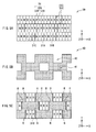
- FIG. 4A is a diagram showing an exemplary configuration in a planar view of the panel section of FIG. 1 according to Modification Example 1
- FIG. 4B is a diagram showing an exemplary configuration in a planar view of the barrier section of FIG. 1 according to Modification Example 1
- FIG. 4C is a diagram showing an exemplary combined configuration of the panel section of FIG. 4A and the barrier section of FIG. 4B in a planar view.
- FIG. 5A is a diagram showing an exemplary configuration in a planar view of the panel section of FIG. 1 according to Modification Example 2
- FIG. 5B is a diagram showing an exemplary configuration in a planar view of the barrier section of FIG. 1 according to Modification Example 2
- FIG. 5C is a diagram showing an exemplary combined configuration of the panel section of FIG. 5A and the barrier section of FIG. 5B in a planar view;
- FIG. 6A is a diagram showing an exemplary configuration in a planar view of the panel section of FIG. 1 according to Modification Example 3
- FIG. 6B is a diagram showing an exemplary configuration in a planar view of the barrier section of FIG. 1 according to Modification Example 3
- FIG. 6C is a diagram showing an exemplary combined configuration of the panel section of FIG. 6A and the barrier section of FIG. 6B in a planar view;
- FIG. 7 is a perspective view of an exemplary electronic unit according to an application example.
- FIG. 1 is a diagram showing an exemplary cross-sectional configuration of a display device 1 according to an embodiment of the present disclosure. Note that FIG. 1 is a schematic view, and the dimension and shape thereof are not necessarily the same as those in reality.
- the display device 1 includes a display panel 20, a backlight 10, and a drive circuit (not shown).
- the backlight 10 is disposed behind the display panel 20, and the drive circuit drives the display panel 20.
- the backlight 10 is a plane-emitting light source that illuminates the display panel 20 from the rear thereof.
- An upper surface of the display panel 20 serves as an image display surface.
- the display panel 20 includes a panel section 30, and a barrier section 40.
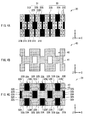
- FIG. 2A is a diagram showing an exemplary configuration in a planar view of the panel section 30 of FIG. 1
- FIG. 2B is a diagram showing an exemplary configuration in a planar view of the barrier section 40 of FIG. 1
- FIG. 2C is a diagram showing an exemplary combined configuration of the panel section 30 of FIG 2A and the barrier section 40 of FIG. 2B in a planar view.
- the panel section 30 is a transmissive panel in which each pixel 31 is driven according to an image signal coming from the outside.
- the panel section 30 is exemplified by a liquid crystal panel, an organic EL (Electro-Luminescence) panel, or a plasma panel. Note that when the panel section 30 has a self-emitting mechanism such as an organic EL panel or a plasma panel, the backlight 10 is not necessarily provided.
- the panel section 30 is in the shape of a square having four sides as shown in FIG. 2A , for example. In the below, as for the four sides of the panel section 30, the two opposing sides are assumed as being parallel to the horizontal direction, and the remaining two sides are assumed as being parallel to the perpendicular direction. Also in the below, the horizontal direction may be referred to as lateral direction or row direction, and the perpendicular direction may be referred to as vertical direction or column direction.
- the panel section 30 includes a display region and ring-shaped frame regions.
- the display region includes a plurality of pixels 31 that are arranged two-dimensionally, and the frame regions are each located on the periphery of the corresponding pixel.
- the pixels 31 in the display region are each configured by a sub-pixel 32R for red, a sub-pixel 32G for green, and a sub-pixel 32B for blue as shown in FIG. 2A , for example. In the below, these sub-pixels 32R, 32G, and 32B are collectively referred to as sub-pixels 32.
- the pixels 31 are not arranged in stripes but differently.
- the pixels 31 are arranged alternately (in a staggered manner) in the column direction and in line in the row direction.
- the sub-pixels 32 are laid out differently on a row basis.
- the pixels 31 in a row each include the sub-pixels arranged in order of R, G, and B
- the pixels 31 in another row each include the sub-pixels arranged in order of B, R, and G
- the pixels 31 in still another row each include the sub-pixels arranged in order of G, B, and R.
- the panel section 30 includes a black section 33 being a light-blocking section between the pixels 31 and between the sub-pixels 32.
- the black section 33 is located around each of the pixels 31, and includes light-blocking sections 33A and 33B.
- the area of the light-blocking section 33A is of the pixel level (the area is equal to or substantially equal to that of the pixel 31, for example), and the area of the light-blocking section 33B is smaller than that of the light-blocking section 33A.
- the light-blocking sections 33A and 33B are arranged alternately in the two-dimensional plane.
- the light-blocking sections 33A and 33B are alternately arranged in the lateral direction (the row direction) with one pixel 31 sandwiched therebetween, and in the vertical direction (the column direction), are alternately arranged with no pixel 31 sandwiched therebetween.
- the black section 33 also includes a light-blocking section 33C between the sub-pixels 32 in the pixel 31.
- the area of the light-blocking section 33C is smaller than that of the light-blocking section 33B.
- the black section 33 includes such a light-blocking section 33C also between the pixels 31 positioned in the vertical direction (the column direction) with respect to each other.
- the barrier section 40 is for blocking a part of the light (image light) coming from each of the pixels 31 of the panel section 30. With the barrier section 40 partially blocking the image light as such, a viewer is allowed to view 2D image (planar image) differently depending on from which appropriate-viewing direction the viewer views (the direction d1 or d2 that will be described later). In this sense, the display device 1 operates as a so-called dual-view display device.
- the barrier section 40 is disposed at the position facing the panel section 30.
- the barrier section 40 is in such a barrier pattern as exemplarily shown in FIG. 2B , that is, a barrier pattern in which a plurality of transmissive regions 42 are arranged two-dimensionally, and a light-blocking region 41 is arranged to be around each of the transmissive regions 42.
- the light-blocking region 41 is configured by a light-blocking member, for example.
- the transmissive regions 42 are each an aperture, for example.
- the transmissive regions 42 are arranged systematically in their entirety, and are arranged two-dimensionally in the row and column directions. As shown in FIG. 2B , for example, the transmissive regions 42 are so arranged as to be displaced by a half pitch on a row basis, and thus the light-blocking region 41 and the transmissive regions 42 are arranged roughly in a checkered pattern (in other words, alternately in the row and column directions), for example.
- the transmissive region 42 As shown in FIG. 2B , for example, the area thereof is of the pixel level (the area is equal to or substantially equal to that of the pixel 31, for example), and the shape and size thereof are the same or almost the same as those of the pixel 31. As shown in FIG. 2B , for example, the transmissive regions 42 are arranged with a pitch of about three pixels in the row direction, and with a pitch of about two pixels in the column direction. In other words, any two transmissive regions 42 adjacent to each other in the row direction have a gap of about two pixels therebetween, and any two transmissive regions 42 adjacent to each other in the column direction have a gap of about one pixel therebetween.
- the transmissive regions 42 are each disposed at the position matching the corresponding light-blocking section 33A, and as exemplarily shown in FIG. 2C , are each disposed at the position opposing to the corresponding light-blocking section 33A.
- the light-blocking region 41 is disposed at the position matching the pixels 31 and the light-blocking sections 33B and 33C, and as exemplarily shown in FIG. 2C , is disposed at the position opposing to the pixels 31 and the light-blocking sections 33B and 33C.
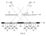
- FIG. 3 is a diagram schematically showing the dual-view display in the display device 1.
- the barrier section 40 is so disposed as to make visible any predetermined pixel 31 via the corresponding transmissive region 42 when a viewer H views the display panel 20 from the first appropriate-viewing direction d1.
- the transmissive regions 42 are each so configured as to allow entire viewing of any one pixel from one transmissive region 42 when the viewer H views the display panel 20 from the first appropriate-viewing direction d1.
- the pixel 31 visible from the corresponding transmissive region 42 as such is referred to as a first pixel 31A.
- the barrier section 40 is so disposed as to make visible any of the pixels 31 other than the first pixel 31A via the corresponding transmissive region 42 when the viewer H views the display panel 20 from the second appropriate-viewing direction d2.
- the transmissive regions 42 are each so configured as to allow entire viewing of any one pixel from one transmissive region 42 when the viewer H views the display panel 20 from the second appropriate-viewing direction d2.
- the pixel 31 visible from the corresponding transmissive region 42 as such is referred to as a second pixel 31 B.
- the first and second pixels 31A and 31B are alternately arranged in the lateral direction, and are alternately arranged also in the vertical direction.
- the first pixel 31A is located adjacent to the right of the light-blocking section 33A, and the second pixel 31 B is located adjacent to the left thereof.
- the first pixel 31A is located adjacent to the left of the light-blocking section 33B, and the second pixel 31B is located adjacent to the right thereof.
- the sub-pixels 32 are laid out differently. Further, also in the two first pixels 31A adjacent to each other in the diagonal direction (in FIG. 2A , in the first pixel 31A in the first row and the first pixel 31A in the second row, for example), the sub-pixels 32 are laid out differently. Still further, in the two second pixels 31B adjacent to each other in the vertical direction (in FIG. 2A , in the second pixel 31 B in the first row and the second pixel 31 B in the third row, for example), the sub-pixels 32 are laid out differently.
- the sub-pixels 32 are laid out differently.
- the transmissive regions 42 are each disposed at the position opposing to the corresponding light-blocking section 33A, the light-blocking sections 33A are visible via the transmissive regions 42 when the viewer H views the display panel 20 from the front.
- transmissive region 42a when the viewer H views the display panel 20 from the front, he or she sees not only the light-blocking section 33A but also a part of the sub-pixels 32R and 32G from the sides thereof.
- the transmissive region 42a is arranged to correspond to the pixel row in which the pixels 31 each include the sub-pixels arranged in order of G, B, and R in the row direction.
- transmissive region 42b when the viewer H views the display panel 20 from the front, he or she sees not only the light-blocking section 33A but also a part of the sub-pixels 32R and 32B from the sides thereof.
- the transmissive region 42b is arranged to correspond to the pixel row in which the pixels 31 each include the sub-pixels arranged in order of R, G, and B in the row direction.
- transmissive region 42c when the viewer H views the display panel 20 from the front, he or she sees not only the light-blocking section 33A but also a part of the sub-pixels 32B and 32G from the sides thereof.
- the transmissive region 42c is arranged to correspond to the pixel row in which the pixels 31 each include the sub-pixels arranged in order of B, R, and G in the row direction.
- the color appearing in the transmissive regions 42a, 42b, and 42c is different from the color disappearing therefrom. There thus is no possibility of causing color moiré when the viewing direction of the viewer H is changed from the first appropriate-viewing direction d1 to the second appropriate-viewing direction d2 with respect to the front, for example.
- the light coming from the backlight 10 is modulated by each of the pixels 31 of the panel section 30, and then any predetermined image light is provided to the barrier section 40. Thereafter, the image light is partially blocked by the light-blocking region 41 of the barrier section 40, and the remaining light passed through the transmissive regions 42 is emitted from the image display surface of the display panel 20.
- the light emitted from the image display surface forms an image at a predetermined position (perspective) on the line segment parallel to the first appropriate-viewing direction d1, thereby generating 2D image (planar image).
- the light emitted from the image display surface forms an image at a predetermined position (perspective) on the line segment parallel to the second appropriate-viewing direction d2, thereby generating 2D image (planar image), for example.
- the transmissive regions 42 of the barrier section 40 are each configured to make entirely visible any one pixel therethrough when viewed from the first or second appropriate-viewing direction d1 or d2. This means that the sub-pixels visible in the transmissive region 42 belong to the same pixel. Moreover, the pixels 31 are arranged not in stripes but differently. Therefore, the color moiré is reduced without displacing the transmissive regions 42 not to match the pixel arrangement. As such, in the embodiment, degradation of the image quality at the time of multi-view display is allowed to be suppressed.
- the sub-pixels 32 are laid out differently, and in the two first pixels 31A adjacent to each other in the diagonal direction, the sub-pixels 32 are also laid out differently. Moreover, in the two second pixels 31B adjacent to each other in the vertical direction, the sub-pixels 32 are laid out differently, and in the two second pixels 31B adjacent to each other in the diagonal direction, the sub-pixels 32 are also laid out differently. Therefore, the color moiré is reduced without displacing the transmissive regions 42 not to match the pixel arrangement.
- the light-blocking sections 33A and 33B are alternately arranged in the row direction with one pixel 31 sandwiched therebetween, and in the column direction, are alternately arranged with no pixel 31 sandwiched therebetween.
- the transmissive regions 42 are each provided at the position matching the corresponding light-blocking section 33A, and the light-blocking region 41 and the transmissive regions 42 are arranged roughly in a checkered pattern (in other words, alternately in the row and column directions). Therefore, the color moiré is reduced even if the transmissive regions 42 are provided at positions matching the pixel arrangement.
- the transmissive regions 42 are each provided in the region opposing to the corresponding light-blocking section 33A, the viewer H may not see any unnecessary image when he or she views the display panel 20 from the front.
- the pixels 31 each include one each of the three sub-pixels 32R, 32G, and 32B of R, G, and B that are arranged in the row direction.
- the color type and the number of the sub-pixels 32 in each of the pixels 31 are not restricted to those described above.
- the arrangement of the sub-pixels 32R, 32G, and 32B in each of the pixels 31 is not also restricted to that described above.
- the pixels 31 may be each configured by one sub-pixel 32R, two sub-pixels 32G, and one sub-pixel 32B.
- the pixels 31 are not arranged in stripes but differently.
- the pixels 31 are arranged alternately (in a staggered manner) in the column direction and in line in the row direction.
- the pixels 31 are each configured by the four sub-pixels 32, and these four sub-pixels 32 are in the 2-by-2 layout.
- the sub-pixels 32 are laid out differently on a row basis.
- the pixels 31 in a row each include the sub-pixels being in the layout of B and G on the right side and R and G on the left side
- the pixels 31 in another row each include the sub-pixels being in the layout of R and G on the right side and B and G on the left side.
- the black section 33 as a light-blocking section is provided between the pixels 31 or between the sub-pixels 32.
- the black section 33 is located around each of the pixels 31, and includes the light-blocking sections 33A and 33B.
- the area of the light-blocking section 33A is of the pixel level (the area is equal to or substantially equal to that of the pixel 31, for example), and the area of the light-blocking section 33B is smaller than that of the light-blocking section 33A.
- the light-blocking sections 33A and 33B are arranged alternately in the two-dimensional plane. As an exemplary arrangement, the light-blocking sections 33A and 33B are alternately arranged in the lateral direction with one pixel 31 sandwiched therebetween, and in the vertical direction, are alternately arranged with no pixel 31 sandwiched therebetween.
- the black section 33 also includes the light-blocking section 33C between the sub-pixels 32 in the pixel 31.
- the area of the light-blocking section 33C is smaller than that of the light-blocking section 33B.
- the black section 33 includes such a light-blocking section 33C also between the pixels 31 positioned in the vertical direction (the column direction) with respect to each other.
- the barrier section 40 is in such a barrier pattern as exemplarily shown in FIG. 4B , that is, a barrier pattern of including a plurality of transmissive regions 42 that are arranged two-dimensionally, and including a light-blocking region 41 that is arranged to be around each of the transmissive regions 42.
- the transmissive regions 42 are so arranged as to be displaced by a half pitch on a row basis, and thus the light-blocking region 41 and the transmissive regions 42 are arranged roughly in a checkered pattern (in other words, alternately in the row and column directions).
- the transmissive region 42 As shown in FIG. 4B , for example, the area thereof is of the pixel level (the area is equal to or substantially equal to that of the pixel 31, for example), and the shape and size thereof are the same or almost the same as those of the pixel 31. As shown in FIG. 4B , for example, the transmissive regions 42 are arranged with a pitch of about three pixels in the row direction, and with a pitch of about two pixels in the column direction. In other words, any two transmissive regions 42 adjacent to each other in the row direction have a gap of about two pixels therebetween, and any two transmissive regions 42 adjacent to each other in the column direction have a gap of about one pixel therebetween.
- the transmissive regions 42 are each disposed at the position matching the corresponding light-blocking section 33A, and as exemplarily shown in FIG. 4C , are each disposed at the position opposing to the corresponding light-blocking section 33A.
- the light-blocking region 41 is disposed at the position matching the pixels 31 and the light-blocking sections 33B and 33C, and as exemplarily shown in FIG. 4C , is disposed at the position opposing to the pixels 31 and the light-blocking sections 33B and 33C.
- the barrier section 40 is so disposed as to make visible any predetermined pixel 31 (the first pixel 31A) via the corresponding transmissive region 42 when the viewer H views the display panel 20 from the first appropriate-viewing direction d1.
- the transmissive regions 42 are each so configured as to allow entire viewing of any one pixel from one transmissive region 42 when the viewer H views the display panel 20 from the first appropriate-viewing direction d1.
- the barrier section 40 is so disposed as to make visible any of the pixels 31 other than the first pixel 31A (the second pixel 31 B) via the corresponding transmissive region 42 when the viewer H views the display panel 20 from the second appropriate-viewing direction d2.
- the transmissive regions 42 are each so configured as to allow entire viewing of any one pixel from one transmissive region 42 when the viewer H views the display panel 20 from the second appropriate-viewing direction d2.
- the first and second pixels 31A and 31 B are alternately arranged in the lateral direction, and are alternately arranged also in the vertical direction.
- the first pixel 31A is located adjacent to the right of the light-blocking section 33A, and the second pixel 31 B is located adjacent to the left thereof.
- the first pixel 31A is located adjacent to the left of the light-blocking section 33B, and the second pixel 31B is located adjacent to the right thereof.
- the sub-pixels 32 are laid out differently in the two first pixels 31 adjacent to each other in the diagonal direction (in FIG. 4A , in the first pixel 31A in the first row and the first pixel 31A in the second row, for example). Further, in the two second pixels 31B adjacent to each other in the diagonal direction (in FIG. 4A , in the second pixel 31B in the first row and the second pixel 31B in the second row, for example), the sub-pixels 32 are laid out differently.
- the transmissive regions 42 are each disposed at the position opposing to the corresponding light-blocking section 33A, the light-blocking sections 33A are visible via the transmissive regions 42 when the viewer H views the display panel 20 from the front.
- transmissive region 42a when the viewer H views the display panel 20 from the front, he or she sees not only the light-blocking section 33A but also a part of the sub-pixels 32R and 32G on the right side thereof. Moreover, the viewer H also sees a part of the sub-pixels 32G and 32B on the left side of the light-blocking section 33A.
- the transmissive region 42a is arranged to correspond to the pixel row in which the pixels 31 each include the sub-pixels being in the layout of R and G on the right side and G and B on the left side.
- transmissive region 42b when the viewer H views the display panel 20 from the front, he or she sees not only the light-blocking section 33A but also a part of the sub-pixels 32R and 32G on the left side thereof. Moreover, the viewer H also sees a part of the sub-pixels 32G and 32B on the right side of the light-blocking section 33A.
- the transmissive region 42b is arranged to correspond to the pixel row in which the pixels 31 each include the sub-pixels being in the layout of B and G on the right side and R and G on the left side.
- the color appearing in the transmissive regions 42a and 42b is different from the color disappearing therefrom. There thus is no possibility of causing the color moiré when the viewing direction of the viewer H is changed from the first appropriate-viewing direction d1 to the second appropriate-viewing direction d2 with respect to the front, for example.
- the light coming from the backlight 10 is modulated by each of the pixels 31 of the panel section 30, and then any predetermined image light is provided to the barrier section 40. Thereafter, the image light is partially blocked by the light-blocking region 41 of the barrier section 40, and the remaining light passed through the transmissive regions 42 is emitted from the image display surface of the display panel 20.
- the light emitted from the image display surface forms an image at a predetermined position (perspective) on the line segment parallel to the first appropriate-viewing direction d1, thereby generating 2D image (planar image).
- the light emitted from the image display surface forms an image at a predetermined position (perspective) on the line segment parallel to the second appropriate-viewing direction d2, thereby generating 2D image (planar image), for example.
- the transmissive regions 42 of the barrier section 40 are each configured to make entirely visible any one pixel therethrough when viewed from the first or second appropriate-viewing direction d1 or d2. This means that the sub-pixels visible in the transmissive region 42 belong to the same pixel. Moreover, the pixels 31 are arranged not in stripes but differently. Therefore, the color moiré is reduced without displacing the transmissive regions 42 not to match the pixel arrangement. As such, in this modification example, degradation of the image quality at the time of multi-view display is allowed to be suppressed.
- the sub-pixels 32 are laid out differently in the two first pixels 31A adjacent to each other in the diagonal direction. Moreover, in the two second pixels 31B adjacent to each other in the diagonal direction, the sub-pixels 32 are also laid out differently. Therefore, the color moiré is reduced without displacing the transmissive regions 42 not to match the pixel arrangement.
- the light-blocking sections 33A and 33B are alternately arranged in the row direction with one pixel 31 sandwiched therebetween, and in the column direction, are alternately arranged with no pixel 31 sandwiched therebetween.
- the transmissive regions 42 are each provided at the position matching the corresponding light-blocking section 33A, and the light-blocking region 41 and the transmissive regions 42 are arranged roughly in a checkered pattern (in other words, alternately in the row and column directions). Therefore, the color moiré is reduced even if the transmissive regions 42 are provided at positions matching the pixel arrangement.
- the pixels 31 may be disposed at the position where the light-blocking sections 33A are provided in the embodiment described above, and the light-blocking sections 33C may be disposed at the position where the light-blocking sections 33B are provided therein.
- the display region of the panel section 30 includes a plurality of sub-pixels 32, which are arranged two-dimensionally with the light-blocking section 33C each provided therebetween.
- the light-blocking sections 33C are in a mesh-like structure with each width thereof being narrower than that of the sub-pixel 32.
- the viewer H views the display panel 20 from the front, as exemplarily shown in FIG.
- the transmissive regions 42 are each provided at the position matching any of the pixels 31 other than the first and second pixels 31A and 31 B.
- the sub-pixels 32 in each of the pixels 31 are arranged not in stripes but differently. Therefore, the color moiré is reduced without displacing the transmissive regions 42 not to match the pixel arrangement. As such, degradation of the image quality at the time of multi-view display is allowed to be suppressed.
- the sub-pixels 32 are laid out differently, and in the two first pixels 31A adjacent to each other in the diagonal direction, the sub-pixels 32 are also laid out differently.
- the sub-pixels 32 are laid out differently, and in the two second pixels 31B adjacent to each other in the diagonal direction, the sub-pixels 32 are also laid out differently. Therefore, the color moiré is reduced without displacing the transmissive regions 42 not to match the pixel arrangement.
- the pixels 31 may be disposed at the position where the light-blocking sections 33A are provided in Modification Example 1 described above, and the light-blocking sections 33C may be disposed at the position where the light-blocking sections 33B are provided therein.
- the display region of the panel section 30 includes a plurality of sub-pixels 32, which are arranged two-dimensionally with the light-blocking section 33C each provided therebetween.
- the corresponding pixel 31 is visible instead of the light-blocking section 33A.
- the sub-pixels 32 are also laid out differently in the two first pixels 31A adjacent to each other in the diagonal direction. Moreover, in the two second pixels 31B adjacent to each other in the diagonal direction, the sub-pixels 32 are also laid out differently. Therefore, the color moiré is reduced without displacing the transmissive regions 42 not to match the pixel arrangement.
- FIG. 7 is a perspective view of an electronic unit 100 in this application example, showing an exemplary schematic configuration thereof.
- the electronic unit 100 is a mobile phone, and as exemplarily shown in FIG. 7 , is provided with a main body section 111, and a display body section 112.
- the display body section 112 is provided to be open and close with respect to the main body section 111.
- the main body section 111 includes operation buttons 115, and a phone mouthpiece section 116.
- the display body section 112 includes a display device 113, and an earpiece section 117.
- the display device 113 is so configured as to perform various displays related to telephone communications on a display screen 114 thereof.
- the electronic unit 100 includes a control section (not shown) for controlling the operation of the display device 113.
- This control section is provided in the main body section 111 or in the display body section 112 as a part of the control section in charge of controlling the electronic unit 100 in its entirely, or as an individual section separately from the control section.
- the display device 113 is in the configuration same as that of the display device 1 in the embodiment and modification examples described above. This accordingly allows the display device 113 to display thereon image excellent in image quality with less color moiré during multi-view display.
- the light-blocking region 41 is made of a light-blocking member, and the transmissive regions 42 are each an aperture.
- the barrier section 40 may be in the dynamic configuration in which the optical characteristics of the light-blocking region 41 are controllable based on a control signal coming from the outside. If this is the configuration, the drive circuit may drive not only the panel section 30 but also the barrier section 40.
- the mobile phone or others described above are surely not restrictive, and examples also include a personal computer, a liquid crystal display television, an image tape recorder of a view finder type or of a monitor direct view type, a car navigation device, a pager, an electronic notepad, a calculator, a word processor, a workstation, a picturephone, a POS (Point-Of-Sale) terminal, and others.
- a personal computer a liquid crystal display television, an image tape recorder of a view finder type or of a monitor direct view type, a car navigation device, a pager, an electronic notepad, a calculator, a word processor, a workstation, a picturephone, a POS (Point-Of-Sale) terminal, and others.
- the present disclosure is also possibly in the following configurations.
Landscapes
- Engineering & Computer Science (AREA)
- Physics & Mathematics (AREA)
- Multimedia (AREA)
- Signal Processing (AREA)
- General Physics & Mathematics (AREA)
- Optics & Photonics (AREA)
- Computer Hardware Design (AREA)
- Theoretical Computer Science (AREA)
- Devices For Indicating Variable Information By Combining Individual Elements (AREA)
- Liquid Crystal (AREA)
Abstract
Description
- The present disclosure relates to a display panel, display device, and electronic unit.
- A display device capable of multi-view display or three-dimensional (3D) display has been recently in practical use. Such a display device is known to include a barrier layer on a display region of a display panel, for example. As an exemplary barrier layer, Japanese Unexamined Patent Application Publication No.
9-281440 8-106070 - The issue here is that, for the provision of such a barrier layer, the slits thereof are sometimes reduced in width to be equal to that of a sub-pixel. If this is the case, however, the distance between the pixels and the barrier layer is reduced, and this results in a smaller processing margin at the time of processing a CF (Color Filter) substrate of a display panel until the thickness thereof becomes suitable for the distance.
In consideration thereof, a possibility is to increase the slit width to be equal to the width of two or more sub-pixels. If the width is increased as such, however, a phenomenon of color moiré may occur when the display panel is viewed from a direction that is not an appropriate-viewing direction. The "color moiré" is a phenomenon observed when the direction of viewing the display panel is changed by degrees in the horizontal plane, and is caused by the resulting similarity of color appearing in the slits and color disappearing therefrom, whereby this looks like glare. - As a measure for the disadvantage described above, a possibility is to change the position of the slits. However, if such a position change causes the sub-pixels visible from each slit to belong to different pixels, the resulting image looks slightly different from the original image. With the measure described above, there thus has been a disadvantage of degradation of the image quality.
- It is thus desirable to provide a display panel capable of suppressing degradation of the image quality at the time of multi-view display, and a display device provided with the display panel, and an electronic unit provided with the display device. Examples of the disclosure can provide multi-view display allowing viewing of two-dimensional (2D) image (planar image) that looks different depending on from which perspective the image is viewed. The present technology relates also to a display device provided with a display panel, and an electronic unit provided with the display device described above. Aspects and features of the invention are defined in the appended claims.
- According to an embodiment of the present disclosure, there is provided a display panel including: a panel section including a display region where a plurality of pixels are arranged, and a gap region provided in a gap between the pixels; and a barrier section including a plurality of transmissive regions in a two-dimensional arrangement, and a light-blocking region to be around each of the transmissive regions. The transmissive regions are each configured to make entirely visible any one of the pixels therethrough when a viewer views the panel section not from a front but from a first or second direction via the barrier section, the pixels are each configured by a plurality of sub-pixels varying in type, and the sub-pixels in each of the pixels are arranged not in stripes but differently.
- According to another embodiment of the present disclosure, there is provided a display device including: a panel section including a display region where a plurality of pixels are arranged, and a gap region provided in a gap between the pixels; a barrier section including a plurality of transmissive regions in a two-dimensional arrangement, and a light-blocking region to be around each of the transmissive regions; and a drive section driving the panel section or both the panel section and the barrier section. The transmissive regions are each of a size allowing viewing of any one of the pixels entirely therethrough when a viewer views the panel section not from a front but from a first or second direction via the barrier section, the pixels are each configured by a plurality of sub-pixels varying in type, and the sub-pixels in each of the pixels are arranged not in stripes but differently.
- According to still another embodiment of the present disclosure, there is provided an electronic unit with a display device, the display device including: a panel section including a display region where a plurality of pixels are arranged, and a gap region provided in a gap between the pixels; a barrier section including a plurality of transmissive regions in a two-dimensional arrangement, and a light-blocking region to be around each of the transmissive regions; and a drive section driving the panel section or both the panel section and the barrier section. The transmissive regions are each configured to make entirely visible any one of the pixels therethrough when a viewer views the panel section not from a front but from a first or second direction via the barrier section, the pixels are each configured by a plurality of sub-pixels varying in type, and the sub-pixels in each of the pixels are arranged not in stripes but differently.
- With the display panel, the display device, and the electronic unit according to the embodiments of the present disclosure, the transmissive regions of the barrier section are each configured to make entirely visible any one pixel therethrough when viewed from the first or second direction. Therefore, the sub-pixels visible in the transmissive region belong to the same pixel. Moreover, the sub-pixels in each of the pixels are arranged not in stripes but differently. Therefore, the color moiré is reduced without displacing the transmissive regions not to match the pixel arrangement.
- With the display panel, the display device, and the electronic unit according to the embodiments of the present disclosure, the pixels include a plurality of first pixels that are each visible through the corresponding transmissive region when viewed from the first direction, and a plurality of second pixels that are each visible through the corresponding transmissive region when viewed from the second direction. In this configuration, in two of the first pixels adjacent to each other in the vertical or diagonal direction, the sub-pixels are preferably laid out differently. Moreover, in two of the second pixels adjacent to each other in the vertical or diagonal direction, the sub-pixels are preferably laid out differently. Therefore, the color moiré is reduced without displacing the transmissive regions not to match the pixel arrangement.
- With the display panel, the display device, and the electronic unit according to the embodiments of the present disclosure, the light-blocking section is configured to include a first light-blocking section whose area is of the pixel level, and a second light-blocking section whose area is smaller than that of the first light-blocking section. In this configuration, preferably, the first and second light-blocking sections are arranged alternately in a two-dimensional plane. Moreover, the first and second light-blocking sections are preferably arranged alternately in the lateral direction with one of the pixels sandwiched therebetween. When the first and second light-blocking sections are arranged at such positions, the transmissive regions are preferably each provided at a position matching the corresponding first light-blocking section.
- With the display panel, the display device, and the electronic unit according to the embodiments of the present disclosure, the sub-pixels visible in any of the slits belong to the same pixel when viewed from the first or second direction, and the color moiré is reduced without displacing the transmissive regions not to match the pixel arrangement. Therefore, degradation of the image quality at the time of multi-view display is allowed to be suppressed.
- It is to be understood that both the foregoing general description and the following detailed description are exemplary, and are intended to provide further explanation of the technology as claimed.
- The accompanying drawings are included to provide a further understanding of the disclosure, and are incorporated in and constitute a part of this specification. The drawings illustrate embodiments and, together with the specification, serve to explain the principles of the technology.
Embodiments of the disclosure will now be described with reference to the accompanying drawings, throughout which like parts are referred to by like references, and in which: -
FIG. 1 is a diagram showing an exemplary cross-sectional configuration of a display device according to an embodiment of the present disclosure; -
FIG. 2A is a diagram showing an exemplary configuration in a planar view of a panel section ofFIG. 1 ,FIG. 2B is a diagram showing an exemplary configuration in a planar view of a barrier section ofFIG. 1 , andFIG. 2C is a diagram showing an exemplary combined configuration of the panel section ofFIG. 2A and the barrier section ofFIG. 2B in a planar view; -
FIG 3 is a schematic diagram for illustrating dual-view display in the display device ofFIG. 1 ; -
FIG. 4A is a diagram showing an exemplary configuration in a planar view of the panel section ofFIG. 1 according to Modification Example 1,FIG. 4B is a diagram showing an exemplary configuration in a planar view of the barrier section ofFIG. 1 according to Modification Example 1, andFIG. 4C is a diagram showing an exemplary combined configuration of the panel section ofFIG. 4A and the barrier section ofFIG. 4B in a planar view. -
FIG. 5A is a diagram showing an exemplary configuration in a planar view of the panel section ofFIG. 1 according to Modification Example 2,FIG. 5B is a diagram showing an exemplary configuration in a planar view of the barrier section ofFIG. 1 according to Modification Example 2, andFIG. 5C is a diagram showing an exemplary combined configuration of the panel section ofFIG. 5A and the barrier section ofFIG. 5B in a planar view; -
FIG. 6A is a diagram showing an exemplary configuration in a planar view of the panel section ofFIG. 1 according to Modification Example 3,FIG. 6B is a diagram showing an exemplary configuration in a planar view of the barrier section ofFIG. 1 according to Modification Example 3, andFIG. 6C is a diagram showing an exemplary combined configuration of the panel section ofFIG. 6A and the barrier section ofFIG. 6B in a planar view; and -
FIG. 7 is a perspective view of an exemplary electronic unit according to an application example. - In the below, an embodiment of the present disclosure is described in detail by referring to the accompanying drawings. Herein, a description is given in the following order.
- 1. Embodiment (
FIGs. 1 to 3 )
Example in which each pixel is configured by RGB, and a wide black section is provided - 2. Modification Examples (
FIGs. 4A to 6C )
Example in which each pixel is configured by RGGB, and a wide black section is provided
Example in which each pixel is configured by RGB, and a general black section is provided
Example in which each pixel is configured by RGGB, and is with a general black section - 3. Application Example (
FIG. 7 )
Example in which a display device of Embodiment and Modification Examples described above is applied to an electronic unit -
FIG. 1 is a diagram showing an exemplary cross-sectional configuration of adisplay device 1 according to an embodiment of the present disclosure. Note thatFIG. 1 is a schematic view, and the dimension and shape thereof are not necessarily the same as those in reality. Thedisplay device 1 includes adisplay panel 20, abacklight 10, and a drive circuit (not shown). Thebacklight 10 is disposed behind thedisplay panel 20, and the drive circuit drives thedisplay panel 20. Thebacklight 10 is a plane-emitting light source that illuminates thedisplay panel 20 from the rear thereof. An upper surface of thedisplay panel 20 serves as an image display surface. Thedisplay panel 20 includes apanel section 30, and abarrier section 40. -
FIG. 2A is a diagram showing an exemplary configuration in a planar view of thepanel section 30 ofFIG. 1 ,FIG. 2B is a diagram showing an exemplary configuration in a planar view of thebarrier section 40 ofFIG. 1 , andFIG. 2C is a diagram showing an exemplary combined configuration of thepanel section 30 ofFIG 2A and thebarrier section 40 ofFIG. 2B in a planar view. - The
panel section 30 is a transmissive panel in which eachpixel 31 is driven according to an image signal coming from the outside. Thepanel section 30 is exemplified by a liquid crystal panel, an organic EL (Electro-Luminescence) panel, or a plasma panel. Note that when thepanel section 30 has a self-emitting mechanism such as an organic EL panel or a plasma panel, thebacklight 10 is not necessarily provided. Thepanel section 30 is in the shape of a square having four sides as shown inFIG. 2A , for example. In the below, as for the four sides of thepanel section 30, the two opposing sides are assumed as being parallel to the horizontal direction, and the remaining two sides are assumed as being parallel to the perpendicular direction. Also in the below, the horizontal direction may be referred to as lateral direction or row direction, and the perpendicular direction may be referred to as vertical direction or column direction. - The
panel section 30 includes a display region and ring-shaped frame regions. The display region includes a plurality ofpixels 31 that are arranged two-dimensionally, and the frame regions are each located on the periphery of the corresponding pixel. Thepixels 31 in the display region are each configured by a sub-pixel 32R for red, a sub-pixel 32G for green, and a sub-pixel 32B for blue as shown inFIG. 2A , for example. In the below, these sub-pixels 32R, 32G, and 32B are collectively referred to as sub-pixels 32. - The
pixels 31 are not arranged in stripes but differently. In an exemplary arrangement, as shown inFIG. 2A , thepixels 31 are arranged alternately (in a staggered manner) in the column direction and in line in the row direction. In thepixels 31, the sub-pixels 32 are laid out differently on a row basis. As an example, thepixels 31 in a row each include the sub-pixels arranged in order of R, G, and B, thepixels 31 in another row each include the sub-pixels arranged in order of B, R, and G, and thepixels 31 in still another row each include the sub-pixels arranged in order of G, B, and R. - The
panel section 30 includes ablack section 33 being a light-blocking section between thepixels 31 and between the sub-pixels 32. As shown inFIG. 2A , for example, theblack section 33 is located around each of thepixels 31, and includes light-blockingsections section 33A is of the pixel level (the area is equal to or substantially equal to that of thepixel 31, for example), and the area of the light-blockingsection 33B is smaller than that of the light-blockingsection 33A. The light-blockingsections sections pixel 31 sandwiched therebetween, and in the vertical direction (the column direction), are alternately arranged with nopixel 31 sandwiched therebetween. - As shown in
FIG. 2A , for example, theblack section 33 also includes a light-blockingsection 33C between the sub-pixels 32 in thepixel 31. The area of the light-blockingsection 33C is smaller than that of the light-blockingsection 33B. Theblack section 33 includes such a light-blockingsection 33C also between thepixels 31 positioned in the vertical direction (the column direction) with respect to each other. - The
barrier section 40 is for blocking a part of the light (image light) coming from each of thepixels 31 of thepanel section 30. With thebarrier section 40 partially blocking the image light as such, a viewer is allowed to view 2D image (planar image) differently depending on from which appropriate-viewing direction the viewer views (the direction d1 or d2 that will be described later). In this sense, thedisplay device 1 operates as a so-called dual-view display device. - As shown in
FIG. 1 , for example, thebarrier section 40 is disposed at the position facing thepanel section 30. Thebarrier section 40 is in such a barrier pattern as exemplarily shown inFIG. 2B , that is, a barrier pattern in which a plurality oftransmissive regions 42 are arranged two-dimensionally, and a light-blockingregion 41 is arranged to be around each of thetransmissive regions 42. - The light-blocking
region 41 is configured by a light-blocking member, for example. On the other hand, thetransmissive regions 42 are each an aperture, for example. Thetransmissive regions 42 are arranged systematically in their entirety, and are arranged two-dimensionally in the row and column directions. As shown inFIG. 2B , for example, thetransmissive regions 42 are so arranged as to be displaced by a half pitch on a row basis, and thus the light-blockingregion 41 and thetransmissive regions 42 are arranged roughly in a checkered pattern (in other words, alternately in the row and column directions), for example. - As for the
transmissive region 42, as shown inFIG. 2B , for example, the area thereof is of the pixel level (the area is equal to or substantially equal to that of thepixel 31, for example), and the shape and size thereof are the same or almost the same as those of thepixel 31. As shown inFIG. 2B , for example, thetransmissive regions 42 are arranged with a pitch of about three pixels in the row direction, and with a pitch of about two pixels in the column direction. In other words, any twotransmissive regions 42 adjacent to each other in the row direction have a gap of about two pixels therebetween, and any twotransmissive regions 42 adjacent to each other in the column direction have a gap of about one pixel therebetween. - The
transmissive regions 42 are each disposed at the position matching the corresponding light-blockingsection 33A, and as exemplarily shown inFIG. 2C , are each disposed at the position opposing to the corresponding light-blockingsection 33A. On the other hand, the light-blockingregion 41 is disposed at the position matching thepixels 31 and the light-blockingsections FIG. 2C , is disposed at the position opposing to thepixels 31 and the light-blockingsections -
FIG. 3 is a diagram schematically showing the dual-view display in thedisplay device 1. As shown inFIG. 3 , thebarrier section 40 is so disposed as to make visible anypredetermined pixel 31 via the correspondingtransmissive region 42 when a viewer H views thedisplay panel 20 from the first appropriate-viewing direction d1. In other words, thetransmissive regions 42 are each so configured as to allow entire viewing of any one pixel from onetransmissive region 42 when the viewer H views thedisplay panel 20 from the first appropriate-viewing direction d1. Herein, when the viewer H views thedisplay panel 20 from the first appropriate-viewing direction d1, thepixel 31 visible from the correspondingtransmissive region 42 as such is referred to as afirst pixel 31A. - Also as shown in
FIG. 3 , thebarrier section 40 is so disposed as to make visible any of thepixels 31 other than thefirst pixel 31A via the correspondingtransmissive region 42 when the viewer H views thedisplay panel 20 from the second appropriate-viewing direction d2. In other words, thetransmissive regions 42 are each so configured as to allow entire viewing of any one pixel from onetransmissive region 42 when the viewer H views thedisplay panel 20 from the second appropriate-viewing direction d2. Herein, when the viewer H views thedisplay panel 20 from the second appropriate-viewing direction d2, thepixel 31 visible from the correspondingtransmissive region 42 as such is referred to as asecond pixel 31 B. - The first and
second pixels first pixel 31A is located adjacent to the right of the light-blockingsection 33A, and thesecond pixel 31 B is located adjacent to the left thereof. Similarly, thefirst pixel 31A is located adjacent to the left of the light-blockingsection 33B, and thesecond pixel 31B is located adjacent to the right thereof. - Herein, in the two
first pixels 31A adjacent to each other in the vertical direction (inFIG. 2A , in thefirst pixel 31A in the first row and thefirst pixel 31A in the third row, for example), the sub-pixels 32 are laid out differently. Further, also in the twofirst pixels 31A adjacent to each other in the diagonal direction (inFIG. 2A , in thefirst pixel 31A in the first row and thefirst pixel 31A in the second row, for example), the sub-pixels 32 are laid out differently. Still further, in the twosecond pixels 31B adjacent to each other in the vertical direction (inFIG. 2A , in thesecond pixel 31 B in the first row and thesecond pixel 31 B in the third row, for example), the sub-pixels 32 are laid out differently. Still further, also in the twosecond pixels 31B adjacent to each other in the diagonal direction (inFIG. 2A , in thesecond pixel 31B in the first row and thesecond pixel 31B in the second row, for example), the sub-pixels 32 are laid out differently. - As shown in
FIGs. 2C and3 , for example, when thetransmissive regions 42 are each disposed at the position opposing to the corresponding light-blockingsection 33A, the light-blockingsections 33A are visible via thetransmissive regions 42 when the viewer H views thedisplay panel 20 from the front. - In this case, as shown in
FIG. 2C , for example, in a certain transmissive region 42 (referred to as transmissive region 42a (not shown)), when the viewer H views thedisplay panel 20 from the front, he or she sees not only the light-blockingsection 33A but also a part of the sub-pixels 32R and 32G from the sides thereof. The transmissive region 42a is arranged to correspond to the pixel row in which thepixels 31 each include the sub-pixels arranged in order of G, B, and R in the row direction. - Similarly, as shown in
FIG. 2C , for example, in another transmissive region 42 (referred to as transmissive region 42b (not shown)), when the viewer H views thedisplay panel 20 from the front, he or she sees not only the light-blockingsection 33A but also a part of the sub-pixels 32R and 32B from the sides thereof. The transmissive region 42b is arranged to correspond to the pixel row in which thepixels 31 each include the sub-pixels arranged in order of R, G, and B in the row direction. - Moreover, also as shown in
FIG. 2C , for example, in still another transmissive region 42 (referred to as transmissive region 42c (not shown)), when the viewer H views thedisplay panel 20 from the front, he or she sees not only the light-blockingsection 33A but also a part of the sub-pixels 32B and 32G from the sides thereof. The transmissive region 42c is arranged to correspond to the pixel row in which thepixels 31 each include the sub-pixels arranged in order of B, R, and G in the row direction. - When the viewing direction of the viewer H is changed from the first appropriate-viewing direction d1 to the second appropriate-viewing direction d2 with respect to the front, for example, the color appearing in the transmissive regions 42a, 42b, and 42c is different from the color disappearing therefrom. There thus is no possibility of causing color moiré when the viewing direction of the viewer H is changed from the first appropriate-viewing direction d1 to the second appropriate-viewing direction d2 with respect to the front, for example.
- In the embodiment, the light coming from the
backlight 10 is modulated by each of thepixels 31 of thepanel section 30, and then any predetermined image light is provided to thebarrier section 40. Thereafter, the image light is partially blocked by the light-blockingregion 41 of thebarrier section 40, and the remaining light passed through thetransmissive regions 42 is emitted from the image display surface of thedisplay panel 20. The light emitted from the image display surface forms an image at a predetermined position (perspective) on the line segment parallel to the first appropriate-viewing direction d1, thereby generating 2D image (planar image). Also the light emitted from the image display surface forms an image at a predetermined position (perspective) on the line segment parallel to the second appropriate-viewing direction d2, thereby generating 2D image (planar image), for example. - In the embodiment, the
transmissive regions 42 of thebarrier section 40 are each configured to make entirely visible any one pixel therethrough when viewed from the first or second appropriate-viewing direction d1 or d2. This means that the sub-pixels visible in thetransmissive region 42 belong to the same pixel. Moreover, thepixels 31 are arranged not in stripes but differently. Therefore, the color moiré is reduced without displacing thetransmissive regions 42 not to match the pixel arrangement. As such, in the embodiment, degradation of the image quality at the time of multi-view display is allowed to be suppressed. - Also in the embodiment, in the two
first pixels 31A adjacent to each other in the vertical direction, the sub-pixels 32 are laid out differently, and in the twofirst pixels 31A adjacent to each other in the diagonal direction, the sub-pixels 32 are also laid out differently. Moreover, in the twosecond pixels 31B adjacent to each other in the vertical direction, the sub-pixels 32 are laid out differently, and in the twosecond pixels 31B adjacent to each other in the diagonal direction, the sub-pixels 32 are also laid out differently. Therefore, the color moiré is reduced without displacing thetransmissive regions 42 not to match the pixel arrangement. - Also in the embodiment, the light-blocking
sections pixel 31 sandwiched therebetween, and in the column direction, are alternately arranged with nopixel 31 sandwiched therebetween. Moreover, thetransmissive regions 42 are each provided at the position matching the corresponding light-blockingsection 33A, and the light-blockingregion 41 and thetransmissive regions 42 are arranged roughly in a checkered pattern (in other words, alternately in the row and column directions). Therefore, the color moiré is reduced even if thetransmissive regions 42 are provided at positions matching the pixel arrangement. - Also in the embodiment, when the
transmissive regions 42 are each provided in the region opposing to the corresponding light-blockingsection 33A, the viewer H may not see any unnecessary image when he or she views thedisplay panel 20 from the front. - In the embodiment described above, the
pixels 31 each include one each of the three sub-pixels 32R, 32G, and 32B of R, G, and B that are arranged in the row direction. However, the color type and the number of the sub-pixels 32 in each of thepixels 31 are not restricted to those described above. Moreover, the arrangement of the sub-pixels 32R, 32G, and 32B in each of thepixels 31 is not also restricted to that described above. - Alternatively, as shown in
FIG. 4A , thepixels 31 may be each configured by onesub-pixel 32R, two sub-pixels 32G, and onesub-pixel 32B. - In this modification example, the
pixels 31 are not arranged in stripes but differently. In an exemplary arrangement, as shown inFIG. 4A , thepixels 31 are arranged alternately (in a staggered manner) in the column direction and in line in the row direction. Thepixels 31 are each configured by the four sub-pixels 32, and these four sub-pixels 32 are in the 2-by-2 layout. In thepixels 31, the sub-pixels 32 are laid out differently on a row basis. As an example, thepixels 31 in a row each include the sub-pixels being in the layout of B and G on the right side and R and G on the left side, and thepixels 31 in another row each include the sub-pixels being in the layout of R and G on the right side and B and G on the left side. - Between the
pixels 31 or between the sub-pixels 32, theblack section 33 as a light-blocking section is provided. As shown inFIG. 4A , for example, theblack section 33 is located around each of thepixels 31, and includes the light-blockingsections section 33A is of the pixel level (the area is equal to or substantially equal to that of thepixel 31, for example), and the area of the light-blockingsection 33B is smaller than that of the light-blockingsection 33A. The light-blockingsections sections pixel 31 sandwiched therebetween, and in the vertical direction, are alternately arranged with nopixel 31 sandwiched therebetween. - As shown in
FIG. 4A , for example, theblack section 33 also includes the light-blockingsection 33C between the sub-pixels 32 in thepixel 31. The area of the light-blockingsection 33C is smaller than that of the light-blockingsection 33B. Theblack section 33 includes such a light-blockingsection 33C also between thepixels 31 positioned in the vertical direction (the column direction) with respect to each other. - The
barrier section 40 is in such a barrier pattern as exemplarily shown inFIG. 4B , that is, a barrier pattern of including a plurality oftransmissive regions 42 that are arranged two-dimensionally, and including a light-blockingregion 41 that is arranged to be around each of thetransmissive regions 42. - As shown in
FIG. 4B , for example, thetransmissive regions 42 are so arranged as to be displaced by a half pitch on a row basis, and thus the light-blockingregion 41 and thetransmissive regions 42 are arranged roughly in a checkered pattern (in other words, alternately in the row and column directions). - As for the
transmissive region 42, as shown inFIG. 4B , for example, the area thereof is of the pixel level (the area is equal to or substantially equal to that of thepixel 31, for example), and the shape and size thereof are the same or almost the same as those of thepixel 31. As shown inFIG. 4B , for example, thetransmissive regions 42 are arranged with a pitch of about three pixels in the row direction, and with a pitch of about two pixels in the column direction. In other words, any twotransmissive regions 42 adjacent to each other in the row direction have a gap of about two pixels therebetween, and any twotransmissive regions 42 adjacent to each other in the column direction have a gap of about one pixel therebetween. - The
transmissive regions 42 are each disposed at the position matching the corresponding light-blockingsection 33A, and as exemplarily shown inFIG. 4C , are each disposed at the position opposing to the corresponding light-blockingsection 33A. On the other hand, the light-blockingregion 41 is disposed at the position matching thepixels 31 and the light-blockingsections FIG. 4C , is disposed at the position opposing to thepixels 31 and the light-blockingsections - Similarly to the embodiment described above, the
barrier section 40 is so disposed as to make visible any predetermined pixel 31 (thefirst pixel 31A) via the correspondingtransmissive region 42 when the viewer H views thedisplay panel 20 from the first appropriate-viewing direction d1. In other words, thetransmissive regions 42 are each so configured as to allow entire viewing of any one pixel from onetransmissive region 42 when the viewer H views thedisplay panel 20 from the first appropriate-viewing direction d1. - Also similarly to the embodiment described above, the
barrier section 40 is so disposed as to make visible any of thepixels 31 other than thefirst pixel 31A (thesecond pixel 31 B) via the correspondingtransmissive region 42 when the viewer H views thedisplay panel 20 from the second appropriate-viewing direction d2. In other words, thetransmissive regions 42 are each so configured as to allow entire viewing of any one pixel from onetransmissive region 42 when the viewer H views thedisplay panel 20 from the second appropriate-viewing direction d2. - The first and
second pixels first pixel 31A is located adjacent to the right of the light-blockingsection 33A, and thesecond pixel 31 B is located adjacent to the left thereof. Similarly, thefirst pixel 31A is located adjacent to the left of the light-blockingsection 33B, and thesecond pixel 31B is located adjacent to the right thereof. - Herein, in the two
first pixels 31 adjacent to each other in the diagonal direction (inFIG. 4A , in thefirst pixel 31A in the first row and thefirst pixel 31A in the second row, for example), the sub-pixels 32 are laid out differently. Further, in the twosecond pixels 31B adjacent to each other in the diagonal direction (inFIG. 4A , in thesecond pixel 31B in the first row and thesecond pixel 31B in the second row, for example), the sub-pixels 32 are laid out differently. - As shown in
FIG. 4C for example, when thetransmissive regions 42 are each disposed at the position opposing to the corresponding light-blockingsection 33A, the light-blockingsections 33A are visible via thetransmissive regions 42 when the viewer H views thedisplay panel 20 from the front. - In this case, as shown in
FIG. 4C , for example, in a certain transmissive region 42 (referred to as transmissive region 42a (not shown)), when the viewer H views thedisplay panel 20 from the front, he or she sees not only the light-blockingsection 33A but also a part of the sub-pixels 32R and 32G on the right side thereof. Moreover, the viewer H also sees a part of the sub-pixels 32G and 32B on the left side of the light-blockingsection 33A. The transmissive region 42a is arranged to correspond to the pixel row in which thepixels 31 each include the sub-pixels being in the layout of R and G on the right side and G and B on the left side. - Similarly, as shown in
FIG. 4C , for example, in another transmissive region 42 (referred to as transmissive region 42b (not shown)), when the viewer H views thedisplay panel 20 from the front, he or she sees not only the light-blockingsection 33A but also a part of the sub-pixels 32R and 32G on the left side thereof. Moreover, the viewer H also sees a part of the sub-pixels 32G and 32B on the right side of the light-blockingsection 33A. The transmissive region 42b is arranged to correspond to the pixel row in which thepixels 31 each include the sub-pixels being in the layout of B and G on the right side and R and G on the left side. - When the viewing direction of the viewer H is changed from the first appropriate-viewing direction d1 to the second appropriate-viewing direction d2 with respect to the front, for example, the color appearing in the transmissive regions 42a and 42b is different from the color disappearing therefrom. There thus is no possibility of causing the color moiré when the viewing direction of the viewer H is changed from the first appropriate-viewing direction d1 to the second appropriate-viewing direction d2 with respect to the front, for example.
- In this modification example, the light coming from the
backlight 10 is modulated by each of thepixels 31 of thepanel section 30, and then any predetermined image light is provided to thebarrier section 40. Thereafter, the image light is partially blocked by the light-blockingregion 41 of thebarrier section 40, and the remaining light passed through thetransmissive regions 42 is emitted from the image display surface of thedisplay panel 20. The light emitted from the image display surface forms an image at a predetermined position (perspective) on the line segment parallel to the first appropriate-viewing direction d1, thereby generating 2D image (planar image). Also the light emitted from the image display surface forms an image at a predetermined position (perspective) on the line segment parallel to the second appropriate-viewing direction d2, thereby generating 2D image (planar image), for example. - In this modification example, the
transmissive regions 42 of thebarrier section 40 are each configured to make entirely visible any one pixel therethrough when viewed from the first or second appropriate-viewing direction d1 or d2. This means that the sub-pixels visible in thetransmissive region 42 belong to the same pixel. Moreover, thepixels 31 are arranged not in stripes but differently. Therefore, the color moiré is reduced without displacing thetransmissive regions 42 not to match the pixel arrangement. As such, in this modification example, degradation of the image quality at the time of multi-view display is allowed to be suppressed. - Also in the modification example, in the two
first pixels 31A adjacent to each other in the diagonal direction, the sub-pixels 32 are laid out differently. Moreover, in the twosecond pixels 31B adjacent to each other in the diagonal direction, the sub-pixels 32 are also laid out differently. Therefore, the color moiré is reduced without displacing thetransmissive regions 42 not to match the pixel arrangement. - Also in the modification example, the light-blocking
sections pixel 31 sandwiched therebetween, and in the column direction, are alternately arranged with nopixel 31 sandwiched therebetween. Moreover, thetransmissive regions 42 are each provided at the position matching the corresponding light-blockingsection 33A, and the light-blockingregion 41 and thetransmissive regions 42 are arranged roughly in a checkered pattern (in other words, alternately in the row and column directions). Therefore, the color moiré is reduced even if thetransmissive regions 42 are provided at positions matching the pixel arrangement. - As an alternative arrangement, the
pixels 31 may be disposed at the position where the light-blockingsections 33A are provided in the embodiment described above, and the light-blockingsections 33C may be disposed at the position where the light-blockingsections 33B are provided therein. If this is the arrangement, as shown inFIG. 5A , for example, the display region of thepanel section 30 includes a plurality of sub-pixels 32, which are arranged two-dimensionally with the light-blockingsection 33C each provided therebetween. In other words, the light-blockingsections 33C are in a mesh-like structure with each width thereof being narrower than that of the sub-pixel 32. In this case, when the viewer H views thedisplay panel 20 from the front, as exemplarily shown inFIG. 5C , in each of thetransmissive regions 42, the correspondingpixel 31 is visible instead of the light-blockingsection 33A. To be specific, thetransmissive regions 42 are each provided at the position matching any of thepixels 31 other than the first andsecond pixels - However, in this modification example, similarly to the embodiment described above, the sub-pixels 32 in each of the
pixels 31 are arranged not in stripes but differently. Therefore, the color moiré is reduced without displacing thetransmissive regions 42 not to match the pixel arrangement. As such, degradation of the image quality at the time of multi-view display is allowed to be suppressed. - Moreover, in this modification example, in the two
first pixels 31A adjacent to each other in the vertical direction, the sub-pixels 32 are laid out differently, and in the twofirst pixels 31A adjacent to each other in the diagonal direction, the sub-pixels 32 are also laid out differently. Moreover, in the twosecond pixels 31B adjacent to each other in the vertical direction, the sub-pixels 32 are laid out differently, and in the twosecond pixels 31B adjacent to each other in the diagonal direction, the sub-pixels 32 are also laid out differently. Therefore, the color moiré is reduced without displacing thetransmissive regions 42 not to match the pixel arrangement. - As an alternative arrangement, the
pixels 31 may be disposed at the position where the light-blockingsections 33A are provided in Modification Example 1 described above, and the light-blockingsections 33C may be disposed at the position where the light-blockingsections 33B are provided therein. If this is the arrangement, as shown inFIG. 6A , for example, the display region of thepanel section 30 includes a plurality of sub-pixels 32, which are arranged two-dimensionally with the light-blockingsection 33C each provided therebetween. In this case, when the viewer H views thedisplay panel 20 from the front, as exemplarily shown inFIG. 6C , in each of thetransmissive regions 42, the correspondingpixel 31 is visible instead of the light-blockingsection 33A. - However, in this modification example, similarly to Modification Example 1 described above, the sub-pixels 32 in each of the
pixels 31 are arranged not in stripes but differently. Therefore, the color moiré is reduced without displacing thetransmissive regions 42 not to match the pixel arrangement. As such, degradation of the image quality at the time of multi-view display is allowed to be suppressed. - Moreover, in this modification example, in the two
first pixels 31A adjacent to each other in the diagonal direction, the sub-pixels 32 are also laid out differently. Moreover, in the twosecond pixels 31B adjacent to each other in the diagonal direction, the sub-pixels 32 are also laid out differently. Therefore, the color moiré is reduced without displacing thetransmissive regions 42 not to match the pixel arrangement. - Described next is an application example of the
display device 1 in the embodiment and modification examples described above.FIG. 7 is a perspective view of anelectronic unit 100 in this application example, showing an exemplary schematic configuration thereof. Theelectronic unit 100 is a mobile phone, and as exemplarily shown inFIG. 7 , is provided with amain body section 111, and adisplay body section 112. Thedisplay body section 112 is provided to be open and close with respect to themain body section 111. Themain body section 111 includesoperation buttons 115, and aphone mouthpiece section 116. Thedisplay body section 112 includes adisplay device 113, and anearpiece section 117. Thedisplay device 113 is so configured as to perform various displays related to telephone communications on adisplay screen 114 thereof. Theelectronic unit 100 includes a control section (not shown) for controlling the operation of thedisplay device 113. This control section is provided in themain body section 111 or in thedisplay body section 112 as a part of the control section in charge of controlling theelectronic unit 100 in its entirely, or as an individual section separately from the control section. - The
display device 113 is in the configuration same as that of thedisplay device 1 in the embodiment and modification examples described above. This accordingly allows thedisplay device 113 to display thereon image excellent in image quality with less color moiré during multi-view display. - While the present technology has been described in detail by referring to the embodiment, the modification examples, and the application example, the present technology is not restrictive to the embodiment and others described above, and numerous other modification may be possibly devised.
- In the embodiment, and the modification examples and the application example thereof described above, exemplified is the case that the light-blocking
region 41 is made of a light-blocking member, and thetransmissive regions 42 are each an aperture. Alternatively, thebarrier section 40 may be in the dynamic configuration in which the optical characteristics of the light-blockingregion 41 are controllable based on a control signal coming from the outside. If this is the configuration, the drive circuit may drive not only thepanel section 30 but also thebarrier section 40. - Note that, as an electronic unit applicable with the
display device 1 in the embodiment and modification examples thereof described above, the mobile phone or others described above are surely not restrictive, and examples also include a personal computer, a liquid crystal display television, an image tape recorder of a view finder type or of a monitor direct view type, a car navigation device, a pager, an electronic notepad, a calculator, a word processor, a workstation, a picturephone, a POS (Point-Of-Sale) terminal, and others. - The present disclosure is also possibly in the following configurations.
- (1) A display panel, including:
- a panel section including a display region where a plurality of pixels are arranged, and a gap region provided in a gap between the pixels; and
- a barrier section including a plurality of transmissive regions in a two-dimensional arrangement, and a light-blocking region to be around each of the transmissive regions, wherein
- the transmissive regions are each configured to make entirely visible any one of the pixels therethrough when a viewer views the panel section not from a front but from a first or second direction via the barrier section,
- the pixels are each configured by a plurality of sub-pixels varying in type, and
- the sub-pixels in each of the pixels are arranged not in stripes but differently.
- (2) The display panel according to (1), wherein
the pixels include a plurality of first pixels and a plurality of second pixels, the first pixels being visible through the transmissive regions when viewed from the first direction, and the second pixels being visible through the transmissive regions when viewed from the second direction,
in two of the first pixels adjacent to each other in a vertical or diagonal direction, the sub-pixels are laid out differently, and
in two of the second pixels adjacent to each other in the vertical or diagonal direction, the sub-pixels are laid out differently. - (3) The display panel according to (2), wherein
the first and second pixels are arranged alternately in a two-dimensional plane. - (4) The display panel according to any one of (1) to (3), wherein
the light-blocking section includes a first light-blocking section whose area is of a pixel level, and a second light-blocking section whose area is smaller than an area of the first light-blocking section. - (5) The display panel according to (4), wherein
the first and second light-blocking sections are arranged alternately in a two-dimensional plane. - (6) The display panel according to (5), wherein
the first and second light-blocking sections are alternately arranged in a lateral direction with one of the pixels sandwiched therebetween. - (7) The display panel according to (6), wherein
the transmissive regions are each provided at a position corresponding to the first light-blocking section. - (8) The display panel according to any one of (1) to (3), wherein
the light-blocking sections are in a mesh structure with each width thereof being narrower than a width of the sub-pixel. - (9) The display panel according to (8), wherein
the pixels include a plurality of first pixels and a plurality of second pixels, the first pixels being visible through the transmissive regions when viewed from the first direction, and the second pixels being visible through the transmissive regions when viewed from the second direction, and
the transmissive regions are each provided at a position corresponding to any of the pixels other than the first and second pixels. - (10) A display device, including:
- a panel section including a display region where a plurality of pixels are arranged, and a gap region provided in a gap between the pixels;
- a barrier section including a plurality of transmissive regions in a two-dimensional arrangement, and a light-blocking region to be around each of the transmissive regions; and
- a drive section driving the panel section or both the panel section and the barrier section, wherein
- the transmissive regions are each of a size allowing viewing of any one of the pixels entirely therethrough when a viewer views the panel section not from a front but from a first or second direction via the barrier section,
- the pixels are each configured by a plurality of sub-pixels varying in type, and
- the sub-pixels in each of the pixels are arranged not in stripes but differently.
- (11) An electronic unit with a display device, the display device including:
- a panel section including a display region where a plurality of pixels are arranged, and a gap region provided in a gap between the pixels;
- a barrier section including a plurality of transmissive regions in a two-dimensional arrangement, and a light-blocking region to be around each of the transmissive regions; and
- a drive section driving the panel section or both the panel section and the barrier section, wherein
- the transmissive regions are each configured to make entirely visible any one of the pixels therethrough when a viewer views the panel section not from a front but from a first or second direction via the barrier section,
- the pixels are each configured by a plurality of sub-pixels varying in type, and
- the sub-pixels in each of the pixels are arranged not in stripes but differently.
- The present disclosure contains subject matter related to that disclosed in Japanese Priority Patent Application
JP 2011-101412
In so far as the embodiments of the disclosure described above are implemented, at least in part, using software-controlled data processing apparatus, it will be appreciated that a computer program providing such software control and a transmission, storage or other medium by which such a computer program is provided are envisaged as aspects of the present disclosure. - It should be understood by those skilled in the art that various modifications, combinations, sub-combinations and alterations may occur depending on design requirements and other factors insofar as they are within the scope of the appended claims or the equivalents thereof.
Claims (11)
- A display panel, comprising:a panel section including a display region where a plurality of pixels are arranged, and a gap region provided in a gap between the pixels; anda barrier section including a plurality of transmissive regions in a two-dimensional arrangement, and a light-blocking region to be around each of the transmissive regions, whereinthe transmissive regions are each configured to make entirely visible any one of the pixels therethrough when a viewer views the panel section not from a front but from a first or second direction via the barrier section,the pixels are each configured by a plurality of sub-pixels varying in type, andthe sub-pixels in each of the pixels are arranged not in stripes but differently.
- The display panel according to claim 1, wherein
the pixels include a plurality of first pixels and a plurality of second pixels, the first pixels being visible through the transmissive regions when viewed from the first direction, and the second pixels being visible through the transmissive regions when viewed from the second direction,
in two of the first pixels adjacent to each other in a vertical or diagonal direction, the sub-pixels are laid out differently, and
in two of the second pixels adjacent to each other in the vertical or diagonal direction, the sub-pixels are laid out differently. - The display panel according to claim 2, wherein
the first and second pixels are arranged alternately in a two-dimensional plane. - The display panel according to claim 1, wherein
the light-blocking section includes a first light-blocking section whose area is of a pixel level, and a second light-blocking section whose area is smaller than an area of the first light-blocking section. - The display panel according to claim 4, wherein
the first and second light-blocking sections are arranged alternately in a two-dimensional plane. - The display panel according to claim 5, wherein
the first and second light-blocking sections are alternately arranged in a lateral direction with one of the pixels sandwiched therebetween. - The display panel according to claim 6, wherein
the transmissive regions are each provided at a position corresponding to the first light-blocking section. - The display panel according to claim 1, wherein
the light-blocking sections are in a mesh structure with each width thereof being narrower than a width of the sub-pixel. - The display panel according to claim 8, wherein
the pixels include a plurality of first pixels and a plurality of second pixels, the first pixels being visible through the transmissive regions when viewed from the first direction, and the second pixels being visible through the transmissive regions when viewed from the second direction, and
the transmissive regions are each provided at a position corresponding to any of the pixels other than the first and second pixels. - A display device, comprising:a panel section including a display region where a plurality of pixels are arranged, and a gap region provided in a gap between the pixels;a barrier section including a plurality of transmissive regions in a two-dimensional arrangement, and a light-blocking region to be around each of the transmissive regions; anda drive section driving the panel section or both the panel section and the barrier section, whereinthe transmissive regions are each of a size allowing viewing of any one of the pixels entirely therethrough when a viewer views the panel section not from a front but from a first or second direction via the barrier section,the pixels are each configured by a plurality of sub-pixels varying in type, andthe sub-pixels in each of the pixels are arranged not in stripes but differently.
- An electronic unit with a display device, the display device comprising:a panel section including a display region where a plurality of pixels are arranged, and a gap region provided in a gap between the pixels;a barrier section including a plurality of transmissive regions in a two-dimensional arrangement, and a light-blocking region to be around each of the transmissive regions; anda drive section driving the panel section or both the panel section and the barrier section, whereinthe transmissive regions are each configured to make entirely visible any one of the pixels therethrough when a viewer views the panel section not from a front but from a first or second direction via the barrier section,the pixels are each configured by a plurality of sub-pixels varying in type, andthe sub-pixels in each of the pixels are arranged not in stripes but differently.
Applications Claiming Priority (1)
| Application Number | Priority Date | Filing Date | Title |
|---|---|---|---|
| JP2011101412A JP5628088B2 (en) | 2011-04-28 | 2011-04-28 | Display panel, display device and electronic device |
Publications (4)
| Publication Number | Publication Date |
|---|---|
| EP2519012A2 true EP2519012A2 (en) | 2012-10-31 |
| EP2519012A3 EP2519012A3 (en) | 2013-02-06 |
| EP2519012B1 EP2519012B1 (en) | 2015-09-09 |
| EP2519012B8 EP2519012B8 (en) | 2015-11-25 |
Family
ID=46049188
Family Applications (1)
| Application Number | Title | Priority Date | Filing Date |
|---|---|---|---|
| EP12164910.7A Not-in-force EP2519012B8 (en) | 2011-04-28 | 2012-04-20 | Display panel and electronic unit |
Country Status (4)
| Country | Link |
|---|---|
| US (3) | US9106904B2 (en) |
| EP (1) | EP2519012B8 (en) |
| JP (1) | JP5628088B2 (en) |
| CN (1) | CN102760387B (en) |
Families Citing this family (8)
| Publication number | Priority date | Publication date | Assignee | Title |
|---|---|---|---|---|
| CN105027191B (en) * | 2013-09-12 | 2017-11-17 | 深圳云英谷科技有限公司 | Method and apparatus for sub-pixel rendering |
| KR102153605B1 (en) * | 2013-11-27 | 2020-09-09 | 삼성디스플레이 주식회사 | Three dimensional image display device |
| CN104793341B (en) * | 2015-05-12 | 2018-01-12 | 京东方科技集团股份有限公司 | A kind of display drive method and device |
| CN105093550A (en) * | 2015-09-02 | 2015-11-25 | 京东方科技集团股份有限公司 | 3D display device and drive method thereof |
| US10534208B2 (en) * | 2016-02-29 | 2020-01-14 | Japan Display Inc. | Display device comprising a separator having a plurality of first and second electrodes respectively forming first and second unit separators at different pitches from each other |
| CN109785757B (en) * | 2019-03-20 | 2021-04-20 | 合肥鑫晟光电科技有限公司 | Display substrate, display panel and display device |
| CN114512082B (en) * | 2020-11-16 | 2024-04-02 | 深圳市万普拉斯科技有限公司 | Display screen, method of driving display screen and display device |
| WO2024105838A1 (en) * | 2022-11-17 | 2024-05-23 | シャープディスプレイテクノロジー株式会社 | Self-luminous display device |
Citations (3)
| Publication number | Priority date | Publication date | Assignee | Title |
|---|---|---|---|---|
| JPH08106070A (en) | 1994-08-08 | 1996-04-23 | Sanyo Electric Co Ltd | Optical shutter and three-dimensional image display device |
| JPH09281440A (en) | 1996-04-17 | 1997-10-31 | Citizen Watch Co Ltd | Stereoscopic display device |
| JP2011101412A (en) | 2011-01-13 | 2011-05-19 | Fujitsu Ten Ltd | Non-directional antenna |
Family Cites Families (15)
| Publication number | Priority date | Publication date | Assignee | Title |
|---|---|---|---|---|
| KR100878269B1 (en) * | 2002-06-18 | 2009-01-13 | 삼성전자주식회사 | Liquid crystal display with time division color display method, driving method and backlight device |
| JP3852935B2 (en) * | 2003-05-30 | 2006-12-06 | 株式会社東芝 | Stereoscopic image display device |
| GB2405546A (en) * | 2003-08-30 | 2005-03-02 | Sharp Kk | Dual view directional display providing images having different angular extent. |
| US7777764B2 (en) * | 2003-09-11 | 2010-08-17 | Sharp Kabushiki Kaisha | Portable display device |
| JP2005110010A (en) | 2003-09-30 | 2005-04-21 | Toshiba Corp | Stereoscopic image generation method and stereoscopic image display device |
| JP4840962B2 (en) * | 2004-06-29 | 2011-12-21 | シャープ株式会社 | 3D display that can be displayed vertically or horizontally |
| GB2415850A (en) | 2004-06-29 | 2006-01-04 | Sharp Kk | Multiple view directional display operable in two orientations. |
| GB2418315A (en) | 2004-09-21 | 2006-03-22 | Sharp Kk | Multiple view display |
| JP2007017822A (en) * | 2005-07-11 | 2007-01-25 | Sanyo Epson Imaging Devices Corp | Display apparatus |
| JP5552204B2 (en) * | 2006-03-27 | 2014-07-16 | 株式会社ジャパンディスプレイ | Display device |
| JP4255032B2 (en) * | 2007-03-15 | 2009-04-15 | 富士通テン株式会社 | Display device and display method |
| JP5173264B2 (en) * | 2007-05-30 | 2013-04-03 | エルジー ディスプレイ カンパニー リミテッド | Image display device |
| JP4973389B2 (en) * | 2007-08-28 | 2012-07-11 | セイコーエプソン株式会社 | Electro-optical device and electronic apparatus |
| JP2010276817A (en) * | 2009-05-28 | 2010-12-09 | Seiko Epson Corp | Electro-optical device and electronic apparatus |
| JP5332978B2 (en) | 2009-07-07 | 2013-11-06 | ソニー株式会社 | 3D display device |
-
2011
- 2011-04-28 JP JP2011101412A patent/JP5628088B2/en not_active Expired - Fee Related
-
2012
- 2012-04-18 CN CN201210114873.6A patent/CN102760387B/en not_active Expired - Fee Related
- 2012-04-18 US US13/449,497 patent/US9106904B2/en active Active
- 2012-04-20 EP EP12164910.7A patent/EP2519012B8/en not_active Not-in-force
-
2015
- 2015-06-30 US US14/755,637 patent/US9251733B2/en active Active
- 2015-12-09 US US14/963,642 patent/US9485832B2/en active Active
Patent Citations (3)
| Publication number | Priority date | Publication date | Assignee | Title |
|---|---|---|---|---|
| JPH08106070A (en) | 1994-08-08 | 1996-04-23 | Sanyo Electric Co Ltd | Optical shutter and three-dimensional image display device |
| JPH09281440A (en) | 1996-04-17 | 1997-10-31 | Citizen Watch Co Ltd | Stereoscopic display device |
| JP2011101412A (en) | 2011-01-13 | 2011-05-19 | Fujitsu Ten Ltd | Non-directional antenna |
Also Published As
| Publication number | Publication date |
|---|---|
| US20150302791A1 (en) | 2015-10-22 |
| CN102760387A (en) | 2012-10-31 |
| US20120274890A1 (en) | 2012-11-01 |
| EP2519012B1 (en) | 2015-09-09 |
| US9106904B2 (en) | 2015-08-11 |
| US9251733B2 (en) | 2016-02-02 |
| JP2012233990A (en) | 2012-11-29 |
| CN102760387B (en) | 2016-05-11 |
| US9485832B2 (en) | 2016-11-01 |
| JP5628088B2 (en) | 2014-11-19 |
| EP2519012B8 (en) | 2015-11-25 |
| US20160095185A1 (en) | 2016-03-31 |
| EP2519012A3 (en) | 2013-02-06 |
Similar Documents
| Publication | Publication Date | Title |
|---|---|---|
| US9485832B2 (en) | Display panel, display device, and electronic unit | |
| US9122065B2 (en) | Display panel, display and electronic device | |
| US8711478B2 (en) | Stereoscopic display | |
| JP5806156B2 (en) | Display device, electronic device | |
| US20130335538A1 (en) | Multiple viewpoint image display device | |
| US9964671B2 (en) | Display substrate, display panel, and stereoscopic display device | |
| US20120229457A1 (en) | Display device | |
| WO2016123998A1 (en) | Pixel array, display device and display method | |
| WO2016127630A1 (en) | Processing method and device for naked eye 3d displaying, and display device | |
| JP2009053645A (en) | Electronic video equipment | |
| US9338444B2 (en) | Display device | |
| US8873142B2 (en) | Display panel, display device, and electronic apparatus capable of improved stereoscopic display | |
| JP5449238B2 (en) | 3D image display device | |
| CN102595175B (en) | Three-dimensional image display apparatus | |
| US20170336643A1 (en) | Display panel and electronic device | |
| JP7072772B2 (en) | Display devices, electronic devices and programs | |
| JP5825736B2 (en) | Stereoscopic image display device and stereoscopic image display optical element | |
| KR100795414B1 (en) | Two screen display PD device |
Legal Events
| Date | Code | Title | Description |
|---|---|---|---|
| PUAI | Public reference made under article 153(3) epc to a published international application that has entered the european phase |
Free format text: ORIGINAL CODE: 0009012 |
|
| 17P | Request for examination filed |
Effective date: 20120504 |
|
| AK | Designated contracting states |
Kind code of ref document: A2 Designated state(s): AL AT BE BG CH CY CZ DE DK EE ES FI FR GB GR HR HU IE IS IT LI LT LU LV MC MK MT NL NO PL PT RO RS SE SI SK SM TR |
|
| AX | Request for extension of the european patent |
Extension state: BA ME |
|
| PUAL | Search report despatched |
Free format text: ORIGINAL CODE: 0009013 |
|
| AK | Designated contracting states |
Kind code of ref document: A3 Designated state(s): AL AT BE BG CH CY CZ DE DK EE ES FI FR GB GR HR HU IE IS IT LI LT LU LV MC MK MT NL NO PL PT RO RS SE SI SK SM TR |
|
| AX | Request for extension of the european patent |
Extension state: BA ME |
|
| RIC1 | Information provided on ipc code assigned before grant |
Ipc: H04N 13/04 20060101AFI20130102BHEP |
|
| RAP1 | Party data changed (applicant data changed or rights of an application transferred) |
Owner name: JAPAN DISPLAY WEST INC. |
|
| 17Q | First examination report despatched |
Effective date: 20130911 |
|
| GRAP | Despatch of communication of intention to grant a patent |
Free format text: ORIGINAL CODE: EPIDOSNIGR1 |
|
| INTG | Intention to grant announced |
Effective date: 20150427 |
|
| GRAS | Grant fee paid |
Free format text: ORIGINAL CODE: EPIDOSNIGR3 |
|
| GRAA | (expected) grant |
Free format text: ORIGINAL CODE: 0009210 |
|
| AK | Designated contracting states |
Kind code of ref document: B1 Designated state(s): AL AT BE BG CH CY CZ DE DK EE ES FI FR GB GR HR HU IE IS IT LI LT LU LV MC MK MT NL NO PL PT RO RS SE SI SK SM TR |
|
| REG | Reference to a national code |
Ref country code: GB Ref legal event code: FG4D |
|
| REG | Reference to a national code |
Ref country code: AT Ref legal event code: REF Ref document number: 748944 Country of ref document: AT Kind code of ref document: T Effective date: 20150915 Ref country code: CH Ref legal event code: EP |
|
| REG | Reference to a national code |
Ref country code: DE Ref legal event code: R082 Ref document number: 602012010251 Country of ref document: DE Representative=s name: D YOUNG & CO LLP, GB |
|
| REG | Reference to a national code |
Ref country code: IE Ref legal event code: FG4D |
|
| RAP2 | Party data changed (patent owner data changed or rights of a patent transferred) |
Owner name: JAPAN DISPLAY INC. |
|
| REG | Reference to a national code |
Ref country code: DE Ref legal event code: R096 Ref document number: 602012010251 Country of ref document: DE |
|
| REG | Reference to a national code |
Ref country code: NL Ref legal event code: MP Effective date: 20150909 |
|
| PG25 | Lapsed in a contracting state [announced via postgrant information from national office to epo] |
Ref country code: GR Free format text: LAPSE BECAUSE OF FAILURE TO SUBMIT A TRANSLATION OF THE DESCRIPTION OR TO PAY THE FEE WITHIN THE PRESCRIBED TIME-LIMIT Effective date: 20151210 Ref country code: FI Free format text: LAPSE BECAUSE OF FAILURE TO SUBMIT A TRANSLATION OF THE DESCRIPTION OR TO PAY THE FEE WITHIN THE PRESCRIBED TIME-LIMIT Effective date: 20150909 Ref country code: LT Free format text: LAPSE BECAUSE OF FAILURE TO SUBMIT A TRANSLATION OF THE DESCRIPTION OR TO PAY THE FEE WITHIN THE PRESCRIBED TIME-LIMIT Effective date: 20150909 Ref country code: NO Free format text: LAPSE BECAUSE OF FAILURE TO SUBMIT A TRANSLATION OF THE DESCRIPTION OR TO PAY THE FEE WITHIN THE PRESCRIBED TIME-LIMIT Effective date: 20151209 Ref country code: LV Free format text: LAPSE BECAUSE OF FAILURE TO SUBMIT A TRANSLATION OF THE DESCRIPTION OR TO PAY THE FEE WITHIN THE PRESCRIBED TIME-LIMIT Effective date: 20150909 |
|
| REG | Reference to a national code |
Ref country code: LT Ref legal event code: MG4D |
|
| REG | Reference to a national code |
Ref country code: AT Ref legal event code: MK05 Ref document number: 748944 Country of ref document: AT Kind code of ref document: T Effective date: 20150909 |
|
| PG25 | Lapsed in a contracting state [announced via postgrant information from national office to epo] |
Ref country code: SE Free format text: LAPSE BECAUSE OF FAILURE TO SUBMIT A TRANSLATION OF THE DESCRIPTION OR TO PAY THE FEE WITHIN THE PRESCRIBED TIME-LIMIT Effective date: 20150909 Ref country code: RS Free format text: LAPSE BECAUSE OF FAILURE TO SUBMIT A TRANSLATION OF THE DESCRIPTION OR TO PAY THE FEE WITHIN THE PRESCRIBED TIME-LIMIT Effective date: 20150909 Ref country code: ES Free format text: LAPSE BECAUSE OF FAILURE TO SUBMIT A TRANSLATION OF THE DESCRIPTION OR TO PAY THE FEE WITHIN THE PRESCRIBED TIME-LIMIT Effective date: 20150909 Ref country code: HR Free format text: LAPSE BECAUSE OF FAILURE TO SUBMIT A TRANSLATION OF THE DESCRIPTION OR TO PAY THE FEE WITHIN THE PRESCRIBED TIME-LIMIT Effective date: 20150909 |
|
| PG25 | Lapsed in a contracting state [announced via postgrant information from national office to epo] |
Ref country code: NL Free format text: LAPSE BECAUSE OF FAILURE TO SUBMIT A TRANSLATION OF THE DESCRIPTION OR TO PAY THE FEE WITHIN THE PRESCRIBED TIME-LIMIT Effective date: 20150909 |
|
| REG | Reference to a national code |
Ref country code: FR Ref legal event code: PLFP Year of fee payment: 5 |
|
| PG25 | Lapsed in a contracting state [announced via postgrant information from national office to epo] |
Ref country code: IT Free format text: LAPSE BECAUSE OF FAILURE TO SUBMIT A TRANSLATION OF THE DESCRIPTION OR TO PAY THE FEE WITHIN THE PRESCRIBED TIME-LIMIT Effective date: 20150909 Ref country code: SK Free format text: LAPSE BECAUSE OF FAILURE TO SUBMIT A TRANSLATION OF THE DESCRIPTION OR TO PAY THE FEE WITHIN THE PRESCRIBED TIME-LIMIT Effective date: 20150909 Ref country code: CZ Free format text: LAPSE BECAUSE OF FAILURE TO SUBMIT A TRANSLATION OF THE DESCRIPTION OR TO PAY THE FEE WITHIN THE PRESCRIBED TIME-LIMIT Effective date: 20150909 Ref country code: EE Free format text: LAPSE BECAUSE OF FAILURE TO SUBMIT A TRANSLATION OF THE DESCRIPTION OR TO PAY THE FEE WITHIN THE PRESCRIBED TIME-LIMIT Effective date: 20150909 Ref country code: IS Free format text: LAPSE BECAUSE OF FAILURE TO SUBMIT A TRANSLATION OF THE DESCRIPTION OR TO PAY THE FEE WITHIN THE PRESCRIBED TIME-LIMIT Effective date: 20160109 |
|
| PG25 | Lapsed in a contracting state [announced via postgrant information from national office to epo] |
Ref country code: RO Free format text: LAPSE BECAUSE OF FAILURE TO SUBMIT A TRANSLATION OF THE DESCRIPTION OR TO PAY THE FEE WITHIN THE PRESCRIBED TIME-LIMIT Effective date: 20150909 Ref country code: AT Free format text: LAPSE BECAUSE OF FAILURE TO SUBMIT A TRANSLATION OF THE DESCRIPTION OR TO PAY THE FEE WITHIN THE PRESCRIBED TIME-LIMIT Effective date: 20150909 Ref country code: PT Free format text: LAPSE BECAUSE OF FAILURE TO SUBMIT A TRANSLATION OF THE DESCRIPTION OR TO PAY THE FEE WITHIN THE PRESCRIBED TIME-LIMIT Effective date: 20160111 Ref country code: PL Free format text: LAPSE BECAUSE OF FAILURE TO SUBMIT A TRANSLATION OF THE DESCRIPTION OR TO PAY THE FEE WITHIN THE PRESCRIBED TIME-LIMIT Effective date: 20150909 |
|
| REG | Reference to a national code |
Ref country code: DE Ref legal event code: R097 Ref document number: 602012010251 Country of ref document: DE |
|
| PLBE | No opposition filed within time limit |
Free format text: ORIGINAL CODE: 0009261 |
|
| STAA | Information on the status of an ep patent application or granted ep patent |
Free format text: STATUS: NO OPPOSITION FILED WITHIN TIME LIMIT |
|
| 26N | No opposition filed |
Effective date: 20160610 |
|
| PG25 | Lapsed in a contracting state [announced via postgrant information from national office to epo] |
Ref country code: SI Free format text: LAPSE BECAUSE OF FAILURE TO SUBMIT A TRANSLATION OF THE DESCRIPTION OR TO PAY THE FEE WITHIN THE PRESCRIBED TIME-LIMIT Effective date: 20150909 Ref country code: DK Free format text: LAPSE BECAUSE OF FAILURE TO SUBMIT A TRANSLATION OF THE DESCRIPTION OR TO PAY THE FEE WITHIN THE PRESCRIBED TIME-LIMIT Effective date: 20150909 Ref country code: BE Free format text: LAPSE BECAUSE OF NON-PAYMENT OF DUE FEES Effective date: 20160430 |
|
| REG | Reference to a national code |
Ref country code: CH Ref legal event code: PL |
|
| PG25 | Lapsed in a contracting state [announced via postgrant information from national office to epo] |
Ref country code: BE Free format text: LAPSE BECAUSE OF FAILURE TO SUBMIT A TRANSLATION OF THE DESCRIPTION OR TO PAY THE FEE WITHIN THE PRESCRIBED TIME-LIMIT Effective date: 20150909 Ref country code: LU Free format text: LAPSE BECAUSE OF FAILURE TO SUBMIT A TRANSLATION OF THE DESCRIPTION OR TO PAY THE FEE WITHIN THE PRESCRIBED TIME-LIMIT Effective date: 20160420 |
|
| REG | Reference to a national code |
Ref country code: IE Ref legal event code: MM4A |
|
| PG25 | Lapsed in a contracting state [announced via postgrant information from national office to epo] |
Ref country code: LI Free format text: LAPSE BECAUSE OF NON-PAYMENT OF DUE FEES Effective date: 20160430 Ref country code: CH Free format text: LAPSE BECAUSE OF NON-PAYMENT OF DUE FEES Effective date: 20160430 |
|
| REG | Reference to a national code |
Ref country code: FR Ref legal event code: PLFP Year of fee payment: 6 |
|
| PG25 | Lapsed in a contracting state [announced via postgrant information from national office to epo] |
Ref country code: IE Free format text: LAPSE BECAUSE OF NON-PAYMENT OF DUE FEES Effective date: 20160420 |
|
| REG | Reference to a national code |
Ref country code: DE Ref legal event code: R079 Ref document number: 602012010251 Country of ref document: DE Free format text: PREVIOUS MAIN CLASS: H04N0013040000 Ipc: H04N0013300000 |
|
| REG | Reference to a national code |
Ref country code: FR Ref legal event code: PLFP Year of fee payment: 7 |
|
| PG25 | Lapsed in a contracting state [announced via postgrant information from national office to epo] |
Ref country code: SM Free format text: LAPSE BECAUSE OF FAILURE TO SUBMIT A TRANSLATION OF THE DESCRIPTION OR TO PAY THE FEE WITHIN THE PRESCRIBED TIME-LIMIT Effective date: 20150909 Ref country code: CY Free format text: LAPSE BECAUSE OF FAILURE TO SUBMIT A TRANSLATION OF THE DESCRIPTION OR TO PAY THE FEE WITHIN THE PRESCRIBED TIME-LIMIT Effective date: 20150909 Ref country code: HU Free format text: LAPSE BECAUSE OF FAILURE TO SUBMIT A TRANSLATION OF THE DESCRIPTION OR TO PAY THE FEE WITHIN THE PRESCRIBED TIME-LIMIT; INVALID AB INITIO Effective date: 20120420 |
|
| PG25 | Lapsed in a contracting state [announced via postgrant information from national office to epo] |
Ref country code: MT Free format text: LAPSE BECAUSE OF NON-PAYMENT OF DUE FEES Effective date: 20160430 Ref country code: MC Free format text: LAPSE BECAUSE OF FAILURE TO SUBMIT A TRANSLATION OF THE DESCRIPTION OR TO PAY THE FEE WITHIN THE PRESCRIBED TIME-LIMIT Effective date: 20150909 Ref country code: TR Free format text: LAPSE BECAUSE OF FAILURE TO SUBMIT A TRANSLATION OF THE DESCRIPTION OR TO PAY THE FEE WITHIN THE PRESCRIBED TIME-LIMIT Effective date: 20150909 Ref country code: MK Free format text: LAPSE BECAUSE OF FAILURE TO SUBMIT A TRANSLATION OF THE DESCRIPTION OR TO PAY THE FEE WITHIN THE PRESCRIBED TIME-LIMIT Effective date: 20150909 |
|
| PG25 | Lapsed in a contracting state [announced via postgrant information from national office to epo] |
Ref country code: BG Free format text: LAPSE BECAUSE OF FAILURE TO SUBMIT A TRANSLATION OF THE DESCRIPTION OR TO PAY THE FEE WITHIN THE PRESCRIBED TIME-LIMIT Effective date: 20150909 |
|
| PG25 | Lapsed in a contracting state [announced via postgrant information from national office to epo] |
Ref country code: AL Free format text: LAPSE BECAUSE OF FAILURE TO SUBMIT A TRANSLATION OF THE DESCRIPTION OR TO PAY THE FEE WITHIN THE PRESCRIBED TIME-LIMIT Effective date: 20150909 |
|
| PGFP | Annual fee paid to national office [announced via postgrant information from national office to epo] |
Ref country code: FR Payment date: 20190418 Year of fee payment: 8 |
|
| PGFP | Annual fee paid to national office [announced via postgrant information from national office to epo] |
Ref country code: DE Payment date: 20200420 Year of fee payment: 9 |
|
| PGFP | Annual fee paid to national office [announced via postgrant information from national office to epo] |
Ref country code: GB Payment date: 20200427 Year of fee payment: 9 |
|
| REG | Reference to a national code |
Ref country code: DE Ref legal event code: R082 Ref document number: 602012010251 Country of ref document: DE Representative=s name: D YOUNG & CO LLP, DE |
|
| PG25 | Lapsed in a contracting state [announced via postgrant information from national office to epo] |
Ref country code: FR Free format text: LAPSE BECAUSE OF NON-PAYMENT OF DUE FEES Effective date: 20200430 |
|
| REG | Reference to a national code |
Ref country code: DE Ref legal event code: R119 Ref document number: 602012010251 Country of ref document: DE |
|
| GBPC | Gb: european patent ceased through non-payment of renewal fee |
Effective date: 20210420 |
|
| PG25 | Lapsed in a contracting state [announced via postgrant information from national office to epo] |
Ref country code: DE Free format text: LAPSE BECAUSE OF NON-PAYMENT OF DUE FEES Effective date: 20211103 Ref country code: GB Free format text: LAPSE BECAUSE OF NON-PAYMENT OF DUE FEES Effective date: 20210420 |