EP2518752B1 - Fault trip indicator by the position of the handle - Google Patents
Fault trip indicator by the position of the handle Download PDFInfo
- Publication number
- EP2518752B1 EP2518752B1 EP12305477.7A EP12305477A EP2518752B1 EP 2518752 B1 EP2518752 B1 EP 2518752B1 EP 12305477 A EP12305477 A EP 12305477A EP 2518752 B1 EP2518752 B1 EP 2518752B1
- Authority
- EP
- European Patent Office
- Prior art keywords
- lever
- obstacle
- link rod
- protection apparatus
- assembly
- Prior art date
- Legal status (The legal status is an assumption and is not a legal conclusion. Google has not performed a legal analysis and makes no representation as to the accuracy of the status listed.)
- Active
Links
- 230000033001 locomotion Effects 0.000 claims description 6
- 239000000463 material Substances 0.000 claims description 6
- 230000000694 effects Effects 0.000 claims description 3
- 230000011664 signaling Effects 0.000 description 5
- 230000000717 retained effect Effects 0.000 description 3
- 238000013459 approach Methods 0.000 description 2
- 230000007547 defect Effects 0.000 description 2
- 238000000034 method Methods 0.000 description 2
- 238000005452 bending Methods 0.000 description 1
- 230000000903 blocking effect Effects 0.000 description 1
- 238000001514 detection method Methods 0.000 description 1
- 238000006073 displacement reaction Methods 0.000 description 1
- 239000000428 dust Substances 0.000 description 1
- 230000005611 electricity Effects 0.000 description 1
- 230000003100 immobilizing effect Effects 0.000 description 1
- 238000000926 separation method Methods 0.000 description 1
Images

Classifications
-
- H—ELECTRICITY
- H01—ELECTRIC ELEMENTS
- H01H—ELECTRIC SWITCHES; RELAYS; SELECTORS; EMERGENCY PROTECTIVE DEVICES
- H01H71/00—Details of the protective switches or relays covered by groups H01H73/00 - H01H83/00
- H01H71/04—Means for indicating condition of the switching device
-
- H—ELECTRICITY
- H01—ELECTRIC ELEMENTS
- H01H—ELECTRIC SWITCHES; RELAYS; SELECTORS; EMERGENCY PROTECTIVE DEVICES
- H01H71/00—Details of the protective switches or relays covered by groups H01H73/00 - H01H83/00
- H01H71/10—Operating or release mechanisms
- H01H71/50—Manual reset mechanisms which may be also used for manual release
- H01H71/52—Manual reset mechanisms which may be also used for manual release actuated by lever
- H01H71/528—Manual reset mechanisms which may be also used for manual release actuated by lever comprising a toggle or collapsible link between handle and contact arm, e.g. sear pin mechanism
-
- H—ELECTRICITY
- H01—ELECTRIC ELEMENTS
- H01H—ELECTRIC SWITCHES; RELAYS; SELECTORS; EMERGENCY PROTECTIVE DEVICES
- H01H71/00—Details of the protective switches or relays covered by groups H01H73/00 - H01H83/00
- H01H71/04—Means for indicating condition of the switching device
- H01H2071/046—Means for indicating condition of the switching device exclusively by position of operating part, e.g. with additional labels or marks but no other movable indicators
-
- H—ELECTRICITY
- H01—ELECTRIC ELEMENTS
- H01H—ELECTRIC SWITCHES; RELAYS; SELECTORS; EMERGENCY PROTECTIVE DEVICES
- H01H71/00—Details of the protective switches or relays covered by groups H01H73/00 - H01H83/00
- H01H71/10—Operating or release mechanisms
- H01H71/50—Manual reset mechanisms which may be also used for manual release
- H01H71/52—Manual reset mechanisms which may be also used for manual release actuated by lever
- H01H71/526—Manual reset mechanisms which may be also used for manual release actuated by lever the lever forming a toggle linkage with a second lever, the free end of which is directly and releasably engageable with a contact structure
Definitions
- the present invention relates to circuit-breaker-type electrical protection devices, and more particularly relates to an electrical fault signaling device on one of the lines protected by the device, the occurrence of such a defect manifesting itself concretely in a device. particular position of the control lever of said apparatus.
- the purpose is to allow the user to know immediately if the device has been opened manually or if the opening of the contacts results from an incident.
- Such information in addition to its security as it provides information on the exact state of the protected line, may influence the decision-making approach taken by the user before a possible rearming of the product, regardless of his knowledge of electricity .
- this information is given in such a way that it is visible even in dark environments, which is particularly advantageous with regard to the location of the electrical panels in many configurations.
- the object of the invention is to propose a signaling technique that relies very much on the device as it exists, without it is necessary to rethink all or part of the product, but at least modify it at least.
- This type of apparatus comprises at least one pair of respectively fixed and movable contacts, the control lever which has been mentioned to move their relative position between a first position of separation and a second position of contact.
- This lever is in fact connected to the movable contact via a mechanical lock based on a toggle comprising on the one hand a link and on the other hand a pivoting assembly against biasing means.
- This assembly comprises a movable contact carrier and a trigger mounted relative rotation, the trigger cooperating also with at least one actuator adapted to reflect an electrical fault on the line. It is typically a magnetic actuator for the detection of short circuits, and a thermal actuator detecting overloads on the line.
- One end of the link of the toggle is rotatably mounted at the periphery of the handle, while the other end is positioned in abutment on an outgrowth of the contact carrier against which it is held by a spout of the trigger.
- a link balance / trigger / contact carrier is then implemented.
- an action on the said trigger causes it to rotate relative to the contact-holder, and the tilting of the lock under the effect of the return means by breaking the aforementioned equilibrium, rupture causing the release of the end of the rod beyond the protrusion relative to the axis of rotation of the trigger / contact carrier assembly.
- Reminder means linked to the handle then recall the rod and its end released towards the axis of rotation of said lever along a path external to said assembly.
- the action on the handle in the direction of closing or opening the contacts respects the balance rod / trigger / contact holder.
- the end of the link retains the same position relative to the trigger / contact carrier assembly, and makes a path respecting the mentioned balance. This path is the same, but in the opposite direction, that which is performed when there is manual closing of the product.
- the broken balance leading to expel the end of the rod of the trigger / contact assembly the end in question of the rod footprint a different path when the handle returns to its open position.
- the electrical apparatus comprises an obstacle placed on said path, blocking the rod / lever assembly in an intermediate position. signaling the triggering of the lock following an electrical fault on a line, said obstacle being at least partially retractable and / or deformable when the force exerted on the handle is greater than the force resulting from the return means of the joystick.
- This obstacle acts only when the trajectory of the link is changed by breaking the equilibrium, leaving unchanged the operation during the arming operation, that is to say closing the contacts.
- the operation is not further modified during manual opening, said obstacle having no effect when the trajectory of the end of the rod is imposed by its equilibrium state with the contact-holder assembly. trigger.
- the resetting of the product following a fault can only be carried out following an acknowledgment, operated in the following manner: it is necessary to manually operate the handle in the open position of the contacts before the product can be reset.
- the obstacle is at least partially retractable and / or deformable is exploited during this acknowledgment operation, insofar as it implements a greater effort than that which comes from the mainspring, resulting in to move or deform the obstacle during the action on the lever to bring it to the open position of the contacts.
- At least a portion of said obstacle is provided with a flexible material so that the complete rotation of the handle deforms it elastically by means of the released end of the link.
- the obstacle according to the invention comprises a protuberance extending towards the inside of the front of the housing of the apparatus which exceeds the control handle, or extending towards the inside of a wall. orienting substantially parallel to said facade of a flange-type element secured to the housing.
- This solution reflects the position of the lock in the housing of the electrical device concerned by the invention, in the vicinity of said facade.
- the obstacle according to the invention can therefore be integrated either with an existing part, conventionally provided in the environment of the lock, for example of the flange, envelope or other type, but this is not the preferential solution, directly to the case.
- the protrusion may be made of a flexible material, and it deforms when the end of the link is driven by the manual rotation of the handle to open the contacts of the device.
- the wall oriented substantially parallel to the front of a flange-type element secured to the housing can also be provided flexible, at least in the fastening area of the protuberance.
- the obstacle may also include, in addition to the protrusion, the protrusion of the contact carrier with which it cooperates to form a more complex obstacle.
- This possibility arises from the kinematics of the assembly, which is such that if the rod is retained in the intermediate position at the opening of the contacts, the contact carrier is itself on the path of its end, positioned next to the protuberance.
- the acknowledgment operation could then also be implemented by making the protrusion of the contact carrier flexible, and therefore deformable.
- the trigger tip may comprise a recess forming a clearance in a portion likely to interfere with the protrusion constituting the obstacle, during their relative motion.
- the path of the end of the rod released by the movable contact / trigger assembly is indeed very close to the components of said assembly, and it Of course, the obstacle does not interfere with the latter in normal operation.
- the piece shown is a flange (1) with a protuberance (2) forming the obstacle which is the heart of the invention, a piece which is pressed against a portion of the handle and the lock.
- a flange (1) With reference to the figure 1 , the piece shown is a flange (1) with a protuberance (2) forming the obstacle which is the heart of the invention, a piece which is pressed against a portion of the handle and the lock.
- Such lock mainly comprises three elements, a link (3) and a trigger assembly (4) / contact carrier (5) carrying the movable contact (6), the assembly forming a toggle.
- the trigger (4) is visible in figure 2 , having a recess (14) forming clearance for its free movement relative to the obstacle (2) placed on the flange (1).
- the invention does not relate to the operation of the lock itself, it will not be detailed in the following. Only aspects / phases of interest within the meaning of the invention will be explained. Thus, such a clearance (14) is for example not necessary on a trigger of a traditional lock operating without the system of the invention.
- this flange (1) is however necessary for the explanation which corresponds to the figure 4 , in which the reverse manipulation is performed: the handle (8) is controlled so that the contacts (6, 7) are spaced from each other, so as to open the line.
- the path t followed by the end (3b) of the rod (3) is strictly identical to the displacement corresponding to the closure of the contacts as illustrated in FIG. Figures 3a and 3b but in the opposite direction.
- the equilibrium link (3) / trigger (4) / contact carrier (5) is retained, the operation is simply reversed with respect to the arming phase described above.
- the protuberance (2) constituting the obstacle set up according to the invention does not interfere with the path t, the end (3b) of the rod (3) being too low.
- a magnetic or thermal actuator exerts an action on the trigger (4), resulting in the rupture of the equilibrium link (3) / trigger (4) / contact carrier (5).
- the rod (3), and in particular its end (3b) is ejected upwards, as appears in figure 5a .
- the contact carrier return spring (5) recalls the trigger assembly (4) / contact carrier (5) in open contact position (6, 7).
- return means (not visible) attached to the handle (8) tend to recall the entire handle (8) / link (3) in the position contacts (6, 7) open.
- the return means respectively of the contact-holder assembly (5) / trigger (4) and of the handle (8) / rod (3) assembly are provided in such a way that their speed of movement is not the same. even. It is indeed quite fundamental that the contacts (6, 7) deviate at a high speed, whereas the return of the handle (8) / link (3) in open contacts position does not need to be fast. Their return is therefore always after the trigger assembly (4) / contact carrier (5).
- the protuberance (2) is provided in a flexible material, so that the manipulation of the handle (8) in the direction of the arrow F 'is possible by bending said protuberance (2), which deforms and lets the rod pass (3) in the direction of the trigger assembly (4) / contact carrier (5), so that the end (3b) is inserted between the spout (10) and the protrusion (9) to recover its place and reform the initial equilibrium link (3) / trigger (4) / contact carrier (5).
- the figure 5b shows that the end (3b) is actually retained by the protuberance (2) and the protrusion (9), located opposite one another: we could very well consider that the deformation of the obstacle that they together constitute either supported by said protrusion (9), then provided elastically deformable material, or by the protuberance (2) and the protrusion (9) together.
Landscapes
- Switch Cases, Indication, And Locking (AREA)
- Breakers (AREA)
Description
La présente invention concerne les appareils électriques de protection de ligne de type disjoncteur, et a plus particulièrement trait à un dispositif de signalisation de défaut électrique sur une des lignes protégées par l'appareil, la survenue d'un tel défaut se manifestant concrètement par une position particulière de la manette de commande dudit appareil.The present invention relates to circuit-breaker-type electrical protection devices, and more particularly relates to an electrical fault signaling device on one of the lines protected by the device, the occurrence of such a defect manifesting itself concretely in a device. particular position of the control lever of said apparatus.
Un tel appareil est divulgué dans le
Le but est de permettre à l'utilisateur de savoir immédiatement si l'appareil a été ouvert manuellement ou si l'ouverture des contacts résulte d'un incident. Une telle information, outre son caractère sécuritaire puisqu'elle renseigne sur l'état exact de la ligne protégée, peut influer sur l'approche décisionnelle prise par l'utilisateur avant un éventuel réarmement du produit, quelles que soient par ailleurs ses connaissances en électricité. Sur un plan pratique, cette information est donnée de manière telle qu'elle est visible même dans des ambiances sombres, ce qui est particulièrement avantageux au regard de l'emplacement des tableaux électriques dans nombres de configurations.The purpose is to allow the user to know immediately if the device has been opened manually or if the opening of the contacts results from an incident. Such information, in addition to its security as it provides information on the exact state of the protected line, may influence the decision-making approach taken by the user before a possible rearming of the product, regardless of his knowledge of electricity . On a practical level, this information is given in such a way that it is visible even in dark environments, which is particularly advantageous with regard to the location of the electrical panels in many configurations.
Enfin, l'information étant donnée par le positionnement particulier de la manette de commande, laquelle fait évidemment déjà partie de ce type de produit, elle ne nécessite pas la mise en oeuvre de composants particuliers supplémentaires, ni l'élaboration d'une solution à conception et mise au point lourdes. La configuration prônée par l'invention fait de plus partie d'une solution qui n'a pas d'impact sur le processus d'assemblage existant.Finally, the information being given by the particular positioning of the joystick, which is obviously already part of this type of product, it does not require the implementation of additional particular components, or the development of a solution to heavy design and focus. The configuration advocated by the invention is also part of a solution that has no impact on the existing assembly process.
En somme, le but de l'invention est de proposer une technique de signalisation qui repose très largement sur le dispositif tel qu'il existe, sans qu'il soit nécessaire de repenser tout ou partie du produit, mais en le modifiant au contraire a minima.In short, the object of the invention is to propose a signaling technique that relies very much on the device as it exists, without it is necessary to rethink all or part of the product, but at least modify it at least.
Un appareil électrique selon l'invention est défini dans la revendication 1.An electrical apparatus according to the invention is defined in
Ce genre d'appareil comprend au moins une paire de contacts respectivement fixe et mobile, la manette de commande dont il a été fait mention permettant de faire passer leur position relative entre une première position d'écartement et une seconde position de contact. Cette manette est en fait reliée au contact mobile par l'intermédiaire d'une serrure mécanique basée sur une genouillère comportant d'une part une biellette et d'autre part un assemblage pivotant à l'encontre de moyens de rappel. Cet assemblage comprend un porte-contact mobile et un déclencheur montés à rotation relative, le déclencheur coopérant par ailleurs avec au moins un actionneur apte à répercuter un défaut électrique sur la ligne. Il s'agit typiquement d'un actionneur magnétique permettant la détection de courts-circuits, et d'un actionneur thermique détectant les surcharges sur la ligne.This type of apparatus comprises at least one pair of respectively fixed and movable contacts, the control lever which has been mentioned to move their relative position between a first position of separation and a second position of contact. This lever is in fact connected to the movable contact via a mechanical lock based on a toggle comprising on the one hand a link and on the other hand a pivoting assembly against biasing means. This assembly comprises a movable contact carrier and a trigger mounted relative rotation, the trigger cooperating also with at least one actuator adapted to reflect an electrical fault on the line. It is typically a magnetic actuator for the detection of short circuits, and a thermal actuator detecting overloads on the line.
L'une des extrémités de la biellette de la genouillère est montée en rotation en périphérie de la manette, alors que l'autre extrémité se positionne en appui sur une excroissance du porte-contact contre laquelle elle est maintenue par un bec du déclencheur. Un équilibre biellette / déclencheur / porte-contact est alors mis en oeuvre. En cas de défaut sur la ligne, une action sur ledit déclencheur provoque sa rotation par rapport au porte-contact, et le basculement de la serrure sous l'effet des moyens de rappel par rupture de l'équilibre mentionné, rupture provoquant la libération de l'extrémité de la biellette au-delà de l'excroissance par rapport à l'axe de rotation de l'assemblage déclencheur / porte-contact. Des moyens de rappel liés à la manette rappellent ensuite la biellette et son extrémité libérée vers l'axe de rotation de ladite manette selon un trajet externe audit assemblage.One end of the link of the toggle is rotatably mounted at the periphery of the handle, while the other end is positioned in abutment on an outgrowth of the contact carrier against which it is held by a spout of the trigger. A link balance / trigger / contact carrier is then implemented. In the event of a fault on the line, an action on the said trigger causes it to rotate relative to the contact-holder, and the tilting of the lock under the effect of the return means by breaking the aforementioned equilibrium, rupture causing the release of the end of the rod beyond the protrusion relative to the axis of rotation of the trigger / contact carrier assembly. Reminder means linked to the handle then recall the rod and its end released towards the axis of rotation of said lever along a path external to said assembly.
L'action sur la manette dans le sens de la fermeture ou de l'ouverture des contacts respecte l'équilibre bielle / déclencheur / porte-contact. En d'autres termes, lorsque les contacts sont ouverts par action volontaire de l'utilisateur sur la manette, l'extrémité de la biellette conserve le même positionnement par rapport à l'assemblage déclencheur / porte-contact, et effectue un trajet respectant l'équilibre mentionné. Ce trajet est le même, mais en sens inverse, que celui qui est effectué lorsqu'il y a fermeture manuelle du produit. Au contraire, lorsque le produit est ouvert par une action sur le déclencheur, l'équilibre rompu conduisant à expulser l'extrémité de la biellette de l'assemblage déclencheur / porte-contact, l'extrémité en question de la biellette empreinte une trajectoire différente lorsque la manette revient vers sa position d'ouverture.The action on the handle in the direction of closing or opening the contacts respects the balance rod / trigger / contact holder. In other words, when the contacts are opened by deliberate action of the user on the handle, the end of the link retains the same position relative to the trigger / contact carrier assembly, and makes a path respecting the mentioned balance. This path is the same, but in the opposite direction, that which is performed when there is manual closing of the product. On the contrary, when the product is opened by an action on the trigger, the broken balance leading to expel the end of the rod of the trigger / contact assembly, the end in question of the rod footprint a different path when the handle returns to its open position.
C'est la différence de trajet qui est exploitée dans le cadre de l'invention, qui se caractérise à titre principal en ce que l'appareil électrique comporte un obstacle placé sur ledit trajet, bloquant l'ensemble biellette / manette en une position intermédiaire signalant le déclenchement de la serrure suite à un défaut électrique sur une ligne, ledit obstacle étant au moins partiellement escamotable et/ou déformable lorsque l'effort exercé sur la manette est supérieur à l'effort résultant des moyens de rappel de la manette.It is the path difference that is exploited in the context of the invention, which is mainly characterized in that the electrical apparatus comprises an obstacle placed on said path, blocking the rod / lever assembly in an intermediate position. signaling the triggering of the lock following an electrical fault on a line, said obstacle being at least partially retractable and / or deformable when the force exerted on the handle is greater than the force resulting from the return means of the joystick.
Cet obstacle n'agit que lorsque la trajectoire de la biellette est modifiée par rupture de l'équilibre, laissant inchangé le fonctionnement lors de l'opération d'armement, c'est-à-dire de fermeture des contacts. Le fonctionnement n'est pas davantage modifié lors d'une ouverture manuelle, ledit obstacle n'ayant pas d'effet lorsque la trajectoire de l'extrémité de la biellette est imposée par son état d'équilibre avec l'assemblage porte-contact / déclencheur. Le réarmement du produit consécutif à un défaut ne peut s'effectuer que suite à un acquittement, opéré de la manière suivante : il est nécessaire d'actionner manuellement la manette en position d'ouverture des contacts avant de pouvoir réarmer le produit. Le fait que l'obstacle soit au moins partiellement escamotable et/ou déformable est exploité au cours de cette opération d'acquittement, dans la mesure où l'on met en oeuvre un effort supérieur à celui qui provient du ressort de la manette, aboutissant à déplacer ou à déformer l'obstacle lors de l'action sur la manette visant à l'amener en position d'ouverture des contacts.This obstacle acts only when the trajectory of the link is changed by breaking the equilibrium, leaving unchanged the operation during the arming operation, that is to say closing the contacts. The operation is not further modified during manual opening, said obstacle having no effect when the trajectory of the end of the rod is imposed by its equilibrium state with the contact-holder assembly. trigger. The resetting of the product following a fault can only be carried out following an acknowledgment, operated in the following manner: it is necessary to manually operate the handle in the open position of the contacts before the product can be reset. The fact that the obstacle is at least partially retractable and / or deformable is exploited during this acknowledgment operation, insofar as it implements a greater effort than that which comes from the mainspring, resulting in to move or deform the obstacle during the action on the lever to bring it to the open position of the contacts.
Pour les professionnels, le fonctionnement est tout à fait similaire à celui qui caractérise les produits de la famille des boîtiers moulés, en général dévolus aux puissances supérieures, ce qui peut être considéré comme un avantage supplémentaire de l'invention puisque la connaissance de ce type de fonctionnement existe. Il est également à noter que, vu la conception de ce système, fonctionnant de manière totalement interne au produit, ce nouveau moyen d'indication est totalement insensible aux pollutions pouvant résulter de l'existence de poussière, de pollution liée à la coupure, etc.For professionals, the operation is quite similar to that which characterizes the products of the family of molded housings, generally devolving to higher powers, which can be considered as an additional advantage of the invention since the knowledge of this type of operation exists. It should also be noted that, considering the design of this system, operating completely internal to the product, this new means of indication is completely insensitive to pollution that may result from the existence of dust, pollution related to the cut, etc. .
En fait, selon une possibilité, au moins une partie dudit obstacle est prévue en matériau flexible pour que la rotation complète de la manette la déforme élastiquement au moyen de l'extrémité libérée de la biellette.In fact, according to one possibility, at least a portion of said obstacle is provided with a flexible material so that the complete rotation of the handle deforms it elastically by means of the released end of the link.
Plus précisément encore, l'obstacle selon l'invention comporte une protubérance s'étendant vers l'intérieur de la façade du boîtier de l'appareil dont dépasse la manette de commande, ou s'étendant vers l'intérieur d'une paroi s'orientant sensiblement parallèlement à ladite façade d'un élément de type flasque solidarisé au boîtier.More specifically, the obstacle according to the invention comprises a protuberance extending towards the inside of the front of the housing of the apparatus which exceeds the control handle, or extending towards the inside of a wall. orienting substantially parallel to said facade of a flange-type element secured to the housing.
Cette solution reflète la position de la serrure dans le boîtier de l'appareil électrique concerné par l'invention, au voisinage de ladite façade. L'obstacle selon l'invention peut dès lors être intégré soit à une pièce existante, prévue classiquement dans l'environnement de la serrure, par exemple de type flasque, enveloppe ou autre soit, mais ce n'est pas la solution préférentielle, directement au boîtier.This solution reflects the position of the lock in the housing of the electrical device concerned by the invention, in the vicinity of said facade. The obstacle according to the invention can therefore be integrated either with an existing part, conventionally provided in the environment of the lock, for example of the flange, envelope or other type, but this is not the preferential solution, directly to the case.
Dans cette hypothèse, la protubérance peut être constituée en un matériau flexible, et elle se déforme lorsque l'extrémité de la biellette est entrainée par la rotation manuelle de la manette en vue d'ouvrir les contacts de l'appareil.In this case, the protrusion may be made of a flexible material, and it deforms when the end of the link is driven by the manual rotation of the handle to open the contacts of the device.
Alternativement, la paroi s'orientant sensiblement parallèlement à la façade d'un élément de type flasque solidarisé au boîtier peut aussi être prévue flexible, au moins dans la zone de fixation de la protubérance.Alternatively, the wall oriented substantially parallel to the front of a flange-type element secured to the housing can also be provided flexible, at least in the fastening area of the protuberance.
Mais l'obstacle peut également comporter, en sus de la protubérance, l'excroissance du porte-contact avec lequel elle coopère pour former un obstacle plus complexe. Cette possibilité découle de la cinématique de l'ensemble, qui est telle que si la biellette est retenue en position intermédiaire à l'ouverture des contacts, le porte-contact se trouve lui-même sur le trajet de son extrémité, positionné en regard de la protubérance. L'opération d'acquittement pourrait alors aussi être mise en oeuvre en rendant l'excroissance du porte-contact flexible, et par conséquent déformable.But the obstacle may also include, in addition to the protrusion, the protrusion of the contact carrier with which it cooperates to form a more complex obstacle. This possibility arises from the kinematics of the assembly, which is such that if the rod is retained in the intermediate position at the opening of the contacts, the contact carrier is itself on the path of its end, positioned next to the protuberance. The acknowledgment operation could then also be implemented by making the protrusion of the contact carrier flexible, and therefore deformable.
Par rapport à sa configuration traditionnelle en l'absence de dispositif de signalisation selon la présente invention, le bec du déclencheur peut comporter un évidement formant un dégagement pratiqué dans une portion susceptible d'interférer avec la protubérance constituant l'obstacle, au cours de leur mouvement relatif.With respect to its traditional configuration in the absence of a signaling device according to the present invention, the trigger tip may comprise a recess forming a clearance in a portion likely to interfere with the protrusion constituting the obstacle, during their relative motion.
Le trajet de l'extrémité de la biellette libérée par l'assemblage contact mobile / déclencheur reste en effet très proche des composants dudit assemblage, et il convient bien entendu que l'obstacle n'interfère pas avec ces derniers en fonctionnement normal.The path of the end of the rod released by the movable contact / trigger assembly is indeed very close to the components of said assembly, and it Of course, the obstacle does not interfere with the latter in normal operation.
L'invention va à présent être décrite plus en détail, en référence aux figures, pour lesquelles :
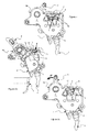
- la
figure 1 représente, en vue perspective, un flasque recouvrant au moins partiellement la manette et la serrure mécanique de l'appareil électrique de l'invention, muni d'un obstacle selon la présente invention ; - la
figure 2 montre, en vue perspective, un déclencheur modifié pour fonctionner selon la présente invention ; - les
figures 3a et 3b montrent l'ensemble manette de commande / serrure mécanique au cours de l'opération de fermeture des contacts ; - la
figure 4 représente, en vue en élévation, l'ensemble manette / serrure mécanique muni d'un flasque comportant l'obstacle de l'invention, et montrant le trajet de l'extrémité de la biellette lors de l'ouverture manuelle des contacts ; et - les
figures 5a et 5b montrent, en vue en élévation, l'ouverture des contacts suite à l'apparition d'un défaut sur une ligne, libérant une extrémité de la biellette (figure 5a ) qui vient heurter l'obstacle (figure 5b ), immobilisant la manette en position intermédiaire de signalisation.
- the
figure 1 represents, in perspective view, a flange at least partially covering the handle and the mechanical lock of the electrical apparatus of the invention, provided with an obstacle according to the present invention; - the
figure 2 shows, in perspective view, a trigger modified to operate according to the present invention; - the
Figures 3a and 3b show the control lever / mechanical lock assembly during the closing operation of the contacts; - the
figure 4 represents, in elevation view, the handle / mechanical lock assembly provided with a flange comprising the obstacle of the invention, and showing the path of the end of the link when the contacts are opened manually; and - the
Figures 5a and 5b show, in elevation view, the opening of the contacts following the appearance of a defect on a line, releasing one end of the link (figure 5a ) that hits the obstacle (figure 5b ), immobilizing the handle in the intermediate signaling position.
En référence à la
Dans la phase d'armement de l'appareil, aboutissant à la fermeture de la ligne électrique, et telle que représentée aux
La représentation de ce flasque (1) est en revanche nécessaire pour l'explication qui correspond à la
Les choses ne se passent pas de la même manière lorsqu'un défaut survient sur la ligne, aboutissant à faire basculer la serrure, comme cela est illustré dans les
Compte tenu de l'éjection de l'extrémité (3b) et de la biellette (3) vers la façade, le trajet t' emprunté par cette dernière, situé un peu plus haut dans le boîtier, interfère avec la position de la protubérance (2) dépassant du flasque (1), comme cela apparaît en
C'est ce positionnement particulier de la manette (8) dans la façade du produit qui indique que l'ouverture des contacts est survenue suite à un incident sur la ligne.It is this particular positioning of the lever (8) in the front of the product which indicates that the opening of the contacts has occurred following an incident on the line.
La protubérance (2) est prévue en un matériau flexible, de telle sorte que la manipulation de la manette (8) dans la direction de la flèche F' soit possible en fléchissant ladite protubérance (2), qui se déforme et laisse passer la biellette (3) en direction de l'assemblage déclencheur (4) / porte-contact (5), de telle sorte que l'extrémité (3b) s'insère entre le bec (10) et l'excroissance (9) pour retrouver sa place et reformer l'équilibre initial biellette (3) / déclencheur (4) / porte-contact (5).The protuberance (2) is provided in a flexible material, so that the manipulation of the handle (8) in the direction of the arrow F 'is possible by bending said protuberance (2), which deforms and lets the rod pass (3) in the direction of the trigger assembly (4) / contact carrier (5), so that the end (3b) is inserted between the spout (10) and the protrusion (9) to recover its place and reform the initial equilibrium link (3) / trigger (4) / contact carrier (5).
La
Cette opération d'acquittement, aboutissant à remettre le produit en position manuelle d'ouverture des contacts (6, 7) réinitialise en quelque sorte le produit, qui peut à nouveau être réarmé de manière à refermer la ligne.This acknowledgment operation, resulting in putting the product in the manual position of opening the contacts (6, 7) somehow resets the product, which can again be reset so as to close the line.
Claims (7)
- Electrical line protection apparatus of the circuit breaker type comprising at least one pair of respectively fixed (7) and movable (6) contacts, a lever (8) for controlling said contacts (6, 7) between a first gap position and a second contact position, said lever (8) being connected to the movable contact (6) by means of a mechanical lock based on a toggle joint comprising, on the one hand, a link rod (3) and, on the other hand, an assembly pivoting against return means and comprising a movable contact holder (5) and a tripping device (4) mounted in relative rotation, the tripping device (4) cooperating with at least one actuator capable of passing on an electrical fault on the line, one of the ends (3a) of the link rod (3) being rotationally mounted on the periphery of the lever (8) and the other end (3b) being positioned in equilibrium in abutment against a protuberance (9) of the contact holder (5) and being held by a tip (10) of the tripping device (4), an action on the tripping device (4) causing it to rotate relative to the contact holder (5) and the lock to tilt under the effect of said return means by breaking said equilibrium, causing the end (3b) of the link rod (3) to be released beyond the protuberance (9) relative to the axis of rotation of the tripping device (4) / contact holder (5) assembly, return means connected to the lever (8) bringing said link rod (3) and its released end (3b) towards the axis of rotation of the lever (8) along a path outside of said assembly, characterised in that it comprises an obstacle (2) placed on said path that blocks the link rod (3) / lever (8) assembly in an intermediate position indicating the tripping of the lock following an electrical fault on a line, said obstacle (2) being at least partly retractable and/or deformable when the force exerted on the lever (8) is greater than the resultant force of the return means of the lever (8), and in that the obstacle comprises a projection (2) extending towards the inside of the frontage of the casing of the apparatus from which the control lever (8) projects, or extending towards the inside of a wall that orients itself substantially parallel to and in the vicinity of said frontage of an element of the shield type (1) integral with the casing and cooperating with the released end (3b) of the link rod (3).
- Electrical line protection apparatus according to the preceding claim, characterised in that at least part of said obstacle (2) is provided in flexible material so that the full rotation of the lever (8) flexibly deforms it by means of the released end (3b) of the link rod (3).
- Electrical line protection apparatus according to claim 1, characterised in that the projection (2) is made up of a flexible material.
- Electrical line protection apparatus according to any one of the preceding claims, characterised in that the wall that orients itself substantially parallel to the frontage of an element of the shield type (1) integral with the casing is flexible at least in the area for attaching the projection (2).
- Electrical line protection apparatus according to any one of the preceding claims, characterised in that the obstacle comprises the projection (2) cooperating with the protuberance (9) of the contact holder (5).
- Electrical line protection apparatus according to any one of the preceding claims, characterised in that the protuberance (9) of the contact holder (5) is flexible.
- Electrical line protection apparatus according to any one of the preceding claims, characterised in that the tip (10) of the tripping device (4) comprises a recess (14) forming a clearance made in a portion that is likely to interfere with the projection (2) during their relative movement.
Applications Claiming Priority (1)
| Application Number | Priority Date | Filing Date | Title |
|---|---|---|---|
| FR1101340A FR2974664B1 (en) | 2011-04-29 | 2011-04-29 | FAULT TRIP INDICATOR BY THE POSITION OF THE KNOB |
Publications (2)
| Publication Number | Publication Date |
|---|---|
| EP2518752A1 EP2518752A1 (en) | 2012-10-31 |
| EP2518752B1 true EP2518752B1 (en) | 2016-09-28 |
Family
ID=46051653
Family Applications (1)
| Application Number | Title | Priority Date | Filing Date |
|---|---|---|---|
| EP12305477.7A Active EP2518752B1 (en) | 2011-04-29 | 2012-04-27 | Fault trip indicator by the position of the handle |
Country Status (2)
| Country | Link |
|---|---|
| EP (1) | EP2518752B1 (en) |
| FR (1) | FR2974664B1 (en) |
Cited By (1)
| Publication number | Priority date | Publication date | Assignee | Title |
|---|---|---|---|---|
| CN110970274A (en) * | 2019-12-23 | 2020-04-07 | 国网江苏省电力有限公司滨海县供电分公司 | Small-sized circuit breaker |
Families Citing this family (3)
| Publication number | Priority date | Publication date | Assignee | Title |
|---|---|---|---|---|
| CN103346047B (en) * | 2013-05-30 | 2016-03-30 | 浙江天正电气股份有限公司 | A kind of miniature circuit breaker of tape jam tripping indicating device |
| CN103413732A (en) * | 2013-08-29 | 2013-11-27 | 温州罗格朗电器有限公司 | Operating mechanism of breaker |
| CN104733253B (en) * | 2015-03-23 | 2017-03-22 | 厦门宏发开关设备有限公司 | Switch disconnector with three-color display function |
Family Cites Families (5)
| Publication number | Priority date | Publication date | Assignee | Title |
|---|---|---|---|---|
| US2828388A (en) * | 1955-11-02 | 1958-03-25 | Fed Pacific Electric Co | Circuit breakers |
| US3183325A (en) * | 1961-05-03 | 1965-05-11 | Fed Pacific Electric Co | Trip indicating circuit breakers |
| EP0338930A1 (en) * | 1988-04-22 | 1989-10-25 | Hager Electro S.A. | Circuit breakers or differential circuit breakers |
| DE3825443A1 (en) * | 1988-07-27 | 1990-02-01 | Asea Brown Boveri | ELECTRICAL SWITCHGEAR |
| FR2649826B1 (en) * | 1989-07-11 | 1995-11-24 | Merlin Gerin | CONTROL MECHANISM FOR ELECTRIC CIRCUIT BREAKER |
-
2011
- 2011-04-29 FR FR1101340A patent/FR2974664B1/en active Active
-
2012
- 2012-04-27 EP EP12305477.7A patent/EP2518752B1/en active Active
Cited By (2)
| Publication number | Priority date | Publication date | Assignee | Title |
|---|---|---|---|---|
| CN110970274A (en) * | 2019-12-23 | 2020-04-07 | 国网江苏省电力有限公司滨海县供电分公司 | Small-sized circuit breaker |
| CN110970274B (en) * | 2019-12-23 | 2022-03-08 | 国网江苏省电力有限公司滨海县供电分公司 | Small-sized circuit breaker |
Also Published As
| Publication number | Publication date |
|---|---|
| EP2518752A1 (en) | 2012-10-31 |
| FR2974664B1 (en) | 2013-12-20 |
| FR2974664A1 (en) | 2012-11-02 |
Similar Documents
| Publication | Publication Date | Title |
|---|---|---|
| EP1975971B1 (en) | Device for controlling an electric protection device and electric protection device including same | |
| EP2518752B1 (en) | Fault trip indicator by the position of the handle | |
| EP1542253B1 (en) | Signalling device indicating the triggering of an electrical protection device | |
| EP2460172B1 (en) | Rotatable control system for electric circuit breaker apparatus | |
| EP1743346B1 (en) | Surge voltage protection device with arc-breaking means | |
| EP2733720B1 (en) | Thermal-magnetic tripping device for tripping a polyphase circuit breaker | |
| EP2975628A1 (en) | Signaling device fault in an electric power protection apparatus and apparatus having such a device | |
| EP2131378A1 (en) | Device for controlling an electrical cut-off device comprising a device for indicating the weld of the contacts, and electrical cut-off device including such a device | |
| EP2377139B1 (en) | Remote control device and circuit breaker with such device | |
| EP2717284B1 (en) | Operating device of an electric protection apparatus and electric protection apparatus comprising same | |
| EP3499541B1 (en) | Electrical protection apparatus comprising a pyrotechnical actuation system | |
| EP3249673B1 (en) | Mechanism for signalling an electrical fault in an electric protection device, and electric protection device including such a mechanism | |
| EP2359379B1 (en) | Control mechanism for a remote-controlled cut-off device, cut-off device, and remote-controlled circuit breaker including such a mechanism | |
| FR2959594A1 (en) | Remote control device for use with cutting device to control remote-controlled circuit breaker, has braking units acting on shaft to break lever when lever is moved toward closing position of mobile and fixed contacts | |
| EP2642502B1 (en) | Trip unit for an electric protection apparatus and electric protection apparatus comprising one such unit | |
| FR2940515A1 (en) | Remote control device for controlling remote-controlled circuit breaker in electrical installation, has driving unit whose mechanism comprises elements displaced in translation along driving axis and displaced in rotation around axis | |
| EP3134910B1 (en) | Device with movable contact without conductive braid | |
| FR2940517A1 (en) | Remote control device for remote-controlled circuit breaker, has detection units to detect position of remote control shaft rotationally mounted around remote control axis, where shaft actuates electrical contacts of interruption device | |
| FR2968439A1 (en) | Manual trigger for limiting inopportune trigger of alarm made by children in e.g. fire detector, has locking units locking flap in closed position, and deactivated by pressure exerted in direction different from direction of opening of flap | |
| FR2940506A1 (en) | Electromechanical actuator for remote control device of remote-controlled circuit breaker, has damping unit having elastic unit cooperating with detachable portion for relative displacement of detachable portion with respect to yoke | |
| FR2462017A1 (en) | Fuse box with verification of fuse capsule insertion - using sprung finger on shoulder of lever in fuse box and linked to signalling device | |
| EP2758977A1 (en) | Electrical line protection device provided with means of indicating an electrical fault on the line | |
| EP0327460A1 (en) | Automatically opening electric switch, in particular a differential interrupter | |
| FR2940512A1 (en) | Remote control locking device for remote control device of remote-controlled circuit breaker, has actuation lever coupled with release lever, and cooperating with retractable part for controlling release of interrupter device | |
| EP1953779A1 (en) | Quick-locking fuse circuit breaker |
Legal Events
| Date | Code | Title | Description |
|---|---|---|---|
| PUAI | Public reference made under article 153(3) epc to a published international application that has entered the european phase |
Free format text: ORIGINAL CODE: 0009012 |
|
| AK | Designated contracting states |
Kind code of ref document: A1 Designated state(s): AL AT BE BG CH CY CZ DE DK EE ES FI FR GB GR HR HU IE IS IT LI LT LU LV MC MK MT NL NO PL PT RO RS SE SI SK SM TR |
|
| AX | Request for extension of the european patent |
Extension state: BA ME |
|
| 17P | Request for examination filed |
Effective date: 20130411 |
|
| GRAP | Despatch of communication of intention to grant a patent |
Free format text: ORIGINAL CODE: EPIDOSNIGR1 |
|
| RIC1 | Information provided on ipc code assigned before grant |
Ipc: H01H 71/52 20060101ALI20160323BHEP Ipc: H01H 71/04 20060101AFI20160323BHEP |
|
| INTG | Intention to grant announced |
Effective date: 20160419 |
|
| GRAS | Grant fee paid |
Free format text: ORIGINAL CODE: EPIDOSNIGR3 |
|
| GRAA | (expected) grant |
Free format text: ORIGINAL CODE: 0009210 |
|
| AK | Designated contracting states |
Kind code of ref document: B1 Designated state(s): AL AT BE BG CH CY CZ DE DK EE ES FI FR GB GR HR HU IE IS IT LI LT LU LV MC MK MT NL NO PL PT RO RS SE SI SK SM TR |
|
| REG | Reference to a national code |
Ref country code: GB Ref legal event code: FG4D Free format text: NOT ENGLISH |
|
| REG | Reference to a national code |
Ref country code: CH Ref legal event code: EP |
|
| REG | Reference to a national code |
Ref country code: AT Ref legal event code: REF Ref document number: 833378 Country of ref document: AT Kind code of ref document: T Effective date: 20161015 |
|
| REG | Reference to a national code |
Ref country code: IE Ref legal event code: FG4D Free format text: LANGUAGE OF EP DOCUMENT: FRENCH |
|
| REG | Reference to a national code |
Ref country code: DE Ref legal event code: R096 Ref document number: 602012023472 Country of ref document: DE |
|
| REG | Reference to a national code |
Ref country code: CH Ref legal event code: NV Representative=s name: DR. GRAF AND PARTNER AG INTELLECTUAL PROPERTY, CH |
|
| REG | Reference to a national code |
Ref country code: LT Ref legal event code: MG4D |
|
| PG25 | Lapsed in a contracting state [announced via postgrant information from national office to epo] |
Ref country code: LT Free format text: LAPSE BECAUSE OF FAILURE TO SUBMIT A TRANSLATION OF THE DESCRIPTION OR TO PAY THE FEE WITHIN THE PRESCRIBED TIME-LIMIT Effective date: 20160928 Ref country code: RS Free format text: LAPSE BECAUSE OF FAILURE TO SUBMIT A TRANSLATION OF THE DESCRIPTION OR TO PAY THE FEE WITHIN THE PRESCRIBED TIME-LIMIT Effective date: 20160928 Ref country code: HR Free format text: LAPSE BECAUSE OF FAILURE TO SUBMIT A TRANSLATION OF THE DESCRIPTION OR TO PAY THE FEE WITHIN THE PRESCRIBED TIME-LIMIT Effective date: 20160928 Ref country code: FI Free format text: LAPSE BECAUSE OF FAILURE TO SUBMIT A TRANSLATION OF THE DESCRIPTION OR TO PAY THE FEE WITHIN THE PRESCRIBED TIME-LIMIT Effective date: 20160928 Ref country code: NO Free format text: LAPSE BECAUSE OF FAILURE TO SUBMIT A TRANSLATION OF THE DESCRIPTION OR TO PAY THE FEE WITHIN THE PRESCRIBED TIME-LIMIT Effective date: 20161228 |
|
| REG | Reference to a national code |
Ref country code: NL Ref legal event code: MP Effective date: 20160928 |
|
| REG | Reference to a national code |
Ref country code: AT Ref legal event code: MK05 Ref document number: 833378 Country of ref document: AT Kind code of ref document: T Effective date: 20160928 |
|
| PG25 | Lapsed in a contracting state [announced via postgrant information from national office to epo] |
Ref country code: LV Free format text: LAPSE BECAUSE OF FAILURE TO SUBMIT A TRANSLATION OF THE DESCRIPTION OR TO PAY THE FEE WITHIN THE PRESCRIBED TIME-LIMIT Effective date: 20160928 Ref country code: GR Free format text: LAPSE BECAUSE OF FAILURE TO SUBMIT A TRANSLATION OF THE DESCRIPTION OR TO PAY THE FEE WITHIN THE PRESCRIBED TIME-LIMIT Effective date: 20161229 Ref country code: NL Free format text: LAPSE BECAUSE OF FAILURE TO SUBMIT A TRANSLATION OF THE DESCRIPTION OR TO PAY THE FEE WITHIN THE PRESCRIBED TIME-LIMIT Effective date: 20160928 Ref country code: SE Free format text: LAPSE BECAUSE OF FAILURE TO SUBMIT A TRANSLATION OF THE DESCRIPTION OR TO PAY THE FEE WITHIN THE PRESCRIBED TIME-LIMIT Effective date: 20160928 |
|
| REG | Reference to a national code |
Ref country code: FR Ref legal event code: PLFP Year of fee payment: 6 |
|
| PG25 | Lapsed in a contracting state [announced via postgrant information from national office to epo] |
Ref country code: RO Free format text: LAPSE BECAUSE OF FAILURE TO SUBMIT A TRANSLATION OF THE DESCRIPTION OR TO PAY THE FEE WITHIN THE PRESCRIBED TIME-LIMIT Effective date: 20160928 Ref country code: EE Free format text: LAPSE BECAUSE OF FAILURE TO SUBMIT A TRANSLATION OF THE DESCRIPTION OR TO PAY THE FEE WITHIN THE PRESCRIBED TIME-LIMIT Effective date: 20160928 |
|
| PG25 | Lapsed in a contracting state [announced via postgrant information from national office to epo] |
Ref country code: PT Free format text: LAPSE BECAUSE OF FAILURE TO SUBMIT A TRANSLATION OF THE DESCRIPTION OR TO PAY THE FEE WITHIN THE PRESCRIBED TIME-LIMIT Effective date: 20170130 Ref country code: SM Free format text: LAPSE BECAUSE OF FAILURE TO SUBMIT A TRANSLATION OF THE DESCRIPTION OR TO PAY THE FEE WITHIN THE PRESCRIBED TIME-LIMIT Effective date: 20160928 Ref country code: SK Free format text: LAPSE BECAUSE OF FAILURE TO SUBMIT A TRANSLATION OF THE DESCRIPTION OR TO PAY THE FEE WITHIN THE PRESCRIBED TIME-LIMIT Effective date: 20160928 Ref country code: AT Free format text: LAPSE BECAUSE OF FAILURE TO SUBMIT A TRANSLATION OF THE DESCRIPTION OR TO PAY THE FEE WITHIN THE PRESCRIBED TIME-LIMIT Effective date: 20160928 Ref country code: ES Free format text: LAPSE BECAUSE OF FAILURE TO SUBMIT A TRANSLATION OF THE DESCRIPTION OR TO PAY THE FEE WITHIN THE PRESCRIBED TIME-LIMIT Effective date: 20160928 Ref country code: IS Free format text: LAPSE BECAUSE OF FAILURE TO SUBMIT A TRANSLATION OF THE DESCRIPTION OR TO PAY THE FEE WITHIN THE PRESCRIBED TIME-LIMIT Effective date: 20170128 Ref country code: BG Free format text: LAPSE BECAUSE OF FAILURE TO SUBMIT A TRANSLATION OF THE DESCRIPTION OR TO PAY THE FEE WITHIN THE PRESCRIBED TIME-LIMIT Effective date: 20161228 Ref country code: CZ Free format text: LAPSE BECAUSE OF FAILURE TO SUBMIT A TRANSLATION OF THE DESCRIPTION OR TO PAY THE FEE WITHIN THE PRESCRIBED TIME-LIMIT Effective date: 20160928 Ref country code: PL Free format text: LAPSE BECAUSE OF FAILURE TO SUBMIT A TRANSLATION OF THE DESCRIPTION OR TO PAY THE FEE WITHIN THE PRESCRIBED TIME-LIMIT Effective date: 20160928 |
|
| REG | Reference to a national code |
Ref country code: DE Ref legal event code: R097 Ref document number: 602012023472 Country of ref document: DE |
|
| PG25 | Lapsed in a contracting state [announced via postgrant information from national office to epo] |
Ref country code: DK Free format text: LAPSE BECAUSE OF FAILURE TO SUBMIT A TRANSLATION OF THE DESCRIPTION OR TO PAY THE FEE WITHIN THE PRESCRIBED TIME-LIMIT Effective date: 20160928 |
|
| PLBE | No opposition filed within time limit |
Free format text: ORIGINAL CODE: 0009261 |
|
| STAA | Information on the status of an ep patent application or granted ep patent |
Free format text: STATUS: NO OPPOSITION FILED WITHIN TIME LIMIT |
|
| 26N | No opposition filed |
Effective date: 20170629 |
|
| PG25 | Lapsed in a contracting state [announced via postgrant information from national office to epo] |
Ref country code: SI Free format text: LAPSE BECAUSE OF FAILURE TO SUBMIT A TRANSLATION OF THE DESCRIPTION OR TO PAY THE FEE WITHIN THE PRESCRIBED TIME-LIMIT Effective date: 20160928 |
|
| GBPC | Gb: european patent ceased through non-payment of renewal fee |
Effective date: 20170427 |
|
| REG | Reference to a national code |
Ref country code: IE Ref legal event code: MM4A |
|
| PG25 | Lapsed in a contracting state [announced via postgrant information from national office to epo] |
Ref country code: MC Free format text: LAPSE BECAUSE OF FAILURE TO SUBMIT A TRANSLATION OF THE DESCRIPTION OR TO PAY THE FEE WITHIN THE PRESCRIBED TIME-LIMIT Effective date: 20160928 |
|
| PG25 | Lapsed in a contracting state [announced via postgrant information from national office to epo] |
Ref country code: GB Free format text: LAPSE BECAUSE OF NON-PAYMENT OF DUE FEES Effective date: 20170427 Ref country code: LU Free format text: LAPSE BECAUSE OF NON-PAYMENT OF DUE FEES Effective date: 20170427 |
|
| REG | Reference to a national code |
Ref country code: BE Ref legal event code: MM Effective date: 20170430 |
|
| REG | Reference to a national code |
Ref country code: FR Ref legal event code: PLFP Year of fee payment: 7 |
|
| PG25 | Lapsed in a contracting state [announced via postgrant information from national office to epo] |
Ref country code: IE Free format text: LAPSE BECAUSE OF NON-PAYMENT OF DUE FEES Effective date: 20170427 |
|
| PG25 | Lapsed in a contracting state [announced via postgrant information from national office to epo] |
Ref country code: BE Free format text: LAPSE BECAUSE OF NON-PAYMENT OF DUE FEES Effective date: 20170430 |
|
| PG25 | Lapsed in a contracting state [announced via postgrant information from national office to epo] |
Ref country code: MT Free format text: LAPSE BECAUSE OF FAILURE TO SUBMIT A TRANSLATION OF THE DESCRIPTION OR TO PAY THE FEE WITHIN THE PRESCRIBED TIME-LIMIT Effective date: 20160928 |
|
| PG25 | Lapsed in a contracting state [announced via postgrant information from national office to epo] |
Ref country code: AL Free format text: LAPSE BECAUSE OF FAILURE TO SUBMIT A TRANSLATION OF THE DESCRIPTION OR TO PAY THE FEE WITHIN THE PRESCRIBED TIME-LIMIT Effective date: 20160928 |
|
| PG25 | Lapsed in a contracting state [announced via postgrant information from national office to epo] |
Ref country code: HU Free format text: LAPSE BECAUSE OF FAILURE TO SUBMIT A TRANSLATION OF THE DESCRIPTION OR TO PAY THE FEE WITHIN THE PRESCRIBED TIME-LIMIT; INVALID AB INITIO Effective date: 20120427 |
|
| PG25 | Lapsed in a contracting state [announced via postgrant information from national office to epo] |
Ref country code: CY Free format text: LAPSE BECAUSE OF NON-PAYMENT OF DUE FEES Effective date: 20160928 |
|
| PG25 | Lapsed in a contracting state [announced via postgrant information from national office to epo] |
Ref country code: MK Free format text: LAPSE BECAUSE OF FAILURE TO SUBMIT A TRANSLATION OF THE DESCRIPTION OR TO PAY THE FEE WITHIN THE PRESCRIBED TIME-LIMIT Effective date: 20160928 |
|
| PG25 | Lapsed in a contracting state [announced via postgrant information from national office to epo] |
Ref country code: TR Free format text: LAPSE BECAUSE OF FAILURE TO SUBMIT A TRANSLATION OF THE DESCRIPTION OR TO PAY THE FEE WITHIN THE PRESCRIBED TIME-LIMIT Effective date: 20160928 |
|
| P01 | Opt-out of the competence of the unified patent court (upc) registered |
Effective date: 20230606 |
|
| PGFP | Annual fee paid to national office [announced via postgrant information from national office to epo] |
Ref country code: DE Payment date: 20240429 Year of fee payment: 13 |
|
| PGFP | Annual fee paid to national office [announced via postgrant information from national office to epo] |
Ref country code: CH Payment date: 20240501 Year of fee payment: 13 |
|
| PGFP | Annual fee paid to national office [announced via postgrant information from national office to epo] |
Ref country code: IT Payment date: 20240422 Year of fee payment: 13 Ref country code: FR Payment date: 20240425 Year of fee payment: 13 |