EP2518570A2 - Image forming apparatus - Google Patents
Image forming apparatus Download PDFInfo
- Publication number
- EP2518570A2 EP2518570A2 EP12165385A EP12165385A EP2518570A2 EP 2518570 A2 EP2518570 A2 EP 2518570A2 EP 12165385 A EP12165385 A EP 12165385A EP 12165385 A EP12165385 A EP 12165385A EP 2518570 A2 EP2518570 A2 EP 2518570A2
- Authority
- EP
- European Patent Office
- Prior art keywords
- development device
- heat receiver
- holder
- image forming
- engagement
- Prior art date
- Legal status (The legal status is an assumption and is not a legal conclusion. Google has not performed a legal analysis and makes no representation as to the accuracy of the status listed.)
- Granted
Links
- 238000011161 development Methods 0.000 claims abstract description 289
- 238000001816 cooling Methods 0.000 claims abstract description 63
- 238000003825 pressing Methods 0.000 claims abstract description 32
- 239000002826 coolant Substances 0.000 claims abstract description 29
- 238000009434 installation Methods 0.000 claims abstract description 29
- 238000003780 insertion Methods 0.000 claims description 47
- 230000037431 insertion Effects 0.000 claims description 47
- 230000007423 decrease Effects 0.000 claims description 10
- ZLMJMSJWJFRBEC-UHFFFAOYSA-N Potassium Chemical compound [K] ZLMJMSJWJFRBEC-UHFFFAOYSA-N 0.000 description 128
- 238000012546 transfer Methods 0.000 description 49
- 108091008695 photoreceptors Proteins 0.000 description 33
- 230000032258 transport Effects 0.000 description 8
- 238000013459 approach Methods 0.000 description 7
- 239000000463 material Substances 0.000 description 7
- 238000009413 insulation Methods 0.000 description 6
- 229910052751 metal Inorganic materials 0.000 description 6
- 239000002184 metal Substances 0.000 description 6
- 230000015572 biosynthetic process Effects 0.000 description 5
- 238000000034 method Methods 0.000 description 4
- 239000002245 particle Substances 0.000 description 4
- 230000008569 process Effects 0.000 description 4
- 238000007711 solidification Methods 0.000 description 4
- 230000008023 solidification Effects 0.000 description 4
- XLYOFNOQVPJJNP-UHFFFAOYSA-N water Substances O XLYOFNOQVPJJNP-UHFFFAOYSA-N 0.000 description 4
- LYCAIKOWRPUZTN-UHFFFAOYSA-N Ethylene glycol Chemical compound OCCO LYCAIKOWRPUZTN-UHFFFAOYSA-N 0.000 description 3
- DNIAPMSPPWPWGF-UHFFFAOYSA-N Propylene glycol Chemical compound CC(O)CO DNIAPMSPPWPWGF-UHFFFAOYSA-N 0.000 description 3
- 238000005299 abrasion Methods 0.000 description 3
- 229910052782 aluminium Inorganic materials 0.000 description 3
- XAGFODPZIPBFFR-UHFFFAOYSA-N aluminium Chemical compound [Al] XAGFODPZIPBFFR-UHFFFAOYSA-N 0.000 description 3
- 238000004140 cleaning Methods 0.000 description 3
- 230000000052 comparative effect Effects 0.000 description 3
- 230000000593 degrading effect Effects 0.000 description 3
- 230000000694 effects Effects 0.000 description 3
- RYGMFSIKBFXOCR-UHFFFAOYSA-N Copper Chemical compound [Cu] RYGMFSIKBFXOCR-UHFFFAOYSA-N 0.000 description 2
- 229910052802 copper Inorganic materials 0.000 description 2
- 239000010949 copper Substances 0.000 description 2
- 238000010586 diagram Methods 0.000 description 2
- 239000000314 lubricant Substances 0.000 description 2
- 238000002844 melting Methods 0.000 description 2
- 230000008018 melting Effects 0.000 description 2
- 238000005192 partition Methods 0.000 description 2
- 229910052700 potassium Inorganic materials 0.000 description 2
- 238000002360 preparation method Methods 0.000 description 2
- 230000001105 regulatory effect Effects 0.000 description 2
- 239000011347 resin Substances 0.000 description 2
- 229920005989 resin Polymers 0.000 description 2
- 230000004044 response Effects 0.000 description 2
- 229910019142 PO4 Inorganic materials 0.000 description 1
- 230000002411 adverse Effects 0.000 description 1
- 230000005540 biological transmission Effects 0.000 description 1
- 230000000903 blocking effect Effects 0.000 description 1
- 239000004020 conductor Substances 0.000 description 1
- 239000000110 cooling liquid Substances 0.000 description 1
- 230000001419 dependent effect Effects 0.000 description 1
- 230000005684 electric field Effects 0.000 description 1
- 230000002708 enhancing effect Effects 0.000 description 1
- 230000008014 freezing Effects 0.000 description 1
- 238000007710 freezing Methods 0.000 description 1
- 230000006870 function Effects 0.000 description 1
- 239000011521 glass Substances 0.000 description 1
- PCHJSUWPFVWCPO-UHFFFAOYSA-N gold Chemical compound [Au] PCHJSUWPFVWCPO-UHFFFAOYSA-N 0.000 description 1
- 229910052737 gold Inorganic materials 0.000 description 1
- 239000010931 gold Substances 0.000 description 1
- 239000004519 grease Substances 0.000 description 1
- 230000002401 inhibitory effect Effects 0.000 description 1
- 229910017053 inorganic salt Inorganic materials 0.000 description 1
- 239000007788 liquid Substances 0.000 description 1
- 239000002075 main ingredient Substances 0.000 description 1
- 238000012423 maintenance Methods 0.000 description 1
- 238000012986 modification Methods 0.000 description 1
- 230000004048 modification Effects 0.000 description 1
- 230000003287 optical effect Effects 0.000 description 1
- NBIIXXVUZAFLBC-UHFFFAOYSA-K phosphate Chemical compound [O-]P([O-])([O-])=O NBIIXXVUZAFLBC-UHFFFAOYSA-K 0.000 description 1
- 239000010452 phosphate Substances 0.000 description 1
- 239000011591 potassium Substances 0.000 description 1
- 229910052709 silver Inorganic materials 0.000 description 1
- 239000004332 silver Substances 0.000 description 1
- 238000004088 simulation Methods 0.000 description 1
- 239000006163 transport media Substances 0.000 description 1
- LWIHDJKSTIGBAC-UHFFFAOYSA-K tripotassium phosphate Chemical compound [K+].[K+].[K+].[O-]P([O-])([O-])=O LWIHDJKSTIGBAC-UHFFFAOYSA-K 0.000 description 1
- 238000003466 welding Methods 0.000 description 1
Images






Classifications
-
- G—PHYSICS
- G03—PHOTOGRAPHY; CINEMATOGRAPHY; ANALOGOUS TECHNIQUES USING WAVES OTHER THAN OPTICAL WAVES; ELECTROGRAPHY; HOLOGRAPHY
- G03G—ELECTROGRAPHY; ELECTROPHOTOGRAPHY; MAGNETOGRAPHY
- G03G15/00—Apparatus for electrographic processes using a charge pattern
- G03G15/06—Apparatus for electrographic processes using a charge pattern for developing
- G03G15/08—Apparatus for electrographic processes using a charge pattern for developing using a solid developer, e.g. powder developer
- G03G15/0896—Arrangements or disposition of the complete developer unit or parts thereof not provided for by groups G03G15/08 - G03G15/0894
-
- G—PHYSICS
- G03—PHOTOGRAPHY; CINEMATOGRAPHY; ANALOGOUS TECHNIQUES USING WAVES OTHER THAN OPTICAL WAVES; ELECTROGRAPHY; HOLOGRAPHY
- G03G—ELECTROGRAPHY; ELECTROPHOTOGRAPHY; MAGNETOGRAPHY
- G03G15/00—Apparatus for electrographic processes using a charge pattern
- G03G15/01—Apparatus for electrographic processes using a charge pattern for producing multicoloured copies
- G03G15/0142—Structure of complete machines
- G03G15/0178—Structure of complete machines using more than one reusable electrographic recording member, e.g. one for every monocolour image
- G03G15/0189—Structure of complete machines using more than one reusable electrographic recording member, e.g. one for every monocolour image primary transfer to an intermediate transfer belt
-
- G—PHYSICS
- G03—PHOTOGRAPHY; CINEMATOGRAPHY; ANALOGOUS TECHNIQUES USING WAVES OTHER THAN OPTICAL WAVES; ELECTROGRAPHY; HOLOGRAPHY
- G03G—ELECTROGRAPHY; ELECTROPHOTOGRAPHY; MAGNETOGRAPHY
- G03G21/00—Arrangements not provided for by groups G03G13/00 - G03G19/00, e.g. cleaning, elimination of residual charge
- G03G21/20—Humidity or temperature control also ozone evacuation; Internal apparatus environment control
-
- G—PHYSICS
- G03—PHOTOGRAPHY; CINEMATOGRAPHY; ANALOGOUS TECHNIQUES USING WAVES OTHER THAN OPTICAL WAVES; ELECTROGRAPHY; HOLOGRAPHY
- G03G—ELECTROGRAPHY; ELECTROPHOTOGRAPHY; MAGNETOGRAPHY
- G03G21/00—Arrangements not provided for by groups G03G13/00 - G03G19/00, e.g. cleaning, elimination of residual charge
- G03G21/20—Humidity or temperature control also ozone evacuation; Internal apparatus environment control
- G03G21/206—Conducting air through the machine, e.g. for cooling, filtering, removing gases like ozone
-
- G—PHYSICS
- G03—PHOTOGRAPHY; CINEMATOGRAPHY; ANALOGOUS TECHNIQUES USING WAVES OTHER THAN OPTICAL WAVES; ELECTROGRAPHY; HOLOGRAPHY
- G03G—ELECTROGRAPHY; ELECTROPHOTOGRAPHY; MAGNETOGRAPHY
- G03G2215/00—Apparatus for electrophotographic processes
- G03G2215/01—Apparatus for electrophotographic processes for producing multicoloured copies
- G03G2215/0103—Plural electrographic recording members
- G03G2215/0119—Linear arrangement adjacent plural transfer points
- G03G2215/0122—Linear arrangement adjacent plural transfer points primary transfer to an intermediate transfer belt
- G03G2215/0125—Linear arrangement adjacent plural transfer points primary transfer to an intermediate transfer belt the linear arrangement being horizontal or slanted
- G03G2215/0129—Linear arrangement adjacent plural transfer points primary transfer to an intermediate transfer belt the linear arrangement being horizontal or slanted horizontal medium transport path at the secondary transfer
Definitions
- the present invention generally relates to an image forming apparatus, such as a copier, a printer, a plotter, or a multifunction machine including at least two of these functions.
- Image forming apparatuses typically include an optical writing device, a fixing device, and a development device. These devices include driving motors, heaters, and the like, all of which act as heat generators that generate heat, thus raising temperature inside the image forming apparatus.
- Development devices include a developer conveyance member to transport developer (e.g., toner) inside the development device, a developer bearer to carry developer thereon, and a developer regulator to adjust the amount of developer carried on the developer bearer.
- developer e.g., toner
- developer bearer to carry developer thereon
- developer regulator to adjust the amount of developer carried on the developer bearer.
- heat is generated by sliding contact between developer and the developer conveyance member as well as contact among developer particles, and temperature inside the development device rises.
- the temperature inside the development device can rise also due to sliding contact between developer and the developer regulator to adjust the amount of developer carried on the developer bearer and contact among developer particles being regulated by the developer regulator.
- the temperature inside the image forming apparatus rises beyond a certain point, the amount of charge of the toner can decrease, making it impossible to attain desired image density. Moreover, the temperature rise can fuse toner and cause the toner to adhere to the developer regulator, the developer bearer, and a latent image bearer (e.g., a photoreceptor).
- the toner adhering to such components can create lines in output images, degrading image quality. In particular, possibility of image failure caused by solidification of toner is higher when toner of a lower melting temperature is used to reduce energy required for image fixing.
- JP-2011-018008-A proposes a liquid-cooling device to cool the development device that generates heat.
- the liquid-cooling device includes a heat receiver containing coolant, a radiator to radiate heat from the coolant, a circulation pipe to circulate the coolant between the heat receiver and the radiator, and a pump to transport the coolant to the heat receiver.
- the heat receiver is disposed in contact with the development device so that the coolant therein draws heat therefrom.
- the cooling efficiency of the liquid-cooling device is higher than that of typical air-cooling devices.
- installing the circulation pipe in a limited space is easier because the circulation pipe for the cooling liquid can be smaller than the air duct. Therefore, the liquid-cooling device is preferable in compact image forming apparatuses in which space between the components is smaller.
- the development device is often designed to be removably installed in the apparatus body independently or together with other components housed in a common unit casing (i.e., a process cartridge).
- the above-described JP-2011-018008-A further proposes a unit to engage the heat receiver with the development device when the development device is installed in the apparatus and disengage it from the development device when the development device is removed from the apparatus.
- the heat receiver is pressed to the development device by a pressing means and held by a holder.
- the holder holding the heat receiver is moved in the direction in which the development device is installed (hereinafter "installation direction").
- installation direction the holder moving in the installation direction shifts the heat receiver toward the development device, and thus the heat receiver is brought into contact with the development device.
- the pressing means presses the heat receiver against the development device.
- an image forming apparatus includes a latent image bearer, a development device removably installable in an apparatus body, a cooling device including a heat receiver containing coolant to draw heat from the development device, a pressing means to press the heat receiver of the cooling device against a side wall of the development device, an engaging and disengaging unit to engage and disengage the heat receiver from the development device by moving the heat receiver in parallel to an installation direction in which the development device is installed in the apparatus body, and a shifting means to move the heat receiver.
- the development device includes a developer bearer to carry developer to a development range facing the latent image bearer. In installation of the development device in the apparatus body, the shifting means contacts the development device and moves the heat receiver together with the development device in the direction in which the development device is installed in the apparatus body.
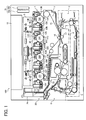
- FIG. 1 is a schematic view illustrating an image forming apparatus according to an embodiment of the present invention
- FIG. 2 is a perspective view of an image forming unit for black from a front side
- FIG. 3 is a perspective view of the image forming unit for black from a back side
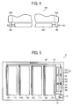
- FIG. 4 is a schematic view of a configuration in which metal rollers are provided in both end portions of a development roller
- FIG. 5 is a schematic view of a liquid-cooling device
- FIG. 6 illustrates a variation of the liquid-cooling device
- FIG. 7 illustrates another variation of the liquid-cooling device
- FIG. 8 illustrates yet another variation of the liquid-cooling device
- FIG 9 is a schematic view of a heat receiver
- FIG 10 is a schematic end-on axial view illustrating a configuration adjacent to the image forming unit for black as viewed from the front side of the apparatus;
- FIG. 11 is a cross-sectional view of the image forming unit for black
- FIG. 12 is a perspective view illustrating the heat receiver and a holder for it
- FIG. 13 is a perspective view illustrating the holder
- FIG. 14 illustrates the holder and the heat receiver as viewed from the front side
- FIG. 15 illustrates an engagement pin fixed in caulking to the holder
- FIG. 16 is a perspective view of the heat receiver
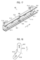
- FIG. 17 is a perspective view illustrating a holder supporter
- FIG. 18 is a schematic view of an engagement slot into which the engagement pin is inserted
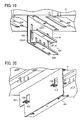
- FIG 19 is a perspective view illustrating a fixed portion and the holder supporter
- FIG 20 is a perspective view illustrating the fixed portion and the holder supporter as viewed from a different angle
- FIG. 21 illustrates a state in which the heat receiver is pressed against a development device
- FIG. 22 illustrates a state in which the heat receiver is disengaged from the development device
- FIG. 23 illustrates insertion of the image forming unit into the apparatus body
- FIG. 24 is an enlarged perspective view illustrating an area A shown in FIG. 23 ;
- FIG. 25 illustrates movement of the engagement pin and a relative position of a contact portion of an engaging and disengaging unit in insertion of the image forming unit into the apparatus
- FIG. 26A illustrates force exerted on the engagement pin guided by an engagement slot having a linear guiding surface as a comparative example
- FIG. 26B illustrates force exerted on the engagement pin guided by the engagement slot whose guiding surface is curved according to an embodiment
- FIG. 27 is a graph that compares loads necessary for insertion of the development device when the guiding surface is linear as shown in FIG. 26A and when the guiding surface is a quadratic curve;
- FIG. 28 illustrates a variation of the guiding surface of the engagement slot.
- FIG. 1 a multicolor image forming apparatus according to an embodiment of the present invention is described.
- FIG. 1 is a schematic view illustrating an image forming apparatus 100 according to the present embodiment.
- the image forming apparatus 100 shown in FIG. 1 includes a tandem image forming unit 1 in which four image forming units 11Y, 11M, 11C, and 11K are arranged in parallel to each other.
- Each image forming unit 11 includes a drum-shaped photoreceptor 18 serving as a latent image bearer, a drum cleaning unit 12, a charging device 13, and two-component type development device 19.
- the components of the image forming unit 11 are housed in a common unit casing, forming a process cartridge (modular unit) removably installable in an apparatus body of the image forming apparatus 100.
- a process cartridge module unit
- An exposure unit 9 serving as a latent image forming unit is provided above the tandem image forming unit 1, and a reading unit 10 is provided in an upper portion of the apparatus.
- the reading unit 10 scans an original placed on an exposure glass, thereby reading image data of the original.
- the intermediate transfer belt 15 is looped around multiple rollers including a support roller 16.
- the secondary-transfer unit 4 includes a secondary-transfer roller 17 disposed in contact with an outer side of the intermediate transfer belt 15 and pressing against the support roller 16 via the intermediate transfer belt 15, thus forming a secondary-transfer nip therebetween.
- a secondary-transfer bias is applied to the secondary-transfer roller 17 from a power source, whereas the support roller 16 is grounded.
- a secondary-transfer electrical field is generated in the secondary-transfer nip.
- a fixing device 7 is provided on the left of the secondary-transfer unit 4 in FIG. 1 to fix toner images formed on sheets of recording media.
- the fixing device 7 includes a hearing roller inside which a heat generator is provided.
- a conveyance belt 6 is provided between secondary-transfer unit 4 and the fixing device 7 to transport the sheet onto which a toner image is transferred to the fixing device 7.
- the image forming apparatus 100 further includes a sheet feeder 3 and a discharge unit 8.
- the sheet feeder 3 is disposed in a lower portion of the apparatus and feeds sheets from a sheet container (i.e., a sheet tray) one by one to the secondary-transfer unit 4.
- the discharge unit 8 transports the sheet that has passed through the fixing device 7 either outside the apparatus or to a duplex unit 5.
- the image forming apparatus 100 further includes an insulation device 20 to thermally insulate the intermediate transfer belt 15 from the fixing device 7.
- the insulation device 20 includes a planar heat receiver 21, a heat pipe 22, a planar radiator 23, a duct 24, and an exhaust fan.
- reference numerals 32 represents a heat receiver (heat receiving portion) of a liquid-cooling device 30 (shown in FIG. 5 )
- 35a represents a cooling fan
- 35b represents a radiator.
- image data of the original is read with the reading unit 10.
- the intermediate transfer belt 15 rotates clockwise in FIG. 1 .
- the charging devices 13 electrically charge the surfaces of the photoreceptors 18 in the respective image forming units 11 of the tandem image forming unit 1.
- the exposure unit 9 exposes the photoreceptors 18 according to yellow, magenta, cyan, and black image data of the original, thus forming latent images on the respective photoreceptors 18.
- the development devices 19 develop the latent images on the respective photoreceptors 18 with developer (e.g., toner) into single-color toner images.
- developer e.g., toner
- the toner images are sequentially transferred from the photoreceptors 18Y, 18M, 18C, and 18K and superimposed on one another on the intermediate transfer belt 15.
- a multicolor toner image i.e., a synthesized image
- the drum cleaning units 12 removes toner remaining on the respective photoreceptors 18 as a preparation for subsequent image formation.
- the sheets are fed from the sheet container one at a time.
- the sheet gets stuck in a nip between registration rollers 14 and is stopped.
- the registration rollers 14 then rotate to send the sheet to the secondary-transfer nip, where the intermediate transfer belt 15 presses against the secondary-transfer unit 4, timed to coincide with the multicolor toner image formed on the intermediate transfer belt 15.
- the multicolor toner image is transferred by the secondary-transfer unit 4 from the intermediate transfer belt 15 onto a first side (e.g., front side) of the sheet (secondary-transfer process).
- the conveyance belt 6 transports the sheet to the fixing device 7, where the toner image is fixed on the sheet with heat and pressure, after which the sheet is transported to the discharge unit 8 .
- the discharge unit 8 includes a switching pawl to switch the destination of the sheet between a discharge tray provided outside the apparatus (on the left in FIG. 1 ) and the duplex unit 5 in the lower portion of the apparatus. The sheet is reversed in the duplex unit 5 and again transported to the secondary-transfer nip (secondary-transfer position) to form an image on a second side of the sheet. Then, the discharge unit 8 discharges the sheet to the discharge tray. Meanwhile, a belt cleaning unit removes the toner remaining on the intermediate transfer belt 15 after the image is transferred therefrom in preparation for subsequent image formation.
- FIGS. 2 and 3 are perspective views of the image forming unit 11K from a front side of the apparatus and a back side of the apparatus, respectively. It is to be noted that only the photoreceptor 18K and the development device 19K are illustrated in FIGS. 2 and 3 for simplicity.
- the photoreceptor 18K includes a photosensitive pipe 18cK on which a photosensitive layer is formed, a front flange 18aK, and a back flange 18bK.
- the front flange 18aK and the back flange 18bK of the photoreceptor 18K are rotatably supported by a housing 110K of the image forming unit 11K.
- the development device 19K includes a development roller 19aK serving as a developer bearer, developer conveyance members, such as conveyance screws, to transport and agitate developer inside the development device 19K, and a developer regulator, such as a doctor blade, to adjust the amount of developer carried on the development roller 19aK.
- a development roller 19aK serving as a developer bearer
- developer conveyance members such as conveyance screws
- a developer regulator such as a doctor blade
- the image forming unit 11K further includes a front positioning plate 111K and a back positioning plate 112K, serving as positioning members for determining the position of the development device 19K in the apparatus body. After the development device 19K is temporarily positioned in the housing 110K, the position thereof is determined by the front positioning plate 111K and the back positioning plate 112K.
- the front positioning plate 111K and the back positioning plate 112K rotatably support a drum shaft 18dK, which is a support shaft of the photoreceptor 18K, as well as a roller shaft 19a1 (shown in FIG. 4 ) of the development roller 19aK.
- the drum shaft 18dK of the photoreceptor 18K extends from a photoreceptor motor 18E provided in the apparatus body.
- a development gap of predetermined size is secured between the photoreceptor 18K and the development roller 19aK.
- the drum shaft 18dK of the photoreceptor 18K rotatably engages the front positioning plate 111K and the back positioning plate 112K via bearings.
- the roller shaft 19a1 of the development roller 19aK rotatably engages the front positioning plate 111K and the back positioning plate 112K via bearings.
- the development device 19K further includes sub-positioning pins 19bK fixed thereto.
- the sub-positioning pin 19bK on the back side engages a sub-positioning slot formed in the back positioning plate 112K.
- the sub-positioning pin 19bK on the front side engages a sub-positioning slot formed in the front positioning plate 111K.
- insertion direction Z On a front side of the apparatus body of the image forming apparatus 100, openings for insertion and removal of the image forming units 11 are formed. It is to be noted that the image forming units 11 are inserted from the front side to the back side, that is, in the direction indicated by arrow Z shown in FIG. 2 (hereinafter "insertion direction Z ").
- the drum shaft 18dK extending from the photoreceptor motor 18E penetrates through the photoreceptor 18K and further engages the bearings of the front positioning plate 111K and the back positioning plate 112K. With this engagement, the position of the photoreceptor 18K is determined with a proper distance secured between the axial centerline of the photoreceptor 18K and the axial centerline of the development roller 19aK. Accordingly, the minute development gap can be kept properly between the photoreceptor 18K and the development roller 19aK, attaining high quality of toner images developed on the photoreceptor 18K.
- Use of resin for the front positioning plate 111K and the back positioning plate 112K is advantageous in the cost and weight.
- the front positioning plate 111K and the back positioning plate 112K may be made of metal.
- rollers 190 may be provided to the respective axial end portions of the roller shaft 19a1 of the development roller 19aK to contact the front and back flanges 18aK and 18bK, respectively, to determine the relative positions of the development roller 19aK and the photoreceptor 18K with a proper development gap kept therebetween.
- the components may be densely packed inside the apparatus.
- the fixing device 7 can be disposed beneath the intermediate transfer unit 2 because the lateral length of the intermediate transfer unit 2 is relatively long.
- the intermediate transfer belt 15 is curved to cover the upper side and the left side of the fixing device 7 in FIG. 1 . This arrangement can reduce the height and the width of the image forming apparatus 100.
- the fixing device 7 thermally affects and causes the intermediate transfer belt 15 to deform, resulting in image failure such as deviation in color registration.
- image failure such as deviation in color registration.
- Such adverse effects become significant as image formation speed increases and the amount of heat generated therein increases.
- the sheet once heated by the fixing device 7 passes through the duplex unit 5 and again contacts the intermediate transfer belt 15 at the secondary-transfer position. Accordingly, the heat from the sheet further increases the temperature of the intermediate transfer belt 15.
- the heat can be transmitted also to the photoreceptors 18 in contact with the intermediate transfer belt 15 and further to the development devices 19, thus increasing the possibility of occurrence of deformation of the intermediate transfer belt 15, solidification of toner, and resultant image failure.
- the insulation device 20 (shown in FIG. 1 ) is provided between the fixing device 7 and the intermediate transfer belt 15 adjacent to the fixing device 7 to thermally insulate them from each other.
- the insulation device 20 in the present embodiment uses a heat pipe, there are insulation devices using a duct to generate a cooling airflow.
- the planar heat receiver 21 is constructed of a material that can absorb heat easily and disposed between the fixing device 7 (heat generator) and the intermediate transfer unit 2 to be protected from heat.
- the heat pipe 22 serves as a heat transmitter and is attached to a lower face of the planar heat receiver 21.
- a first end portion (lower portion in FIG. 1 ) of the heat pipe 22 receives heat, and a second end portion (upper end portion in FIG. 1 ) of the heat pipe 22 is attached to the radiator 23 at a position higher than the heat receiving portion. Heat is released from the second end portion of the heat pipe 22.
- the radiator 23 is constructed of a material capable of releasing heat easily. Further, a heatsink may be provided as required.
- the duct 24 extends from the front side to the back side of the image forming apparatus 100, and the radiator 23 is disposed inside the duct 24.
- An air inlet and an exhaust outlet are provided at first and second ends of the duct 24 on the front side and back side of the apparatus, respectively.
- the exhaust fan is provided in the exhaust outlet on the back side of the apparatus.
- the planar heat receiver 21 receives heat from the fixing device 7, and the heat is transmitted through the heat pipe 22 to the radiator 23 provided in the duct 24, from which the heat is released.
- the exhaust fan discharges the heat outside the apparatus.
- the heat may be subjected to natural cooling.
- the image forming units 11 and the intermediate transfer unit 2 can be insulated from the heat generated in image fixing and thermally protected effectively, thus eliminating or alleviating color deviation caused by deformation of the intermediate transfer belt 15, solidification of toner, and resultant inconveniences.
- the development devices 19 heat is generated by sliding contact between the developer conveyance members and developer as well as contact among developer particles, and temperature inside the development devices 19 increases.
- the temperature inside the development devices 19 can rise also due to sliding contact between developer and the developer regulator to adjust the amount of developer carried on the development roller 19a and contact among developer particles being regulated by the developer regulator.
- the rise in temperature inside the development device 19 can reduce the amount of charge of the toner, making it impossible to attain desired image density. Moreover, the temperature rise can fuse toner and cause the toner to adhere to the developer regulator. The toner adhering to the developer regulator can create lines in output images, degrading image quality. Possibility of image failure caused by solidification of toner is typically higher when toner of a lower melting temperature is used to reduce energy required for image fixing. Additionally, the temperature of the development device 19 tends to increase due to increases in image formation speed.
- liquid cooling is used to cool the development devices 19.
- FIG. 5 is a schematic diagram illustrating the liquid-cooling device 30.
- the liquid-cooling device 30 includes four heat receivers 32Y, 32M, 32C, and 32K, three cooling units 35, a circulation pipe 34 through which coolant is circulated, a cooling pump 31 serving as a transport member to circulate coolant inside the circulation pipe 34, and a reserve tank 33 for containing coolant.
- the heat receivers 32Y, 32M, 32C, and 32K are respectively pressed against side walls 19D (shown in FIG. 10 ) of the development devices 19Y, 19M, 19C, and 19K, which are hot portions.
- the coolant in the heat receivers 32Y, 32M, 32C, and 32K draws heat from the development devices 19Y, 19M, 19C, and 19K, after which the cooling units 35 cool the coolant.
- Each cooling units 35 includes a radiator 35b and a cooling fan 35a. It is to be noted that reference character 32F represents a face the heat receiver 32 facing the development device 19.
- the radiator 35b transmits and releases heat from the coolant via a container containing the coolant.
- the container is formed of a material such as aluminum that has a higher thermal conductivity. Depending on the amount of heat, the heat is released through forced air-cooling using the cooling fan 35a or natural cooling.
- the number of the cooling units 35 is not limited to three. Additionally, although one cooling fan 35a is provided for each cooling unit 35, alternatively, a single common cooling fan may be used to supply external air to all the radiators 35b. By using the multiple cooling units 35, temperature rise in the four development devices 19 can be reliably restricted even when the cooling efficiency of each cooling unit 35 individually is relatively low. As a result, small radiators having a smaller heat-releasing area and lower cooling efficiency can be used, making the cooling unit 35 more compact, compared with a configuration in which only a single cooling unit is used for the four development devices 19.
- the cooling pump 31 is a driving source to circulate the coolant between the heat receivers 32Y, 32M, 32C, and 32K and the cooling units 35 as indicated by arrows shown in FIG. 5 .
- the reserve tank 33 is used to store the coolant.
- the coolant serves as heat transport medium to transport heat from the heat receivers 32Y, 32M, 32C, and 32K to the radiators 35b.
- the coolant includes water as a main ingredient and may further include antirust and propylene glycol or ethylene glycol to lower the freezing temperature. Examples of antirust include phosphate such as potassium phosphate salt and inorganic salt of potassium.
- antirust include phosphate such as potassium phosphate salt and inorganic salt of potassium.
- the coolant that has been cooled by the radiators 35b is supplied to the heat receivers 32Y, 32M, 32C, and 32K in that order and then transported to the reserve tank 33 and the cooling pump 31, after which the coolant is returned to the radiators 35b.
- the sequence is not limited thereto.
- the heat receivers 32Y, 32M, 32C, and 32K may be arranged in parallel as shown in FIG. 6 .
- four cooling units 35Y, 35M, 35C, and 35K may be provided to the development devices 19Y, 19M, 19C, and 19K, respectively, and the circulation pipe 34 may be configured to prevent the coolant cooled in each cooling unit 35 (e.g., 35Y) from flowing to the heat receivers 32 for other development devices 19 (e.g., 19M, 19C, and 19K) while flowing to only the heat receiver 32 for the corresponding development device 19 (e.g., 19Y).
- the image forming apparatus 100 may include two liquid-cooling devices, first and second liquid-cooling devices 30a and 30b.
- the first liquid-cooling device 30a cools the development devices 19Y and 19M
- the second liquid-cooling device 30b cools the development devices 19C and 19K.
- the configuration of the liquid-cooling device 30 can be determined in accordance with thermal conditions such as the amount of heat to be cooled by the heat receivers 32 and temperature.
- FIG. 9 is a schematic diagram that illustrates a configuration of the heat receiver 32K of the liquid-cooling device 30.
- heat receiver 32K As shown in FIG. 9 , five circular recesses 32cK are formed in the heat receiver 32K, and a screw hole 32dK is formed at a center position on a bottom face of each circular recesses 32cK. It is to be noted that the heat receivers 32Y, 32M, 32C, and 32K have a similar configuration, thus omitting the descriptions of the heat receivers 32Y, 32M, and 32C.
- the heat receiver 32K includes a case 32aK in which a coolant channel 32bK is formed.
- the case 32aK and the coolant channel 32bK are constructed of materials of high thermal conductivity.
- copper having a thermal conduction rate of about 400 W/mK or aluminum having a thermal conduction rate of about 200 W/mk can be used as a base of the case 32aK and the coolant channel 32bK of the heat receiver 32K.
- materials of higher thermal conduction rate such as silver or gold may be used.
- the circulation pipe 34 is a flexible member constructed of, for example, rubber or resin, and connected to ends of the coolant channel 32bK.
- the heat receiver 32K is supported movably in the insertion direction Z (shown in FIG. 2 ) and the opposite direction by a unit 40 (shown in FIG. 10 ) for engaging and disengaging the heat receiver 32K from the development device 19K (hereinafter "the engaging and disengaging unit 40").
- the circulation pipe 34 is constructed of a flexible material, the circulation pipe 34 can follow the movement of the heat receiver 32K better and be prevented from being accidentally disengaged from the coolant channel 32bK.
- the circulation pipe 34 is entirely constructed of flexible materials. Forming a part of the circulation pipe 34 with metal is advantageous in reducing transmission of moisture.
- the side walls of the development device 19K may be constructed of a thermally conductive material such as aluminum or copper. In such a case, it is difficult to dispose the heat receiver 32K in contact with the side wall 19D of the development device 19K tightly, and creation of air layers is inevitable. Air layers are not desirable because efficiency in heat exchange is degraded.
- a heat conduction sheet 130K (shown in FIG. 10 ) is bonded to the face 32F of the heat receiver 32K in contact with the development device 19K. It is preferable that the heat conduction sheet 130K have a high thermal conductivity and be deformable in conformity with surface irregularities of the development device 19K and the heat receiver 32K, thus eliminating clearances therebetween. Hardness of heat conduction sheets, however, is proportional to its thermal conductivity, and the heat conduction sheet 130K inevitably becomes relatively hard to attain high thermal conductivity.
- the heat receiver 32K is pressed with a relatively strong force against the side wall 19D of the development device 19K.
- the heat conduction sheet 130K can deform to cancel out the surface irregularities between the development device 19K and the heat receiver 32K even if the hardness thereof is relatively high.
- creation of air layers between the development device 19K and the heat receiver 32K can be inhibited, thereby reliably transmitting heat from the development device 19K to the heat receiver 32K.
- the heat conduction sheet 130K may be bonded to the side wall 19D of the development device 19K.
- the engaging and disengaging units 40 to engage and disengage the heat receivers 32 from the respective development devices 19 is described below.
- the engaging and disengaging units 40 for the heat receiver 32Y, 32M, 32C, and 32K, have a similar configuration.
- the heat receiver 32 is pressed against the side wall 19D of the development device 19 to prevent decreases in cooling efficiency of the development device 19. That is, the development device 19a receives a relatively strong pressing force from the heat receiver 32, and it is possible that the pressing force can affect the front positioning plate 111 and the back positioning plate 112, resulting in deformation of the positioning plates 111 and 112.
- Deformation of the front positioning plate 111 and the back positioning plate 112 can cause fluctuations in the size or position of the development gap.
- the range of tolerance in size or position of the development gap is very narrow. Images can be affected by even a small deviation in development gap caused by slight deformation of the front positioning plate 111 and the back positioning plate 112.
- the heat receiver 32 can fail to contact the development device 19 tightly if the force with which the heat receiver 32 is pressed against the development device 19 is reduced. In such cases, efficiency in cooling of the development device 19 decreases.
- the engaging and disengaging unit 40 is designed to be fixed to the development device 19 when the heat receiver 32 is pressed against the development device 19 so that the force of the heat receiver 32 pressing the development device 19 can act as an inner force not an external force.
- This configuration can prevent the pressing force of the heat receiver 32 from affecting the front positioning plate 111 and the back positioning plate 112 via the development device 19, which is described in further detail below.
- FIG. 10 is a schematic end-on axial view illustrating the configuration adjacent to the image forming unit 11K from the front side of the apparatus.
- FIG. 11 is a cross-sectional view of the image forming unit 11K.
- retractable rails 62a and 62b such as Accuride products, are provided to the apparatus body of the image forming apparatus 100 to engage the image forming unit 19K.
- the image forming unit 11K is set on the rails 62a and 62b and inserted into the apparatus body with the drum shaft 18dK inserted into the photoreceptor 18K.
- the development device 19K is provided with the engaging and disengaging unit 40K to engage and disengage the heat receiver 32K from the development device 19K.
- the engaging and disengaging unit 40K includes a holder 41K for holding the heat receiver 32K of the liquid-cooling device 30 and a holder supporter 42K for supporting the holder 41K so that the holder 41K can engage and be disengaged from the development device 19K.
- the rail 62a on the left in FIG. 10 is fixed to a fixed portion 50K of the apparatus body, and the holder supporter 42K is fixed to the fixed portion 50K.
- the fixed portion 50 is fixed to a partition 61 separating the tandem image forming unit 1 from the image writing area in which the exposure unit 9 is provided.
- the holder 41K covers three sides of the heat receiver 32K, that is, an upper face, a lower face, and a face 32G of the heat receiver 32K.
- the face 32G is opposite the face 32F that is pressed against the side wall 19D of the development device 19K.
- the heat receiver 32K can be shielded from infrared light from the fixing device 7 and the like, thus reducing thermal effects on the heat receiver 32K from components other than the development device 19K.
- the heat receiver 32K is noted heated by components other than the development device 19K, securing efficiency in cooling of the development device 19K.
- FIG. 12 is a perspective view illustrating the holder 41K holding the heat receiver 32K
- FIG. 13 is a perspective view illustrating the holder 41K
- FIG. 14 illustrates the holder 41K and the heat receiver 32K as viewed from the front side.
- the holder 41K can be produced by folding a planar metal, and five holes 41bK are formed in an opposed wall 41aK opposed to the face 32G of the heat receiver 32K.
- the holes 41bK are arranged at regular intervals in the longitudinal direction of the holder 41K.
- the holder 41K further includes first and second folded portions 41cK and 41dK (shown in FIG. 14 ) folded at both ends of the opposed wall 41aK in the shorter direction of the opposed wall 41aK.
- An engagement hole 41eK is formed in a center portion of each of the first and second folded portions 41cK and 41dK in the longitudinal direction thereof.
- engagement pins 140K serving as engagement members are fitted in the respective engagement holes 41eK in caulking.
- the first folded portion 41cK of the holder 41K extends longer to the back side (upper right in FIG. 13 ) of the apparatus than the second folded portion 41dK as shown in FIG. 13 , forming an extended portion 41gK, and a contact portion 41fK is provided to the extended portion 41gK.
- the contact portion 41fK is positioned in a downstream end portion of the holder 41K in the insertion direction Z and includes a face perpendicular to the insertion direction Z (shown in FIG. 2 ) of the development device 19K or the longitudinal direction of the development device 19K.
- the contact portion 41fK contacts a back end portion of a first engagement portion 191K (shown in FIG.
- the contact portion 41fK can be formed by folding. It is to be noted that the insertion direction Z of the development device 19K is perpendicular to the surface of the paper on which FIGS. 10 and 11 are drawn.
- the five circular recesses 32cK formed in the heat receiver 32K are positioned to face the five holes 41bK formed in the opposed wall 41aK of the holder 41K.
- a step screw 141K is fitted loosely in each of the five holes 41bK formed in the opposed wall 41 aK of the holder 41K, and further a threaded portion of the step screw 141K is screwed in the screw hole 32dK of the heat receiver 32K.
- a coil spring 142K winds around a step portion of the step screw 141K as shown in FIG. 14 .
- the coil spring 142K is an elastic member that serves as a pressing means.
- the coil spring 142K has a first end disposed in contact with the opposed wall 41 aK of the holder 41K and a second end disposed in contact with a bottom portion 32eK (hereinafter also "contact portion 32ek") of the circular recesses 32cK formed in the heat receiver 32K.
- the bottom portion 32eK of the circular recesses 32cK serves as a contact portion with which the pressing means (coil spring 142K) comes into contact.
- the heat receiver 32K is pushed by the coil spring 142K toward the development device 19K and held by the holder 41K.
- the holder 41K supports the heat receiver 32K with a clearance of predetermined size provided between the opposed wall 41aK and the face 32G of the heat receiver 32K on the opposite side of the development device 19K.
- the heat receiver 32K is supported so that the face 32F thereof projects beyond ends of the first and second folded portions 41cK and 41dK in the lateral direction in FIG. 11 .
- the ends of the first and second folded portions 41cK and 41dK of the holder 41K can be prevented from contacting the development device 19K.
- the force with which the heat receiver 32K presses against the development device 19K can be easily adjusted by changing the type of the elastic pressing member that in the present embodiment is the coil spring 142K.
- the circular recesses 32cK is formed in the heat receiver 32K, and the contact portion (bottom portion) 32eK is recessed beyond the face 32G on the opposite side of the face 32F in contact with the development device 19K.
- a distance D1 between the contact portion 32eK and the opposed wall 41aK of the holder 41K can be greater than a distance D2 between the opposed wall 41aK and the face 32G of the heat receiver 32K on the opposite side of the development device 19K.
- This configuration can reduce fluctuations in pressing force exerted by the coil spring 142K due to fluctuation in length of the coil spring 142K.
- the apparatus can become compact because the distance D2 between the opposed wall 41aK and the face 32G of the heat receiver 32K can be reduced.
- the heat receiver 32K is elastically supported at multiple positions spaced at regular intervals in the longitudinal direction. Accordingly, the pressing force can be uniformly applied to the heat receiver 32K.
- the holes 41bK in the opposed wall 41aK of the holder 41K are arranged in a row in the longitudinal direction in the present embodiment, alternatively, the holes 41bK may be in zigzag arrangement.
- the heat receiver 32K is elastically supported at five positions in the present embodiment, the number and locations at which the heat receiver 32K is supported is not limited thereto as long as the pressure can be applied from the entire heat receiver 32K to the development device 19K uniformly. Additionally, if a sufficient distance is secured between the opposed wall 41aK and the face 32G of the heat receiver 32K on the opposite side of the development device 19K, the circular recesses 32cK may be unnecessary.
- the pressing means for exerting the pressure force is not limited to the coil spring 142K but may be a leaf spring or sponge capable of restoring its elastic force. When sponge or the like is used, it is not necessary to use the step screw 141K to support it. Sponge may be glued to both the heat receiver 32K and the holder 41K so that the heat receiver 32K is supported on the holder 41K with the sponge.
- FIG. 17 is a perspective view of the holder supporter 42K.
- the holder supporter 42K includes a first member 421K and a second member 422K.
- the first member 421K includes a vertical wall 421aK, a supporting portion 421bK, and a fixed portion 421cK.
- the first member 421K can be produced by folding a metal sheet. That is, the metal sheet is folded at both ends of the vertical wall 421 aK in a shorter direction of the vertical wall 421aK, thereby forming the supporting portion 421bK and the fixed portion 421cK.
- a connecting portion 421dK to connect the holder supporter 42K to the fixed portion 50K is provided to either end portion of the supporting portion 421bK in the longitudinal direction thereof, and a slot 421eK is formed in a center portion of each connecting portion 421dK.
- a screw hole 421-1 is formed in either end portion of the fixed portion 421cK of the first member 421K in the longitudinal direction to connect the second member 422K to the first member 421K with a screw.
- An engagement slot 423K that engages the engagement pin 140K is formed in a center portion in the longitudinal direction of each of the supporting portion 421bK of the first member 421K and the second member 422K. As shown in FIG. 18 , the engagement slot 423K includes a guiding portion 423aK oblique to the insertion direction Z of the development device 19K (longitudinal direction of the holder supporter 42K) and an engagement portion 423bK in parallel to the insertion direction Z of the development device 19K.
- the engagement pin 140K moves while being in contact with a guiding face 423cK (on the left in FIG. 18 ) of the guiding portion 423aK, that is, guided by the guiding face 423cK, and a part of the guiding face 423cK is curved.
- reference character A represents a start point of the curved face of the engagement slot 423K
- B represents an end point of the curved face.
- Lubricant such as grease is applied to the guiding face 423cK, along which the engagement pin 140K moves, to alleviate frictional resistance generated when the engagement pin 140K moves inside the engagement slot 423K.
- the resistance against insertion of the development device 19 can be alleviated better.
- the holder 41K can be connected to the holder supporter 42K as follows.
- the engagement pin 140K which is fixed in caulking to the hole 41eK formed in the first folded portion 41cK of the holder 41K, is inserted into the engagement slot 423K formed in the supporting portion 421bK of the holder supporter 42K.
- the other engagement pin 140K which is fixed in caulking to the hole 41eK formed in the second folded portion 41dK of the holder 41K, is inserted into the engagement slot 423K formed in the second member 422K of the holder supporter 42K.
- the second member 422K is screwed to the fixed portion 421cK of the first member 421K of the holder supporter 42K.
- the holder 41K can be supported by the holder supporter 42K.
- the supporting portion 421bK is positioned on the upper side of the first member 421K as shown in FIG. 19 in the present embodiment, alternatively, the supporting portion 421bK may be disposed on the lower side.
- the second member 422K is screwed to the fixed portion 421cK of the first member 421K in the configuration shown in the drawings, alternatively, the second member 422K may be fixed thereto using a rivet or welding. It is advantageous in that maintenance work of the heat receiver 32K can be easier when the first member 421K and the second member 422K are fixed using screws so that they can be separated easily.
- the holder supporter 42K further includes first and second engagement rims 161K and 162K.
- the first and second engagement rims 161K and 162K are provided at an end in the shorter direction of the first member 421K and the second member 422K, respectively.
- the first and second engagement rims 161K and 162K extend in the insertion direction Z (longitudinal direction) and are folded upward from the ends in the shorter direction of the first and second members 421K and 422K.
- the development device 19K includes first and second receiving rims 191K and 192K extending in the insertion direction Z (longitudinal direction of the development device 19K).
- the first receiving rim 191K is formed with a horizontal portion projecting from the side wall 19D of the development device 19K and a vertical portion extending downward from the end of the horizontal projecting portion.
- the second receiving rim 192K projects downward from a bottom face of the development device 19K and positioned in an end portion on the side of the heat receiver 32K.
- the first engagement rim 161K faces the first receiving rim 191K and is positioned closer to the photoreceptor 18K than the first receiving rim 191K.
- the second engagement rim 162K faces the second receiving rim 192K and is positioned closer to the photoreceptor 18K than the second receiving rim 192K.
- the holder supporter 42K is fixed to the fixed portion 50K that is screwed to the partition 61 at three positions 50SR. More specifically, as shown in FIG. 20 , the fixed portion 50K includes holder supporter mounts 51K in both longitudinal end portions. A step screw 150K is loosely fitted in the slot 421eK formed in the connecting portion 421dK of the holder supporter 42K, and, as shown in FIG. 20 , the step screw 150K is screwed into a screw hole formed in a center portion of the holder supporter mount 51K provided in the fixed portion 5 oak.
- a clearance is provided between the fixed portion 50K and the vertical wall 421aK of the holder supporter 42K attached to the fixed portion 50K.
- the holder supporter 42K can move swingably in parallel to the direction in which the coil spring 142K exerts the pressing force and relatively to the fixed portion 50K, the holder supporter 42K cannot move in the insertion direction Z of the development device 19K.
- the holder supporter 42K can move swingably in parallel to the pressing direction of the coil spring 142K, the first and second engagement rims 161K and 162K at the right end of the holder supporter 42K can be prevented from blocking the first and second receiving rims 191K and 192K of the development device 19K being inserted or removed from the apparatus. Accordingly, the development device 19K can be smoothly inserted and removed from the apparatus. Further, when the coil spring 142K presses the heat receiver 32K against the development device 19K, the holder supporter 42K can move away from the development device 19K receiving reaction force from the development device 19K. As a result, the first and second engagement rims 161K and 162K can engage the first and second receiving rims 191K and 192K, respectively, and the engaging and disengaging unit 40K can be fixed to the development device 19K.
- FIG. 21 illustrates a state in which the heat receiver 32K is pressed against the development device 19K
- FIG. 22 illustrates a state in which the heat receiver 32K is disengaged from the development device 19K
- FIG. 23 illustrates insertion of the image forming unit 11K into the apparatus body
- FIG. 24 is an enlarged perspective view illustrating an area A shown in FIG. 23 . It is to be noted that not the entire image forming unit 11K but only the casing of the development device 19K is illustrated in FIGS. 23 and 24 for simplicity.
- the downstream end portion in the insertion direction Z of the first receiving rim 191K which is a projection projecting toward the heat receiver 32K, comes into contact with the contact portion 41fK provided to the holder 41K.
- the first receiving rim 191K pushes the contact portion 41fK, and the holder 41K is moved downstream in the insertion direction Z (toward the back side of the apparatus body) together with the development device 19K. Then, as shown in FIG.
- the engagement pin 140K of the holder 41K moves inside the engagement slot 423K guided by the guiding portion 423aK, and the holder 41K moves toward the development device 19K. Accordingly, the heat receiver 32K held by the holder 41K moves toward the development device 19K in conjunction with insertion of the development device 19K.
- the contact portion 41fK of the holder 41K and the first receiving rim 191K of the development device 19K together form a shifting unit (shifting means) for moving the heat receiver 32K.
- the holder 41K approaches the development device 19K while moving together with the development device 19K to the back side of the apparatus. Then, the heat receiver 32K comes into contact with the side wall 19D of the development device 19K. At that time, referring to FIG. 18 , the engagement pin 140K is at a start point A of the curved portion of the guiding face 423cK.
- the holder 41K moves to the back side of the apparatus together with the development device 19K. Then, the engagement pin 140K is guided by the curved portion of the guiding face 423cK, and the holder 41K further approaches the development device 19K. As a result, the heat receiver 32K in contact with development device 19K presses the development device 19K. Then, the development device 19K as well as the holder 41K moves to the back side of the apparatus.
- the engagement pin 140K is guided to the engagement portion 423bK of the engagement slot 423K as shown in FIG. 25 , the heat receiver 32K presses against the side wall 19D of the development device 19K with a predetermined pressure.
- the heat conduction sheet 130K of the heat receiver 32K does not slidingly contact the development device 19K because the holder 41K presses the heat receiver 32K to the development device 19K while moving to the back side of the apparatus together with the development device 19K as described above.
- This configuration can prevent damage to the heat conduction sheet 130K caused by the sliding contact with the development device 19K. Accordingly, the heat conduction sheet 130K can be kept in close contact with the side wall 19D of the development device 19K for long time. As a result, the development device 19K can be cooled sufficiently for long time.
- reaction force from the development device 19K is transmitted to the holder supporter 42K via the heat receiver 32K and the engagement pin 140K of the holder 41K. Accordingly, the holder supporter 42K is pushed away from the development device 19K. Receiving the reaction force from the development device 19K, the holder supporter 42K moves away from the development device 19K as indicated by arrow A1 shown in FIG.
- the holder supporter 42K is fixed to the fixed portion 50K movably in parallel to the direction of the pressing force exerted by the coil spring 142K.
- the first and second receiving rims 191K and 192K of the development device 19K respectively contact the first and second engagement rims 161K and 162K of the engaging and disengaging unit 40K and engage them.
- the holder supporter 42K no longer moves in the direction indicated by arrow A1 in FIG. 21 even if the development device 19K applies reaction force thereto. Accordingly, the coil spring 142K is compressed and presses the heat receiver 32K against the development device 19K. At that time, the holder 41K receives the reaction force against the pressing force exerted on the coil spring 142K by the heat receiver 32K, and further the reaction force is received by the holder supporter 42K via the engagement pin 140K.
- the reaction force affects the first and second receiving rims 191K and 192K of the development device 19K in contact with the first and second engagement rims 161K and 162K of the holder supporter 42K.
- the engaging and disengaging unit 40K is fixed to the development device 19K so that the development device 19K and the engaging and disengaging unit 40K can act as a single united element inside the apparatus.
- the pressing force by the heat receiver 32K can act as not an external force on the development device 19K but an internal force inside the development device 19K. Consequently, the force exerted on the front and back positioning plates 111K and 112K and the like, resulting from the pressing force from the heat receiver 32K, can be reduced, thus inhibiting deformation of the front positioning plate 111K and the back positioning plate 112K. Accordingly, fluctuations in the development gap can be reduced, and high image quality can be maintained for long time.
- the heat receiver 32K can push the development device 19K with a predetermined pressure.
- the engagement pin 140K moves while being in contact with the curved portion of the guiding face 423cK of the guiding portion 423aK. Therefore, increases in resistance against insertion of development device 19K can be limited.
- the heat receiver 32K is pushed to the development device 19K. More specifically, as the holder 41K approaches the development device 19K, being guided by the guiding portion 423aK of the engagement slot 423K, the coil spring 142K is compressed. Accordingly, the force with which the heat receiver 32K presses against the development device 19K increases. As a result, the reaction force applied to the engagement pin 140K increases.
- FIG 26A illustrates a guiding portion 423aZ having a linear guiding face 423cZ as a comparative example.
- reaction force F1 applied to an engagement pin 140Z is not so strong.
- resistance F1a caused by the engagement pin 140Z moving to the right in FIG. 26A is not so strong.
- the coil spring 142K is compressed. Reaction force F2 applied to the engagement pin 140K at that time is greater than the force F1.
- resistance F2a generated to move the engagement pin 140Z to the upper right in FIG. 26A at that time becomes greater than the resistance F1a. Accordingly, when frictional resistance is disregarded, the resistance against insertion of the image forming unit 11K increases by the amount corresponding to the drag (F2a-F1a).
- the resistance against insertion of the image forming unit 11K can be kept substantially constant from the initial state when the heat receiver 32K comes into contact with development device 19K until the engagement pin 140K approaches the engagement portion 423bK.
- the guiding face 423c can be shaped so that its inclination relative to the installation direction Z decreases toward the engagement portion 423b.
- the resistance can be substantially constant while the engagement pin 140K moves along the guiding portion 423aK of the engagement slot 423K. Accordingly, the resistance against insertion of the image forming unit 11K can be kept constant.
- FIG. 27 is a graph of load (linear line A) necessary for insertion of the development device 19K when the guiding surface 423cK of the guiding portion 423aK is linear as shown in FIG. 26A and load (linear line B) necessary for insertion of the development device 19K when the guiding surface 423cK is a quadratic curve. It is to be noted that FIG. 27 shows results generated in simulation with the frictional resistance between the guiding face 423cK and the engagement pin 140K deemed zero, and reference character L represents the amount by which the development device 19 is moved (insertion amount) to complete insertion thereof.
- the user operates a lever provided on the front side of the apparatus to move the holder 41K toward the front side. Then, pushed by the contact portion 41fK, the image forming unit 11K (development device 19K) moves to the front side of the apparatus together with the holder 41K.
- the engagement pin 140K of the holder 41K reaches the guiding portion 423aK of the engagement slot 423K and is guided by the guiding portion 423aK, the holder 41K moves relatively to the holder supporter 42K in the direction away from the development device 19K. Accordingly, the heat receiver 32K held by the holder 41K moves away from the development device 19K.
- the heat receiver 32K When the engagement pin 140K reaches an end portion of the guiding portion 423aK, the heat receiver 32K is completely disengaged from the development device 19K as shown in FIG. 22 . When the heat receiver 32K is thus disengaged, the user pulls out the development device 19K from the apparatus body. In removal of the image forming unit 11K from the apparatus body, the heat receiver 32K is moved away from the development device 19K and does not apply pressure to the development device 19K. Additionally, the first and second engagement rims 161K and 162K are disengaged from the first and second receiving rims 191K and 192K and move relatively to the first and second receiving rims 191K and 192K in parallel to the insertion direction Z.
- the image forming unit 11K can be pulled out from the apparatus body easily.
- the shifting means in removal of the image forming unit 11K from the apparatus body, sliding contact between the heat conduction sheet 130K and the development device 19K can be reduced, thus reducing abrasion of the heat conduction sheet 130K.
- the guiding portion 423aK of the engagement slot 423K has the guiding face 423cK of quadratic curve in the description above, the guiding portion 423aK is not limited thereto.
- FIG. 28 illustrates an engagement slot 4231 as a variation.
- a guiding portion 423a1 of the engagement slot 4231 includes first and second inclined portions 423a-1 and 423a-2 each having a linear guiding face (guiding face 423c1).
- the second inclined portion 423a-2 on the side of the engagement portion 423b is inclined from the insertion direction Z by an angle (hereinafter "inclination angle") ⁇ 2 smaller than an inclination angle ⁇ 1 of the first inclined portion 423a-1.
- the inclination relative to the insertion direction Z decreases toward the engagement portion 423b.
- the engagement pin 140K can be guided by the second inclined portion 423a-2 whose inclination is smaller when the reaction force of the engagement pin 140K increases in response to the increase in the pressing force exerted on the development device 19K by the heat receiver 32. Accordingly, increases in the drag generated when the engagement pin 140K moves inside the guiding portion 423a1 can be limited, and thus increases in the resistance against insertion of the development device 19K can be limited. It is to be noted that although there are two inclined portions in the configuration shown in FIG. 28 , the number of inclined portions into which the guiding portion 423a is divided is not limited thereto. In such cases, the inclination of the inclined portion is reduced toward the engagement portion 423b similarly.
- the development device 19 may be designed to be independently installed and removed from the apparatus body although the relative positions of the development device 19 and the photoreceptor 18 are determined with the positioning plates, and the development device 19 and the photoreceptor 18 are united into a single unit removably installed in the apparatus body in the above-described configuration.
- a positioning member inside the apparatus body determines the position of the development device 19 so that the gap between the photoreceptor 18 and the development roller 19a can be kept properly.
- the image forming apparatus 100 includes the photoreceptor 18 serving as the latent image bearer, the development device 19 removably installed in the apparatus body, the liquid-cooling device 30 including the heat receiver 32, and the engaging and disengaging unit 40.
- the development device 19 includes the development roller 19a serving as the developer bearer.
- the heat receiver 32 contains coolant to draw heat from the development device 19, and the coil spring 142 presses the heat receiver 32 against the side wall of the development device 19.
- the engaging and disengaging unit 40 moves the heat receiver 32 in the insertion direction Z of the development device 19K, thereby engaging and disengaging the heat receiver 32 from the development device 19.
- the image forming apparatus 100 further includes the shifting means to move the heat receiver 32.
- the image forming apparatus 100 further includes the first and second positioning plates 111 and 112 to fix in position the development device 19 relative to the photoreceptor 18.
- the shifting means is designed to contact the development device 19 in installation of the development device 19 in the apparatus body and to move the heat receiver 32 together with the development device 19 in the installation direction Z.
- the shifting means to move the heat receiver 32 includes the first receiving rim 191 provided to the development device 19 and the contact portion 41f provided to the engaging and disengaging unit 40 and designed to contact the first receiving rim 191.
- the first receiving rim 191 projects toward the heat receiver 32.
- the heat receiver 32 can move in the installation direction Z together with the development device 19.
- the engaging and disengaging unit 40 includes the holder 41 to hold the heat receiver 32 via the coil spring 142, and the holder supporter 42 to support the holder 41 movably in the installation direction Z of the development device 19.
- the holder 41 includes the engagement pin 140
- the holder supporter 42 includes the engagement slot 423 that engages with the engagement pin 140.
- the engagement slot 423 includes the guiding portion 423a and the engagement portion 423b.
- the guiding portion 423a is inclined relative to the installation direction Z of the development device 19.
- the guiding portion 423a guides the engagement pin 140 close to and away from the development device 19 while moving the engagement pin 140 in parallel to the installation direction Z.
- the engagement portion 423b extends in the insertion direction Z and designed to retain the engagement pin 140 when the heat receiver 32 is pressed against the side wall 19D of the development device 19.
- the heat receiver 32 can be engaged and disengaged from the development device 19 by operating the holder 41. Additionally, the holder 41 can be prevented from accidentally disengaged from the holder supporter 42.
- the guiding portion 423a is designed so that its inclination relative to the installation direction Z decreases toward the engagement portion 423b. This configuration can restrict increases in drag when the engagement pin 140 moves along the guiding face 423c of the guiding portion 423 a even if, in insertion of the development device 19, the pressing force exerted on the development device 19 from the heat receiver 32 increases, and the resistance applied to engagement pin 140 due to the pressing force increases.
- the holder 41 heat receiver 32
- resistance against insertion of the development device 19 can be restricted. Therefore, a strong force is not necessary for insertion of the development device 19, thus enhancing usability.
- the engaging and disengaging unit 40 further includes the first and second engagement rims 161 and 162.
- the first and second engagement rims 161 and 162 are engaged with the first and second receiving rims 191 and 192 by the reaction against the pressure exerted by the heat receiver 32 on the coil spring 142.
- the engaging and disengaging unit 40 is fixed to the development device 19.
- the reaction against the pressing force exerted on the coil spring 142 by the heat receiver 32 can affect the receiving rims 191 and 192 of the development device 19.
- the pressure applied from the heat receiver 32 to the development device 19 can become an internal force, thus reducing the force applied to the positioning plates 111 and 112 from the development device 19 due to the pressure exerted by the heat receiver 32. Therefore, fluctuations in the gap between the photoreceptor 18 and the development device 19 can be restricted.
Landscapes
- Physics & Mathematics (AREA)
- General Physics & Mathematics (AREA)
- Life Sciences & Earth Sciences (AREA)
- Engineering & Computer Science (AREA)
- Atmospheric Sciences (AREA)
- Biodiversity & Conservation Biology (AREA)
- Ecology (AREA)
- Environmental & Geological Engineering (AREA)
- Environmental Sciences (AREA)
- Electrophotography Configuration And Component (AREA)
- Control Or Security For Electrophotography (AREA)
Abstract
Description
- The present invention generally relates to an image forming apparatus, such as a copier, a printer, a plotter, or a multifunction machine including at least two of these functions.
- Image forming apparatuses typically include an optical writing device, a fixing device, and a development device. These devices include driving motors, heaters, and the like, all of which act as heat generators that generate heat, thus raising temperature inside the image forming apparatus.
- Development devices include a developer conveyance member to transport developer (e.g., toner) inside the development device, a developer bearer to carry developer thereon, and a developer regulator to adjust the amount of developer carried on the developer bearer. For example, in the development device, heat is generated by sliding contact between developer and the developer conveyance member as well as contact among developer particles, and temperature inside the development device rises. The temperature inside the development device can rise also due to sliding contact between developer and the developer regulator to adjust the amount of developer carried on the developer bearer and contact among developer particles being regulated by the developer regulator.
- When the temperature inside the image forming apparatus rises beyond a certain point, the amount of charge of the toner can decrease, making it impossible to attain desired image density. Moreover, the temperature rise can fuse toner and cause the toner to adhere to the developer regulator, the developer bearer, and a latent image bearer (e.g., a photoreceptor). The toner adhering to such components can create lines in output images, degrading image quality. In particular, possibility of image failure caused by solidification of toner is higher when toner of a lower melting temperature is used to reduce energy required for image fixing.
- In view of the foregoing, various approaches have been tried to cool such hot portions. For example,
JP-2011-018008-A - Additionally, the development device is often designed to be removably installed in the apparatus body independently or together with other components housed in a common unit casing (i.e., a process cartridge).
- The above-described
JP-2011-018008-A - However, if the heat receiver slides on the development device, it is possible that the heat receiver is abraded and damaged. Such abrasion hinders close contact between the heat receiver and the development device, thereby degrading cooling effects.
- It is a general object of the present invention to provide an improved and useful image forming apparatus in which the above-described problems are eliminated. In order to achieve the above-described object, there is provided an image forming apparatus according to
claim 1. Advantageous embodiments are defined by the dependent claims. - Advantageously, an image forming apparatus includes a latent image bearer, a development device removably installable in an apparatus body, a cooling device including a heat receiver containing coolant to draw heat from the development device, a pressing means to press the heat receiver of the cooling device against a side wall of the development device, an engaging and disengaging unit to engage and disengage the heat receiver from the development device by moving the heat receiver in parallel to an installation direction in which the development device is installed in the apparatus body, and a shifting means to move the heat receiver. The development device includes a developer bearer to carry developer to a development range facing the latent image bearer. In installation of the development device in the apparatus body, the shifting means contacts the development device and moves the heat receiver together with the development device in the direction in which the development device is installed in the apparatus body.
- A more complete appreciation of the disclosure and many of the attendant advantages thereof will be readily obtained as the same becomes better understood by reference to the following detailed description when considered in connection with the accompanying drawings, wherein:
-
FIG. 1 is a schematic view illustrating an image forming apparatus according to an embodiment of the present invention; -
FIG. 2 is a perspective view of an image forming unit for black from a front side; -
FIG. 3 is a perspective view of the image forming unit for black from a back side; -
FIG. 4 is a schematic view of a configuration in which metal rollers are provided in both end portions of a development roller; -
FIG. 5 is a schematic view of a liquid-cooling device; -
FIG. 6 illustrates a variation of the liquid-cooling device; -
FIG. 7 illustrates another variation of the liquid-cooling device; -
FIG. 8 illustrates yet another variation of the liquid-cooling device; -
FIG 9 is a schematic view of a heat receiver; -
FIG 10 is a schematic end-on axial view illustrating a configuration adjacent to the image forming unit for black as viewed from the front side of the apparatus; -
FIG. 11 is a cross-sectional view of the image forming unit for black; -
FIG. 12 is a perspective view illustrating the heat receiver and a holder for it; -
FIG. 13 is a perspective view illustrating the holder; -
FIG. 14 illustrates the holder and the heat receiver as viewed from the front side; -
FIG. 15 illustrates an engagement pin fixed in caulking to the holder; -
FIG. 16 is a perspective view of the heat receiver; -
FIG. 17 is a perspective view illustrating a holder supporter; -
FIG. 18 is a schematic view of an engagement slot into which the engagement pin is inserted; -
FIG 19 is a perspective view illustrating a fixed portion and the holder supporter; -
FIG 20 is a perspective view illustrating the fixed portion and the holder supporter as viewed from a different angle; -
FIG. 21 illustrates a state in which the heat receiver is pressed against a development device; -
FIG. 22 illustrates a state in which the heat receiver is disengaged from the development device; -
FIG. 23 illustrates insertion of the image forming unit into the apparatus body; -
FIG. 24 is an enlarged perspective view illustrating an area A shown inFIG. 23 ; -
FIG. 25 illustrates movement of the engagement pin and a relative position of a contact portion of an engaging and disengaging unit in insertion of the image forming unit into the apparatus; -
FIG. 26A illustrates force exerted on the engagement pin guided by an engagement slot having a linear guiding surface as a comparative example; -
FIG. 26B illustrates force exerted on the engagement pin guided by the engagement slot whose guiding surface is curved according to an embodiment; -
FIG. 27 is a graph that compares loads necessary for insertion of the development device when the guiding surface is linear as shown inFIG. 26A and when the guiding surface is a quadratic curve; and -
FIG. 28 illustrates a variation of the guiding surface of the engagement slot. - In describing preferred embodiments illustrated in the drawings, specific terminology is employed for the sake of clarity. However, the disclosure of this patent specification is not intended to be limited to the specific terminology so selected, and it is to be understood that each specific element includes all technical equivalents that operate in a similar manner and achieve a similar result.
- Referring now to the drawings, wherein like reference numerals designate identical or corresponding parts throughout the several views thereof, and particularly to
FIG. 1 , a multicolor image forming apparatus according to an embodiment of the present invention is described. - It is to be noted that the suffixes Y, M, C, and K attached to each reference numeral indicate only that components indicated thereby are used for forming yellow, magenta, cyan, and black images, respectively, and hereinafter may be omitted when color discrimination is not necessary.
-
FIG. 1 is a schematic view illustrating animage forming apparatus 100 according to the present embodiment. - The
image forming apparatus 100 shown inFIG. 1 includes a tandemimage forming unit 1 in which fourimage forming units - The components of the image forming unit 11 are housed in a common unit casing, forming a process cartridge (modular unit) removably installable in an apparatus body of the
image forming apparatus 100. Thus, multiple consumables can be replaced at a time. - An
exposure unit 9 serving as a latent image forming unit is provided above the tandemimage forming unit 1, and areading unit 10 is provided in an upper portion of the apparatus. Thereading unit 10 scans an original placed on an exposure glass, thereby reading image data of the original. Beneath the tandemimage forming unit 1, anintermediate transfer unit 2 including anintermediate transfer belt 15 serving as an intermediate transfer member is provided. Theintermediate transfer belt 15 is looped around multiple rollers including asupport roller 16. - Beneath the
intermediate transfer unit 2, a secondary-transfer unit 4 is provided. The secondary-transfer unit 4 includes a secondary-transfer roller 17 disposed in contact with an outer side of theintermediate transfer belt 15 and pressing against thesupport roller 16 via theintermediate transfer belt 15, thus forming a secondary-transfer nip therebetween. A secondary-transfer bias is applied to the secondary-transfer roller 17 from a power source, whereas thesupport roller 16 is grounded. Thus, a secondary-transfer electrical field is generated in the secondary-transfer nip. - Additionally, a fixing
device 7 is provided on the left of the secondary-transfer unit 4 inFIG. 1 to fix toner images formed on sheets of recording media. The fixingdevice 7 includes a hearing roller inside which a heat generator is provided. Aconveyance belt 6 is provided between secondary-transfer unit 4 and the fixingdevice 7 to transport the sheet onto which a toner image is transferred to thefixing device 7. - The
image forming apparatus 100 further includes a sheet feeder 3 and adischarge unit 8. The sheet feeder 3 is disposed in a lower portion of the apparatus and feeds sheets from a sheet container (i.e., a sheet tray) one by one to the secondary-transfer unit 4. Thedischarge unit 8 transports the sheet that has passed through the fixingdevice 7 either outside the apparatus or to aduplex unit 5. - As shown in
FIG. 1 , theimage forming apparatus 100 further includes aninsulation device 20 to thermally insulate theintermediate transfer belt 15 from the fixingdevice 7. Theinsulation device 20 includes aplanar heat receiver 21, aheat pipe 22, aplanar radiator 23, aduct 24, and an exhaust fan. It is to be noted that, inFIG. 1 , reference numerals 32 represents a heat receiver (heat receiving portion) of a liquid-cooling device 30 (shown inFIG. 5 ), 35a represents a cooling fan, and 35b represents a radiator. - To make copies of originals, image data of the original is read with the
reading unit 10. In parallel to image reading, theintermediate transfer belt 15 rotates clockwise inFIG. 1 . Further, the charging devices 13 electrically charge the surfaces of the photoreceptors 18 in the respective image forming units 11 of the tandemimage forming unit 1. Theexposure unit 9 exposes the photoreceptors 18 according to yellow, magenta, cyan, and black image data of the original, thus forming latent images on the respective photoreceptors 18. Subsequently, the development devices 19 develop the latent images on the respective photoreceptors 18 with developer (e.g., toner) into single-color toner images. - The toner images are sequentially transferred from the
photoreceptors intermediate transfer belt 15. Thus, a multicolor toner image (i.e., a synthesized image) is formed on theintermediate transfer belt 15. After image transfer, the drum cleaning units 12 removes toner remaining on the respective photoreceptors 18 as a preparation for subsequent image formation. - In parallel to toner image formation, the sheets are fed from the sheet container one at a time. The sheet gets stuck in a nip between
registration rollers 14 and is stopped. Theregistration rollers 14 then rotate to send the sheet to the secondary-transfer nip, where theintermediate transfer belt 15 presses against the secondary-transfer unit 4, timed to coincide with the multicolor toner image formed on theintermediate transfer belt 15. In the secondary-transfer nip, the multicolor toner image is transferred by the secondary-transfer unit 4 from theintermediate transfer belt 15 onto a first side (e.g., front side) of the sheet (secondary-transfer process). - After the secondary-transfer process, the
conveyance belt 6 transports the sheet to thefixing device 7, where the toner image is fixed on the sheet with heat and pressure, after which the sheet is transported to thedischarge unit 8 . Thedischarge unit 8 includes a switching pawl to switch the destination of the sheet between a discharge tray provided outside the apparatus (on the left inFIG. 1 ) and theduplex unit 5 in the lower portion of the apparatus. The sheet is reversed in theduplex unit 5 and again transported to the secondary-transfer nip (secondary-transfer position) to form an image on a second side of the sheet. Then, thedischarge unit 8 discharges the sheet to the discharge tray. Meanwhile, a belt cleaning unit removes the toner remaining on theintermediate transfer belt 15 after the image is transferred therefrom in preparation for subsequent image formation. -
FIGS. 2 and3 are perspective views of theimage forming unit 11K from a front side of the apparatus and a back side of the apparatus, respectively. It is to be noted that only thephotoreceptor 18K and thedevelopment device 19K are illustrated inFIGS. 2 and3 for simplicity. - The
photoreceptor 18K includes a photosensitive pipe 18cK on which a photosensitive layer is formed, a front flange 18aK, and a back flange 18bK. The front flange 18aK and the back flange 18bK of thephotoreceptor 18K are rotatably supported by ahousing 110K of theimage forming unit 11K. - The
development device 19K includes a development roller 19aK serving as a developer bearer, developer conveyance members, such as conveyance screws, to transport and agitate developer inside thedevelopment device 19K, and a developer regulator, such as a doctor blade, to adjust the amount of developer carried on the development roller 19aK. - The
image forming unit 11K further includes afront positioning plate 111K and aback positioning plate 112K, serving as positioning members for determining the position of thedevelopment device 19K in the apparatus body. After thedevelopment device 19K is temporarily positioned in thehousing 110K, the position thereof is determined by thefront positioning plate 111K and theback positioning plate 112K. Thefront positioning plate 111K and theback positioning plate 112K rotatably support a drum shaft 18dK, which is a support shaft of thephotoreceptor 18K, as well as a roller shaft 19a1 (shown inFIG. 4 ) of the development roller 19aK. Referring toFIG. 2 , the drum shaft 18dK of thephotoreceptor 18K extends from aphotoreceptor motor 18E provided in the apparatus body. - A development gap of predetermined size is secured between the
photoreceptor 18K and the development roller 19aK. Specifically, the drum shaft 18dK of thephotoreceptor 18K rotatably engages thefront positioning plate 111K and theback positioning plate 112K via bearings. Similarly, the roller shaft 19a1 of the development roller 19aK rotatably engages thefront positioning plate 111K and theback positioning plate 112K via bearings. - The
development device 19K further includes sub-positioning pins 19bK fixed thereto. The sub-positioning pin 19bK on the back side engages a sub-positioning slot formed in theback positioning plate 112K. Similarly, the sub-positioning pin 19bK on the front side engages a sub-positioning slot formed in thefront positioning plate 111K. With the sub-positioning pins 19bK engaging the sub-positioning slots respectively formed in thefront positioning plate 111K and theback positioning plate 112K, thedevelopment device 19K can be prevented from rotating around an axial line of the development roller 19aK. - On a front side of the apparatus body of the
image forming apparatus 100, openings for insertion and removal of the image forming units 11 are formed. It is to be noted that the image forming units 11 are inserted from the front side to the back side, that is, in the direction indicated by arrow Z shown inFIG. 2 (hereinafter "insertion direction Z "). - When the image forming unit 11 is installed in the apparatus body, the drum shaft 18dK extending from the
photoreceptor motor 18E penetrates through thephotoreceptor 18K and further engages the bearings of thefront positioning plate 111K and theback positioning plate 112K. With this engagement, the position of thephotoreceptor 18K is determined with a proper distance secured between the axial centerline of thephotoreceptor 18K and the axial centerline of the development roller 19aK. Accordingly, the minute development gap can be kept properly between thephotoreceptor 18K and the development roller 19aK, attaining high quality of toner images developed on thephotoreceptor 18K. Use of resin for thefront positioning plate 111K and theback positioning plate 112K is advantageous in the cost and weight. However, thefront positioning plate 111K and theback positioning plate 112K may be made of metal. - Alternatively, as shown in
FIG. 4 ,rollers 190 may be provided to the respective axial end portions of the roller shaft 19a1 of the development roller 19aK to contact the front and back flanges 18aK and 18bK, respectively, to determine the relative positions of the development roller 19aK and thephotoreceptor 18K with a proper development gap kept therebetween. - To make the
image forming apparatus 100 compact, the components may be densely packed inside the apparatus. For example, the fixingdevice 7 can be disposed beneath theintermediate transfer unit 2 because the lateral length of theintermediate transfer unit 2 is relatively long. In the configuration shown inFIG. 1 , theintermediate transfer belt 15 is curved to cover the upper side and the left side of the fixingdevice 7 inFIG. 1 . This arrangement can reduce the height and the width of theimage forming apparatus 100. - However, in such arrangement in which the
fixing device 7 is adjacent to theintermediate transfer belt 15, it is possible that the fixingdevice 7 thermally affects and causes theintermediate transfer belt 15 to deform, resulting in image failure such as deviation in color registration. Such adverse effects become significant as image formation speed increases and the amount of heat generated therein increases. Further, in duplex printing, the sheet once heated by the fixingdevice 7 passes through theduplex unit 5 and again contacts theintermediate transfer belt 15 at the secondary-transfer position. Accordingly, the heat from the sheet further increases the temperature of theintermediate transfer belt 15. Moreover, the heat can be transmitted also to the photoreceptors 18 in contact with theintermediate transfer belt 15 and further to the development devices 19, thus increasing the possibility of occurrence of deformation of theintermediate transfer belt 15, solidification of toner, and resultant image failure. - In view of the foregoing, the insulation device 20 (shown in
FIG. 1 ) is provided between the fixingdevice 7 and theintermediate transfer belt 15 adjacent to thefixing device 7 to thermally insulate them from each other. Although theinsulation device 20 in the present embodiment uses a heat pipe, there are insulation devices using a duct to generate a cooling airflow. - Referring to
FIG. 1 , theplanar heat receiver 21 is constructed of a material that can absorb heat easily and disposed between the fixing device 7 (heat generator) and theintermediate transfer unit 2 to be protected from heat. Theheat pipe 22 serves as a heat transmitter and is attached to a lower face of theplanar heat receiver 21. A first end portion (lower portion inFIG. 1 ) of theheat pipe 22 receives heat, and a second end portion (upper end portion inFIG. 1 ) of theheat pipe 22 is attached to theradiator 23 at a position higher than the heat receiving portion. Heat is released from the second end portion of theheat pipe 22. Theradiator 23 is constructed of a material capable of releasing heat easily. Further, a heatsink may be provided as required. In the present embodiment, theduct 24 extends from the front side to the back side of theimage forming apparatus 100, and theradiator 23 is disposed inside theduct 24. An air inlet and an exhaust outlet are provided at first and second ends of theduct 24 on the front side and back side of the apparatus, respectively. The exhaust fan is provided in the exhaust outlet on the back side of the apparatus. - In the
insulation device 20, theplanar heat receiver 21 receives heat from the fixingdevice 7, and the heat is transmitted through theheat pipe 22 to theradiator 23 provided in theduct 24, from which the heat is released. The exhaust fan discharges the heat outside the apparatus. It is to be noted that, alternatively, the heat may be subjected to natural cooling. Thus, the image forming units 11 and theintermediate transfer unit 2 can be insulated from the heat generated in image fixing and thermally protected effectively, thus eliminating or alleviating color deviation caused by deformation of theintermediate transfer belt 15, solidification of toner, and resultant inconveniences. - Additionally, in the development devices 19, heat is generated by sliding contact between the developer conveyance members and developer as well as contact among developer particles, and temperature inside the development devices 19 increases. The temperature inside the development devices 19 can rise also due to sliding contact between developer and the developer regulator to adjust the amount of developer carried on the development roller 19a and contact among developer particles being regulated by the developer regulator.
- The rise in temperature inside the development device 19 can reduce the amount of charge of the toner, making it impossible to attain desired image density. Moreover, the temperature rise can fuse toner and cause the toner to adhere to the developer regulator. The toner adhering to the developer regulator can create lines in output images, degrading image quality. Possibility of image failure caused by solidification of toner is typically higher when toner of a lower melting temperature is used to reduce energy required for image fixing. Additionally, the temperature of the development device 19 tends to increase due to increases in image formation speed.
- Therefore, to attain high image quality and secure reliability, it is important to cool the development devices 19. To restrict the temperature rise in the development devices 19, airflow may be generated around the development devices 19 using an air-cooling fan. However, in response to demands for compactness of the apparatus, the space for installing the air duct to generate airflow around the development device 19 is reduced. If the air duct becomes smaller, the amount of air flowing around the development devices 19 decreases accordingly, which can prevent sufficient cooling of the development devices 19.
- Therefore, in the present embodiment, liquid cooling is used to cool the development devices 19.
-
FIG. 5 is a schematic diagram illustrating the liquid-coolingdevice 30. - As shown in
FIG. 5 , the liquid-coolingdevice 30 includes fourheat receivers units 35, acirculation pipe 34 through which coolant is circulated, acooling pump 31 serving as a transport member to circulate coolant inside thecirculation pipe 34, and areserve tank 33 for containing coolant. Theheat receivers side walls 19D (shown inFIG. 10 ) of thedevelopment devices heat receivers development devices cooling units 35 cool the coolant. Each coolingunits 35 includes aradiator 35b and a coolingfan 35a. It is to be noted thatreference character 32F represents a face the heat receiver 32 facing the development device 19. - Referring to
FIG. 5 , in thecooling unit 35, theradiator 35b transmits and releases heat from the coolant via a container containing the coolant. The container is formed of a material such as aluminum that has a higher thermal conductivity. Depending on the amount of heat, the heat is released through forced air-cooling using the coolingfan 35a or natural cooling. - It is to be noted that the number of the cooling
units 35 is not limited to three. Additionally, although onecooling fan 35a is provided for each coolingunit 35, alternatively, a single common cooling fan may be used to supply external air to all theradiators 35b. By using themultiple cooling units 35, temperature rise in the four development devices 19 can be reliably restricted even when the cooling efficiency of each coolingunit 35 individually is relatively low. As a result, small radiators having a smaller heat-releasing area and lower cooling efficiency can be used, making the coolingunit 35 more compact, compared with a configuration in which only a single cooling unit is used for the four development devices 19. - The cooling
pump 31 is a driving source to circulate the coolant between theheat receivers units 35 as indicated by arrows shown inFIG. 5 . Thereserve tank 33 is used to store the coolant. The coolant serves as heat transport medium to transport heat from theheat receivers radiators 35b. The coolant includes water as a main ingredient and may further include antirust and propylene glycol or ethylene glycol to lower the freezing temperature. Examples of antirust include phosphate such as potassium phosphate salt and inorganic salt of potassium. When water is used, a large amount of heat can be transported with a small amount of coolant because water has a heat capacity at constant volume 3000 times greater than that of air. Thus, water can attain more efficient cooling compared with forced air-cooling. - In the configuration shown in
FIG. 5 , the coolant that has been cooled by theradiators 35b is supplied to theheat receivers reserve tank 33 and thecooling pump 31, after which the coolant is returned to theradiators 35b. The sequence, however, is not limited thereto. - For example, the
heat receivers FIG. 6 . Alternatively, as shown inFIG. 7 , four coolingunits development devices circulation pipe 34 may be configured to prevent the coolant cooled in each cooling unit 35 (e.g., 35Y) from flowing to the heat receivers 32 for other development devices 19 (e.g., 19M, 19C, and 19K) while flowing to only the heat receiver 32 for the corresponding development device 19 (e.g., 19Y). - Yet alternatively, as shown in
FIG. 8 , theimage forming apparatus 100 may include two liquid-cooling devices, first and second liquid-coolingdevices device 30a cools thedevelopment devices device 30b cools thedevelopment devices device 30 can be determined in accordance with thermal conditions such as the amount of heat to be cooled by the heat receivers 32 and temperature. -
FIG. 9 is a schematic diagram that illustrates a configuration of theheat receiver 32K of the liquid-coolingdevice 30. - As shown in
FIG. 9 , five circular recesses 32cK are formed in theheat receiver 32K, and a screw hole 32dK is formed at a center position on a bottom face of each circular recesses 32cK. It is to be noted that theheat receivers heat receivers - The
heat receiver 32K includes a case 32aK in which a coolant channel 32bK is formed. The case 32aK and the coolant channel 32bK are constructed of materials of high thermal conductivity. Typically, copper having a thermal conduction rate of about 400 W/mK or aluminum having a thermal conduction rate of about 200 W/mk can be used as a base of the case 32aK and the coolant channel 32bK of theheat receiver 32K. Alternatively, materials of higher thermal conduction rate such as silver or gold may be used. - The
circulation pipe 34 is a flexible member constructed of, for example, rubber or resin, and connected to ends of the coolant channel 32bK. Theheat receiver 32K is supported movably in the insertion direction Z (shown inFIG. 2 ) and the opposite direction by a unit 40 (shown inFIG. 10 ) for engaging and disengaging theheat receiver 32K from thedevelopment device 19K (hereinafter "the engaging and disengaging unit 40"). When thecirculation pipe 34 is constructed of a flexible material, thecirculation pipe 34 can follow the movement of theheat receiver 32K better and be prevented from being accidentally disengaged from the coolant channel 32bK. However, it is not necessary that thecirculation pipe 34 is entirely constructed of flexible materials. Forming a part of thecirculation pipe 34 with metal is advantageous in reducing transmission of moisture. - Additionally, the side walls of the
development device 19K may be constructed of a thermally conductive material such as aluminum or copper. In such a case, it is difficult to dispose theheat receiver 32K in contact with theside wall 19D of thedevelopment device 19K tightly, and creation of air layers is inevitable. Air layers are not desirable because efficiency in heat exchange is degraded. - In view of the foregoing, in the present embodiment, a
heat conduction sheet 130K (shown inFIG. 10 ) is bonded to theface 32F of theheat receiver 32K in contact with thedevelopment device 19K. It is preferable that theheat conduction sheet 130K have a high thermal conductivity and be deformable in conformity with surface irregularities of thedevelopment device 19K and theheat receiver 32K, thus eliminating clearances therebetween. Hardness of heat conduction sheets, however, is proportional to its thermal conductivity, and theheat conduction sheet 130K inevitably becomes relatively hard to attain high thermal conductivity. - Therefore, in the present embodiment, the
heat receiver 32K is pressed with a relatively strong force against theside wall 19D of thedevelopment device 19K. With this configuration, theheat conduction sheet 130K can deform to cancel out the surface irregularities between thedevelopment device 19K and theheat receiver 32K even if the hardness thereof is relatively high. Thus, creation of air layers between thedevelopment device 19K and theheat receiver 32K can be inhibited, thereby reliably transmitting heat from thedevelopment device 19K to theheat receiver 32K. It is to be noted that theheat conduction sheet 130K may be bonded to theside wall 19D of thedevelopment device 19K. - Next, the engaging and disengaging units 40 to engage and disengage the heat receivers 32 from the respective development devices 19 is described below. The engaging and disengaging units 40 for the
heat receiver - As described above, the heat receiver 32 is pressed against the
side wall 19D of the development device 19 to prevent decreases in cooling efficiency of the development device 19. That is, the development device 19a receives a relatively strong pressing force from the heat receiver 32, and it is possible that the pressing force can affect the front positioning plate 111 and the back positioning plate 112, resulting in deformation of the positioning plates 111 and 112. - Deformation of the front positioning plate 111 and the back positioning plate 112 can cause fluctuations in the size or position of the development gap. The range of tolerance in size or position of the development gap is very narrow. Images can be affected by even a small deviation in development gap caused by slight deformation of the front positioning plate 111 and the back positioning plate 112. However, the heat receiver 32 can fail to contact the development device 19 tightly if the force with which the heat receiver 32 is pressed against the development device 19 is reduced. In such cases, efficiency in cooling of the development device 19 decreases.
- In view of the foregoing, in the present embodiment, the engaging and disengaging unit 40 is designed to be fixed to the development device 19 when the heat receiver 32 is pressed against the development device 19 so that the force of the heat receiver 32 pressing the development device 19 can act as an inner force not an external force. This configuration can prevent the pressing force of the heat receiver 32 from affecting the front positioning plate 111 and the back positioning plate 112 via the development device 19, which is described in further detail below.
-
FIG. 10 is a schematic end-on axial view illustrating the configuration adjacent to theimage forming unit 11K from the front side of the apparatus.FIG. 11 is a cross-sectional view of theimage forming unit 11K. - As shown in
FIGS. 10 and11 ,retractable rails image forming apparatus 100 to engage theimage forming unit 19K. Theimage forming unit 11K is set on therails photoreceptor 18K. - As shown in
FIG. 10 , thedevelopment device 19K is provided with the engaging and disengagingunit 40K to engage and disengage theheat receiver 32K from thedevelopment device 19K. - The engaging and disengaging
unit 40K includes aholder 41K for holding theheat receiver 32K of the liquid-coolingdevice 30 and aholder supporter 42K for supporting theholder 41K so that theholder 41K can engage and be disengaged from thedevelopment device 19K. Therail 62a on the left inFIG. 10 is fixed to a fixedportion 50K of the apparatus body, and theholder supporter 42K is fixed to the fixedportion 50K. The fixed portion 50 is fixed to apartition 61 separating the tandemimage forming unit 1 from the image writing area in which theexposure unit 9 is provided. - As shown in
FIG. 10 , theholder 41K covers three sides of theheat receiver 32K, that is, an upper face, a lower face, and aface 32G of theheat receiver 32K. Theface 32G is opposite theface 32F that is pressed against theside wall 19D of thedevelopment device 19K. With theholder 41K covering theheat receiver 32K, theheat receiver 32K can be shielded from infrared light from the fixingdevice 7 and the like, thus reducing thermal effects on theheat receiver 32K from components other than thedevelopment device 19K. Thus, theheat receiver 32K is noted heated by components other than thedevelopment device 19K, securing efficiency in cooling of thedevelopment device 19K. -
FIG. 12 is a perspective view illustrating theholder 41K holding theheat receiver 32K, andFIG. 13 is a perspective view illustrating theholder 41K.FIG. 14 illustrates theholder 41K and theheat receiver 32K as viewed from the front side. - As shown in
FIG. 13 , theholder 41K can be produced by folding a planar metal, and five holes 41bK are formed in an opposed wall 41aK opposed to theface 32G of theheat receiver 32K. The holes 41bK are arranged at regular intervals in the longitudinal direction of theholder 41K. Theholder 41K further includes first and second folded portions 41cK and 41dK (shown inFIG. 14 ) folded at both ends of the opposed wall 41aK in the shorter direction of the opposed wall 41aK. An engagement hole 41eK is formed in a center portion of each of the first and second folded portions 41cK and 41dK in the longitudinal direction thereof. As shown inFIGS. 12 and15 , engagement pins 140K serving as engagement members are fitted in the respective engagement holes 41eK in caulking. - Additionally, the first folded portion 41cK of the
holder 41K extends longer to the back side (upper right inFIG. 13 ) of the apparatus than the second folded portion 41dK as shown inFIG. 13 , forming an extended portion 41gK, and a contact portion 41fK is provided to the extended portion 41gK. In other words, the contact portion 41fK is positioned in a downstream end portion of theholder 41K in the insertion direction Z and includes a face perpendicular to the insertion direction Z (shown inFIG. 2 ) of thedevelopment device 19K or the longitudinal direction of thedevelopment device 19K. The contact portion 41fK contacts a back end portion of afirst engagement portion 191K (shown inFIG. 11 ) of thedevelopment device 19K when thedevelopment device 19K is installed in the apparatus body. The contact portion 41fK can be formed by folding. It is to be noted that the insertion direction Z of thedevelopment device 19K is perpendicular to the surface of the paper on whichFIGS. 10 and11 are drawn. - Referring to
FIG. 16 , the five circular recesses 32cK formed in theheat receiver 32K are positioned to face the five holes 41bK formed in the opposed wall 41aK of theholder 41K. As shown inFIGS. 13 and14 , astep screw 141K is fitted loosely in each of the five holes 41bK formed in theopposed wall 41 aK of theholder 41K, and further a threaded portion of thestep screw 141K is screwed in the screw hole 32dK of theheat receiver 32K. - Additionally, a
coil spring 142K winds around a step portion of thestep screw 141K as shown inFIG. 14 . Thecoil spring 142K is an elastic member that serves as a pressing means. Thecoil spring 142K has a first end disposed in contact with theopposed wall 41 aK of theholder 41K and a second end disposed in contact with a bottom portion 32eK (hereinafter also "contact portion 32ek") of the circular recesses 32cK formed in theheat receiver 32K. The bottom portion 32eK of the circular recesses 32cK serves as a contact portion with which the pressing means (coil spring 142K) comes into contact. Thus, theheat receiver 32K is pushed by thecoil spring 142K toward thedevelopment device 19K and held by theholder 41K. - Additionally, as shown in
FIG. 14 , theholder 41K supports theheat receiver 32K with a clearance of predetermined size provided between the opposed wall 41aK and theface 32G of theheat receiver 32K on the opposite side of thedevelopment device 19K. With this arrangement, when theheat receiver 32K is being engaged with theside wall 19D of thedevelopment device 19K, theheat receiver 32K can be moved relatively to theholder 41K, and theheat receiver 32K can be properly pressed against thedevelopment device 19K. - Further, as shown in
FIG. 14 , theheat receiver 32K is supported so that theface 32F thereof projects beyond ends of the first and second folded portions 41cK and 41dK in the lateral direction inFIG. 11 . With this arrangement, when theheat receiver 32K is brought into contact with thedevelopment device 19K, the ends of the first and second folded portions 41cK and 41dK of theholder 41K can be prevented from contacting thedevelopment device 19K. - The force with which the
heat receiver 32K presses against thedevelopment device 19K can be easily adjusted by changing the type of the elastic pressing member that in the present embodiment is thecoil spring 142K. - As described above, the circular recesses 32cK is formed in the
heat receiver 32K, and the contact portion (bottom portion) 32eK is recessed beyond theface 32G on the opposite side of theface 32F in contact with thedevelopment device 19K. With this configuration, a distance D1 between the contact portion 32eK and the opposed wall 41aK of theholder 41K can be greater than a distance D2 between the opposed wall 41aK and theface 32G of theheat receiver 32K on the opposite side of thedevelopment device 19K. This configuration can reduce fluctuations in pressing force exerted by thecoil spring 142K due to fluctuation in length of thecoil spring 142K. Further, the apparatus can become compact because the distance D2 between the opposed wall 41aK and theface 32G of theheat receiver 32K can be reduced. - Additionally, in the present embodiment, the
heat receiver 32K is elastically supported at multiple positions spaced at regular intervals in the longitudinal direction. Accordingly, the pressing force can be uniformly applied to theheat receiver 32K. - It is to be noted that, although the holes 41bK in the opposed wall 41aK of the
holder 41K are arranged in a row in the longitudinal direction in the present embodiment, alternatively, the holes 41bK may be in zigzag arrangement. Additionally, although theheat receiver 32K is elastically supported at five positions in the present embodiment, the number and locations at which theheat receiver 32K is supported is not limited thereto as long as the pressure can be applied from theentire heat receiver 32K to thedevelopment device 19K uniformly. Additionally, if a sufficient distance is secured between the opposed wall 41aK and theface 32G of theheat receiver 32K on the opposite side of thedevelopment device 19K, the circular recesses 32cK may be unnecessary. Additionally, the pressing means for exerting the pressure force is not limited to thecoil spring 142K but may be a leaf spring or sponge capable of restoring its elastic force. When sponge or the like is used, it is not necessary to use thestep screw 141K to support it. Sponge may be glued to both theheat receiver 32K and theholder 41K so that theheat receiver 32K is supported on theholder 41K with the sponge. -
FIG. 17 is a perspective view of theholder supporter 42K. - The
holder supporter 42K includes afirst member 421K and asecond member 422K. Thefirst member 421K includes a vertical wall 421aK, a supporting portion 421bK, and a fixed portion 421cK. Thefirst member 421K can be produced by folding a metal sheet. That is, the metal sheet is folded at both ends of the vertical wall 421 aK in a shorter direction of the vertical wall 421aK, thereby forming the supporting portion 421bK and the fixed portion 421cK. A connecting portion 421dK to connect theholder supporter 42K to the fixedportion 50K is provided to either end portion of the supporting portion 421bK in the longitudinal direction thereof, and a slot 421eK is formed in a center portion of each connecting portion 421dK. - Additionally, a screw hole 421-1 is formed in either end portion of the fixed portion 421cK of the
first member 421K in the longitudinal direction to connect thesecond member 422K to thefirst member 421K with a screw. Anengagement slot 423K that engages theengagement pin 140K is formed in a center portion in the longitudinal direction of each of the supporting portion 421bK of thefirst member 421K and thesecond member 422K. As shown inFIG. 18 , theengagement slot 423K includes a guiding portion 423aK oblique to the insertion direction Z of thedevelopment device 19K (longitudinal direction of theholder supporter 42K) and an engagement portion 423bK in parallel to the insertion direction Z of thedevelopment device 19K. Theengagement pin 140K moves while being in contact with a guiding face 423cK (on the left inFIG. 18 ) of the guiding portion 423aK, that is, guided by the guiding face 423cK, and a part of the guiding face 423cK is curved. - It is to be noted that, in
FIG. 18 , reference character A represents a start point of the curved face of theengagement slot 423K, and B represents an end point of the curved face. Lubricant such as grease is applied to the guiding face 423cK, along which theengagement pin 140K moves, to alleviate frictional resistance generated when theengagement pin 140K moves inside theengagement slot 423K. Thus, the resistance against insertion of the development device 19 can be alleviated better. - The
holder 41K can be connected to theholder supporter 42K as follows. Theengagement pin 140K, which is fixed in caulking to the hole 41eK formed in the first folded portion 41cK of theholder 41K, is inserted into theengagement slot 423K formed in the supporting portion 421bK of theholder supporter 42K. Subsequently, theother engagement pin 140K, which is fixed in caulking to the hole 41eK formed in the second folded portion 41dK of theholder 41K, is inserted into theengagement slot 423K formed in thesecond member 422K of theholder supporter 42K. Then, thesecond member 422K is screwed to the fixed portion 421cK of thefirst member 421K of theholder supporter 42K. Thus, theholder 41K can be supported by theholder supporter 42K. - It is to be noted that, although the supporting portion 421bK is positioned on the upper side of the
first member 421K as shown inFIG. 19 in the present embodiment, alternatively, the supporting portion 421bK may be disposed on the lower side. Additionally, although thesecond member 422K is screwed to the fixed portion 421cK of thefirst member 421K in the configuration shown in the drawings, alternatively, thesecond member 422K may be fixed thereto using a rivet or welding. It is advantageous in that maintenance work of theheat receiver 32K can be easier when thefirst member 421K and thesecond member 422K are fixed using screws so that they can be separated easily. - As shown in
FIG. 17 , theholder supporter 42K further includes first and second engagement rims 161K and 162K. The first and second engagement rims 161K and 162K are provided at an end in the shorter direction of thefirst member 421K and thesecond member 422K, respectively. The first and second engagement rims 161K and 162K extend in the insertion direction Z (longitudinal direction) and are folded upward from the ends in the shorter direction of the first andsecond members - Corresponding to the first and the second engagement rims 161K and 162K of the
holder supporter 42K, referring toFIG. 11 , thedevelopment device 19K includes first and second receiving rims 191K and 192K extending in the insertion direction Z (longitudinal direction of thedevelopment device 19K). Thefirst receiving rim 191K is formed with a horizontal portion projecting from theside wall 19D of thedevelopment device 19K and a vertical portion extending downward from the end of the horizontal projecting portion. Thesecond receiving rim 192K projects downward from a bottom face of thedevelopment device 19K and positioned in an end portion on the side of theheat receiver 32K. Thefirst engagement rim 161K faces the first receivingrim 191K and is positioned closer to thephotoreceptor 18K than the first receivingrim 191K. Thesecond engagement rim 162K faces thesecond receiving rim 192K and is positioned closer to thephotoreceptor 18K than thesecond receiving rim 192K. - As shown in
FIG. 19 , theholder supporter 42K is fixed to the fixedportion 50K that is screwed to thepartition 61 at three positions 50SR. More specifically, as shown inFIG. 20 , the fixedportion 50K includes holder supporter mounts 51K in both longitudinal end portions. Astep screw 150K is loosely fitted in the slot 421eK formed in the connecting portion 421dK of theholder supporter 42K, and, as shown inFIG. 20 , thestep screw 150K is screwed into a screw hole formed in a center portion of theholder supporter mount 51K provided in the fixedportion 5 oak. - Additionally, referring to
FIG. 19 , a clearance is provided between the fixedportion 50K and the vertical wall 421aK of theholder supporter 42K attached to the fixedportion 50K. Thus, while theholder supporter 42K can move swingably in parallel to the direction in which thecoil spring 142K exerts the pressing force and relatively to the fixedportion 50K, theholder supporter 42K cannot move in the insertion direction Z of thedevelopment device 19K. Since theholder supporter 42K can move swingably in parallel to the pressing direction of thecoil spring 142K, the first and second engagement rims 161K and 162K at the right end of theholder supporter 42K can be prevented from blocking the first and second receiving rims 191K and 192K of thedevelopment device 19K being inserted or removed from the apparatus. Accordingly, thedevelopment device 19K can be smoothly inserted and removed from the apparatus. Further, when thecoil spring 142K presses theheat receiver 32K against thedevelopment device 19K, theholder supporter 42K can move away from thedevelopment device 19K receiving reaction force from thedevelopment device 19K. As a result, the first and second engagement rims 161K and 162K can engage the first and second receiving rims 191K and 192K, respectively, and the engaging and disengagingunit 40K can be fixed to thedevelopment device 19K. - Descriptions are given below of engagement and disengagement of the
heat receiver 32K from thedevelopment device 19K by the engaging and disengagingunit 40K. -
FIG. 21 illustrates a state in which theheat receiver 32K is pressed against thedevelopment device 19K, andFIG. 22 illustrates a state in which theheat receiver 32K is disengaged from thedevelopment device 19K.FIG. 23 illustrates insertion of theimage forming unit 11K into the apparatus body, andFIG. 24 is an enlarged perspective view illustrating an area A shown inFIG. 23 . It is to be noted that not the entireimage forming unit 11K but only the casing of thedevelopment device 19K is illustrated inFIGS. 23 and 24 for simplicity. - When the
image forming unit 11K is being inserted into the apparatus body for replacement or the like, as shown inFIG. 24 , the downstream end portion in the insertion direction Z of the first receivingrim 191K, which is a projection projecting toward theheat receiver 32K, comes into contact with the contact portion 41fK provided to theholder 41K. When theimage forming unit 11K is inserted further from this state, the first receivingrim 191K pushes the contact portion 41fK, and theholder 41K is moved downstream in the insertion direction Z (toward the back side of the apparatus body) together with thedevelopment device 19K. Then, as shown inFIG. 25 , theengagement pin 140K of theholder 41K moves inside theengagement slot 423K guided by the guiding portion 423aK, and theholder 41K moves toward thedevelopment device 19K. Accordingly, theheat receiver 32K held by theholder 41K moves toward thedevelopment device 19K in conjunction with insertion of thedevelopment device 19K. Thus, in the present embodiment, the contact portion 41fK of theholder 41K and the first receivingrim 191K of thedevelopment device 19K together form a shifting unit (shifting means) for moving theheat receiver 32K. - When the
image forming unit 11K is further inserted into the apparatus body, theholder 41K approaches thedevelopment device 19K while moving together with thedevelopment device 19K to the back side of the apparatus. Then, theheat receiver 32K comes into contact with theside wall 19D of thedevelopment device 19K. At that time, referring toFIG. 18 , theengagement pin 140K is at a start point A of the curved portion of the guiding face 423cK. - When the
image forming unit 11K is further inserted into the apparatus body from the state shown inFIG. 18 , theholder 41K moves to the back side of the apparatus together with thedevelopment device 19K. Then, theengagement pin 140K is guided by the curved portion of the guiding face 423cK, and theholder 41K further approaches thedevelopment device 19K. As a result, theheat receiver 32K in contact withdevelopment device 19K presses thedevelopment device 19K. Then, thedevelopment device 19K as well as theholder 41K moves to the back side of the apparatus. When theengagement pin 140K is guided to the engagement portion 423bK of theengagement slot 423K as shown inFIG. 25 , theheat receiver 32K presses against theside wall 19D of thedevelopment device 19K with a predetermined pressure. - In the present embodiment, the
heat conduction sheet 130K of theheat receiver 32K does not slidingly contact thedevelopment device 19K because theholder 41K presses theheat receiver 32K to thedevelopment device 19K while moving to the back side of the apparatus together with thedevelopment device 19K as described above. This configuration can prevent damage to theheat conduction sheet 130K caused by the sliding contact with thedevelopment device 19K. Accordingly, theheat conduction sheet 130K can be kept in close contact with theside wall 19D of thedevelopment device 19K for long time. As a result, thedevelopment device 19K can be cooled sufficiently for long time. - Additionally, when the
heat receiver 32K pushes theside wall 19D of thedevelopment device 19K but the first and second receiving rims 191K and 192K of thedevelopment device 19K are not in contact with the first and second engagement rims 161K and 162K of the engaging and disengagingunit 40K, reaction force from thedevelopment device 19K is transmitted to theholder supporter 42K via theheat receiver 32K and theengagement pin 140K of theholder 41K. Accordingly, theholder supporter 42K is pushed away from thedevelopment device 19K. Receiving the reaction force from thedevelopment device 19K, theholder supporter 42K moves away from thedevelopment device 19K as indicated by arrow A1 shown inFIG. 21 because theholder supporter 42K is fixed to the fixedportion 50K movably in parallel to the direction of the pressing force exerted by thecoil spring 142K. With this movement, the first and second receiving rims 191K and 192K of thedevelopment device 19K respectively contact the first and second engagement rims 161K and 162K of the engaging and disengagingunit 40K and engage them. - When the
holder 41K and thedevelopment device 19K further move to the back side from this state, theholder supporter 42K no longer moves in the direction indicated by arrow A1 inFIG. 21 even if thedevelopment device 19K applies reaction force thereto. Accordingly, thecoil spring 142K is compressed and presses theheat receiver 32K against thedevelopment device 19K. At that time, theholder 41K receives the reaction force against the pressing force exerted on thecoil spring 142K by theheat receiver 32K, and further the reaction force is received by theholder supporter 42K via theengagement pin 140K. Further, the reaction force affects the first and second receiving rims 191K and 192K of thedevelopment device 19K in contact with the first and second engagement rims 161K and 162K of theholder supporter 42K. In other words, with the first and second engagement rims 161K and 162K engaging the first and second receiving rims 191K and 192K, the engaging and disengagingunit 40K is fixed to thedevelopment device 19K so that thedevelopment device 19K and the engaging and disengagingunit 40K can act as a single united element inside the apparatus. - Then, the pressing force by the
heat receiver 32K can act as not an external force on thedevelopment device 19K but an internal force inside thedevelopment device 19K. Consequently, the force exerted on the front and back positioningplates heat receiver 32K, can be reduced, thus inhibiting deformation of thefront positioning plate 111K and theback positioning plate 112K. Accordingly, fluctuations in the development gap can be reduced, and high image quality can be maintained for long time. When theengagement pin 140K of theholder 41K is guided to the engagement portion 423bK of theengagement slot 423K, theheat receiver 32K can push thedevelopment device 19K with a predetermined pressure. - Additionally, after the
heat receiver 32K comes into contact with theside wall 19D of thedevelopment device 19K, theengagement pin 140K moves while being in contact with the curved portion of the guiding face 423cK of the guiding portion 423aK. Therefore, increases in resistance against insertion ofdevelopment device 19K can be limited. In other words, in the present embodiment, as theholder 41K moves in the insertion direction Z together with thedevelopment device 19K, theheat receiver 32K is pushed to thedevelopment device 19K. More specifically, as theholder 41K approaches thedevelopment device 19K, being guided by the guiding portion 423aK of theengagement slot 423K, thecoil spring 142K is compressed. Accordingly, the force with which theheat receiver 32K presses against thedevelopment device 19K increases. As a result, the reaction force applied to theengagement pin 140K increases. -
FIG 26A illustrates a guiding portion 423aZ having a linear guiding face 423cZ as a comparative example. - In the comparative example shown in
FIG. 26A , in which the guiding face 423cZ is linear and inclination relative to the insertion direction Z (shown inFIG. 18 ) of the development device 19 is constant, when theheat receiver 32K comes into contact with thedevelopment device 19K (an initial state), reaction force F1 applied to anengagement pin 140Z is not so strong. Similarly, resistance F1a caused by theengagement pin 140Z moving to the right inFIG. 26A is not so strong. As theimage forming unit 11K and theholder 41K are inserted and theengagement pin 140K moves to the upper right inFIG. 26A , thecoil spring 142K is compressed. Reaction force F2 applied to theengagement pin 140K at that time is greater than the force F1. Consequently, resistance F2a generated to move theengagement pin 140Z to the upper right inFIG. 26A at that time becomes greater than the resistance F1a. Accordingly, when frictional resistance is disregarded, the resistance against insertion of theimage forming unit 11K increases by the amount corresponding to the drag (F2a-F1a). - By contrast, as shown in
FIGS. 18 and26B , in the configuration in which the guiding face 423cK of the guiding portion 423aK of theengagement slot 423K is curved, the angle between a line tangential to the curve and the insertion direction Z decreases as the position approaches the engagement portion 423bK. Therefore, although the reaction force F1 increases to the force F2 as theholder 41K approaches thedevelopment device 19K, increases in the resistance F2a at that time can be limited. That is, the resistance F2a can be similar in size to the resistance F1a at the initial state. As a result, when frictional resistance is disregarded, the resistance against insertion of theimage forming unit 11K can be kept substantially constant from the initial state when theheat receiver 32K comes into contact withdevelopment device 19K until theengagement pin 140K approaches the engagement portion 423bK. - In the configuration shown in
FIG. 18 in which the guiding face 423c is curved, the guiding face 423c can be shaped so that its inclination relative to the installation direction Z decreases toward theengagement portion 423b. - In particular, when the curve of the guiding face 423cK is a quadratic curve, the resistance can be substantially constant while the
engagement pin 140K moves along the guiding portion 423aK of theengagement slot 423K. Accordingly, the resistance against insertion of theimage forming unit 11K can be kept constant. -
FIG. 27 is a graph of load (linear line A) necessary for insertion of thedevelopment device 19K when the guiding surface 423cK of the guiding portion 423aK is linear as shown inFIG. 26A and load (linear line B) necessary for insertion of thedevelopment device 19K when the guiding surface 423cK is a quadratic curve. It is to be noted thatFIG. 27 shows results generated in simulation with the frictional resistance between the guiding face 423cK and theengagement pin 140K deemed zero, and reference character L represents the amount by which the development device 19 is moved (insertion amount) to complete insertion thereof. - From the linear line A shown in
FIG. 27 , it can be known that, when the engagement pin 140 is guided by the linear guiding face 423cZ, the load necessary for insertion of thedevelopment device 19K increases as thedevelopment device 19K is inserted deeper in the apparatus. By contrast, as indicated by the line B shown inFIG. 27 , when the engagement pin 140 is guided by the quadratic curve of the guiding face 423cK, the load necessary for insertion of thedevelopment device 19K can be constant. Further, when the guiding face 423cK is quadratically curved, the load can be restricted to about half the maximum load (or the load immediately before completion of insertion of thedevelopment device 19K) in the case of the linear guiding face 423cZ. Thus, when the guiding face 423cK of the guiding portion 423aK is quadratically curved, resistance against insertion ofdevelopment device 19K (image forming unit 11) can be alleviated, and users can insert thedevelopment device 19K with a reduced force. That is, usability of the apparatus can be improved. - It is to be noted that, in practice, as the inclination of the tangential line of the curve relative to the insertion direction Z of the development device 19 decreases, vertical resistance F2b increases as shown in
FIG. 26B , and accordingly the frictional resistance increases. In the present embodiment, however, lubricant is applied to the guiding face 423cK, with which theengagement pin 140K comes into contact, thereby alleviating the frictional resistance generated when theengagement pin 140K moves inside theengagement slot 423K. Therefore, increases in the frictional resistance can be limited, and resistance against insertion of theimage forming unit 11K can be limited, even if the vertical resistance F2b increases. - To remove the
image forming unit 11K from the apparatus body, the user operates a lever provided on the front side of the apparatus to move theholder 41K toward the front side. Then, pushed by the contact portion 41fK, theimage forming unit 11K (development device 19K) moves to the front side of the apparatus together with theholder 41K. When theengagement pin 140K of theholder 41K reaches the guiding portion 423aK of theengagement slot 423K and is guided by the guiding portion 423aK, theholder 41K moves relatively to theholder supporter 42K in the direction away from thedevelopment device 19K. Accordingly, theheat receiver 32K held by theholder 41K moves away from thedevelopment device 19K. When theengagement pin 140K reaches an end portion of the guiding portion 423aK, theheat receiver 32K is completely disengaged from thedevelopment device 19K as shown inFIG. 22 . When theheat receiver 32K is thus disengaged, the user pulls out thedevelopment device 19K from the apparatus body. In removal of theimage forming unit 11K from the apparatus body, theheat receiver 32K is moved away from thedevelopment device 19K and does not apply pressure to thedevelopment device 19K. Additionally, the first and second engagement rims 161K and 162K are disengaged from the first and second receiving rims 191K and 192K and move relatively to the first and second receiving rims 191K and 192K in parallel to the insertion direction Z. Consequently, theimage forming unit 11K can be pulled out from the apparatus body easily. Thus, the shifting means, in removal of theimage forming unit 11K from the apparatus body, sliding contact between theheat conduction sheet 130K and thedevelopment device 19K can be reduced, thus reducing abrasion of theheat conduction sheet 130K. - It is to be noted that although the guiding portion 423aK of the
engagement slot 423K has the guiding face 423cK of quadratic curve in the description above, the guiding portion 423aK is not limited thereto. -
FIG. 28 illustrates anengagement slot 4231 as a variation. - As shown in
FIG. 28 , a guiding portion 423a1 of theengagement slot 4231 includes first and secondinclined portions 423a-1 and 423a-2 each having a linear guiding face (guiding face 423c1). The secondinclined portion 423a-2 on the side of theengagement portion 423b is inclined from the insertion direction Z by an angle (hereinafter "inclination angle") θ2 smaller than an inclination angle θ1 of the firstinclined portion 423a-1. The inclination relative to the insertion direction Z decreases toward theengagement portion 423b. - Also in the configuration shown in
FIG. 28 , theengagement pin 140K can be guided by the secondinclined portion 423a-2 whose inclination is smaller when the reaction force of theengagement pin 140K increases in response to the increase in the pressing force exerted on thedevelopment device 19K by the heat receiver 32. Accordingly, increases in the drag generated when theengagement pin 140K moves inside the guiding portion 423a1 can be limited, and thus increases in the resistance against insertion of thedevelopment device 19K can be limited. It is to be noted that although there are two inclined portions in the configuration shown inFIG. 28 , the number of inclined portions into which the guidingportion 423a is divided is not limited thereto.
In such cases, the inclination of the inclined portion is reduced toward theengagement portion 423b similarly. - It is to be noted that the development device 19 may be designed to be independently installed and removed from the apparatus body although the relative positions of the development device 19 and the photoreceptor 18 are determined with the positioning plates, and the development device 19 and the photoreceptor 18 are united into a single unit removably installed in the apparatus body in the above-described configuration. In such cases, when the development device 19 is installed in the apparatus body, a positioning member inside the apparatus body determines the position of the development device 19 so that the gap between the photoreceptor 18 and the development roller 19a can be kept properly. Applying the above-described features of the present embodiment to such configurations in which the development device 19 is independently installed and removed from the apparatus body can reduce the force applied to the positioning members inside the apparatus body from the development device 19 due to the pressing force exerted by the heat receiver. With this configuration, deformation of such positioning members can be reduced, maintaining the development gap with a higher degree of accuracy.
- As described above, the
image forming apparatus 100 according to the present embodiment includes the photoreceptor 18 serving as the latent image bearer, the development device 19 removably installed in the apparatus body, the liquid-coolingdevice 30 including the heat receiver 32, and the engaging and disengaging unit 40. The development device 19 includes the development roller 19a serving as the developer bearer. The heat receiver 32 contains coolant to draw heat from the development device 19, and the coil spring 142 presses the heat receiver 32 against the side wall of the development device 19. The engaging and disengaging unit 40 moves the heat receiver 32 in the insertion direction Z of thedevelopment device 19K, thereby engaging and disengaging the heat receiver 32 from the development device 19. Theimage forming apparatus 100 further includes the shifting means to move the heat receiver 32. - The
image forming apparatus 100 further includes the first and second positioning plates 111 and 112 to fix in position the development device 19 relative to the photoreceptor 18. - The shifting means is designed to contact the development device 19 in installation of the development device 19 in the apparatus body and to move the heat receiver 32 together with the development device 19 in the installation direction Z. With this configuration, when the heat receiver 32 is pressed against the development device 19, the heat receiver 32 can move in the insertion direction Z together with the development device 19, thus preventing sliding contact between the heat receiver 32 and the development device 19. Accordingly, abrasion of the heat receiver 32 can be reduced, and the heat receiver 32 can be kept in close contact with the development device 19 for long time. As a result, the development device 19 can be cooled sufficiently for long time.
- The shifting means to move the heat receiver 32 includes the first receiving rim 191 provided to the development device 19 and the contact portion 41f provided to the engaging and disengaging unit 40 and designed to contact the first receiving rim 191. The first receiving rim 191 projects toward the heat receiver 32. As the first receiving rim 191 of the development device 19 pushes the contact portion 41f, the heat receiver 32 can move in the installation direction Z together with the development device 19.
- Additionally, the engaging and disengaging unit 40 includes the
holder 41 to hold the heat receiver 32 via the coil spring 142, and the holder supporter 42 to support theholder 41 movably in the installation direction Z of the development device 19. Theholder 41 includes the engagement pin 140, and the holder supporter 42 includes the engagement slot 423 that engages with the engagement pin 140. - The engagement slot 423 includes the guiding
portion 423a and theengagement portion 423b. The guidingportion 423a is inclined relative to the installation direction Z of the development device 19. The guidingportion 423a guides the engagement pin 140 close to and away from the development device 19 while moving the engagement pin 140 in parallel to the installation direction Z. Theengagement portion 423b extends in the insertion direction Z and designed to retain the engagement pin 140 when the heat receiver 32 is pressed against theside wall 19D of the development device 19. - With this configuration, the heat receiver 32 can be engaged and disengaged from the development device 19 by operating the
holder 41. Additionally, theholder 41 can be prevented from accidentally disengaged from the holder supporter 42. - The guiding
portion 423a is designed so that its inclination relative to the installation direction Z decreases toward theengagement portion 423b. This configuration can restrict increases in drag when the engagement pin 140 moves along the guiding face 423c of the guidingportion 423 a even if, in insertion of the development device 19, the pressing force exerted on the development device 19 from the heat receiver 32 increases, and the resistance applied to engagement pin 140 due to the pressing force increases. Thus, when the holder 41 (heat receiver 32) is moved together with the development device 19 to press the heat receiver 32 against the development device 19, resistance against insertion of the development device 19 can be restricted. Therefore, a strong force is not necessary for insertion of the development device 19, thus enhancing usability. - The engaging and disengaging unit 40 further includes the first and second engagement rims 161 and 162. When the heat receiver 32 is pressed against the development device 19, the first and second engagement rims 161 and 162 are engaged with the first and second receiving rims 191 and 192 by the reaction against the pressure exerted by the heat receiver 32 on the coil spring 142. Thus, the engaging and disengaging unit 40 is fixed to the development device 19. Thus, the reaction against the pressing force exerted on the coil spring 142 by the heat receiver 32 can affect the receiving rims 191 and 192 of the development device 19.
- As a result, the pressure applied from the heat receiver 32 to the development device 19 can become an internal force, thus reducing the force applied to the positioning plates 111 and 112 from the development device 19 due to the pressure exerted by the heat receiver 32. Therefore, fluctuations in the gap between the photoreceptor 18 and the development device 19 can be restricted.
- Numerous additional modifications and variations are possible in light of the above teachings. It is therefore to be understood that, within the scope of the appended claims, the disclosure of this patent specification may be practiced otherwise than as specifically described herein.
- This patent application is based on Japanese Patent Application No.
2011-102253, filed on April 28, 2011
Claims (11)
- An image forming apparatus (100), comprising;
a latent image bearer (18K);
a development device (19K) removably installable in an apparatus body in an installation direction (Z), the development device (19K) including a developer bearer (19aK) to carry developer to a development range facing the latent image bearer (18K);
a cooling device (30) including a heat receiver (32K) containing coolant to draw heat from the development device (19K);
a pressing means (142K) for pressing the heat receiver (32K) of the cooling device (19K) against a side wall (19D) of the development device (19K);
an engaging and disengaging unit (40) for engaging and disengaging the heat receiver (32K) from the development device (19) by moving the heat receiver (32K) in parallel to the installation direction (Z); and
a shifting means (191K,41fK) for moving the heat receiver (32K),
wherein, in installation of the development device (19K) in the apparatus body, the shifting means (191K,41fK) contacts the development device (19K) and moves the heat receiver (32K) together with the development device (19K) in the installation direction (Z). - The image forming apparatus (100) according to claim 1, characterized in that the engaging and disengaging unit (40) comprises a holder (41) to hold the heat receiver (32K) via the pressing means (142), and a holder supporter (42) to support the holder (41) movably in the installation direction (Z) of the development device (19), and
the shifting means (191K,41fK) includes a projection (191K) projecting from the development device (19K) toward the heat receiver (32K), and a contact portion (41fK) provided to the holder (41) of the engaging and disengaging unit (40),
wherein the contact portion (41fK) is disposed in perpendicular to the installation direction (Z) and pushed by the projection (191K) when the development device (19) is installed in the apparatus body. - The image forming apparatus (100) according to claim 2, characterized in that the contact portion (41fK) is positioned in a downstream end portion of the holder (41) in the installation direction (Z).
- The image forming apparatus (100) according to claim 1, characterized in that the shifting means (191K,41fK) comprises:a projection (191K) provided to the development device (19K) and projecting toward the heat receiver (32K); anda contact portion (41fK) provided to the engaging and disengaging unit (40) to contact the projection (191K) when the development device (19) is installed in the apparatus body.
- The image forming apparatus (100) according to claim 4, characterized in that the engaging and disengaging unit (40) comprises:a holder (41) to hold the heat receiver (32K) via the pressing means (142) and including an engagement member (140); anda holder supporter (42) to support the holder (41) movably in the installation direction (Z) of the development device (19),wherein an engagement hole (423) to engage with the engagement member (140) of the holder (41) is formed in the holder supporter (42),
the engagement hole (423) includes a guiding portion (423a) inclined relative to the installation direction (Z) to guide the engagement member (140) closer to the development device as the engagement member (140) moves downstream in the installation direction (Z), and an engagement portion (423b) extending in parallel to the insertion direction (Z) and designed to retain the engagement member (140) when the heat receiver (32K) is pressed against the side wall (19D) of the development device (19), and
an inclination of the guiding portion (423a) of the engagement hole (423) relative to the installation direction (Z) decreases toward the engagement portion (423b). - The image forming apparatus (100) according to any one of claims 3 through 5, characterized in that the pressing member (142) is an elastic member including a first end disposed in contact with the holder (41) and a second end disposed in contact with the heat receiver (32K).
- The image forming apparatus (100) according to claim 5, characterized in that the guiding portion (423a1) of the engagement hole (4231) is divided in a longitudinal direction of the guiding portion (423a1) into multiple linear inclined portions (423a-1; 423a-1) having different inclinations relative to the installation direction (Z), and
among the multiple linear inclined portions (423a-1; 423a-1), the inclination of the linear inclined portion closer to the engagement portion (423b) is smaller. - The image forming apparatus (100) according to claim 5, characterized in that the guiding portion (423a1) of the engagement hole (4231) is curved.
- The image forming apparatus (100) according to claim 8, characterized in that the guiding portion (423a1) of the engagement hole (4231) includes a quadratic curve face.
- The image forming apparatus (100) according to any one of claims 5 through 9, characterized in that a portion of the guiding portion (423aK) that contacts the engagement member (140K) is lubricated.
- The image forming apparatus (100) according to any one of claims 5 through 10, characterized by further comprising a positioning means (111; 112) to determine a position of the development device (19K) relative to the latent image bearer (18K),
wherein the engaging and disengaging unit further includes an engagement portion (161; 162) to engage a receiving portion (191; 192) provided to the development device (19K),
when the heat receiver (32K) is pressed against the development device (19K), the engagement portion (161; 162) are engaged with the receiving portion (191; 192) by reaction against pressure exerted by the heat receiver (32K) on the pressing means (142) so that the engaging and disengaging unit (40) is fixed to the development device (19K).
Applications Claiming Priority (1)
| Application Number | Priority Date | Filing Date | Title |
|---|---|---|---|
| JP2011102253A JP5757408B2 (en) | 2011-04-28 | 2011-04-28 | Image forming apparatus |
Publications (3)
| Publication Number | Publication Date |
|---|---|
| EP2518570A2 true EP2518570A2 (en) | 2012-10-31 |
| EP2518570A3 EP2518570A3 (en) | 2013-11-27 |
| EP2518570B1 EP2518570B1 (en) | 2018-05-30 |
Family
ID=46049217
Family Applications (1)
| Application Number | Title | Priority Date | Filing Date |
|---|---|---|---|
| EP12165385.1A Not-in-force EP2518570B1 (en) | 2011-04-28 | 2012-04-24 | Image forming apparatus |
Country Status (2)
| Country | Link |
|---|---|
| EP (1) | EP2518570B1 (en) |
| JP (1) | JP5757408B2 (en) |
Families Citing this family (1)
| Publication number | Priority date | Publication date | Assignee | Title |
|---|---|---|---|---|
| JP6834308B2 (en) | 2016-09-30 | 2021-02-24 | 株式会社リコー | Drawer mechanism, image forming device and electronic equipment |
Citations (2)
| Publication number | Priority date | Publication date | Assignee | Title |
|---|---|---|---|---|
| JP2011018008A (en) | 2008-11-13 | 2011-01-27 | Ricoh Co Ltd | Image forming apparatus |
| JP2011102253A (en) | 2009-11-10 | 2011-05-26 | Asahi Kasei Chemicals Corp | Method of producing carboxylic acid |
Family Cites Families (8)
| Publication number | Priority date | Publication date | Assignee | Title |
|---|---|---|---|---|
| JPH103236A (en) * | 1996-06-14 | 1998-01-06 | Konica Corp | Cleaning device |
| JP3768686B2 (en) * | 1998-07-23 | 2006-04-19 | 株式会社リコー | Opening and closing mechanism |
| JP3923883B2 (en) * | 2002-10-31 | 2007-06-06 | 株式会社リコー | Unit operating device and image forming apparatus |
| JP2005070261A (en) * | 2003-08-22 | 2005-03-17 | Canon Inc | Process cartridge mounting means of image forming apparatus |
| JP2005164927A (en) * | 2003-12-02 | 2005-06-23 | Canon Inc | Image forming apparatus |
| JP5349999B2 (en) * | 2009-02-16 | 2013-11-20 | キヤノン株式会社 | Process cartridge and image forming apparatus |
| JP5392617B2 (en) * | 2009-03-18 | 2014-01-22 | 株式会社リコー | Image forming apparatus |
| JP5557096B2 (en) * | 2009-06-01 | 2014-07-23 | 株式会社リコー | Image forming apparatus |
-
2011
- 2011-04-28 JP JP2011102253A patent/JP5757408B2/en not_active Expired - Fee Related
-
2012
- 2012-04-24 EP EP12165385.1A patent/EP2518570B1/en not_active Not-in-force
Patent Citations (2)
| Publication number | Priority date | Publication date | Assignee | Title |
|---|---|---|---|---|
| JP2011018008A (en) | 2008-11-13 | 2011-01-27 | Ricoh Co Ltd | Image forming apparatus |
| JP2011102253A (en) | 2009-11-10 | 2011-05-26 | Asahi Kasei Chemicals Corp | Method of producing carboxylic acid |
Also Published As
| Publication number | Publication date |
|---|---|
| EP2518570A3 (en) | 2013-11-27 |
| JP5757408B2 (en) | 2015-07-29 |
| EP2518570B1 (en) | 2018-05-30 |
| JP2012234034A (en) | 2012-11-29 |
Similar Documents
| Publication | Publication Date | Title |
|---|---|---|
| US8254803B2 (en) | Image forming apparatus including a cooling device | |
| US8068759B2 (en) | Image forming apparatus and cooling method used therein | |
| US9423730B2 (en) | Cooling device and image forming apparatus including same | |
| US9864334B2 (en) | Cooling device and image forming apparatus including same | |
| US8792800B2 (en) | Cooling device and image forming apparatus including same | |
| US8682205B2 (en) | Cooling device, cooling method, and image forming apparatus | |
| US7526227B2 (en) | Image forming apparatus and cartridge | |
| US8577245B2 (en) | Image forming apparatus | |
| US9360839B2 (en) | Light-exposure unit and image formation apparatus | |
| US20140348522A1 (en) | Image forming apparatus | |
| JP2013057913A (en) | Image forming apparatus | |
| JP2016126197A (en) | Developing device and image forming apparatus | |
| JP5252273B2 (en) | Developing device and image forming apparatus | |
| EP2518570B1 (en) | Image forming apparatus | |
| JP2010244010A (en) | Image forming apparatus | |
| JP2009139718A (en) | Image forming apparatus | |
| US9042766B2 (en) | Cooling device and image forming apparatus including same | |
| JP5557096B2 (en) | Image forming apparatus | |
| JP2007047540A (en) | Image forming apparatus | |
| JP5645150B2 (en) | Image forming apparatus | |
| EP3908883B1 (en) | Developing cartridge having a heat transfer blocking member | |
| JP7238419B2 (en) | Conveying device and image forming device | |
| US11835915B2 (en) | Image forming apparatus having heat dissipation | |
| US10474077B1 (en) | Fixing device and image forming apparatus having contacting unit | |
| JP5484420B2 (en) | Developer transport device, process cartridge, and image forming apparatus |
Legal Events
| Date | Code | Title | Description |
|---|---|---|---|
| PUAI | Public reference made under article 153(3) epc to a published international application that has entered the european phase |
Free format text: ORIGINAL CODE: 0009012 |
|
| 17P | Request for examination filed |
Effective date: 20120424 |
|
| AK | Designated contracting states |
Kind code of ref document: A2 Designated state(s): AL AT BE BG CH CY CZ DE DK EE ES FI FR GB GR HR HU IE IS IT LI LT LU LV MC MK MT NL NO PL PT RO RS SE SI SK SM TR |
|
| AX | Request for extension of the european patent |
Extension state: BA ME |
|
| PUAL | Search report despatched |
Free format text: ORIGINAL CODE: 0009013 |
|
| AK | Designated contracting states |
Kind code of ref document: A3 Designated state(s): AL AT BE BG CH CY CZ DE DK EE ES FI FR GB GR HR HU IE IS IT LI LT LU LV MC MK MT NL NO PL PT RO RS SE SI SK SM TR |
|
| AX | Request for extension of the european patent |
Extension state: BA ME |
|
| RIC1 | Information provided on ipc code assigned before grant |
Ipc: G03G 21/20 20060101ALI20131021BHEP Ipc: G03G 15/08 20060101AFI20131021BHEP |
|
| STAA | Information on the status of an ep patent application or granted ep patent |
Free format text: STATUS: EXAMINATION IS IN PROGRESS |
|
| 17Q | First examination report despatched |
Effective date: 20170213 |
|
| GRAP | Despatch of communication of intention to grant a patent |
Free format text: ORIGINAL CODE: EPIDOSNIGR1 |
|
| STAA | Information on the status of an ep patent application or granted ep patent |
Free format text: STATUS: GRANT OF PATENT IS INTENDED |
|
| INTG | Intention to grant announced |
Effective date: 20171215 |
|
| GRAS | Grant fee paid |
Free format text: ORIGINAL CODE: EPIDOSNIGR3 |
|
| GRAA | (expected) grant |
Free format text: ORIGINAL CODE: 0009210 |
|
| STAA | Information on the status of an ep patent application or granted ep patent |
Free format text: STATUS: THE PATENT HAS BEEN GRANTED |
|
| AK | Designated contracting states |
Kind code of ref document: B1 Designated state(s): AL AT BE BG CH CY CZ DE DK EE ES FI FR GB GR HR HU IE IS IT LI LT LU LV MC MK MT NL NO PL PT RO RS SE SI SK SM TR |
|
| REG | Reference to a national code |
Ref country code: GB Ref legal event code: FG4D |
|
| REG | Reference to a national code |
Ref country code: CH Ref legal event code: EP |
|
| REG | Reference to a national code |
Ref country code: AT Ref legal event code: REF Ref document number: 1004234 Country of ref document: AT Kind code of ref document: T Effective date: 20180615 |
|
| REG | Reference to a national code |
Ref country code: DE Ref legal event code: R096 Ref document number: 602012046798 Country of ref document: DE |
|
| REG | Reference to a national code |
Ref country code: IE Ref legal event code: FG4D |
|
| REG | Reference to a national code |
Ref country code: NL Ref legal event code: MP Effective date: 20180530 |
|
| REG | Reference to a national code |
Ref country code: LT Ref legal event code: MG4D |
|
| PG25 | Lapsed in a contracting state [announced via postgrant information from national office to epo] |
Ref country code: ES Free format text: LAPSE BECAUSE OF FAILURE TO SUBMIT A TRANSLATION OF THE DESCRIPTION OR TO PAY THE FEE WITHIN THE PRESCRIBED TIME-LIMIT Effective date: 20180530 Ref country code: LT Free format text: LAPSE BECAUSE OF FAILURE TO SUBMIT A TRANSLATION OF THE DESCRIPTION OR TO PAY THE FEE WITHIN THE PRESCRIBED TIME-LIMIT Effective date: 20180530 Ref country code: CY Free format text: LAPSE BECAUSE OF FAILURE TO SUBMIT A TRANSLATION OF THE DESCRIPTION OR TO PAY THE FEE WITHIN THE PRESCRIBED TIME-LIMIT Effective date: 20180530 Ref country code: SE Free format text: LAPSE BECAUSE OF FAILURE TO SUBMIT A TRANSLATION OF THE DESCRIPTION OR TO PAY THE FEE WITHIN THE PRESCRIBED TIME-LIMIT Effective date: 20180530 Ref country code: NO Free format text: LAPSE BECAUSE OF FAILURE TO SUBMIT A TRANSLATION OF THE DESCRIPTION OR TO PAY THE FEE WITHIN THE PRESCRIBED TIME-LIMIT Effective date: 20180830 Ref country code: FI Free format text: LAPSE BECAUSE OF FAILURE TO SUBMIT A TRANSLATION OF THE DESCRIPTION OR TO PAY THE FEE WITHIN THE PRESCRIBED TIME-LIMIT Effective date: 20180530 Ref country code: BG Free format text: LAPSE BECAUSE OF FAILURE TO SUBMIT A TRANSLATION OF THE DESCRIPTION OR TO PAY THE FEE WITHIN THE PRESCRIBED TIME-LIMIT Effective date: 20180830 |
|
| PG25 | Lapsed in a contracting state [announced via postgrant information from national office to epo] |
Ref country code: GR Free format text: LAPSE BECAUSE OF FAILURE TO SUBMIT A TRANSLATION OF THE DESCRIPTION OR TO PAY THE FEE WITHIN THE PRESCRIBED TIME-LIMIT Effective date: 20180831 Ref country code: RS Free format text: LAPSE BECAUSE OF FAILURE TO SUBMIT A TRANSLATION OF THE DESCRIPTION OR TO PAY THE FEE WITHIN THE PRESCRIBED TIME-LIMIT Effective date: 20180530 Ref country code: LV Free format text: LAPSE BECAUSE OF FAILURE TO SUBMIT A TRANSLATION OF THE DESCRIPTION OR TO PAY THE FEE WITHIN THE PRESCRIBED TIME-LIMIT Effective date: 20180530 Ref country code: HR Free format text: LAPSE BECAUSE OF FAILURE TO SUBMIT A TRANSLATION OF THE DESCRIPTION OR TO PAY THE FEE WITHIN THE PRESCRIBED TIME-LIMIT Effective date: 20180530 |
|
| REG | Reference to a national code |
Ref country code: AT Ref legal event code: MK05 Ref document number: 1004234 Country of ref document: AT Kind code of ref document: T Effective date: 20180530 |
|
| PG25 | Lapsed in a contracting state [announced via postgrant information from national office to epo] |
Ref country code: NL Free format text: LAPSE BECAUSE OF FAILURE TO SUBMIT A TRANSLATION OF THE DESCRIPTION OR TO PAY THE FEE WITHIN THE PRESCRIBED TIME-LIMIT Effective date: 20180530 |
|
| PG25 | Lapsed in a contracting state [announced via postgrant information from national office to epo] |
Ref country code: SK Free format text: LAPSE BECAUSE OF FAILURE TO SUBMIT A TRANSLATION OF THE DESCRIPTION OR TO PAY THE FEE WITHIN THE PRESCRIBED TIME-LIMIT Effective date: 20180530 Ref country code: DK Free format text: LAPSE BECAUSE OF FAILURE TO SUBMIT A TRANSLATION OF THE DESCRIPTION OR TO PAY THE FEE WITHIN THE PRESCRIBED TIME-LIMIT Effective date: 20180530 Ref country code: AT Free format text: LAPSE BECAUSE OF FAILURE TO SUBMIT A TRANSLATION OF THE DESCRIPTION OR TO PAY THE FEE WITHIN THE PRESCRIBED TIME-LIMIT Effective date: 20180530 Ref country code: PL Free format text: LAPSE BECAUSE OF FAILURE TO SUBMIT A TRANSLATION OF THE DESCRIPTION OR TO PAY THE FEE WITHIN THE PRESCRIBED TIME-LIMIT Effective date: 20180530 Ref country code: EE Free format text: LAPSE BECAUSE OF FAILURE TO SUBMIT A TRANSLATION OF THE DESCRIPTION OR TO PAY THE FEE WITHIN THE PRESCRIBED TIME-LIMIT Effective date: 20180530 Ref country code: CZ Free format text: LAPSE BECAUSE OF FAILURE TO SUBMIT A TRANSLATION OF THE DESCRIPTION OR TO PAY THE FEE WITHIN THE PRESCRIBED TIME-LIMIT Effective date: 20180530 Ref country code: RO Free format text: LAPSE BECAUSE OF FAILURE TO SUBMIT A TRANSLATION OF THE DESCRIPTION OR TO PAY THE FEE WITHIN THE PRESCRIBED TIME-LIMIT Effective date: 20180530 |
|
| PG25 | Lapsed in a contracting state [announced via postgrant information from national office to epo] |
Ref country code: IT Free format text: LAPSE BECAUSE OF FAILURE TO SUBMIT A TRANSLATION OF THE DESCRIPTION OR TO PAY THE FEE WITHIN THE PRESCRIBED TIME-LIMIT Effective date: 20180530 Ref country code: SM Free format text: LAPSE BECAUSE OF FAILURE TO SUBMIT A TRANSLATION OF THE DESCRIPTION OR TO PAY THE FEE WITHIN THE PRESCRIBED TIME-LIMIT Effective date: 20180530 |
|
| REG | Reference to a national code |
Ref country code: DE Ref legal event code: R097 Ref document number: 602012046798 Country of ref document: DE |
|
| PLBE | No opposition filed within time limit |
Free format text: ORIGINAL CODE: 0009261 |
|
| STAA | Information on the status of an ep patent application or granted ep patent |
Free format text: STATUS: NO OPPOSITION FILED WITHIN TIME LIMIT |
|
| 26N | No opposition filed |
Effective date: 20190301 |
|
| PG25 | Lapsed in a contracting state [announced via postgrant information from national office to epo] |
Ref country code: SI Free format text: LAPSE BECAUSE OF FAILURE TO SUBMIT A TRANSLATION OF THE DESCRIPTION OR TO PAY THE FEE WITHIN THE PRESCRIBED TIME-LIMIT Effective date: 20180530 |
|
| PG25 | Lapsed in a contracting state [announced via postgrant information from national office to epo] |
Ref country code: AL Free format text: LAPSE BECAUSE OF FAILURE TO SUBMIT A TRANSLATION OF THE DESCRIPTION OR TO PAY THE FEE WITHIN THE PRESCRIBED TIME-LIMIT Effective date: 20180530 |
|
| REG | Reference to a national code |
Ref country code: CH Ref legal event code: PL |
|
| REG | Reference to a national code |
Ref country code: BE Ref legal event code: MM Effective date: 20190430 |
|
| PG25 | Lapsed in a contracting state [announced via postgrant information from national office to epo] |
Ref country code: MC Free format text: LAPSE BECAUSE OF FAILURE TO SUBMIT A TRANSLATION OF THE DESCRIPTION OR TO PAY THE FEE WITHIN THE PRESCRIBED TIME-LIMIT Effective date: 20180530 Ref country code: LU Free format text: LAPSE BECAUSE OF NON-PAYMENT OF DUE FEES Effective date: 20190424 |
|
| PG25 | Lapsed in a contracting state [announced via postgrant information from national office to epo] |
Ref country code: LI Free format text: LAPSE BECAUSE OF NON-PAYMENT OF DUE FEES Effective date: 20190430 Ref country code: CH Free format text: LAPSE BECAUSE OF NON-PAYMENT OF DUE FEES Effective date: 20190430 |
|
| PG25 | Lapsed in a contracting state [announced via postgrant information from national office to epo] |
Ref country code: BE Free format text: LAPSE BECAUSE OF NON-PAYMENT OF DUE FEES Effective date: 20190430 |
|
| PG25 | Lapsed in a contracting state [announced via postgrant information from national office to epo] |
Ref country code: TR Free format text: LAPSE BECAUSE OF FAILURE TO SUBMIT A TRANSLATION OF THE DESCRIPTION OR TO PAY THE FEE WITHIN THE PRESCRIBED TIME-LIMIT Effective date: 20180530 |
|
| PG25 | Lapsed in a contracting state [announced via postgrant information from national office to epo] |
Ref country code: IE Free format text: LAPSE BECAUSE OF NON-PAYMENT OF DUE FEES Effective date: 20190424 |
|
| PG25 | Lapsed in a contracting state [announced via postgrant information from national office to epo] |
Ref country code: PT Free format text: LAPSE BECAUSE OF FAILURE TO SUBMIT A TRANSLATION OF THE DESCRIPTION OR TO PAY THE FEE WITHIN THE PRESCRIBED TIME-LIMIT Effective date: 20181001 |
|
| PG25 | Lapsed in a contracting state [announced via postgrant information from national office to epo] |
Ref country code: IS Free format text: LAPSE BECAUSE OF FAILURE TO SUBMIT A TRANSLATION OF THE DESCRIPTION OR TO PAY THE FEE WITHIN THE PRESCRIBED TIME-LIMIT Effective date: 20180930 |
|
| PG25 | Lapsed in a contracting state [announced via postgrant information from national office to epo] |
Ref country code: HU Free format text: LAPSE BECAUSE OF FAILURE TO SUBMIT A TRANSLATION OF THE DESCRIPTION OR TO PAY THE FEE WITHIN THE PRESCRIBED TIME-LIMIT; INVALID AB INITIO Effective date: 20120424 Ref country code: MT Free format text: LAPSE BECAUSE OF FAILURE TO SUBMIT A TRANSLATION OF THE DESCRIPTION OR TO PAY THE FEE WITHIN THE PRESCRIBED TIME-LIMIT Effective date: 20180530 |
|
| PG25 | Lapsed in a contracting state [announced via postgrant information from national office to epo] |
Ref country code: MK Free format text: LAPSE BECAUSE OF FAILURE TO SUBMIT A TRANSLATION OF THE DESCRIPTION OR TO PAY THE FEE WITHIN THE PRESCRIBED TIME-LIMIT Effective date: 20180530 |
|
| PGFP | Annual fee paid to national office [announced via postgrant information from national office to epo] |
Ref country code: GB Payment date: 20220425 Year of fee payment: 11 Ref country code: FR Payment date: 20220421 Year of fee payment: 11 Ref country code: DE Payment date: 20220420 Year of fee payment: 11 |
|
| REG | Reference to a national code |
Ref country code: DE Ref legal event code: R119 Ref document number: 602012046798 Country of ref document: DE |
|
| GBPC | Gb: european patent ceased through non-payment of renewal fee |
Effective date: 20230424 |
|
| PG25 | Lapsed in a contracting state [announced via postgrant information from national office to epo] |
Ref country code: GB Free format text: LAPSE BECAUSE OF NON-PAYMENT OF DUE FEES Effective date: 20230424 |
|
| PG25 | Lapsed in a contracting state [announced via postgrant information from national office to epo] |
Ref country code: GB Free format text: LAPSE BECAUSE OF NON-PAYMENT OF DUE FEES Effective date: 20230424 Ref country code: FR Free format text: LAPSE BECAUSE OF NON-PAYMENT OF DUE FEES Effective date: 20230430 Ref country code: DE Free format text: LAPSE BECAUSE OF NON-PAYMENT OF DUE FEES Effective date: 20231103 |