EP2518480A1 - System and method for thermographic inspection - Google Patents
System and method for thermographic inspection Download PDFInfo
- Publication number
- EP2518480A1 EP2518480A1 EP12165067A EP12165067A EP2518480A1 EP 2518480 A1 EP2518480 A1 EP 2518480A1 EP 12165067 A EP12165067 A EP 12165067A EP 12165067 A EP12165067 A EP 12165067A EP 2518480 A1 EP2518480 A1 EP 2518480A1
- Authority
- EP
- European Patent Office
- Prior art keywords
- time base
- thermal images
- thermal
- time
- generator
- Prior art date
- Legal status (The legal status is an assumption and is not a legal conclusion. Google has not performed a legal analysis and makes no representation as to the accuracy of the status listed.)
- Withdrawn
Links
- 238000000034 method Methods 0.000 title claims description 23
- 238000007689 inspection Methods 0.000 title description 22
- 230000002123 temporal effect Effects 0.000 claims abstract description 23
- 238000003331 infrared imaging Methods 0.000 claims abstract description 8
- 230000006870 function Effects 0.000 claims description 25
- 238000012545 processing Methods 0.000 claims description 15
- 239000000463 material Substances 0.000 claims description 5
- 238000004590 computer program Methods 0.000 claims 3
- 239000010453 quartz Substances 0.000 claims 1
- VYPSYNLAJGMNEJ-UHFFFAOYSA-N silicon dioxide Inorganic materials O=[Si]=O VYPSYNLAJGMNEJ-UHFFFAOYSA-N 0.000 claims 1
- 238000001931 thermography Methods 0.000 abstract description 16
- 238000003384 imaging method Methods 0.000 description 17
- 230000001052 transient effect Effects 0.000 description 16
- 238000012360 testing method Methods 0.000 description 14
- 239000000872 buffer Substances 0.000 description 10
- 230000000694 effects Effects 0.000 description 8
- 238000010438 heat treatment Methods 0.000 description 8
- 230000000295 complement effect Effects 0.000 description 3
- 239000002131 composite material Substances 0.000 description 2
- 238000010586 diagram Methods 0.000 description 2
- 239000012464 large buffer Substances 0.000 description 2
- 238000009659 non-destructive testing Methods 0.000 description 2
- 238000012546 transfer Methods 0.000 description 2
- XHCLAFWTIXFWPH-UHFFFAOYSA-N [O-2].[O-2].[O-2].[O-2].[O-2].[V+5].[V+5] Chemical compound [O-2].[O-2].[O-2].[O-2].[O-2].[V+5].[V+5] XHCLAFWTIXFWPH-UHFFFAOYSA-N 0.000 description 1
- 230000005856 abnormality Effects 0.000 description 1
- 239000003990 capacitor Substances 0.000 description 1
- 238000007796 conventional method Methods 0.000 description 1
- 230000001419 dependent effect Effects 0.000 description 1
- 238000001514 detection method Methods 0.000 description 1
- 238000009792 diffusion process Methods 0.000 description 1
- 238000009499 grossing Methods 0.000 description 1
- 230000006698 induction Effects 0.000 description 1
- 230000001939 inductive effect Effects 0.000 description 1
- 238000002329 infrared spectrum Methods 0.000 description 1
- 238000002310 reflectometry Methods 0.000 description 1
- 239000004065 semiconductor Substances 0.000 description 1
- 238000001757 thermogravimetry curve Methods 0.000 description 1
- 230000001960 triggered effect Effects 0.000 description 1
- 229910001935 vanadium oxide Inorganic materials 0.000 description 1
Images


Classifications
-
- G—PHYSICS
- G01—MEASURING; TESTING
- G01N—INVESTIGATING OR ANALYSING MATERIALS BY DETERMINING THEIR CHEMICAL OR PHYSICAL PROPERTIES
- G01N25/00—Investigating or analyzing materials by the use of thermal means
- G01N25/72—Investigating presence of flaws
-
- G—PHYSICS
- G01—MEASURING; TESTING
- G01N—INVESTIGATING OR ANALYSING MATERIALS BY DETERMINING THEIR CHEMICAL OR PHYSICAL PROPERTIES
- G01N25/00—Investigating or analyzing materials by the use of thermal means
-
- H—ELECTRICITY
- H04—ELECTRIC COMMUNICATION TECHNIQUE
- H04N—PICTORIAL COMMUNICATION, e.g. TELEVISION
- H04N23/00—Cameras or camera modules comprising electronic image sensors; Control thereof
- H04N23/20—Cameras or camera modules comprising electronic image sensors; Control thereof for generating image signals from infrared radiation only
- H04N23/23—Cameras or camera modules comprising electronic image sensors; Control thereof for generating image signals from infrared radiation only from thermal infrared radiation
Definitions
- Embodiments presented herein relate generally to infra-red imaging, and more specifically to transient thermographic inspection.
- Thermographic inspection is the nondestructive testing of objects through imaging of thermal patterns on the object's surface.
- Thermographic inspection is often preferred to other nondestructive testing techniques such as ultrasonic inspection and radiographic inspection, for various advantages offered by thermographic inspection.
- Thermographic inspection is non-contact, non-intrusive, allows for detection of subsurface detects close to the surface, allows for inspection of large surfaces, and offers high speed inspection.
- One form of thermographic inspection is transient thermography. Transient thermography involves observing the temperature distribution on the surface of an object under test as it is subjected to a thermal transient such as a pulse of heat or a pulse of heat sink, and then allowed to return to ambient temperature. Any flaws present are detected as abnormalities in the surface temperature distribution during this thermal transient. Transient thermography is particularly well suited to the inspection of composite materials. The relatively low thermal conductivity of composite materials results in relatively long-lived thermal transients, therefore making the thermal transient easy to detect with a thermal camera.
- thermographic inspection techniques are operator dependent techniques, involving an operator to watch a thermal video of the object under test. The operator then observes the video for changes in contrast caused due to flaws within the object. Such techniques are skill intensive and require much manual effort. Automated thermographic inspection techniques also exist. Automated thermographic inspection uses a heat source such as a high intensity flash lamp to heat the surface of an object under test. An infra-red camera then takes a series of thermal images or thermograms of the object under test. The images are then post processed to identify features in the object under test.
- a heat source such as a high intensity flash lamp
- thermographic inspection techniques use an infra-red camera driven at a constant frame rate.
- the infra-red camera is adapted to capture thermal images at fixed intervals of time.
- the thermal activity occurs at a non-linear rate. This causes too few thermal images being captured at the beginning of the thermal transient, when the thermal activity is high, and too many thermal images (with a large proportion being redundant images) being captured at the end of the thermal transient when the thermal activity is significantly slower.
- This causes very large data files that require a large buffer memory, a faster bus, and subsequently requires large disk space for storage and archival.
- Some techniques may partly address the storage problem by extracting thermal images from the large set of captured images. However, such techniques still require large buffers and fast busses to facilitate high speed image capture.
- thermographic inspection system that addresses these and other shortcomings associated with known solutions.
- the invention resides in a method for thermographic imaging.
- the method captures a plurality of thermal images of a surface of an object at non-linear intervals over a period of time, each of the thermal images being associated with temporal data.
- the method further includes processing the plurality of thermal images and the temporal data, and identifying features within the object based on the processing.
- the invention also resides in a system for thermographic imaging including an infrared imaging device that captures a plurality of thermal images of a surface of an object.
- the system further includes a variable time base generator that triggers the infra-red imaging device at non-linear intervals over a period of time.
- the system further includes a time module that associates temporal data with each of the plurality of thermal images.
- the system may also include a processor for processing the plurality of thermal images taking into account the temporal data associated with each of the plurality of thermal images, and identifying features within the object.
- the system may also include a heater for heating the surface of the object.
- thermographic imaging system employs a non-linear time base for triggering an infra red (IR) camera, to enable imaging at a non-linear rate.
- IR infra red
- transient thermographic testing for example, the object under test is heated by a predefined temperature. Heating is then stopped and the object under test allowed to return to ambient temperature.
- thermal activity of the object under test takes place at a non-linear rate dependant on various factors such as, but not limited to, emissivity, absorptivity, reflectivity, and temperature of the object under test. Specifically, the thermal activity occurs rapidly at the beginning of the thermal transient, and slows down as the thermal transient progresses.
- imaging at the non-linear rate may reduce the number of redundant images, thus reducing requirements of processing power, buffer memory, and image file sizes.
- the system stores temporal data associated with each of the captured images for further processing.
- the system also includes a processing module for detecting and identifying features in an object under test.
- FIG. 1 illustrates a simplified block diagram of an example thermographic imaging system 100, according to various embodiments.
- the thermographic imaging system 100 includes an IR imaging device 102, a frame buffer 104, and a control module 106.
- the control module 106 further includes a variable time base generator 108, and a time module 110.
- the thermographic imaging system 100 may include a heater 112, and an image processor 114. However, the heater 112, and the image processor 114 may be part of other equipment used for thermographic inspection and analysis.
- the heater 112 may include a high intensity discharge tube flash unit, a continuous infrared lamp, an induction heating unit, an ultrasonic vibration heater, or the like.
- the IR imaging device 102 may include an IR sensor such as, but not limited to, a focal plane array IR sensor.
- the IR sensor may be, for example, a vanadium oxide microbolometer array. It should be appreciated that other IR sensors may also be used.
- the IR imaging device 102 may further include one or more IR lenses to produce a sharp image on the IR sensor.
- the IR lens may be designed to pass only light in the infra red spectrum.
- the frame buffer 104 temporarily stores the thermal images captured by the IR imaging device 102, until the thermal images can be transferred to a non-volatile storage device, or transmitted over a network to an image processing terminal.
- the frame buffer 104 may be a high speed semiconductor memory device.
- the control module 106 controls the operation of the IR imaging device 102, and the frame buffer 104.
- the control module 106 includes the variable time base generator 108, and the time module 110.
- the variable time base generator 108 generates a non-linear time base signal for triggering the IR imaging device 102.
- the non-linear time base signal triggers the IR imaging device 102 at non-linear intervals of time.
- the variable time base generator 108 causes the frame rate of the IR imaging device 102 to change over time.
- the variable time base generator 108 triggers the IR imaging device 102 after short time intervals at the beginning of a thermal transient, where a noticeable difference in thermal activity occurs in a short time interval.
- variable time base generator 108 triggers the IR imaging device 102 after longer time intervals, since a difference in thermal activity may only be noticed at much longer time intervals.
- the use of a non-linear time base signal enables capturing an optimal number of thermal images and reducing the number of redundant thermal images.
- the variable time base generator 108 may generate a continuously varying time base signal to trigger the IR imaging device 102.
- FIG. 2 illustrates an example time base signal that varies continuously with time.
- the variable time base generator 108 may generate a discretely varying time base signal, such as a step function of time.
- FIG. 3 illustrates an example time base signal that varies as a step function of time.
- the time base function of the variable time base generator 108 may be designed to complement the rate of thermal activity.
- the time base function of the variable time base generator 108 may be designed to complement an image processing operation of the image processor 114.
- the time base function may be designed to complement a Gaussian function for temporal smoothing of the series of captured thermal images.
- variable time base generator 108 may be implemented as an analog circuit using, for example, square law devices such as MOSFETs operating in the saturation region, capacitors for exponential time base, operational amplifiers and so forth.
- the variable time base generator 108 may be implemented as a digital circuit using, for example, a microprocessor, a programmable logic device such as a field programmable gate array, and so forth.
- a microprocessor may be programmed with a time base computing function, to generate the variable time base signal.
- variable time base generator 108 may be hardcoded or hardwired into the thermal imaging system 100. Such an implementation may be suitable for low cost thermal imaging systems and portable thermal imaging systems.
- the variable time base generator 108 may be a programmable or configurable time base generator.
- One example implementation of a programmable variable time base generator may accept user input of a time base function.
- the programmable variable time base generator may have stored thereon in a memory, a plurality of time base functions.
- the programmable variable time base generator may accept user selection of one of the plurality of time base functions.
- Each of the plurality of time base functions may be associated with a specific type of object to be tested, or for specific materials, or for specific physical dimensions.
- Such a system may accept inputs to select the specific type of object to be tested, or the specific material, or the specific physical dimensions, or a combination thereof, and select a suitable time base function based on the input.
- the control module 106 also includes a time module 110.
- the time module 110 generates temporal data for each of the captured thermal images.
- the temporal data may be an accurate time stamp precise to a millisecond, for example.
- the temporal data may then be used for processing the thermal images.
- the time module 110 stores the generated temporal data in the frame buffer 104, in association with the appropriate thermal image.
- the control module 106 may be configured to precisely synchronize the transfer of the thermal image captured by the IR imaging device 102 into the frame buffer 104, with the transfer of the temporal data from the time stamping module 110 to the frame buffer 104.
- the image processor 114 then processes the thermal images stored in the frame buffer 104 to identify features within the object under test.
- the image processor 114 may use any suitable algorithm for processing the thermal images. However, the image processor 114 may now directly use the temporal data associated the thermal images to identify features, instead of the conventional technique of using frame numbers translated into an estimated time of thermal image capture.
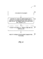
- FIG. 4 is a flowchart illustrating an example process of thermal imaging, according to one embodiment.
- heater 112 heats a surface of the object under test.
- the heater 112 may directly heat the surface by "illuminating" the surface by infrared energy using, for example, a high intensity discharge tube flash, or a continuous heat wave.
- the heater 112 may indirectly heat the surface by subjecting other parts of the object under test to energy, thus causing heating of the surface.
- Such indirect heating may be effected using, for example, inductive heating, or ultrasonic vibration heating.
- inductive heating or ultrasonic vibration heating.
- ultrasonic vibration heating the heating is discontinued after the surface reaches a predefined temperature.
- the IR imaging device 102 captures a plurality of thermal images of the surface over a period of time.
- the IR imaging device 102 being triggered by the variable time base generator 108, captures the plurality of thermal images of the surface at non-linear intervals of time. Further, each of the thermal images is associated with temporal data generated by the time module 110.
- the plurality of thermal images and the associated temporal data may be stored in the frame buffer 104.
- the image processor 114 processes the plurality of thermal images and the temporal data.
- the image processor 114 determines the contrast of each pixel by subtracting a mean intensity of all pixels of that thermal image from the pixel intensity at that point of time. The contrast is then plotted versus time for each pixel, using the temporal data associated with the thermal images.
- the image processor 114 identifies features within the object, based on the processing.
- the image processor 114 may estimate a depth of the feature based on the temporal data associated with a peak of the contrast plot. Such identification is particularly useful where the feature's thickness does not force the heat to flow around the feature (also known as a "through heat" feature).
- the processor 114 computes, at step 406, the time derivative of the contrast plot to determine the time derivative peak of contrast. Subsequently, at step 408, the processor 114 may identify the depth of the "lateral heat" feature based on the temporal data associated with the time derivative peak of contrast.
Landscapes
- Health & Medical Sciences (AREA)
- Immunology (AREA)
- Physics & Mathematics (AREA)
- Chemical & Material Sciences (AREA)
- Analytical Chemistry (AREA)
- Biochemistry (AREA)
- General Health & Medical Sciences (AREA)
- Life Sciences & Earth Sciences (AREA)
- Pathology (AREA)
- General Physics & Mathematics (AREA)
- Toxicology (AREA)
- Engineering & Computer Science (AREA)
- Multimedia (AREA)
- Signal Processing (AREA)
- Radiation Pyrometers (AREA)
- Investigating Or Analyzing Materials Using Thermal Means (AREA)
Abstract
A system (100) for thermographic imaging is described. The system (100) comprises an infra-red imaging device (102) that captures a plurality of thermal images of a surface of an object. A variable time base generator (108) triggers the infra-red imaging device (102) and a time module (110) associates temporal data with each of the plurality of thermal images.
Description
- Embodiments presented herein relate generally to infra-red imaging, and more specifically to transient thermographic inspection.
- Thermographic inspection is the nondestructive testing of objects through imaging of thermal patterns on the object's surface. Thermographic inspection is often preferred to other nondestructive testing techniques such as ultrasonic inspection and radiographic inspection, for various advantages offered by thermographic inspection. Thermographic inspection is non-contact, non-intrusive, allows for detection of subsurface detects close to the surface, allows for inspection of large surfaces, and offers high speed inspection. One form of thermographic inspection is transient thermography. Transient thermography involves observing the temperature distribution on the surface of an object under test as it is subjected to a thermal transient such as a pulse of heat or a pulse of heat sink, and then allowed to return to ambient temperature. Any flaws present are detected as abnormalities in the surface temperature distribution during this thermal transient. Transient thermography is particularly well suited to the inspection of composite materials. The relatively low thermal conductivity of composite materials results in relatively long-lived thermal transients, therefore making the thermal transient easy to detect with a thermal camera.
- Some known thermographic inspection techniques are operator dependent techniques, involving an operator to watch a thermal video of the object under test. The operator then observes the video for changes in contrast caused due to flaws within the object. Such techniques are skill intensive and require much manual effort. Automated thermographic inspection techniques also exist. Automated thermographic inspection uses a heat source such as a high intensity flash lamp to heat the surface of an object under test. An infra-red camera then takes a series of thermal images or thermograms of the object under test. The images are then post processed to identify features in the object under test.
- Known automated thermographic inspection techniques use an infra-red camera driven at a constant frame rate. In other words, the infra-red camera is adapted to capture thermal images at fixed intervals of time. However, the thermal activity occurs at a non-linear rate. This causes too few thermal images being captured at the beginning of the thermal transient, when the thermal activity is high, and too many thermal images (with a large proportion being redundant images) being captured at the end of the thermal transient when the thermal activity is significantly slower. This causes very large data files that require a large buffer memory, a faster bus, and subsequently requires large disk space for storage and archival. These higher computing requirements increase the cost of the thermographic inspection system. Some techniques may partly address the storage problem by extracting thermal images from the large set of captured images. However, such techniques still require large buffers and fast busses to facilitate high speed image capture.
- Therefore, there is a need for a thermographic inspection system that addresses these and other shortcomings associated with known solutions.
- The invention resides in a method for thermographic imaging. The method captures a plurality of thermal images of a surface of an object at non-linear intervals over a period of time, each of the thermal images being associated with temporal data. The method further includes processing the plurality of thermal images and the temporal data, and identifying features within the object based on the processing.
- The invention also resides in a system for thermographic imaging including an infrared imaging device that captures a plurality of thermal images of a surface of an object. The system further includes a variable time base generator that triggers the infra-red imaging device at non-linear intervals over a period of time. The system further includes a time module that associates temporal data with each of the plurality of thermal images. In some embodiments, the system may also include a processor for processing the plurality of thermal images taking into account the temporal data associated with each of the plurality of thermal images, and identifying features within the object. In some further embodiments, the system may also include a heater for heating the surface of the object.
- Embodiments of the present invention will now be described, by way of example only, with reference to the accompanying drawings in which:
-
FIG. 1 is a simplified block diagram of an example thermographic inspection system, according to one embodiment; -
FIG. 2 is an example time-base function used for the thermographic inspection system, according to one embodiment; -
FIG. 3 is an example time-base function used for the thermographic inspection system, according to another embodiment; and -
FIG. 4 is a flowchart of an example process of thermographic analysis, according to one embodiment. - Embodiments of a thermographic imaging system are presented herein. The system employs a non-linear time base for triggering an infra red (IR) camera, to enable imaging at a non-linear rate. In transient thermographic testing, for example, the object under test is heated by a predefined temperature. Heating is then stopped and the object under test allowed to return to ambient temperature. During the thermal transient, thermal activity of the object under test takes place at a non-linear rate dependant on various factors such as, but not limited to, emissivity, absorptivity, reflectivity, and temperature of the object under test. Specifically, the thermal activity occurs rapidly at the beginning of the thermal transient, and slows down as the thermal transient progresses. Thus, imaging at the non-linear rate may reduce the number of redundant images, thus reducing requirements of processing power, buffer memory, and image file sizes. The system stores temporal data associated with each of the captured images for further processing. In some embodiments, the system also includes a processing module for detecting and identifying features in an object under test.
-
FIG. 1 illustrates a simplified block diagram of an examplethermographic imaging system 100, according to various embodiments. Thethermographic imaging system 100 includes anIR imaging device 102, aframe buffer 104, and acontrol module 106. Thecontrol module 106 further includes a variabletime base generator 108, and atime module 110. Thethermographic imaging system 100 may include aheater 112, and animage processor 114. However, theheater 112, and theimage processor 114 may be part of other equipment used for thermographic inspection and analysis. Theheater 112 may include a high intensity discharge tube flash unit, a continuous infrared lamp, an induction heating unit, an ultrasonic vibration heater, or the like. - The
IR imaging device 102 may include an IR sensor such as, but not limited to, a focal plane array IR sensor. The IR sensor may be, for example, a vanadium oxide microbolometer array. It should be appreciated that other IR sensors may also be used. TheIR imaging device 102 may further include one or more IR lenses to produce a sharp image on the IR sensor. The IR lens may be designed to pass only light in the infra red spectrum. - The
frame buffer 104 temporarily stores the thermal images captured by theIR imaging device 102, until the thermal images can be transferred to a non-volatile storage device, or transmitted over a network to an image processing terminal. Theframe buffer 104 may be a high speed semiconductor memory device. - The
control module 106 controls the operation of theIR imaging device 102, and theframe buffer 104. Thecontrol module 106 includes the variabletime base generator 108, and thetime module 110. The variabletime base generator 108 generates a non-linear time base signal for triggering theIR imaging device 102. The non-linear time base signal triggers theIR imaging device 102 at non-linear intervals of time. In other words, the variabletime base generator 108 causes the frame rate of theIR imaging device 102 to change over time. In various implementations, the variabletime base generator 108 triggers theIR imaging device 102 after short time intervals at the beginning of a thermal transient, where a noticeable difference in thermal activity occurs in a short time interval. As the thermal transient progresses, the variabletime base generator 108 triggers theIR imaging device 102 after longer time intervals, since a difference in thermal activity may only be noticed at much longer time intervals. Thus, the use of a non-linear time base signal enables capturing an optimal number of thermal images and reducing the number of redundant thermal images. - The variable
time base generator 108 may generate a continuously varying time base signal to trigger theIR imaging device 102.FIG. 2 illustrates an example time base signal that varies continuously with time. Alternatively, the variabletime base generator 108 may generate a discretely varying time base signal, such as a step function of time.FIG. 3 illustrates an example time base signal that varies as a step function of time. In one implementation, the time base function of the variabletime base generator 108 may be designed to complement the rate of thermal activity. In another implementation, the time base function of the variabletime base generator 108 may be designed to complement an image processing operation of theimage processor 114. For instance, the time base function may be designed to complement a Gaussian function for temporal smoothing of the series of captured thermal images. - The variable
time base generator 108 may be implemented as an analog circuit using, for example, square law devices such as MOSFETs operating in the saturation region, capacitors for exponential time base, operational amplifiers and so forth. Alternatively, the variabletime base generator 108 may be implemented as a digital circuit using, for example, a microprocessor, a programmable logic device such as a field programmable gate array, and so forth. In one example implementation, a microprocessor may be programmed with a time base computing function, to generate the variable time base signal. - In some low complexity thermal imaging systems, the variable
time base generator 108 may be hardcoded or hardwired into thethermal imaging system 100. Such an implementation may be suitable for low cost thermal imaging systems and portable thermal imaging systems. Alternatively, the variabletime base generator 108 may be a programmable or configurable time base generator. One example implementation of a programmable variable time base generator may accept user input of a time base function. In another example implementation, the programmable variable time base generator may have stored thereon in a memory, a plurality of time base functions. The programmable variable time base generator may accept user selection of one of the plurality of time base functions. Each of the plurality of time base functions may be associated with a specific type of object to be tested, or for specific materials, or for specific physical dimensions. Such a system may accept inputs to select the specific type of object to be tested, or the specific material, or the specific physical dimensions, or a combination thereof, and select a suitable time base function based on the input. - The
control module 106 also includes atime module 110. Thetime module 110 generates temporal data for each of the captured thermal images. The temporal data may be an accurate time stamp precise to a millisecond, for example. The temporal data may then be used for processing the thermal images. In one implementation, thetime module 110 stores the generated temporal data in theframe buffer 104, in association with the appropriate thermal image. Thecontrol module 106 may be configured to precisely synchronize the transfer of the thermal image captured by theIR imaging device 102 into theframe buffer 104, with the transfer of the temporal data from thetime stamping module 110 to theframe buffer 104. - The
image processor 114 then processes the thermal images stored in theframe buffer 104 to identify features within the object under test. Theimage processor 114 may use any suitable algorithm for processing the thermal images. However, theimage processor 114 may now directly use the temporal data associated the thermal images to identify features, instead of the conventional technique of using frame numbers translated into an estimated time of thermal image capture. -
FIG. 4 is a flowchart illustrating an example process of thermal imaging, according to one embodiment. Atstep 402,heater 112 heats a surface of the object under test. Theheater 112 may directly heat the surface by "illuminating" the surface by infrared energy using, for example, a high intensity discharge tube flash, or a continuous heat wave. Alternatively, theheater 112 may indirectly heat the surface by subjecting other parts of the object under test to energy, thus causing heating of the surface. - Such indirect heating may be effected using, for example, inductive heating, or ultrasonic vibration heating. In case of transient thermography, the heating is discontinued after the surface reaches a predefined temperature.
- At
step 404, theIR imaging device 102 captures a plurality of thermal images of the surface over a period of time. TheIR imaging device 102 being triggered by the variabletime base generator 108, captures the plurality of thermal images of the surface at non-linear intervals of time. Further, each of the thermal images is associated with temporal data generated by thetime module 110. The plurality of thermal images and the associated temporal data may be stored in theframe buffer 104. - At
step 406, theimage processor 114 processes the plurality of thermal images and the temporal data. In one example implementation, theimage processor 114 determines the contrast of each pixel by subtracting a mean intensity of all pixels of that thermal image from the pixel intensity at that point of time. The contrast is then plotted versus time for each pixel, using the temporal data associated with the thermal images. - At
step 408, theimage processor 114 identifies features within the object, based on the processing. Theimage processor 114 may estimate a depth of the feature based on the temporal data associated with a peak of the contrast plot. Such identification is particularly useful where the feature's thickness does not force the heat to flow around the feature (also known as a "through heat" feature). - However, when the rate of diffusion of the heat is faster around the feature than through the feature (also known as a "lateral heat" feature), the contrast peak is not evident from the contrast plot. In such a case, the
processor 114 computes, atstep 406, the time derivative of the contrast plot to determine the time derivative peak of contrast. Subsequently, atstep 408, theprocessor 114 may identify the depth of the "lateral heat" feature based on the temporal data associated with the time derivative peak of contrast. - Although specific implementations have been described in the embodiments presented herein, such implementations are exemplary, and should not be considered limiting in scope. Other variations of the implementations are also envisioned and the scope is defined by the appended claims.
Claims (17)
- A method comprising:capturing (404) a plurality of thermal images of a surface of an object at non-linear intervals over a period of time, each of the thermal images being associated with temporal data;processing (406) the plurality of thermal images and the temporal data; and identifying (408) features within the object based on the processing.
- The method of claim 1, wherein the non-linear intervals are a step function of time.
- The method of claim 1, wherein the non-linear intervals are a square law function of time.
- The method of claim 1, wherein the non-linear intervals are defined based on a function of thermal emissivity of a material of the object.
- The method of claim 1, wherein the non-linear intervals are defined based on an image processing function used in the processing of the plurality of thermal images.
- A system (100) comprising:an infra-red imaging device (102) that captures a plurality of thermal images of a surface of an object;a variable time base generator (108) that triggers the infra-red imaging device (102) at non-linear intervals over a period of time; anda time module (110) that associates temporal data with each of the plurality of thermal images.
- The system of claim 6, further comprising a processor (114) that processes the plurality of thermal images taking into account the temporal data of each of the plurality of thermal images, and identifying features within the object.
- The system of claim 6 or 7, further comprising a heater (112) that heats the surface of the object.
- The system of claim 8, wherein the heater (112) includes one of a flash lamp, a quartz lamp, a microwave tube, or a laser source.
- The system of any of claims 6 to 9, wherein the variable time base generator (108) includes a step function generator.
- The system of any of claims 6 to 9, wherein the variable time base generator (108) includes a square law function generator.
- The system of any of claims 6 to 9, wherein the variable time base generator (108) includes a programmable function generator comprising:an input that accepts a material selection;a memory unit that stores a plurality of time base functions, each of the plurality of time base functions corresponding to thermal emissivity of a specific material; anda selector that selects an appropriate one of the plurality of time base functions based on the input.
- The system of any of claims 6 to 12, wherein the variable time base generator (108) comprises a hard wired function generator.
- The system of any of claims 6 to 13, wherein the infra-red imaging device (102) includes a focal plane array sensor.
- The system of claim 6, wherein the time module (110) associates a time stamp with each of the plurality of thermal images.
- A computer program comprising computer program code means arranged to perform the steps of the method of any of claims 1 to 5.
- The computer program of claim 16, embodied on a computer readable medium.
Applications Claiming Priority (1)
| Application Number | Priority Date | Filing Date | Title |
|---|---|---|---|
| US13/094,921 US9007466B2 (en) | 2011-04-27 | 2011-04-27 | System and method for thermographic inspection |
Publications (1)
| Publication Number | Publication Date |
|---|---|
| EP2518480A1 true EP2518480A1 (en) | 2012-10-31 |
Family
ID=46298225
Family Applications (1)
| Application Number | Title | Priority Date | Filing Date |
|---|---|---|---|
| EP12165067A Withdrawn EP2518480A1 (en) | 2011-04-27 | 2012-04-20 | System and method for thermographic inspection |
Country Status (3)
| Country | Link |
|---|---|
| US (1) | US9007466B2 (en) |
| EP (1) | EP2518480A1 (en) |
| CN (1) | CN102778477B (en) |
Cited By (4)
| Publication number | Priority date | Publication date | Assignee | Title |
|---|---|---|---|---|
| EP2975396A1 (en) * | 2014-07-17 | 2016-01-20 | The Boeing Company | Nondestructive inspection using ultrasound |
| EP3312009A1 (en) * | 2016-10-18 | 2018-04-25 | General Electric Company | Method and system for thermographic inspection of additive manufactured parts |
| FR3071611A1 (en) * | 2017-09-28 | 2019-03-29 | Safran | METHOD AND DEVICE FOR NON-DESTRUCTIVE CONTROL OF AN AERONAUTICAL WORKPIECE |
| EP3564659A1 (en) * | 2018-04-11 | 2019-11-06 | General Electric Company | Cooling hole inspection system |
Families Citing this family (10)
| Publication number | Priority date | Publication date | Assignee | Title |
|---|---|---|---|---|
| US9324138B2 (en) * | 2013-03-15 | 2016-04-26 | Eric Olsen | Global contrast correction |
| CN103245668B (en) * | 2013-04-22 | 2015-03-25 | 南京诺威尔光电系统有限公司 | Laser scanning thermal wave imaging method |
| US9878804B2 (en) | 2013-10-21 | 2018-01-30 | Eric Olsen | Systems and methods for producing temperature accurate thermal images |
| US9347899B2 (en) | 2013-12-06 | 2016-05-24 | Rolls-Royce Corporation | Thermographic inspection techniques |
| CN104677944B (en) * | 2015-03-25 | 2018-04-17 | 何赟泽 | A kind of microwave frequency modulation thermal wave imaging system and method |
| US10033910B2 (en) | 2016-04-15 | 2018-07-24 | General Electric Company | Synchronous sampling methods for infrared cameras |
| US10473603B2 (en) * | 2017-04-18 | 2019-11-12 | Saudi Arabian Oil Company | Apparatus, system and method for inspecting composite structures using quantitative infra-red thermography |
| CN107782786B (en) * | 2017-09-27 | 2024-05-28 | 重庆交通大学 | Steel structure corrosion detection device and method based on pulse microwave heating vibration measurement |
| CN109900742B (en) * | 2019-04-03 | 2019-12-17 | 哈尔滨商业大学 | A device and method for detecting debonding defects of carbon fiber composite materials with linear and nonlinear frequency modulation hybrid excitation refrigeration |
| US11492913B2 (en) * | 2020-07-21 | 2022-11-08 | General Electric Company | Cooling hole inspection system |
Citations (7)
| Publication number | Priority date | Publication date | Assignee | Title |
|---|---|---|---|---|
| WO2000063642A1 (en) * | 1999-04-16 | 2000-10-26 | General Electric Company | Transient thermography measurement of a metal layer thickness |
| WO2001041421A2 (en) * | 1999-12-02 | 2001-06-07 | Thermal Wave Imaging, Inc. | Method and system for reference-free thermographic detection of subsurface defects using compressed image data |
| US20040041096A1 (en) * | 2002-08-30 | 2004-03-04 | The University Of Chicago | Method and apparatus for detecting normal cracks using infrared thermal imaging |
| US7365330B1 (en) * | 2006-09-18 | 2008-04-29 | Uchicago Argonne, Llc | Method for thermal tomography of thermal effusivity from pulsed thermal imaging |
| EP1918698A1 (en) * | 2006-11-03 | 2008-05-07 | General Electric Company | Systems and method for locating failure events in samples under load |
| US7408156B2 (en) * | 1999-06-21 | 2008-08-05 | Yannacone Jr Victor John | System and method for identifying and classifying dynamic thermodynamic processes in mammals and discriminating between and among such processes |
| US7966883B2 (en) * | 2006-12-06 | 2011-06-28 | Lockheed Martin Corporation | Non-destructive inspection using laser-ultrasound and infrared thermography |
Family Cites Families (13)
| Publication number | Priority date | Publication date | Assignee | Title |
|---|---|---|---|---|
| US5711603A (en) | 1996-10-30 | 1998-01-27 | United Technologies Corporation | Nondestructive testing: transient depth thermography |
| US6065072A (en) * | 1997-05-29 | 2000-05-16 | Thermal Wave Imaging, Inc. | Device for selectively passing video frames from a signal series having a first frame rate to obtain a signal series having a second frame rate |
| US6367969B1 (en) * | 1999-07-21 | 2002-04-09 | General Electric Company | Synthetic reference thermal imaging method |
| US6367968B1 (en) * | 1999-07-21 | 2002-04-09 | General Electric Company | Thermal resonance imaging method |
| US7724925B2 (en) * | 1999-12-02 | 2010-05-25 | Thermal Wave Imaging, Inc. | System for generating thermographic images using thermographic signal reconstruction |
| WO2003062809A1 (en) * | 2002-01-23 | 2003-07-31 | Marena Systems Corporation | Infrared thermography for defect detection and analysis |
| JP4495154B2 (en) * | 2003-05-06 | 2010-06-30 | ビクター ジョン ジュニア ヤナコーネ | A system to identify and classify and identify dynamic thermodynamic processes in mammals |
| WO2006023212A2 (en) * | 2004-07-26 | 2006-03-02 | Thermal Wave Imaging | Infrared camera measurement correction for pulsed excitation with subframe duration |
| JP4146407B2 (en) * | 2004-09-03 | 2008-09-10 | エスアイアイ・ナノテクノロジー株式会社 | Thermal analyzer |
| US7687176B2 (en) * | 2004-12-10 | 2010-03-30 | 3M Innovative Properties Company | Fuel cell |
| US7822268B2 (en) | 2006-06-06 | 2010-10-26 | Siemens Energy, Inc. | Advanced processing of active thermography signals |
| WO2011059127A1 (en) * | 2009-11-13 | 2011-05-19 | 한국과학기술연구원 | Infrared sensor and sensing method using the same |
| US8374821B2 (en) * | 2010-12-22 | 2013-02-12 | Utility Risk Management Corporation, Llc | Thermal powerline rating and clearance analysis using thermal imaging technology |
-
2011
- 2011-04-27 US US13/094,921 patent/US9007466B2/en not_active Expired - Fee Related
-
2012
- 2012-04-20 EP EP12165067A patent/EP2518480A1/en not_active Withdrawn
- 2012-04-27 CN CN201210143306.3A patent/CN102778477B/en not_active Expired - Fee Related
Patent Citations (7)
| Publication number | Priority date | Publication date | Assignee | Title |
|---|---|---|---|---|
| WO2000063642A1 (en) * | 1999-04-16 | 2000-10-26 | General Electric Company | Transient thermography measurement of a metal layer thickness |
| US7408156B2 (en) * | 1999-06-21 | 2008-08-05 | Yannacone Jr Victor John | System and method for identifying and classifying dynamic thermodynamic processes in mammals and discriminating between and among such processes |
| WO2001041421A2 (en) * | 1999-12-02 | 2001-06-07 | Thermal Wave Imaging, Inc. | Method and system for reference-free thermographic detection of subsurface defects using compressed image data |
| US20040041096A1 (en) * | 2002-08-30 | 2004-03-04 | The University Of Chicago | Method and apparatus for detecting normal cracks using infrared thermal imaging |
| US7365330B1 (en) * | 2006-09-18 | 2008-04-29 | Uchicago Argonne, Llc | Method for thermal tomography of thermal effusivity from pulsed thermal imaging |
| EP1918698A1 (en) * | 2006-11-03 | 2008-05-07 | General Electric Company | Systems and method for locating failure events in samples under load |
| US7966883B2 (en) * | 2006-12-06 | 2011-06-28 | Lockheed Martin Corporation | Non-destructive inspection using laser-ultrasound and infrared thermography |
Cited By (6)
| Publication number | Priority date | Publication date | Assignee | Title |
|---|---|---|---|---|
| EP2975396A1 (en) * | 2014-07-17 | 2016-01-20 | The Boeing Company | Nondestructive inspection using ultrasound |
| US9360418B2 (en) | 2014-07-17 | 2016-06-07 | The Boeing Company | Nondestructive inspection using hypersound |
| EP3312009A1 (en) * | 2016-10-18 | 2018-04-25 | General Electric Company | Method and system for thermographic inspection of additive manufactured parts |
| FR3071611A1 (en) * | 2017-09-28 | 2019-03-29 | Safran | METHOD AND DEVICE FOR NON-DESTRUCTIVE CONTROL OF AN AERONAUTICAL WORKPIECE |
| EP3564659A1 (en) * | 2018-04-11 | 2019-11-06 | General Electric Company | Cooling hole inspection system |
| US10551327B2 (en) | 2018-04-11 | 2020-02-04 | General Electric Company | Cooling hole inspection system |
Also Published As
| Publication number | Publication date |
|---|---|
| US9007466B2 (en) | 2015-04-14 |
| CN102778477B (en) | 2016-12-14 |
| CN102778477A (en) | 2012-11-14 |
| US20120274778A1 (en) | 2012-11-01 |
Similar Documents
| Publication | Publication Date | Title |
|---|---|---|
| US9007466B2 (en) | System and method for thermographic inspection | |
| CN103674839B (en) | A kind of visual Sample location operating system based on spot detection and method | |
| EP3312763B1 (en) | Method, apparatus, and mobile terminal for determining foreign material on surface of fingerprint sensor | |
| CN105096514B (en) | An intelligent fire alarm method based on infrared camera temperature process monitoring | |
| KR101546933B1 (en) | Apparatus for sensing fire | |
| WO2007147158A2 (en) | Infrared defect detection system and method for the evaluation of powdermetallic compacts | |
| Runnemalm et al. | Automatic inspection of spot welds by thermography | |
| US20100118137A1 (en) | Gradient image processing | |
| JP2016501376A (en) | Sample inspection method and system using thermography | |
| WO2016203078A3 (en) | Ir or thermal image enhancement method based on background information for video analysis | |
| WO2016165379A1 (en) | Projection method, device, apparatus and computer storage medium | |
| CN111707381A (en) | A temperature deformation synchronous measurement system and method based on sub-channel photosensitive | |
| CN119197318B (en) | Battery cell detection method, electronic equipment and detection system | |
| EP3128323A1 (en) | Method and system for detecting defects in plastic containers | |
| US20200059624A1 (en) | Gas Detection Device, Information Processing Device, And Program | |
| KR101625471B1 (en) | Method and apparatus for enhancing resolution of popular low cost thermal image camera | |
| CN120629159A (en) | A method and system for identifying hot pressing defects of plastic honeycomb panels | |
| US10504236B2 (en) | Testing a battery | |
| JP2021000275A5 (en) | ||
| CN108076655B (en) | Focus detection method, device, storage medium and equipment for substance detection | |
| JP6568691B2 (en) | Flaw detection system and flaw detection method for detecting internal defect of flaw detection object | |
| JP2015187832A5 (en) | ||
| RU2509300C1 (en) | Method for active single-sided thermal control of hidden defects in solid bodies | |
| JP2019179488A (en) | Information processing device, information processing system, control method, and program | |
| JP2004282299A (en) | Infrared camera |
Legal Events
| Date | Code | Title | Description |
|---|---|---|---|
| PUAI | Public reference made under article 153(3) epc to a published international application that has entered the european phase |
Free format text: ORIGINAL CODE: 0009012 |
|
| AK | Designated contracting states |
Kind code of ref document: A1 Designated state(s): AL AT BE BG CH CY CZ DE DK EE ES FI FR GB GR HR HU IE IS IT LI LT LU LV MC MK MT NL NO PL PT RO RS SE SI SK SM TR |
|
| AX | Request for extension of the european patent |
Extension state: BA ME |
|
| 17P | Request for examination filed |
Effective date: 20130117 |
|
| 17Q | First examination report despatched |
Effective date: 20140728 |
|
| STAA | Information on the status of an ep patent application or granted ep patent |
Free format text: STATUS: THE APPLICATION IS DEEMED TO BE WITHDRAWN |
|
| 18D | Application deemed to be withdrawn |
Effective date: 20141209 |