EP2518420A1 - Photovoltaic energy harvesting system with flexible support - Google Patents
Photovoltaic energy harvesting system with flexible support Download PDFInfo
- Publication number
- EP2518420A1 EP2518420A1 EP11163913A EP11163913A EP2518420A1 EP 2518420 A1 EP2518420 A1 EP 2518420A1 EP 11163913 A EP11163913 A EP 11163913A EP 11163913 A EP11163913 A EP 11163913A EP 2518420 A1 EP2518420 A1 EP 2518420A1
- Authority
- EP
- European Patent Office
- Prior art keywords
- flexible
- photovoltaic
- driving means
- fixtures
- support
- Prior art date
- Legal status (The legal status is an assumption and is not a legal conclusion. Google has not performed a legal analysis and makes no representation as to the accuracy of the status listed.)
- Withdrawn
Links
Images

Classifications
-
- H—ELECTRICITY
- H02—GENERATION; CONVERSION OR DISTRIBUTION OF ELECTRIC POWER
- H02S—GENERATION OF ELECTRIC POWER BY CONVERSION OF INFRARED RADIATION, VISIBLE LIGHT OR ULTRAVIOLET LIGHT, e.g. USING PHOTOVOLTAIC [PV] MODULES
- H02S20/00—Supporting structures for PV modules
-
- F—MECHANICAL ENGINEERING; LIGHTING; HEATING; WEAPONS; BLASTING
- F24—HEATING; RANGES; VENTILATING
- F24S—SOLAR HEAT COLLECTORS; SOLAR HEAT SYSTEMS
- F24S25/00—Arrangement of stationary mountings or supports for solar heat collector modules
- F24S25/10—Arrangement of stationary mountings or supports for solar heat collector modules extending in directions away from a supporting surface
- F24S25/13—Profile arrangements, e.g. trusses
-
- F—MECHANICAL ENGINEERING; LIGHTING; HEATING; WEAPONS; BLASTING
- F24—HEATING; RANGES; VENTILATING
- F24S—SOLAR HEAT COLLECTORS; SOLAR HEAT SYSTEMS
- F24S30/00—Arrangements for moving or orienting solar heat collector modules
- F24S30/40—Arrangements for moving or orienting solar heat collector modules for rotary movement
- F24S30/45—Arrangements for moving or orienting solar heat collector modules for rotary movement with two rotation axes
-
- F—MECHANICAL ENGINEERING; LIGHTING; HEATING; WEAPONS; BLASTING
- F24—HEATING; RANGES; VENTILATING
- F24S—SOLAR HEAT COLLECTORS; SOLAR HEAT SYSTEMS
- F24S30/00—Arrangements for moving or orienting solar heat collector modules
- F24S30/40—Arrangements for moving or orienting solar heat collector modules for rotary movement
- F24S30/48—Arrangements for moving or orienting solar heat collector modules for rotary movement with three or more rotation axes or with multiple degrees of freedom
-
- H—ELECTRICITY
- H02—GENERATION; CONVERSION OR DISTRIBUTION OF ELECTRIC POWER
- H02S—GENERATION OF ELECTRIC POWER BY CONVERSION OF INFRARED RADIATION, VISIBLE LIGHT OR ULTRAVIOLET LIGHT, e.g. USING PHOTOVOLTAIC [PV] MODULES
- H02S20/00—Supporting structures for PV modules
- H02S20/10—Supporting structures directly fixed to the ground
-
- F—MECHANICAL ENGINEERING; LIGHTING; HEATING; WEAPONS; BLASTING
- F24—HEATING; RANGES; VENTILATING
- F24S—SOLAR HEAT COLLECTORS; SOLAR HEAT SYSTEMS
- F24S30/00—Arrangements for moving or orienting solar heat collector modules
- F24S2030/10—Special components
- F24S2030/13—Transmissions
- F24S2030/136—Transmissions for moving several solar collectors by common transmission elements
-
- Y—GENERAL TAGGING OF NEW TECHNOLOGICAL DEVELOPMENTS; GENERAL TAGGING OF CROSS-SECTIONAL TECHNOLOGIES SPANNING OVER SEVERAL SECTIONS OF THE IPC; TECHNICAL SUBJECTS COVERED BY FORMER USPC CROSS-REFERENCE ART COLLECTIONS [XRACs] AND DIGESTS
- Y02—TECHNOLOGIES OR APPLICATIONS FOR MITIGATION OR ADAPTATION AGAINST CLIMATE CHANGE
- Y02B—CLIMATE CHANGE MITIGATION TECHNOLOGIES RELATED TO BUILDINGS, e.g. HOUSING, HOUSE APPLIANCES OR RELATED END-USER APPLICATIONS
- Y02B10/00—Integration of renewable energy sources in buildings
- Y02B10/20—Solar thermal
-
- Y—GENERAL TAGGING OF NEW TECHNOLOGICAL DEVELOPMENTS; GENERAL TAGGING OF CROSS-SECTIONAL TECHNOLOGIES SPANNING OVER SEVERAL SECTIONS OF THE IPC; TECHNICAL SUBJECTS COVERED BY FORMER USPC CROSS-REFERENCE ART COLLECTIONS [XRACs] AND DIGESTS
- Y02—TECHNOLOGIES OR APPLICATIONS FOR MITIGATION OR ADAPTATION AGAINST CLIMATE CHANGE
- Y02E—REDUCTION OF GREENHOUSE GAS [GHG] EMISSIONS, RELATED TO ENERGY GENERATION, TRANSMISSION OR DISTRIBUTION
- Y02E10/00—Energy generation through renewable energy sources
- Y02E10/40—Solar thermal energy, e.g. solar towers
- Y02E10/47—Mountings or tracking
-
- Y—GENERAL TAGGING OF NEW TECHNOLOGICAL DEVELOPMENTS; GENERAL TAGGING OF CROSS-SECTIONAL TECHNOLOGIES SPANNING OVER SEVERAL SECTIONS OF THE IPC; TECHNICAL SUBJECTS COVERED BY FORMER USPC CROSS-REFERENCE ART COLLECTIONS [XRACs] AND DIGESTS
- Y02—TECHNOLOGIES OR APPLICATIONS FOR MITIGATION OR ADAPTATION AGAINST CLIMATE CHANGE
- Y02E—REDUCTION OF GREENHOUSE GAS [GHG] EMISSIONS, RELATED TO ENERGY GENERATION, TRANSMISSION OR DISTRIBUTION
- Y02E10/00—Energy generation through renewable energy sources
- Y02E10/50—Photovoltaic [PV] energy
Definitions
- the present invention relates to the field of photovoltaic energy generation, more specifically, it relates to systems for photovoltaic energy harvesting with active solar tracking.
- Photovoltaic generators are commonly used to receive solar rays and convert them into electricity for being provided to an electrical load.
- Such photovoltaic generators typically comprise photovoltaic panels, which for example encase multiple photovoltaic cells between glass layers.
- the photovoltaic cells have an active surface, responsible for converting solar rays into electrical currents.
- the low efficiency of photovoltaic generators also entails a large exposure surface area requirement as function of energy production. For example, a system required to have a peak output power of 10 kW may require a surface area of about 150 m 2 .
- photovoltaic panels may be placed on support structures adapted for the purpose of photovoltaic energy generation.
- support structures may furthermore provide additional advantages.
- a shelter structure for vehicles comprises a support which supports photovoltaic panels.
- the support is furthermore adapted to allow rotation and inclination of the photovoltaic panels, such that the photovoltaic cells may be oriented to optimize power output.
- the disclosed shelter structure thus combines photovoltaic energy collection with the added benefit of providing a shelter for vehicles, and provides sun-tracking capabilities to optimize yield.
- the present invention provides a photovoltaic energy harvesting system comprising a support, said support having a carrier structure with a base and flexible fixtures attached to said base, and a plurality of photovoltaic receptors, said photovoltaic receptors being attached to the flexible fixtures.
- the flexible fixtures are adapted for providing flexural integrity to the support.
- flexural integrity refers specifically to the use of potential energy stored in a deformed object, e.g.
- the photovoltaic energy harvesting system furthermore comprises a flexible fixture spacer element having at least three points of force application, and at least two driving means for exerting forces on at least two of the points of force application such that the direction of each of said photovoltaic receptors is collectively orientable through the action of said driving means.
- a photovoltaic energy harvesting system according to embodiments of the present invention that energy harvesting is efficient, due to the orientability of photovoltaic receptors.
- the system according to embodiments of the present invention is particularly advantageous as it provides a simple and easily operable means for providing the collective orientability of the photovoltaic receptors.
- a system according to embodiments of the present invention may furthermore comprise, on top of the at least two driving means for exerting forces on at least two of the points of force application, at least one rigid linkage connecting at least one of the points of force application to the base of said support.
- a system according to embodiments of the present invention may comprise three driving means for exerting force on three points of force application on the flexible fixture spacer element. This later embodiment provides the advantageous possibility to constrict the complete structure so as to decrease its flexibility increase its rigidity, which may prove particularly useful for example in case of windy conditions, for example in case of storm.
- the flexible fixture spacer element may be contacting said flexible fixtures.
- different degrees of intensity of contact are possible.
- contact may be obtained because the spacer element is pressed against the flexible fixtures or vice versa, thus providing a sliding contact.
- such sliding contact can be limited to a sliding contact in one direction, e.g. by guiding the flexible fixtures through a sliding bush.
- a hinging contact may be provided between the spacer element and the flexible fixtures.
- the at least two, optionally three or more driving means may directly exert force on an equal number of points of force application, for example by means of a plunjer-cylinder system directly impacting on the flexible fixture spacer element.
- a system according to embodiments of the present invention may comprise at least one tensioning element adapted for transmission of mechanical force from at least one of said driving means to at least one of said points of force application.
- a same number of tensioning elements may be provided as the number of driving means present.
- each driving means impacts on the flexible fixture spacer element via a tensioning element.
- the driving means may be linear actuators.
- the at least one tensioning element may be a wire element, which is optionally at least partly lead through a casing.
- the at least one tensioning element may be a push-pull cable, at least partly guided through a flexible casing.
- the flexible fixtures may be formed in a loop.
- the flexible fixtures may comprise at least one resilient lineal element, which may for example comprise glass fiber, steel or a composite material.
- the flexible fixtures may comprise two or more resilient lineal elements forming the loop.
- a plurality of connections may be provided between said plurality of loops for providing flexural integrity to the support. These contacts may be sliding contacts.
- the flexible fixtures may comprise electrical conductors for conducting electricity generated by said photovoltaic receptors.
- the electrical conductors may guide the generated electricity towards an appliance being driven by this electricity, or towards a battery system for storing the corresponding energy.
- a system may furthermore comprise a controlling means adapted for controlling said at least two driving means.
- Said controlling means may for example be integrated in the stem of the support.
- the controlling means may be adapted for controlling the direction of the photovoltaic receptors taking into account a predetermined path of the sun on the celestial sphere.
- the controlling means may be adapted for controlling the direction of the photovoltaic receptors so as to optimize the output of said energy harvesting system.
- the controlling means may be adapted for controlling the direction of the photovoltaic receptors taking into account meteorological circumstances, in particular for example windy conditions or snow.
- a system according to embodiments of the present invention may furthermore comprise an electricity outlet for electrical and/or hybrid vehicles.
- the electricity outlet may be electrically connected to the photovoltaic receptors, such that it is the electricity generated by the photovoltaic receptors which may be used for charging electrical and/or hybrid vehicles.
- a system according to embodiments of the present invention may furthermore comprise at least one illumination source.
- This illumination source may get the required electrical input from a chargeable energy storage device, such as a rechargeable battery, a capacitor or a flywheel.
- a chargeable energy storage device may be charged with electricity generated by the photovoltaic receptors, e.g. during daylight, to provide the at least one illumination source with stored electricity under low ambient light conditions, e.g. at night.
- the present invention provides a method for harvesting photovoltaic energy, the method comprising providing tensional integrity to a support having photovoltaic receptors attached thereto, exerting a plurality of forces on a flexible fixture spacer element, such that said flexible fixture spacer element bends said support so as to collectively adjust the orientation of each of said photovoltaic receptors, and generating electricity with said photovoltaic receptors.
- Exerting a plurality of forces may include taking into account a predetermined path of the sun on the celestial sphere.
- Exerting a plurality of forces may include optimizing the output of the photovoltaic receptors.
- Exerting a plurality of forces may include taking into account meteorological circumstances.
- flexural integrity refers to the use of a material's ability to resist deformation under load so as to provide structural integrity.
- flexural integrity refers to the use of potential energy stored in a deformed object, e.g. a bended elongate object made of material with a high flexural modulus, such as for example a bended steel wire spring, such that the object can support and resist self-weight and loads it is subjected to.
- a structure exhibiting flexural integrity is assumed to form a coherent entity, i.e. to possess internal integrity.
- the present invention relates to a photovoltaic energy harvesting system.
- photovoltaic energy harvesting systems are commonly used to receive solar rays and convert them into electricity to be provided to an electrical load.
- an electrical load may for example comprise a chargeable battery, a lighting fixture, an electrical consumer appliance, an electrical or hybrid vehicle or any electrical power consuming device in general.
- Such an electrical load may also comprise a distribution infrastructure to supply energy to any number of such power consuming devices, such as a local power distribution grid of a private or public building or a large area power distribution grid.
- Such a photovoltaic energy harvesting system may comprise any number and/or combination of suitable elements for transforming, conditioning, conducting, storing and/or transmitting energy, depending on intended operational characteristics of the system, as would be evident to a person skilled in the art.
- suitable elements may for example comprise transformers, inverters, capacitors, batteries, flywheels, interconnection wiring, gauges and/or controllers.
- FIG. 1 and FIG. 2 an exemplary photovoltaic energy harvesting system 100 according to a first embodiment of the first aspect of the present invention is illustrated in FIG. 1 and FIG. 2
- FIG. 3 an exemplary photovoltaic energy harvesting system 100 according to a second embodiment of the first aspect of the present invention is illustrated in FIG. 3 , FIG. 4 and FIG. 5 .
- Both embodiments will be discussed in more detail below. They are different in the basics of the flexible fixtures 115, but they share a lot of other details.
- the photovoltaic energy harvesting system 100 comprises a support.
- This support has a carrier structure with a base 112 and flexible fixtures 115 attached to said base 112.
- the base 112 may be fixed to or into the ground by any suitable anchoring member, such as for example a plinth or any other foundation system.
- the base 112 may furthermore comprise a post 113, e.g. a post extending along a substantially vertical axis to achieve a predetermined height, for example to avoid overshadowing of the photovoltaic energy harvesting system 100 by other structures in the environment, to avoid obstruction of pedestrians and/or vehicles by the support or to reduce the risk of theft or vandalism.
- the flexible fixtures 115 are adapted for providing flexural integrity to the support.
- the flexible fixtures 115 may form for example a number of flexible leaves or leave-like structures.
- the flexible fixtures 115 form three leaves attached to the base 112 of the support.
- the leaves being only attached at one end 116 while the other end 117 may move freely, bend under the force of gravity until an equilibrium is reached between gravitational forces and the stresses in the material of the flexible fixtures 115 induced by the bending.
- the free ends 117 of the leaves may for example be interconnected by flexible bands 118, e.g.
- the flexible fixtures 115 of one leave may cross flexible fixtures 115 of another leave.
- other types of interconnections between the leaves may be provided, such as for example sliding bushes or hinging connections.
- the flexible fixtures 115 may comprise at least one resilient lineal element, such as a wire or a tubular element.
- the at least one resilient lineal element may for example consist of lengths of metal wire, e.g. wire springs composed of steel, having any appropriate cross-section, such as rectangular, oblong, elliptical or round.
- the material, e.g. metal, of which the resilient lineal element is made has a high tensile strength in order to make it less plastically deformable under flexion.
- Suitable metallic compositions are, the present invention not being limited thereto, high tensile steels, stainless steels or high carbon steels. Temperature hardened steels such as oil-hardened wires may be particularly useful.
- the wires may be coated with a functional coating, for example to protect the steel from rusting, e.g. by galvanizing the steel, to provide a sufficiently sliding contact, e.g. by means of a Teflon or PET coating, or simply for aesthetic reasons.
- a functional coating for example to protect the steel from rusting, e.g. by galvanizing the steel, to provide a sufficiently sliding contact, e.g. by means of a Teflon or PET coating, or simply for aesthetic reasons.
- a single flexible fixture 115 e.g. in the form of a single resilient lineal element 210, may be formed in a loop so as to form a leave-like structure, e.g. as shown in FIG. 5 .
- Lineal element such as metal wire may be used to form a plurality of loops, e.g. as shown in FIG. 3 and FIG. 4 , each loop forming a leave-like structure.
- Flexural integrity of the flexible fixtures 115 in such a support may be obtained by interlacing the lineal element such that the flexible fixtures form a connected, yet still flexible, entity.
- Alternative means for providing a plurality of connections between the plurality of loops for providing flexural integrity may be used, for instance connecting pairs of loops by ringlets or small wire loops to keep such pair of loops in proximity while allowing a limited degree of relative movement.
- sliding or hinging contacts may be provided between the plurality of loops. It will be apparent to a person skilled in the art that many known methods may be used to obtain a suitable support according to embodiments of the present invention.
- the flexible fixtures 115 may comprise a single long strand of metal wire woven in a mesh of interlocking loops, e.g. in a hypotrochoid form, or the flexible fixtures 115 may comprise a plurality of strands of metal wire, for example combined in a web-like structure.
- a photovoltaic energy harvesting system 100 furthermore comprises a plurality of photovoltaic receptors 120.
- These photovoltaic receptors 120 are attached by any suitable attachment means to the flexible fixtures 115 of the support 100.
- a photovoltaic receptor 120 may for example comprise a photovoltaic panel, e.g. a packaged interconnected assembly of photovoltaic cells.
- Such photovoltaic cells are for example encapsulated between two glass layers in a photovoltaic panel.
- Photovoltaic panels are usually rigid, but semi-flexible panels are also known in the art.
- the photovoltaic receptors 120 used are lightweight appliances.
- photovoltaic panels When solar rays interact with the active surface of a photovoltaic cell, an electrical current is generated through the photovoltaic effect, which may be supplied to a load, e.g. a power consuming or power storing system.
- a load e.g. a power consuming or power storing system.
- the majority of photovoltaic panels use wafer-based crystalline silicon photovoltaic cells, or thin-film cells based on cadmium telluride or silicon.
- the flexible fixtures 115 may be adapted to conduct electricity generated by the photovoltaic receptors 120, e.g. the flexible fixtures may comprise electrical conductors for conducting electricity generated by the photovoltaic receptors 120.
- the generated electricity may for example be conducted to a means for conditioning, storing, distributing and/or converting electricity, which may for example be integrated in the base 112 of the support.
- the photovoltaic energy harvesting system 100 may comprise at least one illumination source 175, as illustrated in FIG. 3 .
- illumination source could be secured to the support, e.g. fixed to the base 112 or to the flexible fixtures 115.
- illumination source 175 may for example be powered with electricity stored in a battery or other energy storage system, for example such battery or storage system integrated in the base 112. In such cases, said battery or storage system may be charged with electricity generated by the photovoltaic receptors 120.
- the photovoltaic energy harvesting system 100 may comprise an electricity outlet 170 for electrical and/or hybrid vehicles.
- the flexible fixtures 115 could for example perform the function of a shelter to protect such vehicle from rain and/or sunlight, while providing a ecologically attractive source of power, i.e. the electricity outlet, to charge the vehicle.
- the photovoltaic energy harvesting system comprises a flexible fixture spacer element 130 having at least three points of force application 131, 132 and at least two driving means 140 for exerting forces on at least two of the points of force application 131 such that the direction of each of said photovoltaic receptors is collectively orientable through the action of said driving means 140.
- the flexible fixture spacer element 130 is arranged so as to contact the flexible fixtures 115.
- the contact between the spacer element 130 and the flexible fixtures 115 may be a sliding contact, optionally restricted to movement in one direction.
- such restricted sliding contact may be obtained by a flexible fixture spacer element 130 comprising or consisting of two concentric rings, i.e.
- the flexible fixtures 115 would for example be arranged to push the flexible fixtures 115 downwardly when the spacer element 130 is pulled down by the driving means 140 so as to bend the flexible fixtures 115 downward, while the outer ring would be arranged to push from below on the flexible fixtures 115 when the spacer element 130 is pushed up by the driving means 140, so as to bend the flexible fixtures 115 upwardly.
- the flexible fixtures 115 comprise a plurality of leaf-like structures, such as the leaves in FIG. 1 and FIG. 2 , or the loops of resilient lineal element 210 as illustrated in FIG. 3 and FIG. 4 , this would achieve an effect similar to the opening and closing of the leaves of a flower.
- the contact between the spacer element 130 and the flexible fixtures 115 may be a hinging contact.
- the flexible fixture spacer element 130 could be a ring, e.g. a circular band of metal or any other suitable material, as illustrated in FIG. 1 .
- the flexible fixture spacer element could be a loop of any suitable form other than a ring.
- the flexible fixture spacer element could be a plate, for example a disk-shaped plate, or a plate having any other suitable shape.
- Such a spacer element e.g. spacer element 130
- the flexible fixture spacer element 130 may be contacting the flexible fixtures so as to be able to influence the orientation of the flexible fixtures 115, and therefore the photovoltaic receptors 120 attached thereon.
- the flexural integrity of the support according to the first aspect of the present invention may further ensure that the orientation of the photovoltaic receptors 120 is collectively settable. This means that the flexible fixtures 115 may move in a collective and predictable way by driving the movement of the spacer element 130.
- the system according to embodiments of the present invention comprises at least two driving means 140 for exerting forces on at least two points of force application 131 on the flexible fixture spacer element 130.
- driving means 140 may be linear actuators.
- the driving means 140 may comprise a pneumatic system or a hydraulic system to exert forces on the flexible fixture spacer element 130.
- the driving means 140 may be directly applied to at least one of the points of force application 131.
- the driving means may be a piston-cylinder combination, of which one of the piston or cylinder is directly connected to one of the points of force application 131.
- mechanical forces from at least one of the driving means 140 to at least one of the points of force application 131 may be transmitted by means of at least one tensioning element 150, such as for example a piece of wire, rope, strand, band or a chain.
- a single tensioning element 150 may be used for moving the spacer element 130.
- Such single tensioning element 150 should then be attached, on the one hand, at the spacer element 130 at the at least two points of force application, in the embodiments illustrated three points of force application, and on the other hand, at the at least two driving means 140, in the embodiment illustrated three driving elements 140.
- each driving means 140 may be connected to one extremity of such tensioning element 150, the other extremities of these tensioning elements applying the forces exerted by the driving means to the points of force application 131 on the flexible fixture spacer element 130.
- the number of tensioning elements may be equal to the number of driving means. In alternative embodiments of the present invention, there may be more tensioning elements than driving means. First extremities of different tensioning elements 150 may then be connected to a single driving means, the other extremities of these tensioning elements 150 being connected to different points of force application.
- the at least one tensioning element 150 may be a push-pull cable, at least partly guided through a flexible casing.
- tensioning 150 element may for example comprise a central push-pull cable of substantial tensile strength, e.g. a steel or stainless steel cable, and a hollow outer cable, the flexible casing, which may be of composite construction, e.g. comprising or consisting of helical steel wire lined with plastic.
- the at least one tensioning element 150 may for example be a Bowden cable.
- the photovoltaic energy harvesting system 100 comprises a flexible fixture spacer element 130 having at least three points of force application 131,132, only at least two points of force application 131 need to receive forces exerted by the at least two driving means 140. Points of force application 132 not receiving such forces exerted by the driving means 140 may be linked in a hinging way to the base 132 of the support, e.g. allowing the spacer element 130 to hinge around a rigid linkage 180 to the base 132 of the support.
- the application of at least two separate forces on the flexible fixture spacer element 130 may allow to control the orientation of the flexible fixture spacer element 130 around at least two axis of rotation, e.g. to control inclination and azimuth of the spacer element 130 and thereby, by e.g. pushing and/or pulling of the spacer element 130 on the flexible fixtures 115, control the orientation of the photovoltaic receptors 120 attached on the leave-shaped structures.
- the photovoltaic energy harvesting system 100 may comprise a controlling means 160 adapted for controlling the at least two driving means 140.
- the controlling means 160 may for example comprise a programmable logic controller, a proportional-integral-derivative controller or other form of electronic automation controller.
- the controlling means 160 may be adapted for controlling the direction of the photovoltaic receptors 120 taking into account a predetermined path of the sun on the celestial sphere.
- the controlling means 160 may for example be adapted to adjust azimuth and inclination of the photovoltaic receptors 120 as a function of reference values stored in a memory, e.g. an electronic memory, e.g. reference values based on a known position of the sun at the terrestrial location of the system 100 for a given date and time.
- the controlling means 160 may be adapted to adjust azimuth and inclination of the photovoltaic receptors 120 as a function of energy output of the system 100, e.g. so as to improve energy output.
- controlling means 160 may be adapted for performing a scanning strategy to determine an adjusted position wherein the energy output of the system is higher than an initial position, e.g. by measuring the energy output of the system 100 while varying the azimuth and inclination of the photovoltaic receptors 120 along a predetermined pattern, such as an outward spiraling pattern centered around the initial position, and subsequently adjusting the orientation of the photovoltaic receptors 120 to the position for which a maximal output was measured.
- a scanning strategy to determine an adjusted position wherein the energy output of the system is higher than an initial position, e.g. by measuring the energy output of the system 100 while varying the azimuth and inclination of the photovoltaic receptors 120 along a predetermined pattern, such as an outward spiraling pattern centered around the initial position, and subsequently adjusting the orientation of the photovoltaic receptors 120 to the position for which a maximal output was measured.
- the system 100 furthermore may be actively protected from damage due to meteorological conditions, such as e.g. storms or heavy snow fall, by adjusting the orientation of the photovoltaic receptors 120 to a position in which damage is less likely.
- the controlling means 160 may be adapted for controlling the direction of the photovoltaic receptors 120 taking into account meteorological circumstances. Protection against storm may be obtained for example, in case three points of force application on the spacer element 130 may be actively driven by driving means 140, by actuating the spacer element 130 such that the rigidity of the complete structure is maximal, as for example illustrated in FIG. 7 , for example to reduce the probability of permanent damage during heavy storms, e.g. with wind speeds above 80 km/h.
- the spacer element 130 may be driven such that the flexible fixtures 115 form a structure which is as close to horizontal as possible, as illustrated in FIG. 8 , for example to minimize the wind exposure during strong winds, e.g. with wind speeds between 50 km/h and 80 km/h, or which is inclined under a pre-determined angle as desired, as illustrated in FIG. 9 , e.g. an angle of at least 30° from horizontal, e.g. an angle of 45° from the horizontal, for example to avoid piling up of snow on the system 100 during heavy snowfall.
Landscapes
- Engineering & Computer Science (AREA)
- Physics & Mathematics (AREA)
- Life Sciences & Earth Sciences (AREA)
- Sustainable Development (AREA)
- Sustainable Energy (AREA)
- Thermal Sciences (AREA)
- Chemical & Material Sciences (AREA)
- Combustion & Propulsion (AREA)
- Mechanical Engineering (AREA)
- General Engineering & Computer Science (AREA)
- Photovoltaic Devices (AREA)
Abstract
In a first aspect, the present invention relates to a photovoltaic energy harvesting system (100) comprising a support, the support having a carrier structure with a base (112) and flexible fixtures (115) attached to said base (112). The system furthermore comprises a plurality of photovoltaic receptors (120), which are being attached to the flexible fixtures (115). The flexible fixtures (115) are adapted for providing flexural integrity to the support, and the photovoltaic energy harvesting system furthermore comprises a flexible fixture spacer element (130) having at least three points of force application (131,132) and at least two driving means (140) for exerting forces on at least two of the points of force application (131) such that the direction of each of said photovoltaic receptors (120) is collectively orientable through the action of said driving means.
Description
- The present invention relates to the field of photovoltaic energy generation, more specifically, it relates to systems for photovoltaic energy harvesting with active solar tracking.
- Photovoltaic generators are commonly used to receive solar rays and convert them into electricity for being provided to an electrical load. Such photovoltaic generators typically comprise photovoltaic panels, which for example encase multiple photovoltaic cells between glass layers. The photovoltaic cells have an active surface, responsible for converting solar rays into electrical currents.
- Currently, typical photovoltaic generators are quite limited in yield. As an example, for consumer-level products, yields of less than 20%, or e.g. for top-range systems, yields up to only 30% may be achieved. These limited yields are mainly caused by the spectral sensitivity of the active surface of the photovoltaic cells, thermal losses, reflection of incident rays and resistive losses in the system. Apart from the inherent low yield of photovoltaic generators, the amount of energy generated is dependent on the intensity of incident rays, which is e.g. dependent on orientation of the photovoltaic cells relative to the solar celestial position. Installing photovoltaic panels in a fixed position and orientation therefore results in a varying efficiency throughout the day.
- The low efficiency of photovoltaic generators also entails a large exposure surface area requirement as function of energy production. For example, a system required to have a peak output power of 10 kW may require a surface area of about 150 m2.
- Sufficiently large surface areas may typically be achieved by placing photovoltaic panels on building roofs. This involves a number of technical and architectural considerations, for example relating to structural integrity, building code and aesthetic aspects. Obviously, this also implicates that the roof surface area available for photovoltaic panels is limited by the available roof area, and a significant portion of available roof area may not prove to be suitable for photovoltaic energy production due to disadvantageous orientation or overshadowing.
- Alternatively, photovoltaic panels may be placed on support structures adapted for the purpose of photovoltaic energy generation. Such support structures may furthermore provide additional advantages.
- For example, in European patent application
EP 1626140A2 a shelter structure for vehicles is disclosed. This shelter structure comprises a support which supports photovoltaic panels. The support is furthermore adapted to allow rotation and inclination of the photovoltaic panels, such that the photovoltaic cells may be oriented to optimize power output. The disclosed shelter structure thus combines photovoltaic energy collection with the added benefit of providing a shelter for vehicles, and provides sun-tracking capabilities to optimize yield. - It is an object of embodiments of the present invention to provide efficient photovoltaic energy harvesting systems.
- The above objective is accomplished by a device and a method according to embodiments of the present invention.
- In a first aspect, the present invention provides a photovoltaic energy harvesting system comprising a support, said support having a carrier structure with a base and flexible fixtures attached to said base, and a plurality of photovoltaic receptors, said photovoltaic receptors being attached to the flexible fixtures. In the photovoltaic energy harvesting system according to the first aspect of the present invention the flexible fixtures are adapted for providing flexural integrity to the support. In the context of the present invention, "flexural integrity" refers specifically to the use of potential energy stored in a deformed object, e.g. a bended elongate object made of material with a high flexural modulus, such as for example a bended steel wire spring, such that the object can support and resist self-weight and loads it is subjected to, and in which the object forms a coherent entity, i.e. possesses internal integrity. The photovoltaic energy harvesting system furthermore comprises a flexible fixture spacer element having at least three points of force application, and at least two driving means for exerting forces on at least two of the points of force application such that the direction of each of said photovoltaic receptors is collectively orientable through the action of said driving means.
- It is an advantage of a photovoltaic energy harvesting system according to embodiments of the present invention that energy harvesting is efficient, due to the orientability of photovoltaic receptors. The system according to embodiments of the present invention is particularly advantageous as it provides a simple and easily operable means for providing the collective orientability of the photovoltaic receptors.
- A system according to embodiments of the present invention may furthermore comprise, on top of the at least two driving means for exerting forces on at least two of the points of force application, at least one rigid linkage connecting at least one of the points of force application to the base of said support. Alternatively, a system according to embodiments of the present invention may comprise three driving means for exerting force on three points of force application on the flexible fixture spacer element. This later embodiment provides the advantageous possibility to constrict the complete structure so as to decrease its flexibility increase its rigidity, which may prove particularly useful for example in case of windy conditions, for example in case of storm.
- In a system according to embodiments of the present invention, the flexible fixture spacer element may be contacting said flexible fixtures. In accordance with embodiments of the present invention, different degrees of intensity of contact are possible. As an example, contact may be obtained because the spacer element is pressed against the flexible fixtures or vice versa, thus providing a sliding contact. In accordance with particular embodiments, such sliding contact can be limited to a sliding contact in one direction, e.g. by guiding the flexible fixtures through a sliding bush. According to an alternative example, a hinging contact may be provided between the spacer element and the flexible fixtures.
- According to embodiments of the present invention, the at least two, optionally three or more driving means, may directly exert force on an equal number of points of force application, for example by means of a plunjer-cylinder system directly impacting on the flexible fixture spacer element. Alternatively, a system according to embodiments of the present invention may comprise at least one tensioning element adapted for transmission of mechanical force from at least one of said driving means to at least one of said points of force application. In particular embodiments of the present invention, a same number of tensioning elements may be provided as the number of driving means present. In this embodiment, each driving means impacts on the flexible fixture spacer element via a tensioning element. In particular embodiments of the present invention, the driving means may be linear actuators.
- In embodiments of the present invention, the at least one tensioning element may be a wire element, which is optionally at least partly lead through a casing. In particular embodiments of the present invention, the at least one tensioning element may be a push-pull cable, at least partly guided through a flexible casing.
- In embodiments of the present invention, the flexible fixtures may be formed in a loop. The flexible fixtures may comprise at least one resilient lineal element, which may for example comprise glass fiber, steel or a composite material. In particular embodiments, the flexible fixtures may comprise two or more resilient lineal elements forming the loop. A plurality of connections may be provided between said plurality of loops for providing flexural integrity to the support. These contacts may be sliding contacts.
- In particular embodiments of the first aspect of the present invention, the flexible fixtures may comprise electrical conductors for conducting electricity generated by said photovoltaic receptors. The electrical conductors may guide the generated electricity towards an appliance being driven by this electricity, or towards a battery system for storing the corresponding energy.
- A system according to embodiments of the present invention may furthermore comprise a controlling means adapted for controlling said at least two driving means. Said controlling means may for example be integrated in the stem of the support. The controlling means may be adapted for controlling the direction of the photovoltaic receptors taking into account a predetermined path of the sun on the celestial sphere. The controlling means may be adapted for controlling the direction of the photovoltaic receptors so as to optimize the output of said energy harvesting system. The controlling means may be adapted for controlling the direction of the photovoltaic receptors taking into account meteorological circumstances, in particular for example windy conditions or snow.
- A system according to embodiments of the present invention may furthermore comprise an electricity outlet for electrical and/or hybrid vehicles. The electricity outlet may be electrically connected to the photovoltaic receptors, such that it is the electricity generated by the photovoltaic receptors which may be used for charging electrical and/or hybrid vehicles.
- A system according to embodiments of the present invention may furthermore comprise at least one illumination source. This illumination source may get the required electrical input from a chargeable energy storage device, such as a rechargeable battery, a capacitor or a flywheel. Such a chargeable energy storage device may be charged with electricity generated by the photovoltaic receptors, e.g. during daylight, to provide the at least one illumination source with stored electricity under low ambient light conditions, e.g. at night.
- In a second aspect, the present invention provides a method for harvesting photovoltaic energy, the method comprising providing tensional integrity to a support having photovoltaic receptors attached thereto, exerting a plurality of forces on a flexible fixture spacer element, such that said flexible fixture spacer element bends said support so as to collectively adjust the orientation of each of said photovoltaic receptors, and generating electricity with said photovoltaic receptors. Exerting a plurality of forces may include taking into account a predetermined path of the sun on the celestial sphere. Exerting a plurality of forces may include optimizing the output of the photovoltaic receptors. Exerting a plurality of forces may include taking into account meteorological circumstances.
- Particular and preferred aspects of the invention are set out in the accompanying independent and dependent claims. Features from the dependent claims may be combined with features of the independent claims and with features of other dependent claims as appropriate and not merely as explicitly set out in the claims.
- The above and other aspects of the invention will be apparent from and elucidated with reference to the embodiment(s) described hereinafter.
-
-
FIG. 1 and FIG. 2 illustrate a side view and a top view, respectively, of a photovoltaic energy harvesting system according to a first embodiment of a first aspect of present invention. -
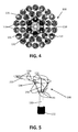
FIG. 3 andFIG. 4 illustrate a side view and a top view, respectively, of a photovoltaic energy harvesting system according to a second embodiment of a first aspect of present invention, having flexural fixtures comprising multiple loops of a resilient lineal element. -
FIG. 5 illustrates a side view of a photovoltaic energy harvesting system according to a second embodiment of a first aspect of present invention, showing only a single loop of the resilient lineal element. -
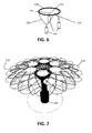
FIG. 6 illustrates a flexible fixture spacer element for use with a photovoltaic energy harvesting system according to embodiments of the present invention, making use of a single tensioning element and three driving means. -
FIG. 7 illustrates a photovoltaic energy harvesting system according to embodiments of the present invention, in a position such that the rigidity thereof is maximal. -
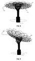
FIG. 8 illustrates a photovoltaic energy harvesting system as inFIG.7 , in a substantially horizontal position. -
FIG. 9 illustrates the photovoltaic energy harvesting system ofFIG. 7 andFIG. 8 , in an inclined position. - The drawings are only schematic and are non-limiting. In the drawings, the size of some of the elements may be exaggerated and not drawn on scale for illustrative purposes.
- Any reference signs in the claims shall not be construed as limiting the scope.
- In the different drawings, the same reference signs refer to the same or analogous elements.
- The present invention will be described with respect to particular embodiments and with reference to certain drawings but the invention is not limited thereto but only by the claims. The drawings described are only schematic and are non-limiting. In the drawings, the size of some of the elements may be exaggerated and not drawn on scale for illustrative purposes. The dimensions and the relative dimensions do not correspond to actual reductions to practice of the invention.
- The terms first, second and the like in the description and in the claims, are used for distinguishing between similar elements and not necessarily for describing a sequence, either temporally, spatially, in ranking or in any other manner. It is to be understood that the terms so used are interchangeable under appropriate circumstances and that the embodiments of the invention described herein are capable of operation in other sequences than described or illustrated herein.
- Moreover, the terms top, under and the like in the description and the claims are used for descriptive purposes and not necessarily for describing relative positions. It is to be understood that the terms so used are interchangeable under appropriate circumstances and that the embodiments of the invention described herein are capable of operation in other orientations than described or illustrated herein.
- It is to be noticed that the term "comprising", used in the claims, should not be interpreted as being restricted to the means listed thereafter; it does not exclude other elements or steps. It is thus to be interpreted as specifying the presence of the stated features, integers, steps or components as referred to, but does not preclude the presence or addition of one or more other features, integers, steps or components, or groups thereof. Thus, the scope of the expression "a device comprising means A and B" should not be limited to devices consisting only of components A and B. It means that with respect to the present invention, the only relevant components of the device are A and B.
- Reference throughout this specification to "one embodiment" or "an embodiment" means that a particular feature, structure or characteristic described in connection with the embodiment is included in at least one embodiment of the present invention. Thus, appearances of the phrases "in one embodiment" or "in an embodiment" in various places throughout this specification are not necessarily all referring to the same embodiment, but may. Furthermore, the particular features, structures or characteristics may be combined in any suitable manner, as would be apparent to one of ordinary skill in the art from this disclosure, in one or more embodiments.
- Similarly it should be appreciated that in the description of exemplary embodiments of the invention, various features of the invention are sometimes grouped together in a single embodiment, figure, or description thereof for the purpose of streamlining the disclosure and aiding in the understanding of one or more of the various inventive aspects. This method of disclosure, however, is not to be interpreted as reflecting an intention that the claimed invention requires more features than are expressly recited in each claim. Rather, as the following claims reflect, inventive aspects lie in less than all features of a single foregoing disclosed embodiment. Thus, the claims following the detailed description are hereby expressly incorporated into this detailed description, with each claim standing on its own as a separate embodiment of this invention.
- Furthermore, while some embodiments described herein include some but not other features included in other embodiments, combinations of features of different embodiments are meant to be within the scope of the invention, and form different embodiments, as would be understood by those in the art. For example, in the following claims, any of the claimed embodiments can be used in any combination.
- In the description provided herein, numerous specific details are set forth. However, it is understood that embodiments of the invention may be practiced without these specific details. In other instances, well-known methods, structures and techniques have not been shown in detail in order not to obscure an understanding of this description.
- Where in embodiments of the present invention reference is made to "flexural integrity", reference is made to the use of a material's ability to resist deformation under load so as to provide structural integrity. For example, flexural integrity refers to the use of potential energy stored in a deformed object, e.g. a bended elongate object made of material with a high flexural modulus, such as for example a bended steel wire spring, such that the object can support and resist self-weight and loads it is subjected to. Furthermore, a structure exhibiting flexural integrity is assumed to form a coherent entity, i.e. to possess internal integrity.
- In a first aspect, the present invention relates to a photovoltaic energy harvesting system. Such photovoltaic energy harvesting systems are commonly used to receive solar rays and convert them into electricity to be provided to an electrical load. Such an electrical load may for example comprise a chargeable battery, a lighting fixture, an electrical consumer appliance, an electrical or hybrid vehicle or any electrical power consuming device in general. Such an electrical load may also comprise a distribution infrastructure to supply energy to any number of such power consuming devices, such as a local power distribution grid of a private or public building or a large area power distribution grid. Such a photovoltaic energy harvesting system may comprise any number and/or combination of suitable elements for transforming, conditioning, conducting, storing and/or transmitting energy, depending on intended operational characteristics of the system, as would be evident to a person skilled in the art. Such elements may for example comprise transformers, inverters, capacitors, batteries, flywheels, interconnection wiring, gauges and/or controllers.
- By way of illustration, embodiments of the present invention not being limited thereto, an exemplary photovoltaic
energy harvesting system 100 according to a first embodiment of the first aspect of the present invention is illustrated inFIG. 1 and FIG. 2 , an exemplary photovoltaicenergy harvesting system 100 according to a second embodiment of the first aspect of the present invention is illustrated inFIG. 3 ,FIG. 4 and FIG. 5 . Both embodiments will be discussed in more detail below. They are different in the basics of theflexible fixtures 115, but they share a lot of other details. - The photovoltaic
energy harvesting system 100 according to embodiments of the present invention comprises a support. This support has a carrier structure with abase 112 andflexible fixtures 115 attached to saidbase 112. The base 112 may be fixed to or into the ground by any suitable anchoring member, such as for example a plinth or any other foundation system. The base 112 may furthermore comprise apost 113, e.g. a post extending along a substantially vertical axis to achieve a predetermined height, for example to avoid overshadowing of the photovoltaicenergy harvesting system 100 by other structures in the environment, to avoid obstruction of pedestrians and/or vehicles by the support or to reduce the risk of theft or vandalism. - It is a particular feature of embodiments of the present invention that the
flexible fixtures 115 are adapted for providing flexural integrity to the support. Theflexible fixtures 115 may form for example a number of flexible leaves or leave-like structures. In theexemplary system 100 depicted inFIG. 1 , embodiments of the invention not being limited thereto, theflexible fixtures 115 form three leaves attached to thebase 112 of the support. The leaves, being only attached at oneend 116 while theother end 117 may move freely, bend under the force of gravity until an equilibrium is reached between gravitational forces and the stresses in the material of theflexible fixtures 115 induced by the bending. The free ends 117 of the leaves may for example be interconnected byflexible bands 118, e.g. bands made of metal strings, to limit the free movement of the free ends. In such way, free movement of theflexible fixtures 115 as a group is possible while independent movement of individual elements of theflexible fixtures 115, e.g. the separate flexible leaves is restricted. In other embodiments of the present invention, if more leaves would be provided in the energy harvesting system, theflexible fixtures 115 of one leave may crossflexible fixtures 115 of another leave. Rather than linking both leaves to one another by means offlexible bands 118, other types of interconnections between the leaves may be provided, such as for example sliding bushes or hinging connections. - In particular embodiments, the
flexible fixtures 115 may comprise at least one resilient lineal element, such as a wire or a tubular element. The at least one resilient lineal element may for example consist of lengths of metal wire, e.g. wire springs composed of steel, having any appropriate cross-section, such as rectangular, oblong, elliptical or round. By preference the material, e.g. metal, of which the resilient lineal element is made, has a high tensile strength in order to make it less plastically deformable under flexion. Suitable metallic compositions are, the present invention not being limited thereto, high tensile steels, stainless steels or high carbon steels. Temperature hardened steels such as oil-hardened wires may be particularly useful. Optionally, the wires may be coated with a functional coating, for example to protect the steel from rusting, e.g. by galvanizing the steel, to provide a sufficiently sliding contact, e.g. by means of a Teflon or PET coating, or simply for aesthetic reasons. - Alternatively, other materials may be used, such as glass fiber or composite materials. In fact, any material with sufficient flexibility may be used, including, for example, biological materials such as pliable wood. In particular embodiments, two or more resilient lineal elements may be fixedly attached together, e.g. by welding, so as to form the leave-like structures. In alternative embodiments, a single
flexible fixture 115, e.g. in the form of a single resilientlineal element 210, may be formed in a loop so as to form a leave-like structure, e.g. as shown inFIG. 5 . Lineal element such as metal wire may be used to form a plurality of loops, e.g. as shown inFIG. 3 andFIG. 4 , each loop forming a leave-like structure. Flexural integrity of theflexible fixtures 115 in such a support may be obtained by interlacing the lineal element such that the flexible fixtures form a connected, yet still flexible, entity. Alternative means for providing a plurality of connections between the plurality of loops for providing flexural integrity may be used, for instance connecting pairs of loops by ringlets or small wire loops to keep such pair of loops in proximity while allowing a limited degree of relative movement. Alternatively, sliding or hinging contacts may be provided between the plurality of loops. It will be apparent to a person skilled in the art that many known methods may be used to obtain a suitable support according to embodiments of the present invention. For example, theflexible fixtures 115 may comprise a single long strand of metal wire woven in a mesh of interlocking loops, e.g. in a hypotrochoid form, or theflexible fixtures 115 may comprise a plurality of strands of metal wire, for example combined in a web-like structure. - A photovoltaic
energy harvesting system 100 according to embodiments of the present invention furthermore comprises a plurality ofphotovoltaic receptors 120. Thesephotovoltaic receptors 120 are attached by any suitable attachment means to theflexible fixtures 115 of thesupport 100. Such aphotovoltaic receptor 120 may for example comprise a photovoltaic panel, e.g. a packaged interconnected assembly of photovoltaic cells. Such photovoltaic cells are for example encapsulated between two glass layers in a photovoltaic panel. Photovoltaic panels are usually rigid, but semi-flexible panels are also known in the art. Preferably, thephotovoltaic receptors 120 used are lightweight appliances. When solar rays interact with the active surface of a photovoltaic cell, an electrical current is generated through the photovoltaic effect, which may be supplied to a load, e.g. a power consuming or power storing system. The majority of photovoltaic panels use wafer-based crystalline silicon photovoltaic cells, or thin-film cells based on cadmium telluride or silicon. - In particular embodiments of the present invention, the
flexible fixtures 115 may be adapted to conduct electricity generated by thephotovoltaic receptors 120, e.g. the flexible fixtures may comprise electrical conductors for conducting electricity generated by thephotovoltaic receptors 120. The generated electricity may for example be conducted to a means for conditioning, storing, distributing and/or converting electricity, which may for example be integrated in thebase 112 of the support. - In advantageous embodiments, the photovoltaic
energy harvesting system 100 may comprise at least oneillumination source 175, as illustrated inFIG. 3 . For instance, such illumination source could be secured to the support, e.g. fixed to the base 112 or to theflexible fixtures 115.Such illumination source 175 may for example be powered with electricity stored in a battery or other energy storage system, for example such battery or storage system integrated in thebase 112. In such cases, said battery or storage system may be charged with electricity generated by thephotovoltaic receptors 120. - The photovoltaic
energy harvesting system 100 according to embodiments of the present invention may comprise anelectricity outlet 170 for electrical and/or hybrid vehicles. In such a system, theflexible fixtures 115 could for example perform the function of a shelter to protect such vehicle from rain and/or sunlight, while providing a ecologically attractive source of power, i.e. the electricity outlet, to charge the vehicle. - It is furthermore particular to embodiments of the present invention that the photovoltaic energy harvesting system comprises a flexible
fixture spacer element 130 having at least three points offorce application force application 131 such that the direction of each of said photovoltaic receptors is collectively orientable through the action of said driving means 140. The flexiblefixture spacer element 130 is arranged so as to contact theflexible fixtures 115. The contact between thespacer element 130 and theflexible fixtures 115 may be a sliding contact, optionally restricted to movement in one direction. For example, such restricted sliding contact may be obtained by a flexiblefixture spacer element 130 comprising or consisting of two concentric rings, i.e. an inner and an outer ring, interconnected by radial connections, e.g. at least three radial rigid links, such that theflexible fixtures 115 pass between these rings. The inner ring would for example be arranged to push theflexible fixtures 115 downwardly when thespacer element 130 is pulled down by the driving means 140 so as to bend theflexible fixtures 115 downward, while the outer ring would be arranged to push from below on theflexible fixtures 115 when thespacer element 130 is pushed up by the driving means 140, so as to bend theflexible fixtures 115 upwardly. When theflexible fixtures 115 comprise a plurality of leaf-like structures, such as the leaves inFIG. 1 and FIG. 2 , or the loops of resilientlineal element 210 as illustrated inFIG. 3 andFIG. 4 , this would achieve an effect similar to the opening and closing of the leaves of a flower. Alternatively, the contact between thespacer element 130 and theflexible fixtures 115 may be a hinging contact. - In embodiments of the present invention, the flexible
fixture spacer element 130 could be a ring, e.g. a circular band of metal or any other suitable material, as illustrated inFIG. 1 . Alternatively, the flexible fixture spacer element could be a loop of any suitable form other than a ring. In yet alternative embodiments, the flexible fixture spacer element could be a plate, for example a disk-shaped plate, or a plate having any other suitable shape. - Such a spacer element,
e.g. spacer element 130, can for instance be pushed or pulled against theflexible fixtures 115 to apply force by contact to the flexible fixtures. In general the flexiblefixture spacer element 130 may be contacting the flexible fixtures so as to be able to influence the orientation of theflexible fixtures 115, and therefore thephotovoltaic receptors 120 attached thereon. The flexural integrity of the support according to the first aspect of the present invention may further ensure that the orientation of thephotovoltaic receptors 120 is collectively settable. This means that theflexible fixtures 115 may move in a collective and predictable way by driving the movement of thespacer element 130. - The system according to embodiments of the present invention comprises at least two driving means 140 for exerting forces on at least two points of
force application 131 on the flexiblefixture spacer element 130. Such driving means 140 may be linear actuators. Alternatively, the driving means 140 may comprise a pneumatic system or a hydraulic system to exert forces on the flexiblefixture spacer element 130. - Mechanical forces from at least one of the driving means 140 may be directly applied to at least one of the points of
force application 131. For example, the driving means may be a piston-cylinder combination, of which one of the piston or cylinder is directly connected to one of the points offorce application 131. - In alternative embodiments, mechanical forces from at least one of the driving means 140 to at least one of the points of
force application 131 may be transmitted by means of at least onetensioning element 150, such as for example a piece of wire, rope, strand, band or a chain. In particular embodiments, as for example illustrated inFIG. 6 , asingle tensioning element 150 may be used for moving thespacer element 130. Suchsingle tensioning element 150 should then be attached, on the one hand, at thespacer element 130 at the at least two points of force application, in the embodiments illustrated three points of force application, and on the other hand, at the at least two driving means 140, in the embodiment illustrated three drivingelements 140. In yet alternative embodiments, as illustrated inFIG.3 , each driving means 140 may be connected to one extremity ofsuch tensioning element 150, the other extremities of these tensioning elements applying the forces exerted by the driving means to the points offorce application 131 on the flexiblefixture spacer element 130. In embodiments of the present invention, the number of tensioning elements may be equal to the number of driving means. In alternative embodiments of the present invention, there may be more tensioning elements than driving means. First extremities ofdifferent tensioning elements 150 may then be connected to a single driving means, the other extremities of thesetensioning elements 150 being connected to different points of force application. - The at least one
tensioning element 150 may be a push-pull cable, at least partly guided through a flexible casing.Such tensioning 150 element may for example comprise a central push-pull cable of substantial tensile strength, e.g. a steel or stainless steel cable, and a hollow outer cable, the flexible casing, which may be of composite construction, e.g. comprising or consisting of helical steel wire lined with plastic. The at least onetensioning element 150 may for example be a Bowden cable. - While the photovoltaic
energy harvesting system 100 comprises a flexiblefixture spacer element 130 having at least three points of force application 131,132, only at least two points offorce application 131 need to receive forces exerted by the at least two driving means 140. Points offorce application 132 not receiving such forces exerted by the driving means 140 may be linked in a hinging way to thebase 132 of the support, e.g. allowing thespacer element 130 to hinge around arigid linkage 180 to thebase 132 of the support. - The application of at least two separate forces on the flexible
fixture spacer element 130 may allow to control the orientation of the flexiblefixture spacer element 130 around at least two axis of rotation, e.g. to control inclination and azimuth of thespacer element 130 and thereby, by e.g. pushing and/or pulling of thespacer element 130 on theflexible fixtures 115, control the orientation of thephotovoltaic receptors 120 attached on the leave-shaped structures. The photovoltaicenergy harvesting system 100 may comprise a controlling means 160 adapted for controlling the at least two driving means 140. The controlling means 160 may for example comprise a programmable logic controller, a proportional-integral-derivative controller or other form of electronic automation controller. The controlling means 160 may be adapted for controlling the direction of thephotovoltaic receptors 120 taking into account a predetermined path of the sun on the celestial sphere. In particular, the controlling means 160 may for example be adapted to adjust azimuth and inclination of thephotovoltaic receptors 120 as a function of reference values stored in a memory, e.g. an electronic memory, e.g. reference values based on a known position of the sun at the terrestrial location of thesystem 100 for a given date and time. Alternatively or additionally, the controlling means 160 may be adapted to adjust azimuth and inclination of thephotovoltaic receptors 120 as a function of energy output of thesystem 100, e.g. so as to improve energy output. For example, the controlling means 160 may be adapted for performing a scanning strategy to determine an adjusted position wherein the energy output of the system is higher than an initial position, e.g. by measuring the energy output of thesystem 100 while varying the azimuth and inclination of thephotovoltaic receptors 120 along a predetermined pattern, such as an outward spiraling pattern centered around the initial position, and subsequently adjusting the orientation of thephotovoltaic receptors 120 to the position for which a maximal output was measured. - The
system 100 furthermore may be actively protected from damage due to meteorological conditions, such as e.g. storms or heavy snow fall, by adjusting the orientation of thephotovoltaic receptors 120 to a position in which damage is less likely. Hereto, the controlling means 160 may be adapted for controlling the direction of thephotovoltaic receptors 120 taking into account meteorological circumstances. Protection against storm may be obtained for example, in case three points of force application on thespacer element 130 may be actively driven by drivingmeans 140, by actuating thespacer element 130 such that the rigidity of the complete structure is maximal, as for example illustrated inFIG. 7 , for example to reduce the probability of permanent damage during heavy storms, e.g. with wind speeds above 80 km/h. Alternatively, thespacer element 130 may be driven such that theflexible fixtures 115 form a structure which is as close to horizontal as possible, as illustrated inFIG. 8 , for example to minimize the wind exposure during strong winds, e.g. with wind speeds between 50 km/h and 80 km/h, or which is inclined under a pre-determined angle as desired, as illustrated inFIG. 9 , e.g. an angle of at least 30° from horizontal, e.g. an angle of 45° from the horizontal, for example to avoid piling up of snow on thesystem 100 during heavy snowfall.
Claims (15)
- A photovoltaic energy harvesting system (100) comprising- a support, said support having a carrier structure with a base (112) and flexible fixtures (115) attached to said base (112),- a plurality of photovoltaic receptors (120), said photovoltaic receptors (120) being attached to the flexible fixtures (115),characterized in that the flexible fixtures (115) are adapted for providing flexural integrity to the support, the photovoltaic energy harvesting system furthermore comprising a flexible fixture spacer element (130) having at least three points of force application (131,132) and at least two driving means (140) for exerting forces on at least two of the points of force application (131) such that the direction of each of said photovoltaic receptors (120) is collectively orientable through the action of said driving means.
- A system (100) according to claim 1, furthermore comprising at least one rigid linkage (180), said rigid linkage (180) connecting at least one of the points of force application (132) to the base (112) of said support.
- A system (100) according to claim 1, comprising three driving means (140) for exerting force on three points of force application (131) on the flexible fixture spacer element.
- A system (100) according to any of the previous claims, wherein the flexible fixture spacer element (130) is contacting said flexible fixtures (115).
- A system (100) according to any of the previous claims, furthermore comprising at least one tensioning element (150) adapted for transmission of mechanical force from at least one of said driving means (140) to at least one of said points of force application (131).
- A system (100) according to claim 5, wherein said at least one tensioning element (150) is a push-pull cable, at least partly guided through a flexible casing.
- A system (100) according to any of the previous claims, wherein the flexible fixtures (115) comprise at least one resilient lineal element (210).
- A system according to claim 7, wherein each flexible fixture is formed in a loop of a resilient lineal element (210).
- A system (100) according to claim 8, comprising a plurality of connections between said loops for providing flexural integrity to the support.
- A system (100) according to any of claims 7 to 9, wherein said at least one resilient lineal element (210) comprises glass fiber, steel or a composite material.
- A system (100) according to any of the previous claims, wherein said flexible fixtures (115) comprise electrical conductors (171) for conducting electricity generated by said photovoltaic receptors (120).
- A system (100) according to any of the previous claims, furthermore comprising a controlling means (160) adapted for controlling said at least two driving means (140).
- A system (100) according to any of the previous claims, furthermore comprising an electricity outlet (170) for electrical and/or hybrid vehicles.
- A system (100) according to any of the previous claims, furthermore comprising at least one illumination source (175).
- A system (100) according to any of the previous claims, wherein the driving means (140) are linear actuators.
Priority Applications (1)
| Application Number | Priority Date | Filing Date | Title |
|---|---|---|---|
| EP11163913A EP2518420A1 (en) | 2011-04-27 | 2011-04-27 | Photovoltaic energy harvesting system with flexible support |
Applications Claiming Priority (1)
| Application Number | Priority Date | Filing Date | Title |
|---|---|---|---|
| EP11163913A EP2518420A1 (en) | 2011-04-27 | 2011-04-27 | Photovoltaic energy harvesting system with flexible support |
Publications (1)
| Publication Number | Publication Date |
|---|---|
| EP2518420A1 true EP2518420A1 (en) | 2012-10-31 |
Family
ID=44227510
Family Applications (1)
| Application Number | Title | Priority Date | Filing Date |
|---|---|---|---|
| EP11163913A Withdrawn EP2518420A1 (en) | 2011-04-27 | 2011-04-27 | Photovoltaic energy harvesting system with flexible support |
Country Status (1)
| Country | Link |
|---|---|
| EP (1) | EP2518420A1 (en) |
Cited By (1)
| Publication number | Priority date | Publication date | Assignee | Title |
|---|---|---|---|---|
| WO2024239627A1 (en) * | 2023-05-24 | 2024-11-28 | 南昌南飞防火设备制造有限公司 | Flexible photovoltaic support capable of controlling tensioning under different conditions |
Citations (7)
| Publication number | Priority date | Publication date | Assignee | Title |
|---|---|---|---|---|
| EP1626140A2 (en) | 2004-08-09 | 2006-02-15 | Extel S.r.l. | Shelter structure for motor vehicles |
| WO2006130892A1 (en) * | 2005-06-06 | 2006-12-14 | Innova Patent Gmbh | Installation for generating electrical energy |
| WO2008064382A2 (en) * | 2006-11-30 | 2008-06-05 | Innova Patent Gmbh | System for generating electric power by means of photovoltaic elements |
| US20080168981A1 (en) * | 2006-08-25 | 2008-07-17 | Coolearth Solar | Rigging system for supporting and pointing solar concentrator arrays |
| CH699119A1 (en) * | 2008-07-14 | 2010-01-15 | Solar Wings Ag | Solar plant. |
| WO2010081184A2 (en) * | 2009-01-19 | 2010-07-22 | Innova Patent Gmbh | System for generating electric energy by using photovoltaic elements |
| US20100294265A1 (en) * | 2009-05-20 | 2010-11-25 | Zomeworks | Dual axis support for high wind solar panels |
-
2011
- 2011-04-27 EP EP11163913A patent/EP2518420A1/en not_active Withdrawn
Patent Citations (7)
| Publication number | Priority date | Publication date | Assignee | Title |
|---|---|---|---|---|
| EP1626140A2 (en) | 2004-08-09 | 2006-02-15 | Extel S.r.l. | Shelter structure for motor vehicles |
| WO2006130892A1 (en) * | 2005-06-06 | 2006-12-14 | Innova Patent Gmbh | Installation for generating electrical energy |
| US20080168981A1 (en) * | 2006-08-25 | 2008-07-17 | Coolearth Solar | Rigging system for supporting and pointing solar concentrator arrays |
| WO2008064382A2 (en) * | 2006-11-30 | 2008-06-05 | Innova Patent Gmbh | System for generating electric power by means of photovoltaic elements |
| CH699119A1 (en) * | 2008-07-14 | 2010-01-15 | Solar Wings Ag | Solar plant. |
| WO2010081184A2 (en) * | 2009-01-19 | 2010-07-22 | Innova Patent Gmbh | System for generating electric energy by using photovoltaic elements |
| US20100294265A1 (en) * | 2009-05-20 | 2010-11-25 | Zomeworks | Dual axis support for high wind solar panels |
Cited By (1)
| Publication number | Priority date | Publication date | Assignee | Title |
|---|---|---|---|---|
| WO2024239627A1 (en) * | 2023-05-24 | 2024-11-28 | 南昌南飞防火设备制造有限公司 | Flexible photovoltaic support capable of controlling tensioning under different conditions |
Similar Documents
| Publication | Publication Date | Title |
|---|---|---|
| US11489484B2 (en) | Utility pole solar energy collector system | |
| CN107027335B (en) | Portable photovoltaic module array | |
| US10840707B2 (en) | Utility pole with solar modules and wireless device and method of retrofitting existing utility pole | |
| US11207988B2 (en) | Electric or hybrid vehicle with wireless device and method of supplying electromagnetic energy to vehicle | |
| US9494343B2 (en) | Solar capture mounting systems and methods | |
| US20110056484A1 (en) | Self-erecting gimbal mounted solar radiation collectors | |
| EP2292877A1 (en) | Photovoltaic solar energy generation and vehicle cover installation | |
| EP2754186B1 (en) | Collapsible photovoltaic module for a large-scale solar power plant and method of installing said photovoltaic module | |
| US20130206708A1 (en) | Solar panel deployment system | |
| CA2828606C (en) | Methods, systems, and apparatus for natural power collection and distribution | |
| JP7532490B2 (en) | Solar power generation equipment | |
| JP7506466B2 (en) | Solar panel installation structure | |
| GB2503944A (en) | A sun Tracking Solar Panel Array | |
| US20100122722A1 (en) | Portable, durable, integrated solar power generation device | |
| EP2518420A1 (en) | Photovoltaic energy harvesting system with flexible support | |
| US9692352B2 (en) | Solar collector and conversion array | |
| US20070204860A1 (en) | Device for supporting, aligning, and cooling a solar panel | |
| US20080173345A1 (en) | Electrical energy generating device | |
| Nguyen et al. | Performance comparison between tracking and fixed photovoltaic system: A case study of Hoa Lac Hi-tech Park, Hanoi | |
| US12615006B2 (en) | Solar panel protective container apparatus and system | |
| US11652440B1 (en) | Frame elevated autonomous single axis 360 degree declination solar tracking array | |
| JP3070621U (en) | Wind solar hybrid power system | |
| Lubis et al. | Design of Bloomed Flower Patterned Solar Collector | |
| Singh et al. | Center of Excellence | |
| ITMI20100282A1 (en) | SOLAR TRACKING DEVICE |
Legal Events
| Date | Code | Title | Description |
|---|---|---|---|
| PUAI | Public reference made under article 153(3) epc to a published international application that has entered the european phase |
Free format text: ORIGINAL CODE: 0009012 |
|
| AK | Designated contracting states |
Kind code of ref document: A1 Designated state(s): AL AT BE BG CH CY CZ DE DK EE ES FI FR GB GR HR HU IE IS IT LI LT LU LV MC MK MT NL NO PL PT RO RS SE SI SK SM TR |
|
| AX | Request for extension of the european patent |
Extension state: BA ME |
|
| STAA | Information on the status of an ep patent application or granted ep patent |
Free format text: STATUS: THE APPLICATION IS DEEMED TO BE WITHDRAWN |
|
| 18D | Application deemed to be withdrawn |
Effective date: 20130503 |