EP2518296A2 - Fan drive gear system integrated carrier and torque frame - Google Patents
Fan drive gear system integrated carrier and torque frame Download PDFInfo
- Publication number
- EP2518296A2 EP2518296A2 EP12166084A EP12166084A EP2518296A2 EP 2518296 A2 EP2518296 A2 EP 2518296A2 EP 12166084 A EP12166084 A EP 12166084A EP 12166084 A EP12166084 A EP 12166084A EP 2518296 A2 EP2518296 A2 EP 2518296A2
- Authority
- EP
- European Patent Office
- Prior art keywords
- gear
- torque frame
- race
- shaft
- bearing
- Prior art date
- Legal status (The legal status is an assumption and is not a legal conclusion. Google has not performed a legal analysis and makes no representation as to the accuracy of the status listed.)
- Granted
Links
Images


Classifications
-
- F—MECHANICAL ENGINEERING; LIGHTING; HEATING; WEAPONS; BLASTING
- F16—ENGINEERING ELEMENTS AND UNITS; GENERAL MEASURES FOR PRODUCING AND MAINTAINING EFFECTIVE FUNCTIONING OF MACHINES OR INSTALLATIONS; THERMAL INSULATION IN GENERAL
- F16H—GEARING
- F16H57/00—General details of gearing
- F16H57/04—Features relating to lubrication or cooling or heating
- F16H57/042—Guidance of lubricant
- F16H57/0421—Guidance of lubricant on or within the casing, e.g. shields or baffles for collecting lubricant, tubes, pipes, grooves, channels or the like
- F16H57/0424—Lubricant guiding means in the wall of or integrated with the casing, e.g. grooves, channels, holes
-
- F—MECHANICAL ENGINEERING; LIGHTING; HEATING; WEAPONS; BLASTING
- F02—COMBUSTION ENGINES; HOT-GAS OR COMBUSTION-PRODUCT ENGINE PLANTS
- F02C—GAS-TURBINE PLANTS; AIR INTAKES FOR JET-PROPULSION PLANTS; CONTROLLING FUEL SUPPLY IN AIR-BREATHING JET-PROPULSION PLANTS
- F02C7/00—Features, components parts, details or accessories, not provided for in, or of interest apart form groups F02C1/00 - F02C6/00; Air intakes for jet-propulsion plants
- F02C7/36—Power transmission arrangements between the different shafts of the gas turbine plant, or between the gas-turbine plant and the power user
-
- F—MECHANICAL ENGINEERING; LIGHTING; HEATING; WEAPONS; BLASTING
- F02—COMBUSTION ENGINES; HOT-GAS OR COMBUSTION-PRODUCT ENGINE PLANTS
- F02K—JET-PROPULSION PLANTS
- F02K3/00—Plants including a gas turbine driving a compressor or a ducted fan
- F02K3/02—Plants including a gas turbine driving a compressor or a ducted fan in which part of the working fluid by-passes the turbine and combustion chamber
- F02K3/04—Plants including a gas turbine driving a compressor or a ducted fan in which part of the working fluid by-passes the turbine and combustion chamber the plant including ducted fans, i.e. fans with high volume, low pressure outputs, for augmenting the jet thrust, e.g. of double-flow type
- F02K3/06—Plants including a gas turbine driving a compressor or a ducted fan in which part of the working fluid by-passes the turbine and combustion chamber the plant including ducted fans, i.e. fans with high volume, low pressure outputs, for augmenting the jet thrust, e.g. of double-flow type with front fan
-
- F—MECHANICAL ENGINEERING; LIGHTING; HEATING; WEAPONS; BLASTING
- F16—ENGINEERING ELEMENTS AND UNITS; GENERAL MEASURES FOR PRODUCING AND MAINTAINING EFFECTIVE FUNCTIONING OF MACHINES OR INSTALLATIONS; THERMAL INSULATION IN GENERAL
- F16C—SHAFTS; FLEXIBLE SHAFTS; ELEMENTS OR CRANKSHAFT MECHANISMS; ROTARY BODIES OTHER THAN GEARING ELEMENTS; BEARINGS
- F16C23/00—Bearings for exclusively rotary movement adjustable for aligning or positioning
- F16C23/02—Sliding-contact bearings
- F16C23/04—Sliding-contact bearings self-adjusting
- F16C23/043—Sliding-contact bearings self-adjusting with spherical surfaces, e.g. spherical plain bearings
- F16C23/045—Sliding-contact bearings self-adjusting with spherical surfaces, e.g. spherical plain bearings for radial load mainly, e.g. radial spherical plain bearings
-
- F—MECHANICAL ENGINEERING; LIGHTING; HEATING; WEAPONS; BLASTING
- F16—ENGINEERING ELEMENTS AND UNITS; GENERAL MEASURES FOR PRODUCING AND MAINTAINING EFFECTIVE FUNCTIONING OF MACHINES OR INSTALLATIONS; THERMAL INSULATION IN GENERAL
- F16H—GEARING
- F16H1/00—Toothed gearings for conveying rotary motion
- F16H1/28—Toothed gearings for conveying rotary motion with gears having orbital motion
- F16H1/2809—Toothed gearings for conveying rotary motion with gears having orbital motion with means for equalising the distribution of load on the planet gears
- F16H1/2836—Toothed gearings for conveying rotary motion with gears having orbital motion with means for equalising the distribution of load on the planet gears by allowing limited movement of the planet gears relative to the planet carrier or by using free floating planet gears
-
- F—MECHANICAL ENGINEERING; LIGHTING; HEATING; WEAPONS; BLASTING
- F16—ENGINEERING ELEMENTS AND UNITS; GENERAL MEASURES FOR PRODUCING AND MAINTAINING EFFECTIVE FUNCTIONING OF MACHINES OR INSTALLATIONS; THERMAL INSULATION IN GENERAL
- F16H—GEARING
- F16H57/00—General details of gearing
- F16H57/04—Features relating to lubrication or cooling or heating
- F16H57/042—Guidance of lubricant
- F16H57/0427—Guidance of lubricant on rotary parts, e.g. using baffles for collecting lubricant by centrifugal force
-
- F—MECHANICAL ENGINEERING; LIGHTING; HEATING; WEAPONS; BLASTING
- F16—ENGINEERING ELEMENTS AND UNITS; GENERAL MEASURES FOR PRODUCING AND MAINTAINING EFFECTIVE FUNCTIONING OF MACHINES OR INSTALLATIONS; THERMAL INSULATION IN GENERAL
- F16H—GEARING
- F16H57/00—General details of gearing
- F16H57/04—Features relating to lubrication or cooling or heating
- F16H57/0458—Oil-mist or spray lubrication; Means to reduce foam formation
- F16H57/046—Oil-mist or spray lubrication
-
- F—MECHANICAL ENGINEERING; LIGHTING; HEATING; WEAPONS; BLASTING
- F16—ENGINEERING ELEMENTS AND UNITS; GENERAL MEASURES FOR PRODUCING AND MAINTAINING EFFECTIVE FUNCTIONING OF MACHINES OR INSTALLATIONS; THERMAL INSULATION IN GENERAL
- F16H—GEARING
- F16H57/00—General details of gearing
- F16H57/04—Features relating to lubrication or cooling or heating
- F16H57/0467—Elements of gearings to be lubricated, cooled or heated
- F16H57/0469—Bearings or seals
- F16H57/0471—Bearing
-
- F—MECHANICAL ENGINEERING; LIGHTING; HEATING; WEAPONS; BLASTING
- F16—ENGINEERING ELEMENTS AND UNITS; GENERAL MEASURES FOR PRODUCING AND MAINTAINING EFFECTIVE FUNCTIONING OF MACHINES OR INSTALLATIONS; THERMAL INSULATION IN GENERAL
- F16H—GEARING
- F16H57/00—General details of gearing
- F16H57/04—Features relating to lubrication or cooling or heating
- F16H57/0467—Elements of gearings to be lubricated, cooled or heated
- F16H57/0479—Gears or bearings on planet carriers
-
- F—MECHANICAL ENGINEERING; LIGHTING; HEATING; WEAPONS; BLASTING
- F16—ENGINEERING ELEMENTS AND UNITS; GENERAL MEASURES FOR PRODUCING AND MAINTAINING EFFECTIVE FUNCTIONING OF MACHINES OR INSTALLATIONS; THERMAL INSULATION IN GENERAL
- F16H—GEARING
- F16H57/00—General details of gearing
- F16H57/08—General details of gearing of gearings with members having orbital motion
-
- F—MECHANICAL ENGINEERING; LIGHTING; HEATING; WEAPONS; BLASTING
- F05—INDEXING SCHEMES RELATING TO ENGINES OR PUMPS IN VARIOUS SUBCLASSES OF CLASSES F01-F04
- F05D—INDEXING SCHEME FOR ASPECTS RELATING TO NON-POSITIVE-DISPLACEMENT MACHINES OR ENGINES, GAS-TURBINES OR JET-PROPULSION PLANTS
- F05D2260/00—Function
- F05D2260/40—Transmission of power
- F05D2260/403—Transmission of power through the shape of the drive components
- F05D2260/4031—Transmission of power through the shape of the drive components as in toothed gearing
- F05D2260/40311—Transmission of power through the shape of the drive components as in toothed gearing of the epicyclical, planetary or differential type
-
- F—MECHANICAL ENGINEERING; LIGHTING; HEATING; WEAPONS; BLASTING
- F16—ENGINEERING ELEMENTS AND UNITS; GENERAL MEASURES FOR PRODUCING AND MAINTAINING EFFECTIVE FUNCTIONING OF MACHINES OR INSTALLATIONS; THERMAL INSULATION IN GENERAL
- F16C—SHAFTS; FLEXIBLE SHAFTS; ELEMENTS OR CRANKSHAFT MECHANISMS; ROTARY BODIES OTHER THAN GEARING ELEMENTS; BEARINGS
- F16C2360/00—Engines or pumps
- F16C2360/23—Gas turbine engines
-
- F—MECHANICAL ENGINEERING; LIGHTING; HEATING; WEAPONS; BLASTING
- F16—ENGINEERING ELEMENTS AND UNITS; GENERAL MEASURES FOR PRODUCING AND MAINTAINING EFFECTIVE FUNCTIONING OF MACHINES OR INSTALLATIONS; THERMAL INSULATION IN GENERAL
- F16H—GEARING
- F16H57/00—General details of gearing
- F16H57/08—General details of gearing of gearings with members having orbital motion
- F16H2057/085—Bearings for orbital gears
-
- Y—GENERAL TAGGING OF NEW TECHNOLOGICAL DEVELOPMENTS; GENERAL TAGGING OF CROSS-SECTIONAL TECHNOLOGIES SPANNING OVER SEVERAL SECTIONS OF THE IPC; TECHNICAL SUBJECTS COVERED BY FORMER USPC CROSS-REFERENCE ART COLLECTIONS [XRACs] AND DIGESTS
- Y02—TECHNOLOGIES OR APPLICATIONS FOR MITIGATION OR ADAPTATION AGAINST CLIMATE CHANGE
- Y02T—CLIMATE CHANGE MITIGATION TECHNOLOGIES RELATED TO TRANSPORTATION
- Y02T50/00—Aeronautics or air transport
- Y02T50/60—Efficient propulsion technologies, e.g. for aircraft
-
- Y—GENERAL TAGGING OF NEW TECHNOLOGICAL DEVELOPMENTS; GENERAL TAGGING OF CROSS-SECTIONAL TECHNOLOGIES SPANNING OVER SEVERAL SECTIONS OF THE IPC; TECHNICAL SUBJECTS COVERED BY FORMER USPC CROSS-REFERENCE ART COLLECTIONS [XRACs] AND DIGESTS
- Y10—TECHNICAL SUBJECTS COVERED BY FORMER USPC
- Y10T—TECHNICAL SUBJECTS COVERED BY FORMER US CLASSIFICATION
- Y10T29/00—Metal working
- Y10T29/49—Method of mechanical manufacture
- Y10T29/49462—Gear making
- Y10T29/49465—Gear mounting
-
- Y—GENERAL TAGGING OF NEW TECHNOLOGICAL DEVELOPMENTS; GENERAL TAGGING OF CROSS-SECTIONAL TECHNOLOGIES SPANNING OVER SEVERAL SECTIONS OF THE IPC; TECHNICAL SUBJECTS COVERED BY FORMER USPC CROSS-REFERENCE ART COLLECTIONS [XRACs] AND DIGESTS
- Y10—TECHNICAL SUBJECTS COVERED BY FORMER USPC
- Y10T—TECHNICAL SUBJECTS COVERED BY FORMER US CLASSIFICATION
- Y10T29/00—Metal working
- Y10T29/49—Method of mechanical manufacture
- Y10T29/49636—Process for making bearing or component thereof
- Y10T29/49643—Rotary bearing
- Y10T29/49679—Anti-friction bearing or component thereof
- Y10T29/49682—Assembling of race and rolling anti-friction members
-
- Y—GENERAL TAGGING OF NEW TECHNOLOGICAL DEVELOPMENTS; GENERAL TAGGING OF CROSS-SECTIONAL TECHNOLOGIES SPANNING OVER SEVERAL SECTIONS OF THE IPC; TECHNICAL SUBJECTS COVERED BY FORMER USPC CROSS-REFERENCE ART COLLECTIONS [XRACs] AND DIGESTS
- Y10—TECHNICAL SUBJECTS COVERED BY FORMER USPC
- Y10T—TECHNICAL SUBJECTS COVERED BY FORMER US CLASSIFICATION
- Y10T74/00—Machine element or mechanism
- Y10T74/19—Gearing
- Y10T74/19642—Directly cooperating gears
-
- Y—GENERAL TAGGING OF NEW TECHNOLOGICAL DEVELOPMENTS; GENERAL TAGGING OF CROSS-SECTIONAL TECHNOLOGIES SPANNING OVER SEVERAL SECTIONS OF THE IPC; TECHNICAL SUBJECTS COVERED BY FORMER USPC CROSS-REFERENCE ART COLLECTIONS [XRACs] AND DIGESTS
- Y10—TECHNICAL SUBJECTS COVERED BY FORMER USPC
- Y10T—TECHNICAL SUBJECTS COVERED BY FORMER US CLASSIFICATION
- Y10T74/00—Machine element or mechanism
- Y10T74/19—Gearing
- Y10T74/19991—Lubrication
Definitions
- This disclosure relates to a fan drive gear system integrated carrier and torque frame.
- One type of gas turbine engine includes a fan drive gear system that is mechanically arranged between the turbo-machinery of the engine and a fan.
- the turbo-machinery is composed of two concentric shafts rotating at different speeds containing independent compressors and turbines.
- the turbo-machinery rotationally drives the fan, via the gear system, to move fluid through a nacelle which divides the fluid flow into two streams.
- An inner stream supplies the turbo-machinery and the outer stream consists of fluid which bypasses the inner stream and is solely compressed and moved by the fan.
- the fan drive gear system is provided by an epicyclic gear train and includes a centrally located input gear driven by the turbo-machinery, intermediate gears circumferentially arranged about and intermeshing with the input gear and a ring gear provided about and intermeshing the intermediate gears.
- the intermediate gears or the ring gear rotationally drives the fan in response to rotation of the input gear.
- the intermediate gears are typically supported in a carrier by a journal extending between spaced apart walls of the carrier.
- the carrier is typically constructed from a high strength metallic alloy such as steel, titanium or nickel.
- the carrier is bolted to a torque frame, which is secured to fixed structure or rotating structure depending upon the particular type of gear system.
- This integrated torque frame includes shafts that directly support the intermediate gears in a cantilevered fashion by conventional rolling element bearings. This arrangement is subjected to vibrational stresses that may cause the integrated torque frame to fail.
- a fan gear drive system includes a torque frame having a base with integrated gear shafts circumferentially spaced relative to one another. Each shaft provides a shaft axis.
- a bearing assembly is mounted on each of the gear shafts and provides a bearing assembly.
- the bearing assembly includes a spherical bearing configured to permit angular movement of the bearing axis relative to the shaft axis.
- a fan drive gear lubrication system includes a torque frame supporting multiple gears and having at least one lubrication passage.
- An oil baffle is secured to the torque frame and includes a central opening and multiple circumferentially spaced gear pockets arranged about the central opening that receive the multiple gears.
- the oil baffle includes at least one lubrication passageway in fluid communication with the lubrication passage.
- a method of assembling a fan drive gear system includes the steps of installing a spherical bearing into a race to provide a bearing assembly.
- the bearing assembly is mounted onto a shaft or torque frame.
- a gear is installed onto the bearing assembly.
- FIG. 1 An example gas turbine engine 10 is schematically illustrated in Figure 1 .
- the engine 10 includes turbo-machinery 30 having a compressor section 12 and a turbine section 14.
- the turbo-machinery 30 rotationally drives a fan 32, that is arranged in a bypass flow path 33, through an epicyclic gear train 16.
- the turbo-machinery 30 is housed within an inner nacelle 42.
- Flow exit guide vanes 31 arranged within the bypass flow path support the turbo-machinery 30 relative to a fan case, which is housed in a fan nacelle 44.
- a low pressure compressor 18 and a low pressure turbine 20 are mounted on a low pressure spool 22.
- a high pressure compressor 24 and a high pressure turbine 26 are mounted on a high pressure spool 28.
- a combustor section 48 is arranged between the high pressure compressor 24 and the high pressure turbine 26.
- the low pressure spool 22 rotationally drives a flex shaft 46 to which an input gear 36 (sun gear) is mounted for rotation about an axis A.
- Intermediate gears 38 (in the example, star gears) are arranged circumferentially about and intermesh with the input gear 36.
- a ring gear 40 surrounds and intermeshes with the intermediate gears 38. Either the intermediate gears 38 or the ring gear 40 rotationally drives the fan shaft 34 depending upon the type of epicyclic gear train configuration.
- the epicyclic gear train 16 is the type in which the intermediate gears 38 (star gears, in the example) are rotationally fixed relative to the rotational axis of the input gear 36. That is, the star gears are permitted to rotate about their respective rotational axes but do not rotate about the rotational axis of the input gear 36.
- the ring gear 40 is coupled to the fan shaft 34 to rotationally drive the fan 32.
- the turbo-machinery 30 includes fixed structure 50 comprising a bearing compartment case 52 and a support member 54.
- a torque frame 56 is affixed to the support member 54 to prevent rotation of the torque frame 56 about the rotational axis A of the input gear 36.
- the torque frame 56 would rotate about the rotational axis A and the ring gear would be coupled to fixed structure.
- the torque frame 56 includes multiple shafts 58 integral with a base 61 that provides first and second support features 62, 64 affixed to the support member 54.
- the torque frame 56 includes five equally circumferentially spaced shafts 58 that correspondingly support five star gears.
- the base 61 and shafts 58 of the torque frame 56 are unitary and formed by a one-piece structure, for example, by a cast steel structure. Other high strength metallic alloys, such titanium or nickel, may also be used.
- Each shaft 58 includes a bearing assembly 60 for rotationally supporting its respective intermediate gear 38.
- An oil baffle 66 is secured to the torque frame 56 by fasteners 74.
- the oil baffle 66 is non-structural. That is, the oil baffle does not support the loads of the intermediate gears 38 as would a prior art carrier.
- the oil baffle 66 may be constructed from a considerably lower strength lighter weight material, such as an aluminum alloy or composite material.
- Both the torque frame 56 and the oil baffle 66 provide internal lubrication features for supplying lubricating fluid, such as oil, to the gears of the epicyclic gear train 16.
- a feed tube 68 supplies oil to first and second passages 70, 72 provided in the torque frame 56.
- a tube 76 fluidly interconnects the second passage 72 to a spray bar 78 provided integrally in the oil baffle 66.
- the spray bar 78 includes a first passageway 80, which extends in a generally axial direction in the example shown, and one or more second passageways 82 transverse to the first passageway 80.
- a pair of second passageways 82 are oriented to direct lubrication fluid radially inward at teeth 84 of the input gear 36.
- each shaft 58 includes an end 86 that supports a bearing assembly 60.
- the bearing assembly 60 includes a spherical bearing 88 supported in a race 90 on which the intermediate gear 38 is mounted.
- the ends 86 include a threaded portion that each receives a nut 91 securing the bearing assembly 60 to the shaft 58.
- the shaft 58, spherical bearing 88 and race 90 respectively include radially extending first, second and third passageways 92, 94, 96 that are aligned with one another to deliver lubricating fluid from the first passage 70 to bearing surfaces 98 provided between the race 90 and the intermediate gear 38.
- a recess 99 is provided in an outer diameter of the race 90 to increase lubrication at the bearing surfaces 98.
- a filter 100 is arranged in a hole in the shaft 58 that provides a portion of the first passage 70.
- the spherical bearing 88 includes an inner diameter 102 that is supported by the end 86.
- a convex surface 104 is provided on an outside of the spherical bearing 88 and mates with a corresponding concave surface 112 provided by an inner surface of the race 90 when fully assembled as illustrated in Figure 5B .
- the spherical bearing 88 includes a pin 106 that extends through both the inner diameter 102 and the convex surface 104 in the example illustrated.
- the pin 106 is received by notches 110, 114 respectively provided in the race 90 and end 86 to prevent rotation of the spherical bearing 88 about a bearing axis B ( Figure 5B ).
- the spherical bearing 88 permits angular movement of the bearing axis B relative to a shaft axis T ( Figure 3 ) provided by the shaft 58 during flexing of the shafts 58, which provides a near zero moment restraint.
- Figures 5A and 5B illustrate the assembly process of the bearing assembly 60.
- the spherical bearing 88 is inserted into slots 108 of the race 90, as shown in Figure 5A .
- the pin 106 is aligned with the notch 110 and the spherical bearing 88 is rotated to snap into engagement with the concave surface 112 with the pin 106 received in the notch 110.
- the second and third passageways 94, 96 are aligned with one another.
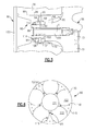
- the oil baffle 66 is illustrated in more detail in Figure 6 .
- the oil baffle 66 is provided by a body 116 having circumferentially spaced apart intermediate structures 118 axially extending from a wall 120.
- the intermediate structures 118 define gear pockets 122 within which the intermediate gears 38 are received with the epicyclic gear train 16 fully assembled.
- the input gear 36 is received in a central opening 124 provided radially inward of the intermediate structures 118.
- Holes 126 are provided in the intermediate structures 118 and receive the fasteners 74 to secure the oil baffle 66 to the torque frame 56, as illustrated in Figure 2 .
Landscapes
- Engineering & Computer Science (AREA)
- General Engineering & Computer Science (AREA)
- Mechanical Engineering (AREA)
- Chemical & Material Sciences (AREA)
- Combustion & Propulsion (AREA)
- Oil, Petroleum & Natural Gas (AREA)
- General Details Of Gearings (AREA)
- Retarders (AREA)
- Support Of The Bearing (AREA)
- Sliding-Contact Bearings (AREA)
Abstract
Description
- This disclosure relates to a fan drive gear system integrated carrier and torque frame.
- One type of gas turbine engine includes a fan drive gear system that is mechanically arranged between the turbo-machinery of the engine and a fan. The turbo-machinery is composed of two concentric shafts rotating at different speeds containing independent compressors and turbines. The turbo-machinery rotationally drives the fan, via the gear system, to move fluid through a nacelle which divides the fluid flow into two streams. An inner stream supplies the turbo-machinery and the outer stream consists of fluid which bypasses the inner stream and is solely compressed and moved by the fan.
- Typically the fan drive gear system is provided by an epicyclic gear train and includes a centrally located input gear driven by the turbo-machinery, intermediate gears circumferentially arranged about and intermeshing with the input gear and a ring gear provided about and intermeshing the intermediate gears. Depending upon the configuration, either the intermediate gears or the ring gear rotationally drives the fan in response to rotation of the input gear.
- The intermediate gears are typically supported in a carrier by a journal extending between spaced apart walls of the carrier. The carrier is typically constructed from a high strength metallic alloy such as steel, titanium or nickel. The carrier is bolted to a torque frame, which is secured to fixed structure or rotating structure depending upon the particular type of gear system.
- One type of gear system for helicopter applications has been used which directly supports the intermediate gears on an integrated carrier and torque frame. This integrated torque frame includes shafts that directly support the intermediate gears in a cantilevered fashion by conventional rolling element bearings. This arrangement is subjected to vibrational stresses that may cause the integrated torque frame to fail.
- A fan gear drive system includes a torque frame having a base with integrated gear shafts circumferentially spaced relative to one another. Each shaft provides a shaft axis. A bearing assembly is mounted on each of the gear shafts and provides a bearing assembly. The bearing assembly includes a spherical bearing configured to permit angular movement of the bearing axis relative to the shaft axis.
- A fan drive gear lubrication system includes a torque frame supporting multiple gears and having at least one lubrication passage. An oil baffle is secured to the torque frame and includes a central opening and multiple circumferentially spaced gear pockets arranged about the central opening that receive the multiple gears. The oil baffle includes at least one lubrication passageway in fluid communication with the lubrication passage.
- A method of assembling a fan drive gear system includes the steps of installing a spherical bearing into a race to provide a bearing assembly. The bearing assembly is mounted onto a shaft or torque frame. A gear is installed onto the bearing assembly.
- The disclosure can be further understood by reference to the following detailed description when considered in connection with the accompanying drawings wherein:
-
Figure 1 is a schematic cross-sectional view of an example gas turbine engine. -
Figure 2 is a cross-sectional view of an example fan drive gear system. -
Figure 3 is an enlarged cross-sectional view of a portion of the fan drive gear system illustrated inFigure 2 . -
Figure 4 is a perspective view of an example spherical bearing. -
Figure 5A is an elevational view of the spherical bearing ofFigure 4 inserted into a race in an assembly position. -
Figure 5B is an elevational view of the spherical bearing ofFigure 4 fully assembled into the race to provide a bearing assembly. -
Figure 6 is an elevational view of an example oil baffle used in the fan drive gear system and illustrated inFigures 2 and3 . - An example
gas turbine engine 10 is schematically illustrated inFigure 1 . Theengine 10 includes turbo-machinery 30 having acompressor section 12 and a turbine section 14. The turbo-machinery 30 rotationally drives afan 32, that is arranged in abypass flow path 33, through anepicyclic gear train 16. The turbo-machinery 30 is housed within aninner nacelle 42. Flowexit guide vanes 31 arranged within the bypass flow path support the turbo-machinery 30 relative to a fan case, which is housed in afan nacelle 44. - A
low pressure compressor 18 and alow pressure turbine 20 are mounted on alow pressure spool 22. Ahigh pressure compressor 24 and ahigh pressure turbine 26 are mounted on ahigh pressure spool 28. Acombustor section 48 is arranged between thehigh pressure compressor 24 and thehigh pressure turbine 26. - The
low pressure spool 22 rotationally drives aflex shaft 46 to which an input gear 36 (sun gear) is mounted for rotation about an axis A. Intermediate gears 38 (in the example, star gears) are arranged circumferentially about and intermesh with theinput gear 36. Aring gear 40 surrounds and intermeshes with theintermediate gears 38. Either theintermediate gears 38 or thering gear 40 rotationally drives thefan shaft 34 depending upon the type of epicyclic gear train configuration. - One example
epicyclic gear train 16 is illustrated inFigure 2 . Theepicyclic gear train 16 is the type in which the intermediate gears 38 (star gears, in the example) are rotationally fixed relative to the rotational axis of theinput gear 36. That is, the star gears are permitted to rotate about their respective rotational axes but do not rotate about the rotational axis of theinput gear 36. Thering gear 40 is coupled to thefan shaft 34 to rotationally drive thefan 32. The turbo-machinery 30 includesfixed structure 50 comprising abearing compartment case 52 and asupport member 54. Atorque frame 56 is affixed to thesupport member 54 to prevent rotation of thetorque frame 56 about the rotational axis A of theinput gear 36. However, it should be understood that in a planetary gear configuration thetorque frame 56 would rotate about the rotational axis A and the ring gear would be coupled to fixed structure. - The
torque frame 56 includesmultiple shafts 58 integral with abase 61 that provides first andsecond support features support member 54. In the example, thetorque frame 56 includes five equally circumferentially spacedshafts 58 that correspondingly support five star gears. Thebase 61 andshafts 58 of thetorque frame 56 are unitary and formed by a one-piece structure, for example, by a cast steel structure. Other high strength metallic alloys, such titanium or nickel, may also be used. - Each
shaft 58 includes abearing assembly 60 for rotationally supporting its respectiveintermediate gear 38. Anoil baffle 66 is secured to thetorque frame 56 byfasteners 74. Theoil baffle 66 is non-structural. That is, the oil baffle does not support the loads of theintermediate gears 38 as would a prior art carrier. As a result, theoil baffle 66 may be constructed from a considerably lower strength lighter weight material, such as an aluminum alloy or composite material. - Both the
torque frame 56 and theoil baffle 66 provide internal lubrication features for supplying lubricating fluid, such as oil, to the gears of theepicyclic gear train 16. As an example, afeed tube 68 supplies oil to first andsecond passages torque frame 56. Atube 76 fluidly interconnects thesecond passage 72 to aspray bar 78 provided integrally in theoil baffle 66. Thespray bar 78 includes afirst passageway 80, which extends in a generally axial direction in the example shown, and one or moresecond passageways 82 transverse to thefirst passageway 80. In the example, a pair ofsecond passageways 82 are oriented to direct lubrication fluid radially inward atteeth 84 of theinput gear 36. - Referring to
Figure 3 , eachshaft 58 includes anend 86 that supports a bearingassembly 60. The bearingassembly 60 includes aspherical bearing 88 supported in arace 90 on which theintermediate gear 38 is mounted. The ends 86 include a threaded portion that each receives anut 91 securing the bearingassembly 60 to theshaft 58. Theshaft 58,spherical bearing 88 andrace 90 respectively include radially extending first, second andthird passageways first passage 70 to bearingsurfaces 98 provided between therace 90 and theintermediate gear 38. Arecess 99 is provided in an outer diameter of therace 90 to increase lubrication at the bearing surfaces 98. In one example, afilter 100 is arranged in a hole in theshaft 58 that provides a portion of thefirst passage 70. - Referring to
Figures 3-5B , thespherical bearing 88 includes aninner diameter 102 that is supported by theend 86. Aconvex surface 104 is provided on an outside of thespherical bearing 88 and mates with a correspondingconcave surface 112 provided by an inner surface of therace 90 when fully assembled as illustrated inFigure 5B . Thespherical bearing 88 includes apin 106 that extends through both theinner diameter 102 and theconvex surface 104 in the example illustrated. Thepin 106 is received bynotches race 90 and end 86 to prevent rotation of thespherical bearing 88 about a bearing axis B (Figure 5B ). Thespherical bearing 88 permits angular movement of the bearing axis B relative to a shaft axis T (Figure 3 ) provided by theshaft 58 during flexing of theshafts 58, which provides a near zero moment restraint. -
Figures 5A and 5B illustrate the assembly process of the bearingassembly 60. Thespherical bearing 88 is inserted intoslots 108 of therace 90, as shown inFigure 5A . Thepin 106 is aligned with thenotch 110 and thespherical bearing 88 is rotated to snap into engagement with theconcave surface 112 with thepin 106 received in thenotch 110. In this position, illustrated inFigure 5B , the second andthird passageways - The
oil baffle 66 is illustrated in more detail inFigure 6 . Theoil baffle 66 is provided by abody 116 having circumferentially spaced apartintermediate structures 118 axially extending from awall 120. Theintermediate structures 118 definegear pockets 122 within which theintermediate gears 38 are received with theepicyclic gear train 16 fully assembled. Theinput gear 36 is received in acentral opening 124 provided radially inward of theintermediate structures 118.Holes 126 are provided in theintermediate structures 118 and receive thefasteners 74 to secure theoil baffle 66 to thetorque frame 56, as illustrated inFigure 2 . - Although an example embodiment has been disclosed, a worker of ordinary skill in this art would recognize that certain modifications would come within the scope of the claims. For that reason, the following claims should be studied to determine their true scope and content.
Claims (15)
- A fan gear drive system comprising:a torque frame (56) comprising a base (61) with integrated gear shafts (58) circumferentially spaced relative to one another, each shaft providing a shaft axis (T); anda bearing assembly (60) mounted on each of the gear shafts (58) and providing a bearing axis (B), the bearing assembly (60) including a spherical bearing (88) configured to permit angular movement of the bearing axis (B) relative to the shaft axis (T).
- The system according to claim 1, comprising a gear (38) supported on each bearing assembly for rotation about the bearing axis, an input gear (36) located radially inward from and intermeshing with intermediate gears (38) supported on the gear shafts (58), and a ring gear (40) arranged about and intermeshing with the intermediate gears (38), the input gear (36) supported by an input shaft (46), and a fixed structure (50) supporting one of the ring gear (40) and the torque frame (56), and the other of the ring gear (40) and the torque frame (56) is coupled to a fan shaft (34); preferably wherein the system is a star gear system in which the ring gear (40) is coupled to the fan shaft (34) and the torque frame (36) is secured to the fixed structure (50).
- The system according to claim 1 or 2, wherein the bearing assembly (60) includes a race (90) supporting the gear (38), and the spherical bearing (88) is received by the race (90), and a pin (106) configured to prevent relative rotation between the race (90), spherical bearing (88) and the shaft (58) about the shaft axis (T).
- The system according to claim 1, 2 or 3, wherein the torque frame (56) includes an oil passage (70,72) provided through the shaft (58) and configured to provide lubricating fluid to the gears (38).
- The system according to claim 4, wherein the bearing assembly (60) includes at least one passageway (94,96) extending through each of the spherical bearing (88) and the race (90) and in fluid communication with the passage (70).
- The system according to claim 4 or 5, comprising an oil baffle (66) supported by the torque frame (56) and in fluid communication with the passage (70,72), a spray bar (78) provided in the oil baffle (66) and configured to direct lubricating fluid at teeth (84) of at least one of the input gear (36) and the intermediate gears (38); preferably wherein the torque frame (56) is constructed from a high strength metallic alloy, and the oil baffle (66) is constructed from a lower strength lighter weight alloy than the high strength metallic alloy.
- A fan drive gear drive lubrication system comprising:a torque frame (56) supporting multiple gears (38) and including at least one lubrication passage (70,72); andan oil baffle (66) secured to the torque frame (56) and including a central opening (124) and multiple circumferentially spaced gear pockets (122) arranged about the central opening and receiving the multiple gears (38), the oil baffle (66) including at least one lubrication passageway (80) in fluid communication with the lubrication passage (70,72).
- The system according to claim 7, wherein the torque frame (56) includes a base (61) with integrated gear shafts (38) circumferentially spaced relative to one another and supporting the multiple gears (34); preferably wherein the torque frame (56) is constructed from a high strength metallic alloy, and the oil baffle (66) is constructed from a lower strength lighter weight alloy than the high strength metallic alloy.
- The system according to claim 8, wherein a bearing assembly (80) is mounted on each shaft (38) and includes a race (90) receiving a spherical bearing (88), and at least one passageway (94,96) extending through each of the spherical bearing (88) and the race (90) and in fluid communication with the lubrication passage (70).
- The system according to claim 8 or 9, wherein the at least one lubrication passageway (70,72) includes a spray bar (74) configured to direct lubricating fluid at teeth (84) of a gear (36,38).
- A method of assembling a fan drive gear system comprising the steps of:installing a spherical bearing (88) into a race (90) to provide a bearing assembly (60);mounting the bearing assembly (60) onto a shaft (58) of a torque frame (56); andinstalling a gear (38) onto the bearing assembly (60).
- The method according to claim 11, wherein the installing step includes inserting a spherical bearing (88) into slots (108) in the race (90) and rotating the spherical bearing (88) and the race (90) relative to one another to seat the spherical bearing within the race; preferably wherein the installing step includes aligning first and second lubrication passageways (94,96) provided in the spherical bearing (88) and race (90) with one another.
- The method according to claim 11 or 12, wherein the installing step includes locating a pin (106) within a notch (110), and the mounting step includes securing a fastening element (91) to the shaft (58) to retain the bearing assembly (60) on the torque frame (56).
- The method according to claim 11, 12 or 13, comprising the step of securing the torque frame (56) to a first structure (54) and input gear (36) to a second structure, and the installing steps includes installing intermediate gears (38) around the input gear (36).
- The method according to claim 11, 12, 13 or 14, comprising the step of securing an oil baffle (66) to the torque frame (56) and fluidly connecting lubrication passages (70) in the torque frame to lubrication passageways (80) in the oil baffle; preferably wherein the lubrication passageways (70,72) include a spray bar (78) facing an input gear (36).
Priority Applications (1)
| Application Number | Priority Date | Filing Date | Title |
|---|---|---|---|
| EP19182395.4A EP3564512B1 (en) | 2011-04-27 | 2012-04-27 | Fan drive gear system integrated carrier and torque frame |
Applications Claiming Priority (1)
| Application Number | Priority Date | Filing Date | Title |
|---|---|---|---|
| US13/095,324 US8900083B2 (en) | 2011-04-27 | 2011-04-27 | Fan drive gear system integrated carrier and torque frame |
Related Child Applications (2)
| Application Number | Title | Priority Date | Filing Date |
|---|---|---|---|
| EP19182395.4A Division EP3564512B1 (en) | 2011-04-27 | 2012-04-27 | Fan drive gear system integrated carrier and torque frame |
| EP19182395.4A Division-Into EP3564512B1 (en) | 2011-04-27 | 2012-04-27 | Fan drive gear system integrated carrier and torque frame |
Publications (3)
| Publication Number | Publication Date |
|---|---|
| EP2518296A2 true EP2518296A2 (en) | 2012-10-31 |
| EP2518296A3 EP2518296A3 (en) | 2018-04-11 |
| EP2518296B1 EP2518296B1 (en) | 2019-08-07 |
Family
ID=46045902
Family Applications (2)
| Application Number | Title | Priority Date | Filing Date |
|---|---|---|---|
| EP19182395.4A Active EP3564512B1 (en) | 2011-04-27 | 2012-04-27 | Fan drive gear system integrated carrier and torque frame |
| EP12166084.9A Active EP2518296B1 (en) | 2011-04-27 | 2012-04-27 | Fan drive gear system integrated carrier and torque frame |
Family Applications Before (1)
| Application Number | Title | Priority Date | Filing Date |
|---|---|---|---|
| EP19182395.4A Active EP3564512B1 (en) | 2011-04-27 | 2012-04-27 | Fan drive gear system integrated carrier and torque frame |
Country Status (2)
| Country | Link |
|---|---|
| US (2) | US8900083B2 (en) |
| EP (2) | EP3564512B1 (en) |
Cited By (7)
| Publication number | Priority date | Publication date | Assignee | Title |
|---|---|---|---|---|
| EP3001020A1 (en) * | 2014-09-26 | 2016-03-30 | Rolls-Royce Deutschland Ltd & Co KG | Aircraft engine comprising a compressor |
| EP3473892A1 (en) * | 2017-10-18 | 2019-04-24 | Ge Avio S.r.l. | Gearbox for a gas turbine engine |
| EP3489550A1 (en) * | 2017-11-24 | 2019-05-29 | Rolls-Royce Deutschland Ltd & Co KG | Planetary gear and journal bearing pin for a planetary gear |
| US10816087B2 (en) | 2017-11-24 | 2020-10-27 | Rolls-Royce Deutschland Ltd & Co Kg | Planetary gearing and planet pin for a planetary gearing |
| US10890247B2 (en) | 2017-10-19 | 2021-01-12 | Ge Avio S.R.L | Lubrication fluid collection in a gearbox of a gas turbine engine |
| US11085523B2 (en) | 2017-11-24 | 2021-08-10 | Rolls-Royce Deutschland Ltd & Co Kg | Planetary gearing |
| EP4230856A1 (en) * | 2022-02-16 | 2023-08-23 | Pratt & Whitney Canada Corp. | Epicyclic gear train of aircraft powerplant |
Families Citing this family (23)
| Publication number | Priority date | Publication date | Assignee | Title |
|---|---|---|---|---|
| US8585538B2 (en) * | 2006-07-05 | 2013-11-19 | United Technologies Corporation | Coupling system for a star gear train in a gas turbine engine |
| US8777793B2 (en) | 2011-04-27 | 2014-07-15 | United Technologies Corporation | Fan drive planetary gear system integrated carrier and torque frame |
| ITTO20111007A1 (en) * | 2011-11-03 | 2013-05-04 | Avio Spa | EPICYCLOIDAL ROTISM |
| US9328818B2 (en) * | 2012-09-21 | 2016-05-03 | United Technologies Corporation | Gear carrier flex mount lubrication |
| US8900090B2 (en) * | 2012-11-30 | 2014-12-02 | United Technologies Corporation | Geared architecture gas turbine engine with improved lubrication and misalignment tolerant roller bearing system |
| US9926850B2 (en) | 2013-02-11 | 2018-03-27 | United Technologies Corporation | Compound star gear system with rolling element bearings |
| US10215053B2 (en) | 2013-07-07 | 2019-02-26 | United Technologies Corporation | Fan drive gear system manifold radial tube filters |
| US9726083B2 (en) * | 2013-08-21 | 2017-08-08 | United Technologies Corporation | Load balanced journal bearing pin for planetary gear |
| US10533522B2 (en) | 2013-08-21 | 2020-01-14 | United Technologies Corporation | Load balanced journal bearing pin |
| PL3092142T3 (en) * | 2014-01-10 | 2019-05-31 | Gkn Driveline North America Inc | Vehicle power transfer unit (ptu) with oil feed passage |
| US10280843B2 (en) | 2014-03-07 | 2019-05-07 | United Technologies Corporation | Geared turbofan with integral front support and carrier |
| US9939058B2 (en) * | 2015-02-10 | 2018-04-10 | Prett & Whitney Canada Corp. | Gearbox having gear baffle apparatus |
| US10119465B2 (en) | 2015-06-23 | 2018-11-06 | United Technologies Corporation | Geared turbofan with independent flexible ring gears and oil collectors |
| US10508562B2 (en) * | 2015-12-01 | 2019-12-17 | United Technologies Corporation | Geared turbofan with four star/planetary gear reduction |
| ITUA20162733A1 (en) * | 2016-04-20 | 2017-10-20 | Ge Avio Srl | OIL TRANSFER UNIT TO TRANSFER OIL BETWEEN A STATIC PART AND A ROTATING PART |
| FR3073915B1 (en) * | 2017-11-17 | 2019-10-25 | Safran Transmission Systems | TURBOMACHINE PLANETARY OR EPICYCLOIDAL TRAIN SPEED CAGE |
| DE102017127874A1 (en) * | 2017-11-24 | 2019-05-29 | Rolls-Royce Deutschland Ltd & Co Kg | Planetary gear and planetary gear for a planetary gear |
| DE102017127866A1 (en) * | 2017-11-24 | 2019-05-29 | Rolls-Royce Deutschland Ltd & Co Kg | Planetary gear and plain bearing pin for a planetary gear |
| FR3084428B1 (en) * | 2018-07-26 | 2020-09-11 | Safran Trans Systems | PLANETARY OR EPICYCLOIDAL GEAR REDUCER CAGE FOR TURBOMACHINE |
| US11680525B2 (en) | 2021-08-20 | 2023-06-20 | Pratt & Whitney Canada Corp. | Lubricant filter for a turbine engine |
| US11821364B2 (en) | 2021-08-20 | 2023-11-21 | Pratt & Whitney Canada Corp. | Shaped cavity at interface between journal bearing and rotor |
| US11814975B2 (en) | 2021-08-20 | 2023-11-14 | Pratt & Whitney Canada Corp. | Feed circuit with slot(s) at interface between journal bearing and rotor |
| DE102023100468A1 (en) * | 2023-01-11 | 2024-07-11 | Voith Patent Gmbh | Improved bearings for planetary gears |
Family Cites Families (24)
| Publication number | Priority date | Publication date | Assignee | Title |
|---|---|---|---|---|
| BE436044A (en) * | 1938-03-10 | |||
| US2749778A (en) * | 1952-03-11 | 1956-06-12 | Farrel Birmingham Co Inc | Articulated planetary gearing |
| GB798273A (en) * | 1955-11-04 | 1958-07-16 | Gen Motors Corp | Improvements relating to planetary gearing |
| US3227006A (en) * | 1963-01-14 | 1966-01-04 | Bell Aerospace Corp | Power transmitting gear train |
| US3257869A (en) * | 1963-09-20 | 1966-06-28 | Pennsalt Chemicals Corp | Planetary gearing |
| US3352178A (en) * | 1965-11-15 | 1967-11-14 | Gen Motors Corp | Planetary gearing |
| US3635103A (en) * | 1968-12-24 | 1972-01-18 | Siai Marchetti Spa | Planetary reduction gearing |
| US5102379A (en) | 1991-03-25 | 1992-04-07 | United Technologies Corporation | Journal bearing arrangement |
| IT1250861B (en) | 1991-11-12 | 1995-04-21 | Fiat Avio Spa | EPICYCLOIDAL SPEED REDUCER SUITABLE TO BE INSERTED IN THE TRANSMISSION BETWEEN A GAS TURBINE AND THE AIR COMPRESSOR OF AN AIRCRAFT ENGINE. |
| US5466198A (en) * | 1993-06-11 | 1995-11-14 | United Technologies Corporation | Geared drive system for a bladed propulsor |
| US5433674A (en) | 1994-04-12 | 1995-07-18 | United Technologies Corporation | Coupling system for a planetary gear train |
| US6223616B1 (en) | 1999-12-22 | 2001-05-01 | United Technologies Corporation | Star gear system with lubrication circuit and lubrication method therefor |
| US6663530B2 (en) | 2001-12-14 | 2003-12-16 | Pratt & Whitney Canada Corp. | Zero twist carrier |
| US7220057B2 (en) * | 2002-02-15 | 2007-05-22 | Brueninghaus Hydromatik Gmbh | Rotation-slide bearing |
| US7104918B2 (en) * | 2003-07-29 | 2006-09-12 | Pratt & Whitney Canada Corp. | Compact epicyclic gear carrier |
| US7033301B2 (en) * | 2004-02-26 | 2006-04-25 | Ford Global Technologies, Llc | Planet pinion carrier assembly for Ravigneaux gearset |
| US8267826B2 (en) * | 2005-03-15 | 2012-09-18 | United Technologies Corporation | Uninterruptible oil supply in planetary system |
| GB0518026D0 (en) * | 2005-09-06 | 2005-10-12 | Orbital 2 Ltd | A gear |
| US8585538B2 (en) | 2006-07-05 | 2013-11-19 | United Technologies Corporation | Coupling system for a star gear train in a gas turbine engine |
| US7704178B2 (en) | 2006-07-05 | 2010-04-27 | United Technologies Corporation | Oil baffle for gas turbine fan drive gear system |
| GB0905110D0 (en) | 2009-03-25 | 2009-05-06 | Rolls Royce Plc | Bearing arrangement |
| US8813469B2 (en) | 2010-10-12 | 2014-08-26 | United Technologies Corporation | Planetary gear system arrangement with auxiliary oil system |
| US8777793B2 (en) * | 2011-04-27 | 2014-07-15 | United Technologies Corporation | Fan drive planetary gear system integrated carrier and torque frame |
| US9863326B2 (en) * | 2013-03-12 | 2018-01-09 | United Technologies Corporation | Flexible coupling for geared turbine engine |
-
2011
- 2011-04-27 US US13/095,324 patent/US8900083B2/en active Active
-
2012
- 2012-04-27 EP EP19182395.4A patent/EP3564512B1/en active Active
- 2012-04-27 EP EP12166084.9A patent/EP2518296B1/en active Active
-
2014
- 2014-09-12 US US14/484,673 patent/US9732839B2/en active Active
Non-Patent Citations (1)
| Title |
|---|
| None |
Cited By (10)
| Publication number | Priority date | Publication date | Assignee | Title |
|---|---|---|---|---|
| EP3001020A1 (en) * | 2014-09-26 | 2016-03-30 | Rolls-Royce Deutschland Ltd & Co KG | Aircraft engine comprising a compressor |
| US10119548B2 (en) | 2014-09-26 | 2018-11-06 | Rolls-Royce Deutschland Ltd & Co Kg | Aircraft engine with a compressor device |
| EP3473892A1 (en) * | 2017-10-18 | 2019-04-24 | Ge Avio S.r.l. | Gearbox for a gas turbine engine |
| US10823083B2 (en) | 2017-10-18 | 2020-11-03 | Ge Avio S.R.L. | Gearbox for a gas turbine engine |
| US10890247B2 (en) | 2017-10-19 | 2021-01-12 | Ge Avio S.R.L | Lubrication fluid collection in a gearbox of a gas turbine engine |
| EP3489550A1 (en) * | 2017-11-24 | 2019-05-29 | Rolls-Royce Deutschland Ltd & Co KG | Planetary gear and journal bearing pin for a planetary gear |
| US10767755B2 (en) | 2017-11-24 | 2020-09-08 | Rolls-Royce Deutschland Ltd & Co Kg | Planetary gearing and planet pin for a planetary gearing |
| US10816087B2 (en) | 2017-11-24 | 2020-10-27 | Rolls-Royce Deutschland Ltd & Co Kg | Planetary gearing and planet pin for a planetary gearing |
| US11085523B2 (en) | 2017-11-24 | 2021-08-10 | Rolls-Royce Deutschland Ltd & Co Kg | Planetary gearing |
| EP4230856A1 (en) * | 2022-02-16 | 2023-08-23 | Pratt & Whitney Canada Corp. | Epicyclic gear train of aircraft powerplant |
Also Published As
| Publication number | Publication date |
|---|---|
| EP2518296A3 (en) | 2018-04-11 |
| EP3564512B1 (en) | 2021-06-02 |
| EP3564512A1 (en) | 2019-11-06 |
| US20150323056A1 (en) | 2015-11-12 |
| US9732839B2 (en) | 2017-08-15 |
| EP2518296B1 (en) | 2019-08-07 |
| US20120272762A1 (en) | 2012-11-01 |
| US8900083B2 (en) | 2014-12-02 |
Similar Documents
| Publication | Publication Date | Title |
|---|---|---|
| US8900083B2 (en) | Fan drive gear system integrated carrier and torque frame | |
| US9068629B2 (en) | Fan drive planetary gear system integrated carrier and torque frame | |
| US8899916B2 (en) | Torque frame and asymmetric journal bearing for fan drive gear system | |
| US8845277B2 (en) | Geared turbofan engine with integral gear and bearing supports | |
| EP2546494B1 (en) | Assembly method for a gas turbine fan drive gear system | |
| EP2264336B1 (en) | Epicyclic gear system with improved lubrication system | |
| EP3855003B1 (en) | Planetary gear system arrangement with auxiliary oil system |
Legal Events
| Date | Code | Title | Description |
|---|---|---|---|
| PUAI | Public reference made under article 153(3) epc to a published international application that has entered the european phase |
Free format text: ORIGINAL CODE: 0009012 |
|
| AK | Designated contracting states |
Kind code of ref document: A2 Designated state(s): AL AT BE BG CH CY CZ DE DK EE ES FI FR GB GR HR HU IE IS IT LI LT LU LV MC MK MT NL NO PL PT RO RS SE SI SK SM TR |
|
| AX | Request for extension of the european patent |
Extension state: BA ME |
|
| RAP1 | Party data changed (applicant data changed or rights of an application transferred) |
Owner name: UNITED TECHNOLOGIES CORPORATION |
|
| RIC1 | Information provided on ipc code assigned before grant |
Ipc: F16H 57/04 20100101ALI20171106BHEP Ipc: F02C 7/36 20060101AFI20171106BHEP Ipc: F16H 57/08 20060101ALI20171106BHEP Ipc: F02K 3/06 20060101ALI20171106BHEP |
|
| PUAL | Search report despatched |
Free format text: ORIGINAL CODE: 0009013 |
|
| AK | Designated contracting states |
Kind code of ref document: A3 Designated state(s): AL AT BE BG CH CY CZ DE DK EE ES FI FR GB GR HR HU IE IS IT LI LT LU LV MC MK MT NL NO PL PT RO RS SE SI SK SM TR |
|
| AX | Request for extension of the european patent |
Extension state: BA ME |
|
| RIC1 | Information provided on ipc code assigned before grant |
Ipc: F16H 57/04 20100101ALI20180308BHEP Ipc: F02K 3/06 20060101ALI20180308BHEP Ipc: F16H 57/08 20060101ALI20180308BHEP Ipc: F02C 7/36 20060101AFI20180308BHEP |
|
| STAA | Information on the status of an ep patent application or granted ep patent |
Free format text: STATUS: REQUEST FOR EXAMINATION WAS MADE |
|
| 17P | Request for examination filed |
Effective date: 20181011 |
|
| RBV | Designated contracting states (corrected) |
Designated state(s): AL AT BE BG CH CY CZ DE DK EE ES FI FR GB GR HR HU IE IS IT LI LT LU LV MC MK MT NL NO PL PT RO RS SE SI SK SM TR |
|
| GRAP | Despatch of communication of intention to grant a patent |
Free format text: ORIGINAL CODE: EPIDOSNIGR1 |
|
| STAA | Information on the status of an ep patent application or granted ep patent |
Free format text: STATUS: GRANT OF PATENT IS INTENDED |
|
| INTG | Intention to grant announced |
Effective date: 20190214 |
|
| RIC1 | Information provided on ipc code assigned before grant |
Ipc: F02C 7/36 20060101AFI20190201BHEP Ipc: F02K 3/06 20060101ALI20190201BHEP Ipc: F16H 57/04 20100101ALI20190201BHEP Ipc: F16H 57/08 20060101ALI20190201BHEP |
|
| GRAS | Grant fee paid |
Free format text: ORIGINAL CODE: EPIDOSNIGR3 |
|
| GRAA | (expected) grant |
Free format text: ORIGINAL CODE: 0009210 |
|
| STAA | Information on the status of an ep patent application or granted ep patent |
Free format text: STATUS: THE PATENT HAS BEEN GRANTED |
|
| AK | Designated contracting states |
Kind code of ref document: B1 Designated state(s): AL AT BE BG CH CY CZ DE DK EE ES FI FR GB GR HR HU IE IS IT LI LT LU LV MC MK MT NL NO PL PT RO RS SE SI SK SM TR |
|
| REG | Reference to a national code |
Ref country code: GB Ref legal event code: FG4D |
|
| REG | Reference to a national code |
Ref country code: CH Ref legal event code: EP Ref country code: AT Ref legal event code: REF Ref document number: 1164245 Country of ref document: AT Kind code of ref document: T Effective date: 20190815 |
|
| REG | Reference to a national code |
Ref country code: DE Ref legal event code: R096 Ref document number: 602012062608 Country of ref document: DE |
|
| REG | Reference to a national code |
Ref country code: IE Ref legal event code: FG4D |
|
| REG | Reference to a national code |
Ref country code: NL Ref legal event code: MP Effective date: 20190807 |
|
| REG | Reference to a national code |
Ref country code: LT Ref legal event code: MG4D |
|
| PG25 | Lapsed in a contracting state [announced via postgrant information from national office to epo] |
Ref country code: PT Free format text: LAPSE BECAUSE OF FAILURE TO SUBMIT A TRANSLATION OF THE DESCRIPTION OR TO PAY THE FEE WITHIN THE PRESCRIBED TIME-LIMIT Effective date: 20191209 Ref country code: NL Free format text: LAPSE BECAUSE OF FAILURE TO SUBMIT A TRANSLATION OF THE DESCRIPTION OR TO PAY THE FEE WITHIN THE PRESCRIBED TIME-LIMIT Effective date: 20190807 Ref country code: BG Free format text: LAPSE BECAUSE OF FAILURE TO SUBMIT A TRANSLATION OF THE DESCRIPTION OR TO PAY THE FEE WITHIN THE PRESCRIBED TIME-LIMIT Effective date: 20191107 Ref country code: LT Free format text: LAPSE BECAUSE OF FAILURE TO SUBMIT A TRANSLATION OF THE DESCRIPTION OR TO PAY THE FEE WITHIN THE PRESCRIBED TIME-LIMIT Effective date: 20190807 Ref country code: HR Free format text: LAPSE BECAUSE OF FAILURE TO SUBMIT A TRANSLATION OF THE DESCRIPTION OR TO PAY THE FEE WITHIN THE PRESCRIBED TIME-LIMIT Effective date: 20190807 Ref country code: NO Free format text: LAPSE BECAUSE OF FAILURE TO SUBMIT A TRANSLATION OF THE DESCRIPTION OR TO PAY THE FEE WITHIN THE PRESCRIBED TIME-LIMIT Effective date: 20191107 Ref country code: FI Free format text: LAPSE BECAUSE OF FAILURE TO SUBMIT A TRANSLATION OF THE DESCRIPTION OR TO PAY THE FEE WITHIN THE PRESCRIBED TIME-LIMIT Effective date: 20190807 Ref country code: SE Free format text: LAPSE BECAUSE OF FAILURE TO SUBMIT A TRANSLATION OF THE DESCRIPTION OR TO PAY THE FEE WITHIN THE PRESCRIBED TIME-LIMIT Effective date: 20190807 |
|
| REG | Reference to a national code |
Ref country code: AT Ref legal event code: MK05 Ref document number: 1164245 Country of ref document: AT Kind code of ref document: T Effective date: 20190807 |
|
| PG25 | Lapsed in a contracting state [announced via postgrant information from national office to epo] |
Ref country code: GR Free format text: LAPSE BECAUSE OF FAILURE TO SUBMIT A TRANSLATION OF THE DESCRIPTION OR TO PAY THE FEE WITHIN THE PRESCRIBED TIME-LIMIT Effective date: 20191108 Ref country code: IS Free format text: LAPSE BECAUSE OF FAILURE TO SUBMIT A TRANSLATION OF THE DESCRIPTION OR TO PAY THE FEE WITHIN THE PRESCRIBED TIME-LIMIT Effective date: 20191207 Ref country code: RS Free format text: LAPSE BECAUSE OF FAILURE TO SUBMIT A TRANSLATION OF THE DESCRIPTION OR TO PAY THE FEE WITHIN THE PRESCRIBED TIME-LIMIT Effective date: 20190807 Ref country code: ES Free format text: LAPSE BECAUSE OF FAILURE TO SUBMIT A TRANSLATION OF THE DESCRIPTION OR TO PAY THE FEE WITHIN THE PRESCRIBED TIME-LIMIT Effective date: 20190807 Ref country code: AL Free format text: LAPSE BECAUSE OF FAILURE TO SUBMIT A TRANSLATION OF THE DESCRIPTION OR TO PAY THE FEE WITHIN THE PRESCRIBED TIME-LIMIT Effective date: 20190807 Ref country code: LV Free format text: LAPSE BECAUSE OF FAILURE TO SUBMIT A TRANSLATION OF THE DESCRIPTION OR TO PAY THE FEE WITHIN THE PRESCRIBED TIME-LIMIT Effective date: 20190807 |
|
| PG25 | Lapsed in a contracting state [announced via postgrant information from national office to epo] |
Ref country code: TR Free format text: LAPSE BECAUSE OF FAILURE TO SUBMIT A TRANSLATION OF THE DESCRIPTION OR TO PAY THE FEE WITHIN THE PRESCRIBED TIME-LIMIT Effective date: 20190807 |
|
| PG25 | Lapsed in a contracting state [announced via postgrant information from national office to epo] |
Ref country code: RO Free format text: LAPSE BECAUSE OF FAILURE TO SUBMIT A TRANSLATION OF THE DESCRIPTION OR TO PAY THE FEE WITHIN THE PRESCRIBED TIME-LIMIT Effective date: 20190807 Ref country code: IT Free format text: LAPSE BECAUSE OF FAILURE TO SUBMIT A TRANSLATION OF THE DESCRIPTION OR TO PAY THE FEE WITHIN THE PRESCRIBED TIME-LIMIT Effective date: 20190807 Ref country code: EE Free format text: LAPSE BECAUSE OF FAILURE TO SUBMIT A TRANSLATION OF THE DESCRIPTION OR TO PAY THE FEE WITHIN THE PRESCRIBED TIME-LIMIT Effective date: 20190807 Ref country code: DK Free format text: LAPSE BECAUSE OF FAILURE TO SUBMIT A TRANSLATION OF THE DESCRIPTION OR TO PAY THE FEE WITHIN THE PRESCRIBED TIME-LIMIT Effective date: 20190807 Ref country code: AT Free format text: LAPSE BECAUSE OF FAILURE TO SUBMIT A TRANSLATION OF THE DESCRIPTION OR TO PAY THE FEE WITHIN THE PRESCRIBED TIME-LIMIT Effective date: 20190807 Ref country code: PL Free format text: LAPSE BECAUSE OF FAILURE TO SUBMIT A TRANSLATION OF THE DESCRIPTION OR TO PAY THE FEE WITHIN THE PRESCRIBED TIME-LIMIT Effective date: 20190807 |
|
| PG25 | Lapsed in a contracting state [announced via postgrant information from national office to epo] |
Ref country code: CZ Free format text: LAPSE BECAUSE OF FAILURE TO SUBMIT A TRANSLATION OF THE DESCRIPTION OR TO PAY THE FEE WITHIN THE PRESCRIBED TIME-LIMIT Effective date: 20190807 Ref country code: SK Free format text: LAPSE BECAUSE OF FAILURE TO SUBMIT A TRANSLATION OF THE DESCRIPTION OR TO PAY THE FEE WITHIN THE PRESCRIBED TIME-LIMIT Effective date: 20190807 Ref country code: IS Free format text: LAPSE BECAUSE OF FAILURE TO SUBMIT A TRANSLATION OF THE DESCRIPTION OR TO PAY THE FEE WITHIN THE PRESCRIBED TIME-LIMIT Effective date: 20200224 Ref country code: SM Free format text: LAPSE BECAUSE OF FAILURE TO SUBMIT A TRANSLATION OF THE DESCRIPTION OR TO PAY THE FEE WITHIN THE PRESCRIBED TIME-LIMIT Effective date: 20190807 |
|
| REG | Reference to a national code |
Ref country code: DE Ref legal event code: R097 Ref document number: 602012062608 Country of ref document: DE |
|
| PLBE | No opposition filed within time limit |
Free format text: ORIGINAL CODE: 0009261 |
|
| STAA | Information on the status of an ep patent application or granted ep patent |
Free format text: STATUS: NO OPPOSITION FILED WITHIN TIME LIMIT |
|
| PG2D | Information on lapse in contracting state deleted |
Ref country code: IS |
|
| 26N | No opposition filed |
Effective date: 20200603 |
|
| PG25 | Lapsed in a contracting state [announced via postgrant information from national office to epo] |
Ref country code: SI Free format text: LAPSE BECAUSE OF FAILURE TO SUBMIT A TRANSLATION OF THE DESCRIPTION OR TO PAY THE FEE WITHIN THE PRESCRIBED TIME-LIMIT Effective date: 20190807 |
|
| PG25 | Lapsed in a contracting state [announced via postgrant information from national office to epo] |
Ref country code: MC Free format text: LAPSE BECAUSE OF FAILURE TO SUBMIT A TRANSLATION OF THE DESCRIPTION OR TO PAY THE FEE WITHIN THE PRESCRIBED TIME-LIMIT Effective date: 20190807 |
|
| REG | Reference to a national code |
Ref country code: CH Ref legal event code: PL |
|
| PG25 | Lapsed in a contracting state [announced via postgrant information from national office to epo] |
Ref country code: CH Free format text: LAPSE BECAUSE OF NON-PAYMENT OF DUE FEES Effective date: 20200430 Ref country code: LU Free format text: LAPSE BECAUSE OF NON-PAYMENT OF DUE FEES Effective date: 20200427 Ref country code: LI Free format text: LAPSE BECAUSE OF NON-PAYMENT OF DUE FEES Effective date: 20200430 |
|
| REG | Reference to a national code |
Ref country code: BE Ref legal event code: MM Effective date: 20200430 |
|
| PG25 | Lapsed in a contracting state [announced via postgrant information from national office to epo] |
Ref country code: BE Free format text: LAPSE BECAUSE OF NON-PAYMENT OF DUE FEES Effective date: 20200430 |
|
| PG25 | Lapsed in a contracting state [announced via postgrant information from national office to epo] |
Ref country code: IE Free format text: LAPSE BECAUSE OF NON-PAYMENT OF DUE FEES Effective date: 20200427 |
|
| PG25 | Lapsed in a contracting state [announced via postgrant information from national office to epo] |
Ref country code: MT Free format text: LAPSE BECAUSE OF FAILURE TO SUBMIT A TRANSLATION OF THE DESCRIPTION OR TO PAY THE FEE WITHIN THE PRESCRIBED TIME-LIMIT Effective date: 20190807 Ref country code: CY Free format text: LAPSE BECAUSE OF FAILURE TO SUBMIT A TRANSLATION OF THE DESCRIPTION OR TO PAY THE FEE WITHIN THE PRESCRIBED TIME-LIMIT Effective date: 20190807 |
|
| PG25 | Lapsed in a contracting state [announced via postgrant information from national office to epo] |
Ref country code: MK Free format text: LAPSE BECAUSE OF FAILURE TO SUBMIT A TRANSLATION OF THE DESCRIPTION OR TO PAY THE FEE WITHIN THE PRESCRIBED TIME-LIMIT Effective date: 20190807 |
|
| REG | Reference to a national code |
Ref country code: DE Ref legal event code: R081 Ref document number: 602012062608 Country of ref document: DE Owner name: RAYTHEON TECHNOLOGIES CORPORATION (N.D.GES.D.S, US Free format text: FORMER OWNER: UNITED TECHNOLOGIES CORPORATION, FARMINGTON, CONN., US Ref country code: DE Ref legal event code: R081 Ref document number: 602012062608 Country of ref document: DE Owner name: RTX CORPORATION (N.D.GES.D. STAATES DELAWARE),, US Free format text: FORMER OWNER: UNITED TECHNOLOGIES CORPORATION, FARMINGTON, CONN., US |
|
| P01 | Opt-out of the competence of the unified patent court (upc) registered |
Effective date: 20230520 |
|
| PGFP | Annual fee paid to national office [announced via postgrant information from national office to epo] |
Ref country code: DE Payment date: 20250319 Year of fee payment: 14 |
|
| REG | Reference to a national code |
Ref country code: DE Ref legal event code: R081 Ref document number: 602012062608 Country of ref document: DE Owner name: RTX CORPORATION (N.D.GES.D. STAATES DELAWARE),, US Free format text: FORMER OWNER: RAYTHEON TECHNOLOGIES CORPORATION (N.D.GES.D.STAATES DELAWARE), ARLINGTON, VA, US |
|
| PGFP | Annual fee paid to national office [announced via postgrant information from national office to epo] |
Ref country code: GB Payment date: 20260319 Year of fee payment: 15 |
|
| PGFP | Annual fee paid to national office [announced via postgrant information from national office to epo] |
Ref country code: FR Payment date: 20260320 Year of fee payment: 15 |