EP2518292A1 - Verfahren zum Betrieb eines Gasturbinenkraftwerks mit Abgasrezirkulation - Google Patents
Verfahren zum Betrieb eines Gasturbinenkraftwerks mit Abgasrezirkulation Download PDFInfo
- Publication number
- EP2518292A1 EP2518292A1 EP12166079A EP12166079A EP2518292A1 EP 2518292 A1 EP2518292 A1 EP 2518292A1 EP 12166079 A EP12166079 A EP 12166079A EP 12166079 A EP12166079 A EP 12166079A EP 2518292 A1 EP2518292 A1 EP 2518292A1
- Authority
- EP
- European Patent Office
- Prior art keywords
- exhaust
- gas turbine
- exhaust gas
- stream
- power plant
- Prior art date
- Legal status (The legal status is an assumption and is not a legal conclusion. Google has not performed a legal analysis and makes no representation as to the accuracy of the status listed.)
- Granted
Links
Images

Classifications
-
- F—MECHANICAL ENGINEERING; LIGHTING; HEATING; WEAPONS; BLASTING
- F02—COMBUSTION ENGINES; HOT-GAS OR COMBUSTION-PRODUCT ENGINE PLANTS
- F02C—GAS-TURBINE PLANTS; AIR INTAKES FOR JET-PROPULSION PLANTS; CONTROLLING FUEL SUPPLY IN AIR-BREATHING JET-PROPULSION PLANTS
- F02C3/00—Gas-turbine plants characterised by the use of combustion products as the working fluid
- F02C3/34—Gas-turbine plants characterised by the use of combustion products as the working fluid with recycling of part of the working fluid, i.e. semi-closed cycles with combustion products in the closed part of the cycle
-
- F—MECHANICAL ENGINEERING; LIGHTING; HEATING; WEAPONS; BLASTING
- F02—COMBUSTION ENGINES; HOT-GAS OR COMBUSTION-PRODUCT ENGINE PLANTS
- F02C—GAS-TURBINE PLANTS; AIR INTAKES FOR JET-PROPULSION PLANTS; CONTROLLING FUEL SUPPLY IN AIR-BREATHING JET-PROPULSION PLANTS
- F02C3/00—Gas-turbine plants characterised by the use of combustion products as the working fluid
- F02C3/04—Gas-turbine plants characterised by the use of combustion products as the working fluid having a turbine driving a compressor
- F02C3/13—Gas-turbine plants characterised by the use of combustion products as the working fluid having a turbine driving a compressor having variable working fluid interconnections between turbines or compressors or stages of different rotors
-
- F—MECHANICAL ENGINEERING; LIGHTING; HEATING; WEAPONS; BLASTING
- F02—COMBUSTION ENGINES; HOT-GAS OR COMBUSTION-PRODUCT ENGINE PLANTS
- F02C—GAS-TURBINE PLANTS; AIR INTAKES FOR JET-PROPULSION PLANTS; CONTROLLING FUEL SUPPLY IN AIR-BREATHING JET-PROPULSION PLANTS
- F02C6/00—Plural gas-turbine plants; Combinations of gas-turbine plants with other apparatus; Adaptations of gas-turbine plants for special use
- F02C6/18—Plural gas-turbine plants; Combinations of gas-turbine plants with other apparatus; Adaptations of gas-turbine plants for special use using the waste heat of gas-turbine plants outside the plants themselves, e.g. gas-turbine power heat plants
-
- F—MECHANICAL ENGINEERING; LIGHTING; HEATING; WEAPONS; BLASTING
- F05—INDEXING SCHEMES RELATING TO ENGINES OR PUMPS IN VARIOUS SUBCLASSES OF CLASSES F01-F04
- F05D—INDEXING SCHEME FOR ASPECTS RELATING TO NON-POSITIVE-DISPLACEMENT MACHINES OR ENGINES, GAS-TURBINES OR JET-PROPULSION PLANTS
- F05D2220/00—Application
- F05D2220/60—Application making use of surplus or waste energy
-
- F—MECHANICAL ENGINEERING; LIGHTING; HEATING; WEAPONS; BLASTING
- F05—INDEXING SCHEMES RELATING TO ENGINES OR PUMPS IN VARIOUS SUBCLASSES OF CLASSES F01-F04
- F05D—INDEXING SCHEME FOR ASPECTS RELATING TO NON-POSITIVE-DISPLACEMENT MACHINES OR ENGINES, GAS-TURBINES OR JET-PROPULSION PLANTS
- F05D2260/00—Function
- F05D2260/60—Fluid transfer
- F05D2260/61—Removal of CO2
-
- F—MECHANICAL ENGINEERING; LIGHTING; HEATING; WEAPONS; BLASTING
- F05—INDEXING SCHEMES RELATING TO ENGINES OR PUMPS IN VARIOUS SUBCLASSES OF CLASSES F01-F04
- F05D—INDEXING SCHEME FOR ASPECTS RELATING TO NON-POSITIVE-DISPLACEMENT MACHINES OR ENGINES, GAS-TURBINES OR JET-PROPULSION PLANTS
- F05D2260/00—Function
- F05D2260/85—Starting
-
- F—MECHANICAL ENGINEERING; LIGHTING; HEATING; WEAPONS; BLASTING
- F05—INDEXING SCHEMES RELATING TO ENGINES OR PUMPS IN VARIOUS SUBCLASSES OF CLASSES F01-F04
- F05D—INDEXING SCHEME FOR ASPECTS RELATING TO NON-POSITIVE-DISPLACEMENT MACHINES OR ENGINES, GAS-TURBINES OR JET-PROPULSION PLANTS
- F05D2270/00—Control
- F05D2270/01—Purpose of the control system
- F05D2270/08—Purpose of the control system to produce clean exhaust gases
-
- Y—GENERAL TAGGING OF NEW TECHNOLOGICAL DEVELOPMENTS; GENERAL TAGGING OF CROSS-SECTIONAL TECHNOLOGIES SPANNING OVER SEVERAL SECTIONS OF THE IPC; TECHNICAL SUBJECTS COVERED BY FORMER USPC CROSS-REFERENCE ART COLLECTIONS [XRACs] AND DIGESTS
- Y02—TECHNOLOGIES OR APPLICATIONS FOR MITIGATION OR ADAPTATION AGAINST CLIMATE CHANGE
- Y02E—REDUCTION OF GREENHOUSE GAS [GHG] EMISSIONS, RELATED TO ENERGY GENERATION, TRANSMISSION OR DISTRIBUTION
- Y02E20/00—Combustion technologies with mitigation potential
- Y02E20/14—Combined heat and power generation [CHP]
-
- Y—GENERAL TAGGING OF NEW TECHNOLOGICAL DEVELOPMENTS; GENERAL TAGGING OF CROSS-SECTIONAL TECHNOLOGIES SPANNING OVER SEVERAL SECTIONS OF THE IPC; TECHNICAL SUBJECTS COVERED BY FORMER USPC CROSS-REFERENCE ART COLLECTIONS [XRACs] AND DIGESTS
- Y02—TECHNOLOGIES OR APPLICATIONS FOR MITIGATION OR ADAPTATION AGAINST CLIMATE CHANGE
- Y02E—REDUCTION OF GREENHOUSE GAS [GHG] EMISSIONS, RELATED TO ENERGY GENERATION, TRANSMISSION OR DISTRIBUTION
- Y02E20/00—Combustion technologies with mitigation potential
- Y02E20/16—Combined cycle power plant [CCPP], or combined cycle gas turbine [CCGT]
Definitions
- the present invention relates to a method and system for controlling the start of a gas turbine with exhaust gas recirculation and to a gas turbine power plant for carrying out the method.
- the recirculation of exhaust gases is a technology that can basically be used for a wide variety of purposes in gas turbines.
- exhaust gas recirculation is proposed for example for the reduction of NOx emission or for a reduction of the exhaust gas to be derived.
- a substantial portion of the exhaust gas is diverted from the entire exhaust stream and typically supplied to the input mass flow of the gas turbine and the compressor after cooling and cleaning, the recirculated exhaust gas stream is mixed with fresh air, and this mixture then the compressor is supplied.
- exhaust gas recirculation of the carbon dioxide partial pressure in the exhaust gases can be increased to reduce the power losses and efficiency losses of power plants with carbon dioxide deposition. Further, exhaust gas recirculation has been proposed with the aim of reducing the oxygen concentration in the intake gases of gas turbines, thereby reducing NOx emissions.
- the exhaust gas recirculation describes the US 7536252 B1 a method for controlling an exhaust gas recirculation flow of a turbomachine, which is returned to the inlet of the turbomachine via an exhaust gas recirculation system.
- a desired Abgasrezirkulationsanteil is determined, wherein the Abgasrezirkulationsanteil is defined as a proportion of the exhaust gas flow at the inlet flow of the turbomachine, and the actual value is controlled to the desired value.
- a method for operating a gas turbine with exhaust gas recirculation in which the exhaust gas composition is determined, and a control device that allows regulation of the exhaust gas recirculation in dependence on the measured exhaust gas composition is known.
- a control can lead to an unstable control, in particular during startup or operation with fast transients in the low load range, since the exhaust gas composition depends strongly on the proportion of recirculated exhaust gases.
- the exhaust gas composition, or permissible composition of the input gases of the gas turbine is highly dependent on the operating point of the gas turbine, so that a reliable operation of the gas turbine with exhaust gas recirculation for certain operating conditions is difficult.
- the present invention has the object of providing a method for reliable operation of a gas turbine power plant with exhaust gas recirculation at low load and to start and stop the gas turbine and the exhaust gas recirculation.
- the gist of the invention is a method for operating a gas turbine with exhaust gas recirculation, in which the exhaust gas recirculation is switched off during the starting and the shutdown of the gas turbine, and in which the switching on or Turning off the exhaust gas recirculation in response to an operating condition of the gas turbine is performed.
- a gas turbine power plant with exhaust gas recirculation which shares a gas turbine, a heat recovery steam generator and an exhaust divider which divides the exhaust gases of the gas turbine power plant into a first exhaust gas stream for recirculation into a gas turbine intake stream and into a second exhaust gas stream for delivery to the environment
- Control element for controlling the first exhaust gas flow the control element held until exceeding an ON load in a closed position, so that no exhaust gases get into recirculation and the entire exhaust gas stream of the gas turbine power plant is discharged as a second exhaust stream to the environment.
- the control element Only after reaching a release condition, for example exceeding an on-load, the control element is opened according to the method to recirculate a portion of the exhaust gases as the first exhaust stream into the intake stream.
- a pressure limit in particular the combustion chamber or compressor discharge, a limit value of the hot gas gas temperature or a limit of the fuel mass flow or the position of the fuel control valve is provided according to further embodiments.
- the exhaust gas recirculation is therefore turned on only from reaching the rated speed.
- the exhaust gas recirculation is switched off before or during the shutdown of the gas turbine.
- the exhaust gas recirculation during the unloading is switched off after falling below a switch-off condition.
- This is a Ausschaltlast in another embodiment.
- a pressure limit in particular the combustion chamber or compressor discharge, a limit value of the hot gas gas temperature or a limit of the fuel mass flow or the position of the fuel control valve is provided according to further embodiments.
- a control element is provided which closes before fuel residues enter the exhaust gas recirculation lines.
- the exhaust gas recirculation is provided only from generator synchronization or from a certain load point. Accordingly, the exhaust gas recirculation below a defined load point, i. switched off below a switch-off load.
- the exhaust gas recirculation is turned off only when the generator switch is opened.
- the switch-off condition is less than the switch-on condition.
- turn-off load is less than turn-on load to avoid frequent turn on and off of the exhaust gas recirculation at low part load.
- the switch-on load is less than or equal to the minimum load of the gas turbine.
- control element of the exhaust gas recirculation is closed when opening the generator switch.
- the entire exhaust gas stream of the gas turbine power plant is discharged as a second exhaust gas flow to the environment as soon as the generator switch opens.
- the exhaust gas recirculation is activated in one embodiment only from a load in which the power plant is operated stationary for a long time. This is typically about 20 to 30% relative load. At this load, the power plant can be operated with sufficient efficiency and the Hot gas temperatures are high enough to allow clean combustion with exhaust gas recirculation.
- the threshold for activation of the exhaust gas recirculation may be up to 50% or 60% relative load, with the relative load being defined as the ratio of delivered power to the potential full load power at the particular ambient conditions.
- a gas turbine typically includes a compressor, a combustor, and a turbine that drives the compressor and delivers usable power.
- a gas turbine having a compressor, a first combustion chamber, a high pressure turbine, a second combustion chamber, and a low pressure turbine is provided before or at a Turning off the second combustion chamber closed the control element for controlling the recirculation flow.
- the second combustion chamber is typically shut off at partial load while the first combustion chamber continues to operate to ensure stable, clean combustion.
- the regulating element of the recirculation is closed before the second combustion chamber is switched off.
- the rule element closed so quickly at or shortly after switching off the second combustion chamber that any fuel residues have not covered the path from the combustion chamber to the control element until their closure.
- control element for regulating the recirculation is closed before flushing the oil lines of the fuel distribution system of the second combustion chamber, so that the entire exhaust gas stream of the gas turbine power plant is discharged as a second exhaust gas flow to the environment during the purging process. After completion of the rinsing process, the control element can be reopened and a portion of the exhaust gases are recirculated into the inlet of the gas turbine.
- a gas turbine power plant for carrying out the method with exhaust gas recirculation is the subject of the invention.
- a power plant comprises a gas turbine with a regulator, a heat recovery steam generator and an exhaust divider which divides the exhaust gases into a first exhaust stream for recirculation into a gas turbine intake stream and into a second exhaust gas stream for delivery to the environment, and a first exhaust flow control element includes.
- This power plant is characterized in that the control element for controlling the first exhaust gas flow is closable in a time which is smaller than the time that exhaust gases need to flow from the turbine outlet through the HRSG to the control element.
- the control element must be able to close in less than 30 seconds.
- the required closing time results from the exhaust gas volume flow and the volume of the boiler and exhaust pipes between the gas turbine and the exhaust divider. For example, the closing time may even be less than 10 seconds.
- a quick-closing valve or a quick-closing flap in the inlet region of the recirculation line is provided.
- This is advantageous in recirculation lines with large cross-sectional areas, since the available control elements typically can travel only slowly and a separate quick-closing valve may be cheaper than providing a control element with the required closing speed.
- the quick-closing flap or the quick-closing valve can close in less than 30 seconds. It can, for example, even in less than 10 seconds shut down.
- the area of entry of the recirculation line is to be understood as the area which adjoins directly to the flow divider.
- the quick-acting valve should be located at a distance from the flow divider that is less than two to three times the diameter of the recirculation line.
- control element is preferably arranged in the inlet region of the recirculation line.
- control element that allows closing of the recirculation line
- a controllable exhaust fan or a booster can be provided as a control element that is combined with a quick-closing valve.
- the regulation of the control element has been described in general. This is representative of regulation or control.
- purification and treatment methods for the recirculated exhaust gases such as e.g. a gas wash, known.
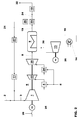
- Fig. 1 shows a schematic representation of the essential elements of a gas turbine power plant according to the invention.
- the gas turbine 6 comprises a compressor 1 (compressor), the combustion air compressed therein is fed to a combustion chamber 4 and burned there with fuel 5. Subsequently, the hot combustion gases are expanded in a turbine 7. The useful energy generated in the turbine 7 is then converted into electrical energy, for example with a first generator 25 arranged on the same shaft.
- the hot exhaust gases 8 emerging from the turbine 7 are used to optimally utilize the energy still contained therein in a heat recovery steam generator 9 (HRSG) to generate live steam 30 for a steam turbine 13 or for other systems.
- HRSG heat recovery steam generator 9
- the useful energy generated in the steam turbine 13 is converted into electrical energy, for example, with a second generator 26 arranged on the same shaft.
- the steam circuit 39 is simplified in the example and shown only schematically with a condenser 14 and feedwater line 16. Various pressure levels, feedwater pumps, etc. are not shown because they are not the subject of the invention.
- the exhaust gases from the heat recovery steam generator 9 are divided downstream of the heat recovery steam generator 9 in a flow divider 29 into a first partial exhaust stream 21 and a second partial exhaust gas stream 24.
- the first partial exhaust gas stream 21 is returned to the intake line of the gas turbine 6 and mixed there with ambient air 2.
- the non-recirculated second partial exhaust gas stream 24 is discharged via a chimney 32 to the environment.
- an exhaust fan 11 or controllable exhaust fan 11 may optionally be provided.
- the flow divider 29 is designed as a control element, which allows to close the inlet to the recirculation line in order to prevent the entry of fuel residues in the recirculation line.
- This recirculated exhaust gas flow 21 is mixed with the ambient air 2 before the mixture is supplied as intake flow via the compressor inlet 3 of the gas turbine 6.
- FIG. 1 shows a gas turbine 6 with simple combustion chamber 4.
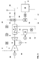
- the invention is also without limitation for gas turbines with sequential combustion, as for example from EP0718470 are known, applicable.
- FIG. 2 schematically an example of a gas turbine power plant with sequential combustion and exhaust gas recirculation is shown.
- the combustion chamber 4 is followed by a high-pressure turbine 33.
- the discharge gases of the high-pressure turbine 33 which are partially decompressed under work output, are supplied and combusted again in the second combustion chamber 34.
- the hot combustion gases of the second combustion chamber 34 are further relaxed in the low-pressure turbine 35 under work output.
- a control element 36 is provided in addition to the exhaust divider 29, which may be designed to be non-adjustable.
- a carbon dioxide separation system 18 is shown.
- the non-recirculated second partial exhaust gas stream 20 is typically further cooled in an exhaust gas recooler 23 and fed to the carbon dioxide separation system 18. From this low-carbon exhaust gases 22 are discharged through a chimney 32 to the environment.
- an exhaust fan 10 may be provided.
- the carbon dioxide 31 deposited in the carbon dioxide separation system 18 is typically compressed in a compressor (not shown) and discharged for storage or further treatment.
- the carbon dioxide removal system 18 is supplied via a steam extraction 15 with steam, typically medium or low pressure steam, which is diverted from the steam turbine 13.
- the steam is returned to the water vapor cycle after the energy has been released in the carbon dioxide separation system 18.
- the steam is condensed and fed via the condensate return line 17 to the feed water.
- the second partial exhaust gas stream can also be fed directly to the chimney 32 via an exhaust gas bypass 24, which comprises a bypass flap or valve.
Landscapes
- Engineering & Computer Science (AREA)
- Chemical & Material Sciences (AREA)
- Combustion & Propulsion (AREA)
- Mechanical Engineering (AREA)
- General Engineering & Computer Science (AREA)
- Life Sciences & Earth Sciences (AREA)
- Sustainable Development (AREA)
- Engine Equipment That Uses Special Cycles (AREA)
- Control Of Turbines (AREA)
Abstract
Description
- Die vorliegende Erfindung betrifft ein Verfahren und System zur Regelung des Starts einer Gasturbine mit Abgasrezirkulation sowie ein Gasturbinenkraftwerk zur Durchführung des Verfahrens.
- Die Rezirkulation von Abgasen ist eine Technologie, welche grundsätzlich für unterschiedlichste Zwecke bei Gasturbinen eingesetzt werden kann. So wird Abgasrezirkulation beispielsweise für die Reduktion der NOx- Emission oder zu einer Reduktion des abzuleitenden Abgases vorgeschlagen. Bei der Rezirkulation von Abgasen bei einer Gasturbine wird ein wesentlicher Anteil des Abgases aus dem gesamten Abgasstrom abgezweigt und typischerweise nach Kühlung und Reinigung dem Eingangsmassenstrom der Gasturbine respektive dem Kompressor zugeführt, wobei der rückgeführte Abgasstrom mit frischer Luft vermischt wird, und diese Mischung anschliessend dem Kompressor zugeführt wird.
- Vorteilhaft kann durch Abgasrezirkulation der Kohlendioxid- Partialdruck in den Abgasen erhöht werden, um die Leistungsverluste und Wirkungsgradverluste von Kraftwerken mit Kohlendioxid-Abscheidung zu reduzieren. Weiter ist Abgasrezirkulation mit dem Ziel vorgeschlagen worden, die Sauerstoffkonzentration in den Ansauggasen von Gasturbinen zu reduzieren, um dadurch die NOx- Emissionen zu reduzieren.
- Zur Abgasrezirkulation beschreibt beispielsweise die
US 7536252 B1 ein Verfahren zum Steuern eines Abgasrezirkulationsstroms einer Turbomaschine, der über ein Abgasrezirkulationssystem zu dem Eintritt der Turbomaschine zurückgeführt wird. In diesem Verfahren wird ein Soll- Abgasrezirkulationsanteil bestimmt, wobei der Abgasrezirkulationsanteil als Anteil des Abgasstroms an dem Eintrittsstrom der Turbomaschine definiert ist, und der Ist-Wert auf den Soll- Wert geregelt wird. - Aus der
US2009/0145126 ist eine Methode zum Betreiben einer Gasturbine mit Abgasrezirkulation bekannt, bei dem die Abgaszusammensetzung bestimmt wird, und ein Kontrollorgan das eine Regelung der Abgasrezirkulation in Abhängigkeit von der gemessenen Abgaszusammensetzung erlaubt, bekannt. Eine derartige Regelung kann insbesondere beim Start oder Betrieb mit schnellen Transienten im tiefen Lastbereich zu einer instabilen Regelung führen, da die Abgaszusammensetzung stark von dem Anteil an rezirkulierten Abgasen abhängt. Weiter ist die Abgaszusammensetzung, oder die zulässige Zusammensetzung der Eintrittsgase der Gasturbine stark von dem Betriebspunkt der Gasturbine abhängig, so dass ein zuverlässiger Betrieb der Gasturbine mit Abgasrezirkulation für bestimmte Betriebszustände erschwert wird. - Um sicher zu stellen, dass keine brennbaren oder explosiven Brennstoff- Luftgemische in den Rezirkulationsleitung zurückgeblieben sind, wird typischerweise vorgeschlagen, die Rezirkulationsleitungen vor dem Start einer Gasturbine zu spülen, wofür zusätzliche Klappen und Leitungen benötigt werden. Beispielsweise ist aus der
EP2060772 ein Purgesystem zum Spülen für ein Abgasrezirkulationssystem bekannt. - Der vorliegenden Erfindung ist die Aufgabe gestellt, ein Verfahren zum zuverlässigen Betrieb eines Gasturbinenkraftwerkes mit Abgasrezirkulation bei tiefer Last sowie zum Start und Abstellen der Gasturbine und der Abgasrezirkulation anzugeben.
- Erfindungsgemäss wird diese Aufgabe durch den Gegenstand der unabhängigen Ansprüche gelöst. Der Kern der Erfindung ist ein Verfahren zum Betrieb einer Gasturbine mit Abgasrezirkulation, bei welchem die Abgasrezirkulation während des Startens und des Abschaltens der Gasturbine ausgeschaltet ist, und bei dem das Einschalten bzw. Ausschalten der Abgasrezirkulation in Abhängigkeit von einem Betriebszustand der Gasturbine durchgeführt wird.
- insbesondere wird nach dem Verfahren bei einem Gasturbinenkraftwerk mit Abgasrezirkulation, welches eine Gasturbine einen Abhitzedampferzeuger und einen Abgasteiler, der die Abgase des Gasturbinenkraftwerkes in einen ersten Abgasstrom zur Rezirkulation in einen Ansaugstrom der Gasturbine und in einen zweiten Abgasstrom zur Abgabe an die Umgebung teilt, sowie ein Regelelement zur Regelung des ersten Abgasstroms umfasst, das Regelelement bis zum Überschreiten einer Einschaltlast in einer geschlossenen Position gehalten, so das keine Abgase in Rezirkulationsleitungen gelangen und der gesamte Abgasstrom des Gasturbinenkraftwerkes als zweiter Abgasstrom an die Umgebung abgegeben wird. Erst nach erreichen einer Freigabebedingung, beispielsweise dem Überschreiten einer Einschaltlast, wird nach dem Verfahren das Regelelement geöffnet, um einen Teil der Abgase als ersten Abgasstrom in den Ansaugstrom zu rezirkulieren. Als Freigabebedingung ist gemäss weiterer Ausführungen ein Druckgrenzwert, insbesondere der Brennkammer oder Verdichterenddruck, ein Limitwert der Heissgasgastemperatur oder ein Limit des Brennstoffmassenstrom bzw. der Position des Brennstoffregelventils vorgesehen.
- Je nach Start-up Prozedur der Gasturbine ist die Verbrennung während des Hochlaufen auf Nenndrehzahl instabil und zusätzliche Änderungen der Randbedingungen sind unerwünscht. Entsprechend einer Ausgestaltung des Verfahrens wird die Abgasrezirkulation daher erst ab erreichen der Nenndrehzahl eingeschaltet.
- Gemäss einer weiteren Ausgestaltung wird, um eine Kontamination der Abgasrezirkulationsleitungen mit Brennstoffrückständen zu vermeiden, die Abgasrezirkulation vor oder bei dem Abstellen der Gasturbine abgeschaltet.
- Gemäss einer Ausgestaltung wird die Abgasrezirkulation beim Ablasten nach unterschreiten einer Ausschaltbedingung abgeschaltet. Diese ist in einer weiteren Ausführung eine Ausschaltlast.
- Als Ausschaltbedingung ist gemäss weiterer Ausführungen ein Druckgrenzwert, insbesondere der Brennkammer oder Verdichterenddruck, ein Limitwert der Heissgasgastemperatur oder ein Limit des Brennstoffmassenstroms bzw. der Position des Brennstoffregelventils vorgesehen.
- Insbesondere wird bei der Abzweigung der Abgasrezirkulationsleitungen von der Abgasleitung ein Regelelement vorgesehen, das schliesst, bevor Brennstoffrückstände in die Abgasrezirkulationsleitungen gelangen.
- Da die Abgasrezirkulation durch Gebläse und Kühler Hilfsenergie verbraucht, wird in einer Ausführung die Abgasrezirkulation erst ab Generatorsynchronisation oder ab einem bestimmten Lastpunkt vorgesehen. Entsprechend wird die Abgasrezirkulation unterhalb eines definierten Lastpunktes, d.h. unterhalb einer Ausschaltlast ausgeschaltet. Beim Ablasten wird unterhalb dieser Ausschaltlast der gesamte Abgasstrom des Gasturbinenkraftwerkes als zweiter Abgasstrom an die Umgebung abgegeben. Nach einer Ausführung wird die Abgasrezirkulation erst beim Öffnen des Generatorschalters ausgeschaltet.
- In einer Ausgestaltung des Verfahrens ist die Ausschaltbedingung kleiner als die Einschaltbedingung. Beispielsweise ist Ausschaltlast kleiner als Einschaltlast, um ein häufiges Ein- und Ausschalten der Abgasrezirkulation bei tiefer Teillast zu vermeiden.
- Gemäss einer weiteren Ausführung des Verfahren ist die Einschaltlast kleiner oder gleich der Minimallast der Gasturbine. Sobald der Generator der Gasturbine mit dem Netz synchronisiert ist und der Generatorschalter geschlossen ist, wird in diesem Verfahren das Regelelement der Abgasrezirkulation geöffnet, um einen Teil der Abgase als ersten Abgasstrom in den Ansaugstrom zu rezirkulieren.
- Nach einer weiteren Ausführung wird das Regelelement der Abgasrezirkulation beim Öffnen des Generatorschalters geschlossen. Hier wird der gesamte Abgasstrom des Gasturbinenkraftwerkes als zweiter Abgasstrom an die Umgebung abgegeben, sobald der Generatorschalter öffnet.
- Bei niedriger Last eines Gasturbinenkraftwerkes können tiefe Heissgastemperaturen zu unvollständiger Verbrennung führen und CO- Emissionen (Kohlenmonoxidemissionen) ansteigen. Um eine weitere Erhöhung der CO- Emissionen durch Abgasrezirkulation, die zu sauerstoffarmen Brenngasen führt, zu vermeiden, wird die Abgasrezirkulation in einer Ausführungsform erst ab einer Last aktiviert, bei der das Kraftwerk längere Zeit stationär betrieben wird. Dies ist typischerweise etwa 20 bis 30% relative Last. Bei dieser Last kann das Kraftwerk mit einem ausreichenden Wirkungsgrad betrieben werden und die Heissgastemperaturen sind hoch genug, um eine saubere Verbrennung mit Abgasrezirkulation zu erlauben.
- Je nach Gasturbinentyp kann der Grenzwert für die Aktivierung der Abgasrezirkulation bei bis zu 50% oder 60% relative Last liegen, wobei die relative Last als das Verhältnis von abgegebener Leistung zu der möglichen Vollastleistung bei den jeweiligen Umgebungsbedingungen definiert ist.
- Bei einem Abschalten einer Gasturbine können Brennstoffreste in die Abgase gelangen. Wenn die Abgasrezirkulation offen ist, können diese Brennstoffreste auch in die Rezirkulationsleitungen gelangen, die dann vor einem Neustart der Gasturbine aufwändig mit Luft oder einem anderen Gas gespült werden müssen. Um diese Verunreinigung und den Spülvorgang zu vermeiden, wird nach einer Ausführung des Verfahrens das Regelelement schneller geschlossen, als Abgase benötigen, um von der Turbine durch den HRSG zu strömen und zu dem Abgasteiler zu gelangen. Durch ein entsprechend schnelles Schliessen wird verhindert, dass Brennstoffreste in das Abgasrezirkulationssystem gelangen. Ein Spülen des Systems ist somit für einen Neustart nicht erforderlich.
- Eine Gasturbine umfast typischerweise einen Verdichter, eine Brennkammer und eine Turbine, die den Verdichter antreibt und nutzbare Leistung abgibt. In einer weiteren Ausführung des Verfahrens, das für die Anwendung in Gasturbinen mit sequentieller Verbrennung, d.h. eine Gasturbine mit einem Verdichter, einer ersten Brennkammer, einer Hochdruckturbine, einer zweiten Brennkammer (sequentieller Brennkammer) und einer Niederdruckturbine, vorgesehen ist, wird vor oder bei einem Ausschalten der zweiten Brennkammer das Regelelement zur Regelung des Rezirkulationsstroms geschlossen. Die zweite Brennkammer wird typischerweise bei Teillast abgeschaltet, während die erste Brennkammer weiter in Betrieb bleibt, um eine stabile saubere Verbrennung zu gewährleisten. Wenn die Eintrittstemperatur in die zweite Brennkammer bei tiefer Teillast niedrig ist, kann beim Abschalten der zweiten Brennkammer unverbrannter Brennstoff die Brennkammer und damit die Niederdruckturbine verlassen. Dies kann beispielsweise bei einem Lastabwurf aus Ölbetrieb geschehen, wenn nach Abschalten der Brennkammer noch die Brennstoffleitungen in den Brenner gespült werden. Um zu verhindern, dass Brennstoffrückstände über die Rezirkulationsleitung in den Verdichtereintritt der Gasturbine gelangen, wird das Regelelement der Rezirkulation vor Abschalten der zweiten Brennkammer geschlossen. Alternativ wird das Regelelement bei oder kurz nach dem Abschalten der zweiten Brennkammer so schnell geschlossen, dass eventuelle Brennstoffrückstände bis zu deren Schliessen noch nicht den Weg von der Brennkammer zu dem Regelelement zurückgelegt haben.
- Gemäss einer weiteren Ausführungsform wird das Regelelement zum Regeln der Rezirkulation vor einem Spülen der Ölleitungen des Brennstoffverteilsystems der zweiten Brennkammer geschlossen, damit während des Spülvorganges der gesamte Abgasstrom des Gasturbinenkraftwerkes als zweiter Abgasstrom an die Umgebung abgegeben wird. Nach Abschluss des Spülvorganges kann das Regelelement wieder geöffnet werden und ein Teil der Abgase in den Eintritt der Gasturbine rezirkuliert werden.
- Neben dem Verfahren ist ein Gasturbinenkraftwerk zur Durchführung des Verfahrens mit Abgasrezirkulation Gegenstand der Erfindung. Ein derartiges Kraftwerk umfasse eine Gasturbine mit einem Regler, einen Abhitzedampferzeuger und einen Abgasteiler, der die Abgase in einen ersten Abgasstrom zur Rezirkulation in einen Ansaugstrom der Gasturbine und in einen zweiten Abgasstrom zur Abgabe an die Umgebung teilt, sowie ein Regelelement zur Regelung des ersten Abgasstroms umfasst. Dieses Kraftwerk ist zeichnet sich dadurch aus, dass das Regelelement zur Regelung des ersten Abgasstroms in einer Zeit schliessbar ist, die kleiner ist als die Zeit, die Abgase benötigen, um vom Turbineaustritt durch den HRSG bis zu dem Regelelement zu strömen. Typischerweise muss das Regelelement dafür in weniger als 30 Sekunden schliessen können. Die erforderliche Schliesszeit ergibt sich aus dem Abgasvolumenstrom und dem Volumen von Kessel und Abgasleitungen zwischen Gasturbine und Abgasteiler. Die Schliesszeit kann beispielsweise sogar in weniger als 10 Sekunden betragen.
- In einem Ausführungsbeispiel wird, um ein schnellen Schliessen der Rezirkulationsleitung zu gewährleisten, zusätzlich zu dem Regelelement zur Regelung des ersten Abgasstroms ein Schnellschlussventil oder eine Schnellschlussklappe im Eintrittsbereich der Rezirkulationsleitung, vorgesehen. Dies ist bei Rezirkulationsleitungen mit grossen Querschnittsflächen vorteilhaft, da die verfügbaren Regelelemente typischerweise nur langsam Fahren können und ein separates Schnellschlussventil günstiger sein kann, als ein Regelelement mit der erforderlichen Schliessgeschwindigkeit bereit zu stellen. Typischerweise kann die Schnellschlussklappe oder das Schnellschlussventil in weniger als 30 Sekunden schliessen. Sie kann beispielsweise sogar in weniger als 10 Sekunden schliessen. Als Eintrittsbereich der Rezirkulationsleitung ist der Bereich zu verstehen, der unmittelbar an den Strömungsteiler anschliesst. Vorzugsweise sollte das Schnellschlussventil in einer Entfernung von dem Strömungsteiler angeordnet sein, die kleiner als der zwei- bis dreifachen Durchmesser der Rezirkulationsleitung ist.
- Falls kein separates Schnellschlussventil vorgehen wird, wird das Regelelement vorzugsweise im Eintrittsbereich der Rezirkulationsleitung angeordnet.
- Alle erläuterten Vorteile sind nicht nur in den jeweils angegebenen Kombinationen, sondern auch in anderen Kombinationen oder Alleinstellung verwendbar, ohne den Rahmen der Erfindung zu verlassen. Beispielsweise kann anstelle der Verwendung eines Regelelementes, das ein Schliessen der Rezirkulationsleitung erlaubt, wie eine regelbare Klappe oder ein Ventil, auch ein regelbares Abgasgebläse oder ein Booster als Regelelement vorgesehen werden, dass mit einem Schnellschlussventil kombiniert wird. Vereinfachend ist allgemein die Regelung des Regelelementes beschrieben worden. Diese steht stellvertretend für Regelung oder Steuerung. Dem Fachmann sind verschiedene Regelstrategien, wie Zweipunktregelung, Regelung mit Proportionalregler, Integral- oder IP- Regler bekannt. Weiter sind dem Fachmann verschiedene Reinigungs- und Aufbereitungsmethoden für die rezirkulierten Abgase, wie z.B. eine Gaswäsche, bekannt.
- Bevorzugte Ausführungsformen der Erfindung werden im Folgenden anhand der Zeichnungen beschrieben, die lediglich zur Erläuterung dienen und nicht einschränkend auszulegen sind. In den Zeichnungen zeigen:
- Fig. 1
- eine schematische Darstellung eines Gasturbinenkraftwerks mit Rückführung der Abgase;
- Fig. 2
- eine schematische Darstellung eines Gasturbinenkraftwerks mit einer Gasturbine mit sequentieller Verbrennung und Rückführung der Abgase; und
- Fig. 3
- eine schematische Darstellung eines Gasturbinenkraftwerks mit einer Gasturbine mit sequentieller Verbrennung und Rückführung der Abgase und einem Kohlendioxid- Abscheidsystem.
-
Fig. 1 zeigt in schematischer Darstellung die wesentlichen Elemente eines erfindungsgemässen Gasturbinenkraftwerks. Die Gasturbine 6 umfasst einen Verdichter 1 (Kompressor), die darin verdichtete Verbrennungsluft wird einer Brennkammer 4 zugeführt und dort mit Brennstoff 5 verbrannt. Anschliessend werden die heissen Verbrennungsgase in einer Turbine 7 entspannt. Die in der Turbine 7 erzeugte Nutzenergie wird dann zum Beispiel mit einem auf der gleichen Welle angeordneten ersten Generator 25 in elektrische Energie umgewandelt. - Die aus der Turbine 7 austretenden heissen Abgase 8 werden zur optimalen Nutzung der darin noch enthaltenen Energie in einem Abhitzedampferzeuger 9 (Heat recovery steam generator, HRSG) dazu verwendet, Frischdampf 30 für eine Dampfturbine 13 oder für andere Anlagen zu erzeugen. Die in der Dampfturbine 13 erzeugte Nutzenergie wird zum Beispiel mit einem auf der gleichen Welle angeordneten zweiten Generator 26 in elektrische Energie umgewandelt. Der Wasserdampfkreislauf 39 ist in dem Beispiel vereinfacht und nur schematisch mit einem Kondensator 14 und Speisewasserleitung 16 dargestellt. Verschiedene Druckstufen, Speisewasserpumpen usw. werden nicht gezeigt, da diese nicht Gegenstand der Erfindung sind.
- Die Abgase vom Abhitzedampferzeuger 9 werden stromab des Abhitzedampferzeugers 9 in einem Strömungsteiler 29 in einen ersten Abgasteilstrom 21 und einen zweiten Abgasteilstrom 24 geteilt. Der erste Abgasteilstrom 21 wird in die Ansaugleitung der Gasturbine 6 zurückgeführt und dort mit Umgebungsluft 2 vermischt. Der nicht zurückgeführte zweite Abgasteilstrom 24 wird über einen Kamin 32 an die Umgebung abgegeben. Um die Druckverluste der Abgasleitung zu überwinden und als weitere Regelmöglichkeit der Aufteilung der Abgasströme, kann optional ein Abgasgebläse 11 oder regelbares Abgasgebläse 11 vorgesehen sein.
- In dem gezeigten Beispiel ist der Strömungsteiler 29 als Regelelement ausgeführt, das es erlaubt, den Eintritt in die Rezirkulationsleitung zu schliessen, um den Eintritt von Brennstoffrückständen in die Rezirkulationsleitung zu verhindern.
- Im Betrieb mit Rezirkulation wird der zurückgeführte Abgasstrom 21 in einem Abgasrückkühler 27, welcher mit Kondensator ausgestattet sein kann, auf etwas über Umgebungstemperatur abgekühlt. Stromab dieses Abgasrückkühlers 27 kann ein Booster oder Abgasgebläse 11 für den Rezirkulationsstrom 21 angeordnet sein. Dieser zurückgeführte Abgasstrom 21 wird mit der Umgebungsluft 2 vermischt, bevor das Gemisch als Ansaugstrom über den Verdichter- Eintritt 3 der Gasturbine 6 zugeführt wird.
- Das Beispiel in
Fig. 1 zeigt eine Gasturbine 6 mit einfacher Brennkammer 4. Die Erfindung ist ohne Einschränkung auch für Gasturbinen mit sequentieller Verbrennung, wie sie beispielsweise aus derEP0718470 bekannt sind, anwendbar. InFig. 2 ist schematisch ein Beispiel für ein Gasturbinenkraftwerk mit sequentieller Verbrennung und Abgasrezirkulation gezeigt. Bei dieser Gasturbine folgt der Brennkammer 4 eine Hochdruckturbine 33. Den unter Arbeitsabgabe teilentspannten Austrittsgasen der Hochdruckturbine 33 wird in der zweiten Brennkammer 34 nochmals Brennstoff 5 zugeführt und verbrannt. Die heissen Verbrennungsgase der zweiten Brennkammer 34 werden in der Niederdruckturbine 35 unter Arbeitsabgabe weiter entspannt. Die Nutzung der Abwärme sowie Rezirkulation erfolgen analog dem Ausführungsbeispiel ausFig. 1 . Zur Regelung und Absperrung des Rezirkulationsstroms ist zusätzlich zu dem Abgasteiler 29, der unverstellbar ausgeführt sein kann, noch ein Regelelement 36 vorgesehen. - In der
Fig. 3 ist basierend auf derFig. 1 zusätzlich noch ein Kohlendioxid Abscheidsystem 18 dargestellt. Der nicht zurückgeführte zweite Abgasteilstrom 20 wird typischerweise in einem Abgasrückkühler 23 weiter gekühlt und dem Kohlendioxid Abscheidsystem 18 zugeführt. Von diesem werden Kohlendioxid- arme Abgase 22 über einen Kamin 32 an die Umgebung abgegeben. Um die Druckverluste des Kohlendioxid- Abscheidsystems 18 und der Abgasleitung zu überwinden, kann ein Abgasgebläse 10 vorgesehen sein. Das in dem Kohlendioxid- Abscheidsystem 18 abgeschiedene Kohlendioxid 31 wird typischerweise in einem Verdichter (nicht gezeigt) komprimiert und zur Lagerung oder weiteren Behandlung abgeleitet. Das Kohlendioxid- Abscheidsystem 18 ist über eine Dampfextraktion 15 mit Dampf, typischerweise Mittel- oder Niederdruckdampf, der aus der Dampfturbine 13 abgezweigt wird, versorgt. Der Dampf wird dem Wasserdampfkreislauf nach Energieabgabe im Kohlendioxid- Abscheidsystem 18 wieder zurückgeführt. In dem gezeigten Beispiel wird der Dampf kondensiert und über die Kondensatrückführleitung 17 dem Speisewasser zugeführt. - Der zweite Abgasteilstrom kann auch direkt über einen Abgasbypass 24, der eine Bypassklappe oder Ventil umfasst, zu dem Kamin 32 geführt werden.
- Zusätzlich zu den in
Fig. 1 gezeigtem Ausführungsbeispiel umfasst das Abgasrezirkulationssystem des inFig. 3 gezeigten Beispiels noch ein separates Regelelement 36 zur Regelung des Rezirkulationsstroms und ein Schnellschlussventil oder eine Schnellschlussklappe 37 -
- 1
- Verdichter
- 2
- Umgebungsluft
- 3
- Verdichter-Eintritt
- 4
- Brennkammer, erste Brennkammer
- 5
- Brennstoff
- 6
- Gasturbine
- 7
- Turbine
- 8
- Heisse Abgase der Gasturbine
- 9
- Abhitzedampferzeuger (heat recovery steam generator, HRSG)
- 10
- Abgasgebläse für den zweiten partiellen Abgasstrom (zum Kohlendioxid-Abscheide- System oder Kamin)
- 11
- Abgasgebläse für den ersten Abgasteilstrom (Abgasrezirkulation)
- 12
- Bypassklappe oder Ventil
- 13
- Dampfturbine
- 14
- Kondensator
- 15
- Dampfextraktion für das Kohlendioxid- Abscheidsystem
- 16
- Speisewasserleitung
- 17
- Kondensat Rückführleitung
- 18
- Kohlendioxid- Abscheidsystem
- 19
- Abgas vom Abhitzedampferzeuger
- 20
- Zweiter Abgasteilstrom (Abgasleitung zum Kohlendioxid- Abscheidsystem)
- 21
- Erster Abgasteilstrom (Abgasrezirkulation)
- 22
- Kohlendioxidarmes Abgas
- 23
- Abgasrückkühler (für den zweiten Abgasteilstrom)
- 24
- Abgasbypass zum Kamin
- 25
- Erster Generator
- 26
- Zweiter Generator
- 27
- Abgasrückkühler (für den ersten Abgasteilstrom)
- 28
- Generatorschalter
- 29
- Abgasteiler
- 30
- Frischdampf
- 31
- Abgeschiedenes Kohlendioxid
- 32
- Kamin
- 33
- Hochdruckturbine
- 34
- zweite Brennkammer
- 35
- Niederdruckturbine
- 36
- Regelelement
- 37
- Schnellschlussventil oder Schnellschlussklappe
- Pon
- Einschaltlast
- Poff
- Ausschaltlast
Claims (13)
- Verfahren zum Betrieb eines Gasturbinenkraftwerkes mit Abgasrezirkulation, welches eine Gasturbine (6), einen Abhitzedampferzeuger (9) und einen Abgasteiler (29), der die Abgase (19) des Gasturbinenkraftwerkes in einen ersten Abgasstrom (21) zur Rezirkulation in einen Ansaugstrom der Gasturbine (6) und in einen zweiten Abgasstrom (24) zur Abgabe an die Umgebung teilt, sowie ein Regelelement (11, 29) zur Regelung des ersten Abgasstroms (21) umfasst, dadurch gekennzeichnet, dass das Regelelement (11, 29) bis zum Erreichen einer Freigabebedingung in einer geschlossenen Position bleibt, in der der gesamte Abgasstrom (19) des Gasturbinenkraftwerkes als zweiter Abgasstrom (24) an die Umgebung abgegeben wird und erst nach Erreichen der Freigabebedingung öffnet, um einen Teil der Abgase (19) als ersten Abgasstrom (21) in den Ansaugstrom zu rezirkulieren.
- Verfahren nach Anspruch 1, dadurch gekennzeichnet, dass die Freigabebedingung das Überschreiten einer Einschaltlast (Pon) ist und das Regelelement (11, 29) zur Regelung des ersten Abgasstroms (21) erst nach Überschreiten der Einschaltlast (Pon) öffnet, um einen Teil der Abgase (19) als ersten Abgasstrom (21) in den Ansaugstrom zu rezirkulieren.
- Verfahren nach Anspruch 1 oder 2, dadurch gekennzeichnet, dass das Regelelement (11, 29) bei Unterschreiten einer Ausschaltbedingung geschlossen wird, und der gesamte Abgasstrom (19) des Gasturbinenkraftwerkes als zweiter Abgasstrom (24) an die Umgebung abgegeben wird.
- Verfahren nach Anspruch 3, dadurch gekennzeichnet, dass die Ausschaltbedingung das Unterschreiten einer Ausschaltlast (Poff) ist.
- Verfahren nach Anspruch 4, dadurch gekennzeichnet, dass die Ausschaltlast (Poff) kleiner als Einschaltlast (Pon) ist.
- Verfahren nach Anspruch 2, dadurch gekennzeichnet, dass die Einschaltlast (Pon) kleiner oder gleich der Minimallast der Gasturbine (6) ist und sobald der Generator (25) der Gasturbine (6) mit dem Netz synchronisiert ist und der Generatorschalter (28) geschlossen ist das Regelelement (11, 29) öffnet, um einen Teil der Abgase (19) als ersten Abgasstrom (21) in den Ansaugstrom zu rezirkulieren.
- Verfahren nach einem der Ansprüche 1 bis 6, dadurch gekennzeichnet, dass das Regelelement (11, 29) beim Öffnen des Generatorschalters (28) geschlossen wird, und der gesamte Abgasstrom (19) des Gasturbinenkraftwerkes als zweiter Abgasstrom (24) an die Umgebung abgegeben wird.
- Verfahren nach einem der Ansprüche 1 bis 7, dadurch gekennzeichnet, dass das Regelelement (11, 29) schneller geschlossen wird, als Abgas, das aus der Turbine (7) austritt, benötigt, um durch den HRSG (9) zu strömen.
- Verfahren zum Betrieb eines Gasturbinenkraftwerkes mit Abgasrezirkulation nach einem der Ansprüche 1 bis 8, dadurch gekennzeichnet, dass die Gasturbine eine erste und eine zweite Brennkammer umfasst, und dass das Regelelement (11, 29) vor oder bei einem Abschalten der zweiten Brennkammer geschlossen wird damit der gesamte Abgasstrom (19) des Gasturbinenkraftwerkes als zweiter Abgasstrom (24) an die Umgebung abgegeben wird.
- Verfahren zum Betrieb eines Gasturbinenkraftwerkes mit Abgasrezirkulation nach einem der Ansprüche 1 bis 8, dadurch gekennzeichnet, dass im Ölbetrieb der Gasturbine das Regelelement (11, 29) vor einem Spülen der Ölleitungen des Brennstoffverteilsystems der Brennkammer (4) geschlossen wird, damit während des Spülvorganges der gesamte Abgasstrom (19) des Gasturbinenkraftwerkes als zweiter Abgasstrom (24) an die Umgebung abgegeben wird.
- Verfahren zum Betrieb eines Gasturbinenkraftwerkes mit Abgasrezirkulation nach einem der Ansprüche 1 bis 8, dadurch gekennzeichnet, dass die Gasturbine eine erste und eine zweite Brennkammer umfasst, und dass im Ölbetrieb der Gasturbine das Regelelement (11, 29) vor einem Spülen der Ölleitungen des Brennstoffverteilsystems der zweiten Brennkammer (34) geschlossen wird, damit während des Spülvorganges der gesamte Abgasstrom (19) des Gasturbinenkraftwerkes als zweiter Abgasstrom (24) an die Umgebung abgegeben wird.
- Gasturbinenkraftwerk mit Abgasrezirkulation, welches eine Gasturbine (6) mit einem Regler, einen Abhitzedampferzeuger (9) und einen Abgasteiler (29), der die Abgase (19) in einen ersten Abgasstrom (21) zur Rezirkulation in einen Ansaugstrom der Gasturbine (6) und in einen zweiten Abgasstrom (24) zur Abgabe an die Umgebung teilt, sowie ein Regelelement (29, 36) zur Regelung des ersten Abgasstroms (21) umfasst, dadurch gekennzeichnet, dass das Regelelement (29, 36) eine Schliessgeschwindigkeit hat, die so gross ist, dass das Regelelement (36) in einer Zeit schliessbar ist, die kleiner ist als die Zeit, die Abgase benötigen, um von der Turbine (7, 35) durch den HRSG (9) zu strömen und zu dem Abgasteiler (29) zu gelangen.
- Gasturbinenkraftwerk mit Abgasrezirkulation, welches eine Gasturbine (6) mit einem Regler, einen Abhitzedampferzeuger (9) und einen Abgasteiler (29), der die Abgase (19) in einen ersten Abgasstrom (21) zur Rezirkulation in einen Ansaugstrom der Gasturbine (6) und in einen zweiten Abgasstrom (24) zur Abgabe an die Umgebung teilt, sowie ein Regelelement (29, 36) zur Regelung des ersten Abgasstroms (21) umfasst, dadurch gekennzeichnet, dass im Anschlussbereich der Rezirkulationsleitung ein Schnellschlussventil oder eine Schnellschlussklappe (37) vorgesehen ist.
Applications Claiming Priority (1)
| Application Number | Priority Date | Filing Date | Title |
|---|---|---|---|
| CH7212011 | 2011-04-28 |
Publications (2)
| Publication Number | Publication Date |
|---|---|
| EP2518292A1 true EP2518292A1 (de) | 2012-10-31 |
| EP2518292B1 EP2518292B1 (de) | 2018-01-10 |
Family
ID=44223537
Family Applications (1)
| Application Number | Title | Priority Date | Filing Date |
|---|---|---|---|
| EP12166079.9A Active EP2518292B1 (de) | 2011-04-28 | 2012-04-27 | Verfahren zum Betrieb eines Gasturbinenkraftwerks mit Abgasrezirkulation |
Country Status (4)
| Country | Link |
|---|---|
| US (1) | US9097187B2 (de) |
| EP (1) | EP2518292B1 (de) |
| JP (1) | JP5840559B2 (de) |
| CN (1) | CN102767431B (de) |
Cited By (1)
| Publication number | Priority date | Publication date | Assignee | Title |
|---|---|---|---|---|
| CN109026402A (zh) * | 2018-09-25 | 2018-12-18 | 杭州螺旋新能源科技有限公司 | 一种燃气轮机的启动方法及启动装置 |
Families Citing this family (6)
| Publication number | Priority date | Publication date | Assignee | Title |
|---|---|---|---|---|
| TWI593878B (zh) * | 2010-07-02 | 2017-08-01 | 艾克頌美孚上游研究公司 | 用於控制燃料燃燒之系統及方法 |
| US9915200B2 (en) * | 2014-01-21 | 2018-03-13 | General Electric Company | System and method for controlling the combustion process in a gas turbine operating with exhaust gas recirculation |
| EP3425177B1 (de) * | 2017-07-05 | 2020-03-25 | Ansaldo Energia Switzerland AG | Verfahren zum starten eines kombikraftwerks |
| JP7330718B2 (ja) | 2019-02-28 | 2023-08-22 | 三菱重工業株式会社 | ガスタービンプラント、及びその排出二酸化炭素回収方法 |
| JP2021191951A (ja) * | 2020-06-05 | 2021-12-16 | 東芝エネルギーシステムズ株式会社 | Co2タービン発電システム |
| EP4612402A1 (de) * | 2022-12-26 | 2025-09-10 | General Electric Technology GmbH | Systeme zur stabilisierung der gasturbinenmotorleistung während netzereignissen |
Citations (10)
| Publication number | Priority date | Publication date | Assignee | Title |
|---|---|---|---|---|
| EP0718470A2 (de) | 1994-12-24 | 1996-06-26 | ABB Management AG | Verfahren zum Betrieb einer Gasturbogruppe |
| DE102004039164A1 (de) * | 2004-08-11 | 2006-03-02 | Alstom Technology Ltd | Verfahren zur Erzeugung von Energie in einer eine Gasturbine umfassenden Energieerzeugungsanlage sowie Energieerzeugungsanlage zur Durchführung des Verfahrens |
| WO2008155242A1 (de) * | 2007-06-19 | 2008-12-24 | Alstom Technology Ltd | Gasturbinenanlage mit abgasrezirkulation |
| US7536252B1 (en) | 2007-12-10 | 2009-05-19 | General Electric Company | Method and system for controlling a flowrate of a recirculated exhaust gas |
| EP2060772A2 (de) | 2007-11-14 | 2009-05-20 | General Electric Company | Reinigungssystem für ein Abgas-Rückführungssystem |
| US20090129914A1 (en) * | 2007-11-16 | 2009-05-21 | General Electric Company | Auxiliary fluid source for an egr purge system |
| US20090145126A1 (en) | 2007-12-10 | 2009-06-11 | General Electric Company | Method and system for controlling an exhaust gas recirculation system |
| US20090229263A1 (en) * | 2008-03-11 | 2009-09-17 | General Electric Company | Method for controlling a flowrate of a recirculated exhaust gas |
| WO2010049277A1 (de) * | 2008-10-29 | 2010-05-06 | Alstom Technology Ltd. | Gasturbinenanlage mit abgasrückführung sowie verfahren zum betrieb einer solchen anlage |
| WO2010139724A1 (de) * | 2009-06-02 | 2010-12-09 | Alstom Technology Ltd. | Gasturbine mit schmelzkarbonatbrennstoffzelle |
Family Cites Families (11)
| Publication number | Priority date | Publication date | Assignee | Title |
|---|---|---|---|---|
| US3785145A (en) * | 1971-11-10 | 1974-01-15 | Gen Motors Corp | Gas turbine power plant |
| JP2954456B2 (ja) * | 1993-07-14 | 1999-09-27 | 株式会社日立製作所 | 排気再循環型コンバインドプラント |
| US5953902A (en) * | 1995-08-03 | 1999-09-21 | Siemens Aktiengesellschaft | Control system for controlling the rotational speed of a turbine, and method for controlling the rotational speed of a turbine during load shedding |
| JP3794168B2 (ja) * | 1997-06-27 | 2006-07-05 | 株式会社日立製作所 | 排気再循環型コンバインドプラント |
| JP2007182785A (ja) | 2006-01-05 | 2007-07-19 | Mitsubishi Heavy Ind Ltd | ガスタービン及びガスタービンの起動方法並びに複合発電システム |
| US7861511B2 (en) * | 2007-10-30 | 2011-01-04 | General Electric Company | System for recirculating the exhaust of a turbomachine |
| US8352148B2 (en) * | 2008-05-21 | 2013-01-08 | General Electric Company | System for controlling input profiles of combined cycle power generation system |
| US9297306B2 (en) * | 2008-09-11 | 2016-03-29 | General Electric Company | Exhaust gas recirculation system, turbomachine system having the exhaust gas recirculation system and exhaust gas recirculation control method |
| US8015822B2 (en) * | 2008-11-21 | 2011-09-13 | General Electric Company | Method for controlling an exhaust gas recirculation system |
| EP2248999A1 (de) * | 2008-12-24 | 2010-11-10 | Alstom Technology Ltd | Kraftwerk mit CO2-Abscheidung |
| EP2246532A1 (de) * | 2008-12-24 | 2010-11-03 | Alstom Technology Ltd | Kraftwerk mit CO2-Abscheidung |
-
2012
- 2012-04-20 JP JP2012096411A patent/JP5840559B2/ja not_active Expired - Fee Related
- 2012-04-27 EP EP12166079.9A patent/EP2518292B1/de active Active
- 2012-04-27 CN CN201210195222.4A patent/CN102767431B/zh active Active
- 2012-04-30 US US13/459,811 patent/US9097187B2/en not_active Expired - Fee Related
Patent Citations (10)
| Publication number | Priority date | Publication date | Assignee | Title |
|---|---|---|---|---|
| EP0718470A2 (de) | 1994-12-24 | 1996-06-26 | ABB Management AG | Verfahren zum Betrieb einer Gasturbogruppe |
| DE102004039164A1 (de) * | 2004-08-11 | 2006-03-02 | Alstom Technology Ltd | Verfahren zur Erzeugung von Energie in einer eine Gasturbine umfassenden Energieerzeugungsanlage sowie Energieerzeugungsanlage zur Durchführung des Verfahrens |
| WO2008155242A1 (de) * | 2007-06-19 | 2008-12-24 | Alstom Technology Ltd | Gasturbinenanlage mit abgasrezirkulation |
| EP2060772A2 (de) | 2007-11-14 | 2009-05-20 | General Electric Company | Reinigungssystem für ein Abgas-Rückführungssystem |
| US20090129914A1 (en) * | 2007-11-16 | 2009-05-21 | General Electric Company | Auxiliary fluid source for an egr purge system |
| US7536252B1 (en) | 2007-12-10 | 2009-05-19 | General Electric Company | Method and system for controlling a flowrate of a recirculated exhaust gas |
| US20090145126A1 (en) | 2007-12-10 | 2009-06-11 | General Electric Company | Method and system for controlling an exhaust gas recirculation system |
| US20090229263A1 (en) * | 2008-03-11 | 2009-09-17 | General Electric Company | Method for controlling a flowrate of a recirculated exhaust gas |
| WO2010049277A1 (de) * | 2008-10-29 | 2010-05-06 | Alstom Technology Ltd. | Gasturbinenanlage mit abgasrückführung sowie verfahren zum betrieb einer solchen anlage |
| WO2010139724A1 (de) * | 2009-06-02 | 2010-12-09 | Alstom Technology Ltd. | Gasturbine mit schmelzkarbonatbrennstoffzelle |
Cited By (1)
| Publication number | Priority date | Publication date | Assignee | Title |
|---|---|---|---|---|
| CN109026402A (zh) * | 2018-09-25 | 2018-12-18 | 杭州螺旋新能源科技有限公司 | 一种燃气轮机的启动方法及启动装置 |
Also Published As
| Publication number | Publication date |
|---|---|
| JP2012233472A (ja) | 2012-11-29 |
| US20120291445A1 (en) | 2012-11-22 |
| CN102767431A (zh) | 2012-11-07 |
| US9097187B2 (en) | 2015-08-04 |
| EP2518292B1 (de) | 2018-01-10 |
| CN102767431B (zh) | 2016-08-24 |
| JP5840559B2 (ja) | 2016-01-06 |
Similar Documents
| Publication | Publication Date | Title |
|---|---|---|
| EP2518292B1 (de) | Verfahren zum Betrieb eines Gasturbinenkraftwerks mit Abgasrezirkulation | |
| DE102012019354B4 (de) | Verfahren zum Betrieb eines Gasturbinenkraftwerks mit Abgasrezirkulation | |
| EP2503106B1 (de) | Verfahren zum Betrieb eines Gasturbinenkraftwerks mit Abgasrezirkulation und sauerstoffarmen Kühlgas | |
| EP1914407B1 (de) | Verfahren zum Betrieb einer Gasturbinenanlage | |
| EP1432889B1 (de) | Verfahren und vorrichtung zum anfahren von emissionsfreien gasturbinenkraftwerken | |
| EP2831394B1 (de) | Gasturbine mit regelbarem kühlluftsystem | |
| CH703770A1 (de) | Verfahren zum spülen der abgasrezirkulationsleitungen einer gasturbine. | |
| DE10228335B3 (de) | Abhitzedampferzeuger mit Hilfsdampferzeugung | |
| EP2551487A1 (de) | Verfahren zum Betrieb eines Gasturbinenkraftwerks mit Abgasrezirkulation | |
| CH704381A1 (de) | Verfahren zum Betrieb eines Gasturbinenkraftwerks mit Abgasrezirkulation sowie Gasturbinenkraftwerk mit Abgasrezirkulation. | |
| CH701803A1 (de) | Gasturbogruppe und Verfahren zum Betrieb einer solchen Gasturbogruppe. | |
| CH698467B1 (de) | Vorrichtung und Verfahren zum Anfahren eines Kraftwerkes. | |
| DE10042317A1 (de) | Dampfturbine und Verfahren zur Einleitung von Beipassdampf | |
| EP2907980A1 (de) | Verfahren zum Betrieb einer Gas- und Dampfturbinenanlage für die Frequenzstützung | |
| EP1866521B1 (de) | Verfahren zum starten einer gas- und dampfturbinenanlage | |
| EP2556218B1 (de) | Verfahren zum schnellen zuschalten eines dampferzeugers | |
| WO2010139724A1 (de) | Gasturbine mit schmelzkarbonatbrennstoffzelle | |
| DE112006002967B4 (de) | Restdampf-Abführmechanismus und Restdampf-Abführverfahren für eine Dampfkühlleitung einer Gasturbine | |
| DE10052844B4 (de) | Verfahren und Vorrichtung zur Energiegewinnung aus Gas | |
| DE10205972A1 (de) | Verfahren zum Betrieb einer Gasturbogruppe | |
| DE10117101A1 (de) | Verfahren zur Stillstandhaltung eines Kombikraftwerkes | |
| WO1994029642A1 (de) | Gasturbinenanlage mit nachgeschaltetem abhitzedampferzeuger | |
| EP2626532A1 (de) | Verfahren zum Betreiben einer Gasturbine |
Legal Events
| Date | Code | Title | Description |
|---|---|---|---|
| PUAI | Public reference made under article 153(3) epc to a published international application that has entered the european phase |
Free format text: ORIGINAL CODE: 0009012 |
|
| AK | Designated contracting states |
Kind code of ref document: A1 Designated state(s): AL AT BE BG CH CY CZ DE DK EE ES FI FR GB GR HR HU IE IS IT LI LT LU LV MC MK MT NL NO PL PT RO RS SE SI SK SM TR |
|
| AX | Request for extension of the european patent |
Extension state: BA ME |
|
| 17P | Request for examination filed |
Effective date: 20130422 |
|
| RAP1 | Party data changed (applicant data changed or rights of an application transferred) |
Owner name: GENERAL ELECTRIC TECHNOLOGY GMBH |
|
| 17Q | First examination report despatched |
Effective date: 20170208 |
|
| RAP1 | Party data changed (applicant data changed or rights of an application transferred) |
Owner name: ANSALDO ENERGIA IP UK LIMITED |
|
| GRAP | Despatch of communication of intention to grant a patent |
Free format text: ORIGINAL CODE: EPIDOSNIGR1 |
|
| INTG | Intention to grant announced |
Effective date: 20170727 |
|
| GRAS | Grant fee paid |
Free format text: ORIGINAL CODE: EPIDOSNIGR3 |
|
| GRAA | (expected) grant |
Free format text: ORIGINAL CODE: 0009210 |
|
| AK | Designated contracting states |
Kind code of ref document: B1 Designated state(s): AL AT BE BG CH CY CZ DE DK EE ES FI FR GB GR HR HU IE IS IT LI LT LU LV MC MK MT NL NO PL PT RO RS SE SI SK SM TR |
|
| REG | Reference to a national code |
Ref country code: GB Ref legal event code: FG4D Free format text: NOT ENGLISH |
|
| REG | Reference to a national code |
Ref country code: CH Ref legal event code: EP Ref country code: AT Ref legal event code: REF Ref document number: 962669 Country of ref document: AT Kind code of ref document: T Effective date: 20180115 |
|
| REG | Reference to a national code |
Ref country code: IE Ref legal event code: FG4D Free format text: LANGUAGE OF EP DOCUMENT: GERMAN |
|
| REG | Reference to a national code |
Ref country code: DE Ref legal event code: R096 Ref document number: 502012011965 Country of ref document: DE |
|
| REG | Reference to a national code |
Ref country code: NL Ref legal event code: MP Effective date: 20180110 |
|
| PG25 | Lapsed in a contracting state [announced via postgrant information from national office to epo] |
Ref country code: NL Free format text: LAPSE BECAUSE OF FAILURE TO SUBMIT A TRANSLATION OF THE DESCRIPTION OR TO PAY THE FEE WITHIN THE PRESCRIBED TIME-LIMIT Effective date: 20180110 |
|
| PG25 | Lapsed in a contracting state [announced via postgrant information from national office to epo] |
Ref country code: ES Free format text: LAPSE BECAUSE OF FAILURE TO SUBMIT A TRANSLATION OF THE DESCRIPTION OR TO PAY THE FEE WITHIN THE PRESCRIBED TIME-LIMIT Effective date: 20180110 Ref country code: HR Free format text: LAPSE BECAUSE OF FAILURE TO SUBMIT A TRANSLATION OF THE DESCRIPTION OR TO PAY THE FEE WITHIN THE PRESCRIBED TIME-LIMIT Effective date: 20180110 Ref country code: CY Free format text: LAPSE BECAUSE OF FAILURE TO SUBMIT A TRANSLATION OF THE DESCRIPTION OR TO PAY THE FEE WITHIN THE PRESCRIBED TIME-LIMIT Effective date: 20180110 Ref country code: LT Free format text: LAPSE BECAUSE OF FAILURE TO SUBMIT A TRANSLATION OF THE DESCRIPTION OR TO PAY THE FEE WITHIN THE PRESCRIBED TIME-LIMIT Effective date: 20180110 Ref country code: FI Free format text: LAPSE BECAUSE OF FAILURE TO SUBMIT A TRANSLATION OF THE DESCRIPTION OR TO PAY THE FEE WITHIN THE PRESCRIBED TIME-LIMIT Effective date: 20180110 Ref country code: NO Free format text: LAPSE BECAUSE OF FAILURE TO SUBMIT A TRANSLATION OF THE DESCRIPTION OR TO PAY THE FEE WITHIN THE PRESCRIBED TIME-LIMIT Effective date: 20180410 |
|
| PG25 | Lapsed in a contracting state [announced via postgrant information from national office to epo] |
Ref country code: IS Free format text: LAPSE BECAUSE OF FAILURE TO SUBMIT A TRANSLATION OF THE DESCRIPTION OR TO PAY THE FEE WITHIN THE PRESCRIBED TIME-LIMIT Effective date: 20180510 Ref country code: LV Free format text: LAPSE BECAUSE OF FAILURE TO SUBMIT A TRANSLATION OF THE DESCRIPTION OR TO PAY THE FEE WITHIN THE PRESCRIBED TIME-LIMIT Effective date: 20180110 Ref country code: GR Free format text: LAPSE BECAUSE OF FAILURE TO SUBMIT A TRANSLATION OF THE DESCRIPTION OR TO PAY THE FEE WITHIN THE PRESCRIBED TIME-LIMIT Effective date: 20180411 Ref country code: PL Free format text: LAPSE BECAUSE OF FAILURE TO SUBMIT A TRANSLATION OF THE DESCRIPTION OR TO PAY THE FEE WITHIN THE PRESCRIBED TIME-LIMIT Effective date: 20180110 Ref country code: RS Free format text: LAPSE BECAUSE OF FAILURE TO SUBMIT A TRANSLATION OF THE DESCRIPTION OR TO PAY THE FEE WITHIN THE PRESCRIBED TIME-LIMIT Effective date: 20180110 Ref country code: SE Free format text: LAPSE BECAUSE OF FAILURE TO SUBMIT A TRANSLATION OF THE DESCRIPTION OR TO PAY THE FEE WITHIN THE PRESCRIBED TIME-LIMIT Effective date: 20180110 Ref country code: BG Free format text: LAPSE BECAUSE OF FAILURE TO SUBMIT A TRANSLATION OF THE DESCRIPTION OR TO PAY THE FEE WITHIN THE PRESCRIBED TIME-LIMIT Effective date: 20180410 |
|
| PG25 | Lapsed in a contracting state [announced via postgrant information from national office to epo] |
Ref country code: MT Free format text: LAPSE BECAUSE OF FAILURE TO SUBMIT A TRANSLATION OF THE DESCRIPTION OR TO PAY THE FEE WITHIN THE PRESCRIBED TIME-LIMIT Effective date: 20180110 |
|
| REG | Reference to a national code |
Ref country code: DE Ref legal event code: R097 Ref document number: 502012011965 Country of ref document: DE |
|
| PG25 | Lapsed in a contracting state [announced via postgrant information from national office to epo] |
Ref country code: IT Free format text: LAPSE BECAUSE OF FAILURE TO SUBMIT A TRANSLATION OF THE DESCRIPTION OR TO PAY THE FEE WITHIN THE PRESCRIBED TIME-LIMIT Effective date: 20180110 Ref country code: AL Free format text: LAPSE BECAUSE OF FAILURE TO SUBMIT A TRANSLATION OF THE DESCRIPTION OR TO PAY THE FEE WITHIN THE PRESCRIBED TIME-LIMIT Effective date: 20180110 Ref country code: EE Free format text: LAPSE BECAUSE OF FAILURE TO SUBMIT A TRANSLATION OF THE DESCRIPTION OR TO PAY THE FEE WITHIN THE PRESCRIBED TIME-LIMIT Effective date: 20180110 Ref country code: RO Free format text: LAPSE BECAUSE OF FAILURE TO SUBMIT A TRANSLATION OF THE DESCRIPTION OR TO PAY THE FEE WITHIN THE PRESCRIBED TIME-LIMIT Effective date: 20180110 |
|
| PLBE | No opposition filed within time limit |
Free format text: ORIGINAL CODE: 0009261 |
|
| STAA | Information on the status of an ep patent application or granted ep patent |
Free format text: STATUS: NO OPPOSITION FILED WITHIN TIME LIMIT |
|
| PG25 | Lapsed in a contracting state [announced via postgrant information from national office to epo] |
Ref country code: DK Free format text: LAPSE BECAUSE OF FAILURE TO SUBMIT A TRANSLATION OF THE DESCRIPTION OR TO PAY THE FEE WITHIN THE PRESCRIBED TIME-LIMIT Effective date: 20180110 Ref country code: CZ Free format text: LAPSE BECAUSE OF FAILURE TO SUBMIT A TRANSLATION OF THE DESCRIPTION OR TO PAY THE FEE WITHIN THE PRESCRIBED TIME-LIMIT Effective date: 20180110 Ref country code: SK Free format text: LAPSE BECAUSE OF FAILURE TO SUBMIT A TRANSLATION OF THE DESCRIPTION OR TO PAY THE FEE WITHIN THE PRESCRIBED TIME-LIMIT Effective date: 20180110 Ref country code: SM Free format text: LAPSE BECAUSE OF FAILURE TO SUBMIT A TRANSLATION OF THE DESCRIPTION OR TO PAY THE FEE WITHIN THE PRESCRIBED TIME-LIMIT Effective date: 20180110 Ref country code: MC Free format text: LAPSE BECAUSE OF FAILURE TO SUBMIT A TRANSLATION OF THE DESCRIPTION OR TO PAY THE FEE WITHIN THE PRESCRIBED TIME-LIMIT Effective date: 20180110 |
|
| REG | Reference to a national code |
Ref country code: CH Ref legal event code: PL |
|
| 26N | No opposition filed |
Effective date: 20181011 |
|
| REG | Reference to a national code |
Ref country code: BE Ref legal event code: MM Effective date: 20180430 |
|
| GBPC | Gb: european patent ceased through non-payment of renewal fee |
Effective date: 20180427 |
|
| REG | Reference to a national code |
Ref country code: IE Ref legal event code: MM4A |
|
| PG25 | Lapsed in a contracting state [announced via postgrant information from national office to epo] |
Ref country code: LU Free format text: LAPSE BECAUSE OF NON-PAYMENT OF DUE FEES Effective date: 20180427 |
|
| PG25 | Lapsed in a contracting state [announced via postgrant information from national office to epo] |
Ref country code: LI Free format text: LAPSE BECAUSE OF NON-PAYMENT OF DUE FEES Effective date: 20180430 Ref country code: CH Free format text: LAPSE BECAUSE OF NON-PAYMENT OF DUE FEES Effective date: 20180430 Ref country code: BE Free format text: LAPSE BECAUSE OF NON-PAYMENT OF DUE FEES Effective date: 20180430 Ref country code: SI Free format text: LAPSE BECAUSE OF FAILURE TO SUBMIT A TRANSLATION OF THE DESCRIPTION OR TO PAY THE FEE WITHIN THE PRESCRIBED TIME-LIMIT Effective date: 20180110 Ref country code: GB Free format text: LAPSE BECAUSE OF NON-PAYMENT OF DUE FEES Effective date: 20180427 |
|
| PG25 | Lapsed in a contracting state [announced via postgrant information from national office to epo] |
Ref country code: IE Free format text: LAPSE BECAUSE OF NON-PAYMENT OF DUE FEES Effective date: 20180427 Ref country code: FR Free format text: LAPSE BECAUSE OF NON-PAYMENT OF DUE FEES Effective date: 20180430 |
|
| REG | Reference to a national code |
Ref country code: AT Ref legal event code: MM01 Ref document number: 962669 Country of ref document: AT Kind code of ref document: T Effective date: 20180427 |
|
| PG25 | Lapsed in a contracting state [announced via postgrant information from national office to epo] |
Ref country code: AT Free format text: LAPSE BECAUSE OF NON-PAYMENT OF DUE FEES Effective date: 20180427 |
|
| PG25 | Lapsed in a contracting state [announced via postgrant information from national office to epo] |
Ref country code: TR Free format text: LAPSE BECAUSE OF FAILURE TO SUBMIT A TRANSLATION OF THE DESCRIPTION OR TO PAY THE FEE WITHIN THE PRESCRIBED TIME-LIMIT Effective date: 20180110 |
|
| PG25 | Lapsed in a contracting state [announced via postgrant information from national office to epo] |
Ref country code: PT Free format text: LAPSE BECAUSE OF FAILURE TO SUBMIT A TRANSLATION OF THE DESCRIPTION OR TO PAY THE FEE WITHIN THE PRESCRIBED TIME-LIMIT Effective date: 20180110 Ref country code: HU Free format text: LAPSE BECAUSE OF FAILURE TO SUBMIT A TRANSLATION OF THE DESCRIPTION OR TO PAY THE FEE WITHIN THE PRESCRIBED TIME-LIMIT; INVALID AB INITIO Effective date: 20120427 |
|
| PG25 | Lapsed in a contracting state [announced via postgrant information from national office to epo] |
Ref country code: MK Free format text: LAPSE BECAUSE OF NON-PAYMENT OF DUE FEES Effective date: 20180110 |
|
| P01 | Opt-out of the competence of the unified patent court (upc) registered |
Effective date: 20240430 |
|
| PGFP | Annual fee paid to national office [announced via postgrant information from national office to epo] |
Ref country code: DE Payment date: 20250417 Year of fee payment: 14 |