EP2518281A2 - Inner casing vacuum system for a gas turbine engine casing - Google Patents
Inner casing vacuum system for a gas turbine engine casing Download PDFInfo
- Publication number
- EP2518281A2 EP2518281A2 EP12165066A EP12165066A EP2518281A2 EP 2518281 A2 EP2518281 A2 EP 2518281A2 EP 12165066 A EP12165066 A EP 12165066A EP 12165066 A EP12165066 A EP 12165066A EP 2518281 A2 EP2518281 A2 EP 2518281A2
- Authority
- EP
- European Patent Office
- Prior art keywords
- casing
- piping
- vacuum head
- vacuum
- turbomachine
- Prior art date
- Legal status (The legal status is an assumption and is not a legal conclusion. Google has not performed a legal analysis and makes no representation as to the accuracy of the status listed.)
- Withdrawn
Links
- 238000000034 method Methods 0.000 claims abstract description 19
- 238000005553 drilling Methods 0.000 claims abstract description 18
- 238000011065 in-situ storage Methods 0.000 claims abstract description 4
- 238000003780 insertion Methods 0.000 claims description 2
- 230000037431 insertion Effects 0.000 claims description 2
- 238000009434 installation Methods 0.000 description 3
- 239000002184 metal Substances 0.000 description 2
- 238000013459 approach Methods 0.000 description 1
- 239000000463 material Substances 0.000 description 1
- 238000012986 modification Methods 0.000 description 1
- 230000004048 modification Effects 0.000 description 1
- 238000012544 monitoring process Methods 0.000 description 1
Images


Classifications
-
- F—MECHANICAL ENGINEERING; LIGHTING; HEATING; WEAPONS; BLASTING
- F01—MACHINES OR ENGINES IN GENERAL; ENGINE PLANTS IN GENERAL; STEAM ENGINES
- F01D—NON-POSITIVE DISPLACEMENT MACHINES OR ENGINES, e.g. STEAM TURBINES
- F01D25/00—Component parts, details, or accessories, not provided for in, or of interest apart from, other groups
- F01D25/24—Casings; Casing parts, e.g. diaphragms, casing fastenings
- F01D25/243—Flange connections; Bolting arrangements
-
- B—PERFORMING OPERATIONS; TRANSPORTING
- B23—MACHINE TOOLS; METAL-WORKING NOT OTHERWISE PROVIDED FOR
- B23B—TURNING; BORING
- B23B35/00—Methods for boring or drilling, or for working essentially requiring the use of boring or drilling machines; Use of auxiliary equipment in connection with such methods
-
- B—PERFORMING OPERATIONS; TRANSPORTING
- B23—MACHINE TOOLS; METAL-WORKING NOT OTHERWISE PROVIDED FOR
- B23B—TURNING; BORING
- B23B41/00—Boring or drilling machines or devices specially adapted for particular work; Accessories specially adapted therefor
-
- B—PERFORMING OPERATIONS; TRANSPORTING
- B23—MACHINE TOOLS; METAL-WORKING NOT OTHERWISE PROVIDED FOR
- B23Q—DETAILS, COMPONENTS, OR ACCESSORIES FOR MACHINE TOOLS, e.g. ARRANGEMENTS FOR COPYING OR CONTROLLING; MACHINE TOOLS IN GENERAL CHARACTERISED BY THE CONSTRUCTION OF PARTICULAR DETAILS OR COMPONENTS; COMBINATIONS OR ASSOCIATIONS OF METAL-WORKING MACHINES, NOT DIRECTED TO A PARTICULAR RESULT
- B23Q11/00—Accessories fitted to machine tools for keeping tools or parts of the machine in good working condition or for cooling work; Safety devices specially combined with or arranged in, or specially adapted for use in connection with, machine tools
- B23Q11/0042—Devices for removing chips
- B23Q11/0046—Devices for removing chips by sucking
-
- B—PERFORMING OPERATIONS; TRANSPORTING
- B23—MACHINE TOOLS; METAL-WORKING NOT OTHERWISE PROVIDED FOR
- B23B—TURNING; BORING
- B23B2215/00—Details of workpieces
- B23B2215/76—Components for turbines
-
- B—PERFORMING OPERATIONS; TRANSPORTING
- B23—MACHINE TOOLS; METAL-WORKING NOT OTHERWISE PROVIDED FOR
- B23B—TURNING; BORING
- B23B2270/00—Details of turning, boring or drilling machines, processes or tools not otherwise provided for
- B23B2270/30—Chip guiding or removal
-
- B—PERFORMING OPERATIONS; TRANSPORTING
- B23—MACHINE TOOLS; METAL-WORKING NOT OTHERWISE PROVIDED FOR
- B23B—TURNING; BORING
- B23B2270/00—Details of turning, boring or drilling machines, processes or tools not otherwise provided for
- B23B2270/62—Use of suction
-
- F—MECHANICAL ENGINEERING; LIGHTING; HEATING; WEAPONS; BLASTING
- F05—INDEXING SCHEMES RELATING TO ENGINES OR PUMPS IN VARIOUS SUBCLASSES OF CLASSES F01-F04
- F05D—INDEXING SCHEME FOR ASPECTS RELATING TO NON-POSITIVE-DISPLACEMENT MACHINES OR ENGINES, GAS-TURBINES OR JET-PROPULSION PLANTS
- F05D2230/00—Manufacture
- F05D2230/80—Repairing, retrofitting or upgrading methods
-
- F—MECHANICAL ENGINEERING; LIGHTING; HEATING; WEAPONS; BLASTING
- F05—INDEXING SCHEMES RELATING TO ENGINES OR PUMPS IN VARIOUS SUBCLASSES OF CLASSES F01-F04
- F05D—INDEXING SCHEME FOR ASPECTS RELATING TO NON-POSITIVE-DISPLACEMENT MACHINES OR ENGINES, GAS-TURBINES OR JET-PROPULSION PLANTS
- F05D2260/00—Function
- F05D2260/60—Fluid transfer
- F05D2260/607—Preventing clogging or obstruction of flow paths by dirt, dust, or foreign particles
-
- Y—GENERAL TAGGING OF NEW TECHNOLOGICAL DEVELOPMENTS; GENERAL TAGGING OF CROSS-SECTIONAL TECHNOLOGIES SPANNING OVER SEVERAL SECTIONS OF THE IPC; TECHNICAL SUBJECTS COVERED BY FORMER USPC CROSS-REFERENCE ART COLLECTIONS [XRACs] AND DIGESTS
- Y10—TECHNICAL SUBJECTS COVERED BY FORMER USPC
- Y10T—TECHNICAL SUBJECTS COVERED BY FORMER US CLASSIFICATION
- Y10T408/00—Cutting by use of rotating axially moving tool
- Y10T408/03—Processes
-
- Y—GENERAL TAGGING OF NEW TECHNOLOGICAL DEVELOPMENTS; GENERAL TAGGING OF CROSS-SECTIONAL TECHNOLOGIES SPANNING OVER SEVERAL SECTIONS OF THE IPC; TECHNICAL SUBJECTS COVERED BY FORMER USPC CROSS-REFERENCE ART COLLECTIONS [XRACs] AND DIGESTS
- Y10—TECHNICAL SUBJECTS COVERED BY FORMER USPC
- Y10T—TECHNICAL SUBJECTS COVERED BY FORMER US CLASSIFICATION
- Y10T408/00—Cutting by use of rotating axially moving tool
- Y10T408/50—Cutting by use of rotating axially moving tool with product handling or receiving means
Definitions
- the present invention relates generally to turbomachines and, more specifically, to the drilling of holes in a turbomachine casing section without having to remove and relocate the casing section to a work area.
- the present invention resides in a method of drilling one or more holes, substantially in situ, in a turbomachine casing, comprising: locating piping including at least one vacuum head within the turbomachine casing in proximity to a hole to be drilled; drilling at least one hole in the turbomachine casing such that drill chips or shavings caused by the drilling are collected in the vacuum head; and applying a vacuum through the piping to the at least one vacuum head to thereby remove the drill chips or shavings collected in the vacuum head to a location outside the turbomachine casing.
- the turbomachine casing may have separable upper and lower casing sections and the method includes raising the upper casing section a predetermined distance above the lower casing section, and installing the piping into the upper casing section.
- the invention also resides in an apparatus for removing drilling chips or shavings from inside a turbomachine casing comprising: piping adapted for insertion into the turbomachine casing, the piping having a vacuum head at one end and a connector adapted for connection to a vacuum source at an opposite end; and support hardware including a clamp for attaching the piping to the turbomachine casing such that the vacuum head is located below a hole to be drilled.
- a compressor case 10 is shown to include an upper casing half section (or, simply, “upper casing section”) 12 and a lower casing half section (or, simply, “lower casing section") 14.
- an upper casing half section or, simply, “upper casing section”
- a lower casing half section or, simply, “lower casing section”
- stator blades 16 is visible, it being understood that several rows of stator blades, as well as the remaining blades of the rows of stator blades, are assembled within the upper casing section and that the rotor and its associated rows of blades are assembled within the lower casing section.
- Fig. 2 shows one possible drilling pattern where holes 18 are to be drilled at three different axial locations, with, for example, two holes (only one shown) spaced circumferentially at each of the three axial locations.
- the holes 18 may vary in diameter from, for example, about 1 ⁇ 2 inch to an inch or more, depending on the components or sensors to be installed.
- the holes normally will be at least partially threaded as shown in Fig. 2 .
- the upper casing section 12 is raised initially from the lower casing section 14 by about 20-30 inches, e.g., 24 inches, as shown in Fig. 1 , and supported in the raised position by jacks or other supports 22. This permits sufficient access to the interior of the upper casing section to allow the temporary installation of vacuum apparatus for removing chips/shavings generated during drilling.
- Figs. 3-5 show in greater detail how piping may be inserted temporarily into the upper casing section 12 to facilitate removal of any drill chips/shavings from each hole location.
- a piping elbow or vacuum head 24 is fixed to an axially-extending vacuum tube 26 that terminates at a vacuum supply fitting or connector 28 where the vacuum is applied (either directly or via additional piping).
- Tubes 26 may vary in length to accommodate the different axial locations of the holes 18.
- the elbow or vacuum head 24 and tubes 26 may be of any suitable material such as metal, PVC or the like, and tubes 26 may have a diameter of, for example, 1 to 3 inches, but all dimensions are subject to change depending on specific applications.
- the vacuum head 24 is located directly under and/or engaged with the sensor installation hole location on the casing section.
- the piping is fixed to a respective support bar 30 that, in turn, is fixed to the upper casing end face 32 or a temporarily-installed attachment plate 34 that is in turn mounted on the casing end face 32.
- a flexible friction sleeve 36 fitted about the supply pipe 24 and pulls the piping tightly against conventional friction lock device 38 via handle 40.
- a funnel-shaped vacuum head as shown at 42 in Figs. 3-5 that may be spaced below the casing wall but is nevertheless effective to catch all metal chips and/or shavings created by the drilling process.
- the diameter of the funnel-shaped head 42 may vary as needed, and, preferably, the funnel-shaped head is aligned substantially with a center line of the hole to be drilled. It is, of course, contemplated that the funnel-shaped head 42 engage the casing surface where practical.
- tubes 26 may be connected to one or more vacuum sources separately, or all of the tubes 26 may be joined to a single manifold (not shown) that is, in turn, connected to a single vacuum source.
- the number and location of the holes to be drilled will dictate the location and support points for the piping hardware.
- the vacuum pressure applied may also vary as required to provide effective chip/shaving removal.
- the vacuum tubes/heads 26, 24 and any associated mounting hardware are removed, and the upper casing 12 lowered onto the lower casing 14 and re-secured in the usual manner. Whether the sensor package or other component is installed before or after the re-assembly of the upper and lower casing sections depends on specific applications.
Landscapes
- Engineering & Computer Science (AREA)
- Mechanical Engineering (AREA)
- General Engineering & Computer Science (AREA)
- Drilling And Boring (AREA)
- Earth Drilling (AREA)
Abstract
Description
- The present invention relates generally to turbomachines and, more specifically, to the drilling of holes in a turbomachine casing section without having to remove and relocate the casing section to a work area.
- There are occasions when it is necessary to install ancillary components, for example, engine health sensor packages or other instrumentation, on a turbine and/or compressor casing. Typically, multiple holes are drilled into the casing in order to mount the various components and/or sensors. Because of the potential and even likely damage to rotating rotor components caused by loose drill chips or shavings, the casing section (generally the upper casing section) is removed completely from the lower casing section and placed on the ground or other supporting structure, away from the lower casing section. While this approach eliminates the concern for loose drill chips or shavings during subsequent turbine operation, it requires additional heavy-duty equipment and costly extended engine downtime.
- It would therefore be desirable to provide a methodology and related apparatus by which casing drilling could be carried out while the upper casing remains substantially in situ, but while also eliminating the potential for loose drill chips or shavings from dropping down into the lower casing section which supports the rotatable blade and/or bucket wheels of the turbine engine or compressor rotor.
- The present invention resides in a method of drilling one or more holes, substantially in situ, in a turbomachine casing, comprising: locating piping including at least one vacuum head within the turbomachine casing in proximity to a hole to be drilled; drilling at least one hole in the turbomachine casing such that drill chips or shavings caused by the drilling are collected in the vacuum head; and applying a vacuum through the piping to the at least one vacuum head to thereby remove the drill chips or shavings collected in the vacuum head to a location outside the turbomachine casing.
- The turbomachine casing may have separable upper and lower casing sections and the method includes raising the upper casing section a predetermined distance above the lower casing section, and installing the piping into the upper casing section.
- The invention also resides in an apparatus for removing drilling chips or shavings from inside a turbomachine casing comprising: piping adapted for insertion into the turbomachine casing, the piping having a vacuum head at one end and a connector adapted for connection to a vacuum source at an opposite end; and support hardware including a clamp for attaching the piping to the turbomachine casing such that the vacuum head is located below a hole to be drilled.
- Embodiments of the present invention will now be described, by way of example only, with reference to the accompanying drawings in which:
-
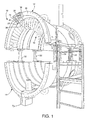
Fig. 1 is a simplified perspective view of upper and lower turbine casing sections, where the upper casing section is raised above the lower casing section for implementing a drilling process in accordance with an exemplary but nonlimiting embodiment described herein; -
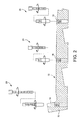
Fig. 2 is a partial section view of the upper casing section showing a plurality of holes drilled in the upper casing section for receiving a corresponding number of sensor elements; -
Fig. 3 is a partial perspective view of the upper casing section, showing vacuum piping installed within the upper casing section; -
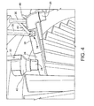
Fig. 4 is another perspective view showing the vacuum piping from a different angle; and -
Figs. 5 is still another partial perspective view showing the vacuum piping installed within the upper casing section. - With reference initially to
Fig. 1 , acompressor case 10 is shown to include an upper casing half section (or, simply, "upper casing section") 12 and a lower casing half section (or, simply, "lower casing section") 14. In theupper casing section 12, a row ofstator blades 16 is visible, it being understood that several rows of stator blades, as well as the remaining blades of the rows of stator blades, are assembled within the upper casing section and that the rotor and its associated rows of blades are assembled within the lower casing section. - In the example embodiment, and with reference to
Fig. 2 , it may be required to drillplural holes 18 into theupper casing section 12 for installation of various ancillary components/features such as, for example, enginehealth monitoring sensors 20 or other instrumentation on a temporary or permanent basis.Fig. 2 shows one possible drilling pattern whereholes 18 are to be drilled at three different axial locations, with, for example, two holes (only one shown) spaced circumferentially at each of the three axial locations. Theholes 18 may vary in diameter from, for example, about ½ inch to an inch or more, depending on the components or sensors to be installed. In addition, the holes normally will be at least partially threaded as shown inFig. 2 . - In order to drill the
holes 18 in theupper casing section 12 in accordance with the exemplary but nonlimiting embodiment, theupper casing section 12 is raised initially from thelower casing section 14 by about 20-30 inches, e.g., 24 inches, as shown inFig. 1 , and supported in the raised position by jacks orother supports 22. This permits sufficient access to the interior of the upper casing section to allow the temporary installation of vacuum apparatus for removing chips/shavings generated during drilling. -
Figs. 3-5 show in greater detail how piping may be inserted temporarily into theupper casing section 12 to facilitate removal of any drill chips/shavings from each hole location. Specifically, for eachhole 18 to be drilled, a piping elbow orvacuum head 24 is fixed to an axially-extendingvacuum tube 26 that terminates at a vacuum supply fitting orconnector 28 where the vacuum is applied (either directly or via additional piping). Tubes 26 may vary in length to accommodate the different axial locations of theholes 18. The elbow orvacuum head 24 andtubes 26 may be of any suitable material such as metal, PVC or the like, andtubes 26 may have a diameter of, for example, 1 to 3 inches, but all dimensions are subject to change depending on specific applications. - The
vacuum head 24 is located directly under and/or engaged with the sensor installation hole location on the casing section. At the opposite end of the piping where a vacuum supply fitting 28 is located, the piping is fixed to arespective support bar 30 that, in turn, is fixed to the uppercasing end face 32 or a temporarily-installedattachment plate 34 that is in turn mounted on thecasing end face 32. Aflexible friction sleeve 36 fitted about thesupply pipe 24 and pulls the piping tightly against conventionalfriction lock device 38 viahandle 40. - In the event one of the
holes 18 to be drilled lies adjacent a flanged edge or other obstruction in the casing such that it is not possible to have the vacuum head engaged with the casing section interior wall at the hole location, it is within the scope of the invention to utilize a funnel-shaped vacuum head as shown at 42 inFigs. 3-5 that may be spaced below the casing wall but is nevertheless effective to catch all metal chips and/or shavings created by the drilling process. The diameter of the funnel-shaped head 42 may vary as needed, and, preferably, the funnel-shaped head is aligned substantially with a center line of the hole to be drilled. It is, of course, contemplated that the funnel-shaped head 42 engage the casing surface where practical. - It will be appreciated that the piping hardware is not limited to the specific arrangement described above. For example,
tubes 26 may be connected to one or more vacuum sources separately, or all of thetubes 26 may be joined to a single manifold (not shown) that is, in turn, connected to a single vacuum source. The number and location of the holes to be drilled will dictate the location and support points for the piping hardware. It will also be appreciated that the vacuum pressure applied may also vary as required to provide effective chip/shaving removal. - Upon completion of the drilling operation and removal of the sensor package components, the vacuum tubes/
heads support rods 30, plate 34) are removed, and theupper casing 12 lowered onto thelower casing 14 and re-secured in the usual manner. Whether the sensor package or other component is installed before or after the re-assembly of the upper and lower casing sections depends on specific applications. - While the invention has been described in connection with what is presently considered to be the most practical and preferred embodiment, it is to be understood that the invention is not to be limited to the disclosed embodiment, but on the contrary, is intended to cover various modifications and equivalent arrangements included within the spirit and scope of the appended claims.
Claims (15)
- A method of drilling one or more holes, substantially in situ, in a turbomachine casing (10), comprising:(a) locating piping (26) including at least one vacuum head (24) within the turbomachine casing in proximity to a hole (18) to be drilled;(b) drilling at least one hole (18) in the casing (10) such that drill chips or shavings caused by the drilling are collected in the vacuum head (24); and(c) applying a vacuum through said piping (26) to said at least one vacuum head (24) to thereby remove the drill chips or shavings collected in said vacuum head (24) to a location outside the turbomachine casing.
- The method of claim 1, wherein during step (a), said vacuum head (24) is engaged with an interior surface of said turbomachine casing (10) substantially directly under said at least one hole (18) to be drilled.
- The method of claim 1 or 2, wherein during step (a), said vacuum head (24) is located below an interior surface of said turbomachine casing (10), in substantially direct alignment with a center line of said at least one hole (18) to be drilled.
- The method of claim 3, wherein said vacuum head comprises a funnel-shaped component (42).
- The method of any of claims 1 to 4, wherein said vacuum head (24) is connected to an axially-oriented section of said piping (26) that extends at least to an edge of said turbomachine casing, said axially-oriented section supported at said edge of said turbomachine casing.
- The method of any preceding claim, wherein said at least one hole (18) comprises multiple holes, and wherein said at least one vacuum head (24) comprises multiple vacuum heads located, respectively, in proximity to each of said multiple holes to be drilled.
- The method of claim 6 wherein a vacuum is applied separately to each vacuum head (24).
- The method of any preceding claim, wherein the turbomachine casing (10) has separable upper and lower casing sections (12,14) the method further comprising:raising the upper casing section (12) a predetermined distance above the lower casing section (14); andlocating the piping (26) into the upper casing section (12).
- The method of claim 8, including securing said piping (26) to an edge (32) of said upper casing section (12) at a location remote from said vacuum head (24).
- The method of claim 9, wherein securing said piping (26) to said upper casing section (12) is achieved at least partially by using a sleeve clamp (36).
- The method of any of claims 8 to 10, wherein, during the upper casing section (12) is raised between about 20-30 inches above the lower casing.
- The method of any of claims 8 to 11, further comprising:(e) removing the piping (26) and vacuum head (24) at each of said the one or more holes; and(f) lowering the upper casing section (12) onto the lower casing section (14).
- Apparatus for removing drilling chips or shavings from inside a turbomachine casing (10) comprising:piping (26) adapted for insertion into the turbomachine casing (10), the piping (26) having a vacuum head (24) at one end and a connector (28) adapted for connection to a vacuum source at an opposite end; and support hardware (30,36) including a clamp (36) for attaching the piping to the turbomachine casing such that the vaccum head is located below a hole to be drilled.
- The apparatus of claim 13, wherein said vacuum head (24) is funnel-shaped.
- The apparatus of claim 13 or 14, wherein said piping (26) includes plural, substantially straight pipe sections, each having a vacuum head (24) at one end.
Applications Claiming Priority (1)
| Application Number | Priority Date | Filing Date | Title |
|---|---|---|---|
| US13/095,498 US8636449B2 (en) | 2011-04-27 | 2011-04-27 | Inner casing vacuum system for a gas turbine engine casing |
Publications (2)
| Publication Number | Publication Date |
|---|---|
| EP2518281A2 true EP2518281A2 (en) | 2012-10-31 |
| EP2518281A3 EP2518281A3 (en) | 2017-08-23 |
Family
ID=46000983
Family Applications (1)
| Application Number | Title | Priority Date | Filing Date |
|---|---|---|---|
| EP12165066.7A Withdrawn EP2518281A3 (en) | 2011-04-27 | 2012-04-20 | Inner casing vacuum system for a gas turbine engine casing |
Country Status (3)
| Country | Link |
|---|---|
| US (1) | US8636449B2 (en) |
| EP (1) | EP2518281A3 (en) |
| CN (1) | CN102777219B (en) |
Cited By (1)
| Publication number | Priority date | Publication date | Assignee | Title |
|---|---|---|---|---|
| EP3061566A1 (en) * | 2015-02-04 | 2016-08-31 | United Technologies Corporation | Process of boas grinding in situ |
Families Citing this family (5)
| Publication number | Priority date | Publication date | Assignee | Title |
|---|---|---|---|---|
| US8984730B2 (en) * | 2012-02-07 | 2015-03-24 | General Electric Company | System and method for rotating a turbine shell |
| CN104439366B (en) * | 2014-11-18 | 2016-12-07 | 哈尔滨汽轮机厂有限责任公司 | A kind of turbine high-pressure outer shell back oblique flange hole Boring machine processing method |
| PL411550A1 (en) * | 2015-03-13 | 2016-09-26 | General Electric Company | The layout and method of lifting the exhaust frame of a turbine machine |
| US9803647B2 (en) | 2015-07-21 | 2017-10-31 | General Electric Company | Method and system for repairing turbomachine dovetail slots |
| US10988268B2 (en) * | 2018-06-14 | 2021-04-27 | General Electric Company | System and method for performing operations on an engine |
Family Cites Families (16)
| Publication number | Priority date | Publication date | Assignee | Title |
|---|---|---|---|---|
| US4738571A (en) * | 1982-09-29 | 1988-04-19 | Olson Eugene T | Routing apparatus with dust extraction system |
| GB2240735A (en) * | 1990-02-13 | 1991-08-14 | Rolls Royce Plc | Portable machine tool |
| US5034041A (en) * | 1990-06-26 | 1991-07-23 | Tennessee Valley Authority | Tent-free apparatus for particulate contamination control |
| JP3774819B2 (en) * | 1996-04-02 | 2006-05-17 | 株式会社レンタルのニッケン | Dust collector on construction site |
| US6200075B1 (en) * | 2000-05-16 | 2001-03-13 | The Boeing Company | Drill motor vacuum attachment |
| DE10053128C1 (en) * | 2000-10-26 | 2002-08-08 | Bruno Gruber | Bohrstaubabsaugvorrichtung |
| DE10106672B4 (en) * | 2001-02-14 | 2004-03-18 | Koenig & Bauer Ag | Slitter |
| DE10258301A1 (en) * | 2002-12-13 | 2004-07-15 | Alexey Layer | Vacuum cleaner hose adapter has ceiling suction pad with extension tube and universal joint to nozzle close to falling drilling debris |
| GB0315944D0 (en) * | 2003-07-08 | 2003-08-13 | British Nuclear Fuels Plc | Dry drilling |
| US7160063B2 (en) * | 2003-10-24 | 2007-01-09 | The Boeing Company | Coolant feed drill nozzle with thrust-vectored exhaust |
| DE102004006894A1 (en) | 2004-02-12 | 2005-09-01 | Ex-Cell-O Gmbh | Machine tool, transfer machine tool and method for machining a workpiece |
| US20090181606A1 (en) * | 2008-01-15 | 2009-07-16 | Michael Loveless | Vacuum shroud for use with drilling tools |
| US8677591B2 (en) * | 2008-04-28 | 2014-03-25 | General Electric Company | Methods and system for disassembling a machine |
| US8534965B2 (en) * | 2009-04-17 | 2013-09-17 | General Electric Company | Apparatus and tools for use with compressors |
| US8602390B2 (en) * | 2010-11-30 | 2013-12-10 | General Electric Company | Jacking mechanism |
| US9108829B2 (en) * | 2010-12-09 | 2015-08-18 | General Electric Company | Casing section lift and transport system |
-
2011
- 2011-04-27 US US13/095,498 patent/US8636449B2/en not_active Expired - Fee Related
-
2012
- 2012-04-20 EP EP12165066.7A patent/EP2518281A3/en not_active Withdrawn
- 2012-04-27 CN CN201210143345.3A patent/CN102777219B/en not_active Expired - Fee Related
Non-Patent Citations (1)
| Title |
|---|
| None |
Cited By (2)
| Publication number | Priority date | Publication date | Assignee | Title |
|---|---|---|---|---|
| EP3061566A1 (en) * | 2015-02-04 | 2016-08-31 | United Technologies Corporation | Process of boas grinding in situ |
| US9719364B2 (en) | 2015-02-04 | 2017-08-01 | United Technologies Corporation | Process of boas grinding in situ |
Also Published As
| Publication number | Publication date |
|---|---|
| CN102777219B (en) | 2016-09-07 |
| US8636449B2 (en) | 2014-01-28 |
| CN102777219A (en) | 2012-11-14 |
| US20120275873A1 (en) | 2012-11-01 |
| EP2518281A3 (en) | 2017-08-23 |
Similar Documents
| Publication | Publication Date | Title |
|---|---|---|
| US8636449B2 (en) | Inner casing vacuum system for a gas turbine engine casing | |
| WO2009054050A1 (en) | Method for demounting blade ring and member for demounting blade ring | |
| EP2500653B1 (en) | Tool for changing a combustor liner and a flow sleeve | |
| ES2757597T3 (en) | Disassembly procedure for gas turbines and calibration device | |
| EP3217170A1 (en) | Engine health monitoring using acoustic sensors | |
| CN102794739B (en) | For removing the instrument of pin from gas turbine housing | |
| CN107109908B (en) | Motor shaft transmission interference device | |
| US9914178B2 (en) | Drilling tool and method for modifying a blind hole | |
| JP2008286195A (en) | Support bar with adjustable shim design for turbine diaphragm | |
| US20160332267A1 (en) | Turbomachine component displacement apparatus and method of use | |
| US8910374B2 (en) | Service apparatus for turbomachine | |
| AU2011218349B2 (en) | Articulated pre-skimmer mount | |
| JP5729909B2 (en) | Apparatus and method for extracting / incorporating internal member of pump | |
| CN119103441A (en) | A method for detecting karst underground river system | |
| CN115326336B (en) | Impact resistance measuring device for tunnels and its usage method | |
| US20170358908A1 (en) | System and method for electrical infrastructure maintenance | |
| JP6074258B2 (en) | Drawing method for double-ended spindle | |
| KR20190001638A (en) | Lower base assembly for Steel Pole | |
| US20200087989A1 (en) | Hydro boring systems and methods | |
| RU2713230C2 (en) | Method for creating and repairing turbomachine component and associated turbomachine component | |
| JP7369832B1 (en) | Piping fixing fittings | |
| JP2015034546A (en) | Remote turbine component replacement apparatus and method of remotely replacing turbine component | |
| JP6910743B2 (en) | Horizontal axis pump | |
| JP2004190345A (en) | Fixing bracket for earthquake resistant measure | |
| JP2789125B2 (en) | Method and apparatus for mounting detection wire for position management of excavator |
Legal Events
| Date | Code | Title | Description |
|---|---|---|---|
| PUAI | Public reference made under article 153(3) epc to a published international application that has entered the european phase |
Free format text: ORIGINAL CODE: 0009012 |
|
| AK | Designated contracting states |
Kind code of ref document: A2 Designated state(s): AL AT BE BG CH CY CZ DE DK EE ES FI FR GB GR HR HU IE IS IT LI LT LU LV MC MK MT NL NO PL PT RO RS SE SI SK SM TR |
|
| AX | Request for extension of the european patent |
Extension state: BA ME |
|
| PUAL | Search report despatched |
Free format text: ORIGINAL CODE: 0009013 |
|
| AK | Designated contracting states |
Kind code of ref document: A3 Designated state(s): AL AT BE BG CH CY CZ DE DK EE ES FI FR GB GR HR HU IE IS IT LI LT LU LV MC MK MT NL NO PL PT RO RS SE SI SK SM TR |
|
| AX | Request for extension of the european patent |
Extension state: BA ME |
|
| RIC1 | Information provided on ipc code assigned before grant |
Ipc: B23Q 11/00 20060101ALI20170717BHEP Ipc: B23B 41/00 20060101ALI20170717BHEP Ipc: F01D 25/24 20060101AFI20170717BHEP Ipc: B23B 35/00 20060101ALI20170717BHEP |
|
| 17P | Request for examination filed |
Effective date: 20180223 |
|
| RBV | Designated contracting states (corrected) |
Designated state(s): AL AT BE BG CH CY CZ DE DK EE ES FI FR GB GR HR HU IE IS IT LI LT LU LV MC MK MT NL NO PL PT RO RS SE SI SK SM TR |
|
| STAA | Information on the status of an ep patent application or granted ep patent |
Free format text: STATUS: THE APPLICATION IS DEEMED TO BE WITHDRAWN |
|
| 18D | Application deemed to be withdrawn |
Effective date: 20191101 |