EP2517941A1 - Roll angle estimation device and transport equipment - Google Patents
Roll angle estimation device and transport equipment Download PDFInfo
- Publication number
- EP2517941A1 EP2517941A1 EP10838866A EP10838866A EP2517941A1 EP 2517941 A1 EP2517941 A1 EP 2517941A1 EP 10838866 A EP10838866 A EP 10838866A EP 10838866 A EP10838866 A EP 10838866A EP 2517941 A1 EP2517941 A1 EP 2517941A1
- Authority
- EP
- European Patent Office
- Prior art keywords
- roll angle
- angular velocity
- acceleration
- speed
- movable object
- Prior art date
- Legal status (The legal status is an assumption and is not a legal conclusion. Google has not performed a legal analysis and makes no representation as to the accuracy of the status listed.)
- Granted
Links
Images







Classifications
-
- B—PERFORMING OPERATIONS; TRANSPORTING
- B60—VEHICLES IN GENERAL
- B60W—CONJOINT CONTROL OF VEHICLE SUB-UNITS OF DIFFERENT TYPE OR DIFFERENT FUNCTION; CONTROL SYSTEMS SPECIALLY ADAPTED FOR HYBRID VEHICLES; ROAD VEHICLE DRIVE CONTROL SYSTEMS FOR PURPOSES NOT RELATED TO THE CONTROL OF A PARTICULAR SUB-UNIT
- B60W40/00—Estimation or calculation of non-directly measurable driving parameters for road vehicle drive control systems not related to the control of a particular sub unit, e.g. by using mathematical models
- B60W40/10—Estimation or calculation of non-directly measurable driving parameters for road vehicle drive control systems not related to the control of a particular sub unit, e.g. by using mathematical models related to vehicle motion
- B60W40/112—Roll movement
-
- B—PERFORMING OPERATIONS; TRANSPORTING
- B62—LAND VEHICLES FOR TRAVELLING OTHERWISE THAN ON RAILS
- B62J—CYCLE SADDLES OR SEATS; AUXILIARY DEVICES OR ACCESSORIES SPECIALLY ADAPTED TO CYCLES AND NOT OTHERWISE PROVIDED FOR, e.g. ARTICLE CARRIERS OR CYCLE PROTECTORS
- B62J45/00—Electrical equipment arrangements specially adapted for use as accessories on cycles, not otherwise provided for
- B62J45/40—Sensor arrangements; Mounting thereof
- B62J45/41—Sensor arrangements; Mounting thereof characterised by the type of sensor
- B62J45/415—Inclination sensors
- B62J45/4151—Inclination sensors for sensing lateral inclination of the cycle
-
- B—PERFORMING OPERATIONS; TRANSPORTING
- B60—VEHICLES IN GENERAL
- B60W—CONJOINT CONTROL OF VEHICLE SUB-UNITS OF DIFFERENT TYPE OR DIFFERENT FUNCTION; CONTROL SYSTEMS SPECIALLY ADAPTED FOR HYBRID VEHICLES; ROAD VEHICLE DRIVE CONTROL SYSTEMS FOR PURPOSES NOT RELATED TO THE CONTROL OF A PARTICULAR SUB-UNIT
- B60W50/00—Details of control systems for road vehicle drive control not related to the control of a particular sub-unit, e.g. process diagnostic or vehicle driver interfaces
- B60W2050/0001—Details of the control system
- B60W2050/0043—Signal treatments, identification of variables or parameters, parameter estimation or state estimation
- B60W2050/0052—Filtering, filters
- B60W2050/0054—Cut-off filters, retarders, delaying means, dead zones, threshold values or cut-off frequency
- B60W2050/0056—Low-pass filters
-
- B—PERFORMING OPERATIONS; TRANSPORTING
- B60—VEHICLES IN GENERAL
- B60W—CONJOINT CONTROL OF VEHICLE SUB-UNITS OF DIFFERENT TYPE OR DIFFERENT FUNCTION; CONTROL SYSTEMS SPECIALLY ADAPTED FOR HYBRID VEHICLES; ROAD VEHICLE DRIVE CONTROL SYSTEMS FOR PURPOSES NOT RELATED TO THE CONTROL OF A PARTICULAR SUB-UNIT
- B60W2300/00—Indexing codes relating to the type of vehicle
- B60W2300/36—Cycles; Motorcycles; Scooters
-
- B—PERFORMING OPERATIONS; TRANSPORTING
- B60—VEHICLES IN GENERAL
- B60W—CONJOINT CONTROL OF VEHICLE SUB-UNITS OF DIFFERENT TYPE OR DIFFERENT FUNCTION; CONTROL SYSTEMS SPECIALLY ADAPTED FOR HYBRID VEHICLES; ROAD VEHICLE DRIVE CONTROL SYSTEMS FOR PURPOSES NOT RELATED TO THE CONTROL OF A PARTICULAR SUB-UNIT
- B60W2520/00—Input parameters relating to overall vehicle dynamics
-
- B—PERFORMING OPERATIONS; TRANSPORTING
- B60—VEHICLES IN GENERAL
- B60W—CONJOINT CONTROL OF VEHICLE SUB-UNITS OF DIFFERENT TYPE OR DIFFERENT FUNCTION; CONTROL SYSTEMS SPECIALLY ADAPTED FOR HYBRID VEHICLES; ROAD VEHICLE DRIVE CONTROL SYSTEMS FOR PURPOSES NOT RELATED TO THE CONTROL OF A PARTICULAR SUB-UNIT
- B60W2520/00—Input parameters relating to overall vehicle dynamics
- B60W2520/10—Longitudinal speed
-
- B—PERFORMING OPERATIONS; TRANSPORTING
- B60—VEHICLES IN GENERAL
- B60W—CONJOINT CONTROL OF VEHICLE SUB-UNITS OF DIFFERENT TYPE OR DIFFERENT FUNCTION; CONTROL SYSTEMS SPECIALLY ADAPTED FOR HYBRID VEHICLES; ROAD VEHICLE DRIVE CONTROL SYSTEMS FOR PURPOSES NOT RELATED TO THE CONTROL OF A PARTICULAR SUB-UNIT
- B60W2520/00—Input parameters relating to overall vehicle dynamics
- B60W2520/10—Longitudinal speed
- B60W2520/105—Longitudinal acceleration
-
- B—PERFORMING OPERATIONS; TRANSPORTING
- B60—VEHICLES IN GENERAL
- B60W—CONJOINT CONTROL OF VEHICLE SUB-UNITS OF DIFFERENT TYPE OR DIFFERENT FUNCTION; CONTROL SYSTEMS SPECIALLY ADAPTED FOR HYBRID VEHICLES; ROAD VEHICLE DRIVE CONTROL SYSTEMS FOR PURPOSES NOT RELATED TO THE CONTROL OF A PARTICULAR SUB-UNIT
- B60W2520/00—Input parameters relating to overall vehicle dynamics
- B60W2520/12—Lateral speed
- B60W2520/125—Lateral acceleration
-
- B—PERFORMING OPERATIONS; TRANSPORTING
- B60—VEHICLES IN GENERAL
- B60W—CONJOINT CONTROL OF VEHICLE SUB-UNITS OF DIFFERENT TYPE OR DIFFERENT FUNCTION; CONTROL SYSTEMS SPECIALLY ADAPTED FOR HYBRID VEHICLES; ROAD VEHICLE DRIVE CONTROL SYSTEMS FOR PURPOSES NOT RELATED TO THE CONTROL OF A PARTICULAR SUB-UNIT
- B60W2520/00—Input parameters relating to overall vehicle dynamics
- B60W2520/14—Yaw
-
- B—PERFORMING OPERATIONS; TRANSPORTING
- B60—VEHICLES IN GENERAL
- B60W—CONJOINT CONTROL OF VEHICLE SUB-UNITS OF DIFFERENT TYPE OR DIFFERENT FUNCTION; CONTROL SYSTEMS SPECIALLY ADAPTED FOR HYBRID VEHICLES; ROAD VEHICLE DRIVE CONTROL SYSTEMS FOR PURPOSES NOT RELATED TO THE CONTROL OF A PARTICULAR SUB-UNIT
- B60W2520/00—Input parameters relating to overall vehicle dynamics
- B60W2520/16—Pitch
-
- B—PERFORMING OPERATIONS; TRANSPORTING
- B60—VEHICLES IN GENERAL
- B60W—CONJOINT CONTROL OF VEHICLE SUB-UNITS OF DIFFERENT TYPE OR DIFFERENT FUNCTION; CONTROL SYSTEMS SPECIALLY ADAPTED FOR HYBRID VEHICLES; ROAD VEHICLE DRIVE CONTROL SYSTEMS FOR PURPOSES NOT RELATED TO THE CONTROL OF A PARTICULAR SUB-UNIT
- B60W2520/00—Input parameters relating to overall vehicle dynamics
- B60W2520/18—Roll
-
- B—PERFORMING OPERATIONS; TRANSPORTING
- B60—VEHICLES IN GENERAL
- B60Y—INDEXING SCHEME RELATING TO ASPECTS CROSS-CUTTING VEHICLE TECHNOLOGY
- B60Y2200/00—Type of vehicle
- B60Y2200/10—Road Vehicles
- B60Y2200/12—Motorcycles, Trikes; Quads; Scooters
Definitions
- the present invention relates to a roll angle estimation device and transport equipment including the same.
- the aim of a headlight can be controlled on the basis of the roll angle estimated by an estimation device, so that the headlight can emit light in an appropriate direction irrespective of the inclination of the vehicle.
- a vehicle posture estimation device described in Patent Document 1 estimates a roll angle and a pitch angle on the basis of detected values of longitudinal acceleration, lateral acceleration, vertical acceleration, yaw acceleration, and roll angular velocity of the vehicle motion, and also on the basis of an estimated value of longitudinal vehicle body speed and an estimated value of pitch angular velocity.
- Patent Document 1 JP 2009-73466 A
- the conventional estimation device cannot estimate the roll angle of a vehicle with high accuracy. This may cause, for example, the headlight aim to be askew even though the vehicle is not inclined.
- An object of the present invention is to provide a roll angle estimation device that can estimate the roll angle of a movable object with high accuracy, and transport equipment including the same.
- the first and second angular velocities about the first and second axes extending in at least two directions are detected by the first and second angular velocity detectors, respectively Further, the first, second, and third accelerations in at least three directions are detected by the first, second, and third acceleration detectors, respectively Furthermore, the information regarding the moving speed in the traveling direction of the movable object is detected by the speed information detector. Then, the roll angle of the movable object is estimated by the estimator, and an offset error of the detected value of at least one detector among the first and second angular velocity detectors and the first, second, and third acceleration detectors is estimated by the estimator.
- the estimator estimates the roll angle of the movable object and the at least one offset error in a current estimation operation on the basis of the detected values of the first and second angular velocity detectors, the detected values of the first, second, and third acceleration detectors, the detected value of the speed information detector, the estimated value of the roll angle obtained in the previous estimation operation, and the estimated value of the offset error obtained in the previous estimation operation.
- the offset error is estimated as well as the roll angle, and the estimated value of the offset error is used in a next estimation operation. This compensates the degradation in estimation accuracy of the roll angle due to the offset error of at least one of the first and second angular velocity detectors and the first, second, and third acceleration detectors. As a result, the roll angle can be estimated with high accuracy
- the first and second angular velocity detectors may respectively detect the first and second angular velocities about the first and second axes extending in directions different from each other, and the first, second, and third acceleration detectors may respectively detect the first, second, and third accelerations in first, second, and third directions different from one another.
- the first and second angular velocities about the first and second axes extending in different directions are detected by the first and second angular velocity detectors, respectively.
- the first, second, and third accelerations in the first, second, and third directions different from one another are detected by the first, second, and third acceleration detectors, respectively.
- the estimator may estimate an offset error of at least one of the first and second angular velocity detectors as the at least one offset error.
- An angular velocity detector is susceptible to an offset error compared to an acceleration detector. Therefore, the use of the estimated value of the offset error of at least one of the first and second angular velocity detectors in the next estimation operation leads to a sufficiently improved estimation accuracy of the roll angle.
- the estimator may estimate offset errors of the first and second angular velocity detectors as the at least one offset error.
- the estimator may further estimate an offset error of at least one of the first, second, and third acceleration detectors as the at least one offset error.
- the use of the estimated value of the offset error of at least one of the first, second, and third acceleration detectors, in addition to the estimated value of the offset error of at least one of the first and second angular velocity detectors, in the next estimation operation leads to a further improvement of the estimation accuracy of the roll angle.
- the first acceleration may be an acceleration in an up-and-down direction of the movable object, and the estimator may estimate the offset error of the first acceleration detector.
- the acceleration in the up-and-down direction of the movable object hardly changes. If the detected value of such an acceleration in the up-and-down direction changes due to the offset error of the first acceleration detector the change in the detected value of the acceleration in the up-and-down direction will largely affect the estimation of the roll angle. Therefore, the use of the estimated value of the offset error of the first acceleration detector in the next estimation operation leads to a further improvement of the estimation accuracy of the roll angle in the range where the roll angle is small.
- the movable object may have a front wheel and a rear wheel, and the speed information detector may include a rear-wheel rotational speed detector that detects a rotational speed of the rear wheel as the information.
- the estimator may be configured to further estimate a moving speed of the movable object, and may estimate the roll angle of the movable object, the at least one offset error, and the moving speed of the movable object in the current estimation operation on the basis of the detected values of the first and second angular velocity detectors, the detected values of the first, second, and third acceleration detectors, a detected value of the rear-wheel speed detector, the estimated value of the roll angle obtained in the previous estimation operation, the estimated value of the offset error obtained in the previous estimation operation, and an estimated value of the moving speed obtained in the previous estimation operation.
- the roll angle of the movable object, the at least one offset error, and the moving speed of the movable object can be estimated in the current estimation operation on the basis of the detected values of the first and second angular velocity detectors, the detected values of the first, second, and third acceleration detectors, the detected value of the rotational speed of the rear wheel, the estimated value of the roll angle obtained in the previous estimation operation, the estimated value of the offset error obtained in the previous estimation operation, and the estimated value of the moving speed obtained in the previous estimation operation.
- the rotational speed of the rear wheel is closer to the moving speed of the movable object compared to the rotational speed of the front wheel. Therefore, the use of the detected value of the rotational speed of the rear wheel makes it possible to estimate the roll angle of the movable object, the at least one offset error, and the moving speed of the movable object with high accuracy.
- the movable object may have a front wheel and a rear wheel
- the speed information detector may include a front-wheel rotational speed detector that detects a rotational speed of the front wheel, and a rear-wheel rotational speed estimator that estimates, as the information, a rotational speed of the rear wheel from a detected value of the front-wheel rotational speed detector.
- the estimator may be configured to further estimate a moving speed of the movable object, and may estimate the roll angle of the movable object, the at least one offset error, and the moving speed of the movable object in the current estimation operation on the basis of the detected values of the first and second angular velocity detectors, the detected values of the first, second, and third acceleration detectors, an estimated value of the rear-wheel speed detector, the estimated value of the roll angle obtained in the previous estimation operation, the estimated value of the offset error obtained in the previous estimation operation, and an estimated value of the moving speed obtained in the previous estimation operation.
- the rotational speed of the front wheel detected by the front-wheel rotational speed detector is higher than the rotational speed of the rear wheel.
- the rotational speed of the rear wheel is estimated by the rear-wheel rotational speed estimator from the detected value of the front-wheel rotational speed detector. This allows the roll angle of the movable object, the at least one offset error, and the moving speed of the movable object to be estimated with high accuracy in the case where the front-wheel rotational speed detector is provided, as in the case where the rear-wheel rotational speed detector is provided.
- the estimator may include a Kalman filter that estimates the roll angle of the movable object and the at least one offset error in the current estimation operation by using a relationship among the detected values of the first and second angular velocity detectors, the detected values of the first, second, and third acceleration detectors, the detected value of the speed information detector, the estimated value of the roll angle obtained in the previous estimation operation, and the estimated value of the offset error obtained in the previous estimation operation.
- the estimator can readily be implemented by using the algorithm of the Kalman filter.
- transport equipment includes a movable object configured to be moveable, the roll angle estimation device, according to the above invention, that estimates a roll angle of the movable object, and a processor that performs processing using the roll angle estimated by the roll angle estimation device.
- the roll angle of the movable portion is estimated with high accuracy by the roll angle estimation device according to the above invention. This ensures that the processing by the processor using the roll angle is performed with high accuracy.
- FIG. 1 is a schematic view of the vehicle including the roll angle estimation device according to an embodiment of the present invention.
- the vehicle 100 in FIG. 1 is a motorcycle.
- the vehicle 100 includes a vehicle body 1.
- the vehicle body 1 has a front wheel 2 attached to the front thereof and a rear wheel 3 attached to the rear thereof.
- the vehicle body 1 also has a sensor group 5 attached to the center thereof. The sensor group 5 will be described later in detail.
- a rear-wheel speed sensor 7 for detecting the rotational speed of the rear wheel 3 is attached to the wheel of the rear wheel 3.
- a handlebar 11 is provided so as to be swingable right and left.
- a navigation system 12 is provided near the handlebar 11.
- the vehicle body 1 further has a headlight 14 and a headlight driving device 15 provided at the front thereof.
- the headlight driving device 15 controls the aim of the headlight 14.
- the vehicle body 1 has an electronic control unit (hereinafter, abbreviated as ECU) 20 provided at the rear thereof.
- ECU electronice control unit
- Signals output from the sensor group 5 and the rear-wheel speed sensor 7 are fed to the ECU 20.
- the ECU 20 controls the components of the vehicle body 1.
- the ECU 20 also estimates the roll angle of the vehicle body 1, and feeds the estimated roll angle to, for example, the navigation system 12 and the headlight driving device 15.
- the sensor group 5, the rear-wheel speed sensor 9, and the ECU 20 constitute the roll angle estimation device.
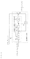
- FIG. 2 is a block diagram showing the configuration of the roll angle estimation device according to an embodiment of the present invention.
- the roll angle estimation device 10 in FIG. 2 is made up of the sensor group 5, the rear-wheel speed sensor 7, low pass filters 61-65, differentiators 71, 72, and a Kalman filter 80.
- the functions of the Kalman filter 80 are implemented by the ECU 20 in FIG. 1 and a program.
- the sensor group 5 includes a roll angular velocity sensor 51, a yaw angular velocity sensor 52, a vertical acceleration sensor 53, a longitudinal acceleration sensor 54, and a lateral acceleration sensor 55.
- the roll angular velocity sensor 51 is disposed on the vehicle body 1 so as to detect the roll angular velocity of the vehicle body 1.
- the roll angular velocity refers to the angular velocity about a longitudinal axis of the vehicle 100.
- the yaw angular velocity sensor 52 is disposed on the vehicle body 1 so as to detect the yaw angular velocity of the vehicle body 1.
- the yaw angular velocity refers to the angular velocity about a vertical axis of the vehicle 100.
- the vertical acceleration sensor 53 is disposed on the vehicle body 1 so as to detect the vertical acceleration of the vehicle body 1.
- the vertical acceleration refers to the acceleration in an up-and-down direction of the vehicle body 1.
- the longitudinal acceleration sensor 54 is disposed on the vehicle body 1 so as to detect the longitudinal acceleration of the vehicle body 1.
- the longitudinal acceleration refers to the acceleration in a forward-and-backward direction of the vehicle body 1.
- the lateral acceleration sensor 55 is disposed on the vehicle body 1 so as to detect the lateral acceleration of the vehicle body 1.
- the lateral acceleration refers to the acceleration in a right-and-left direction of the vehicle body 1.
- the signal output from the roll angular velocity sensor 51 is fed through the low pass filter 61 to the Kalman filter 80 and the differentiator 71 as a roll angular velocity.
- the low pass filter 61 removes noise from the output signal of the roll angular velocity sensor 51.
- the differentiator 71 feeds a differential value of the roll angular velocity, as a roll angular acceleration, to the Kalman filter 80.
- the signal output from the yaw angular velocity sensor 52 is fed through the low pass filter 62 to the Kalman filter 80 and the differentiator 72 as a yaw angular velocity.
- the low pass filter 62 removes noise from the output signal of the yaw angular velocity sensor 52.
- the differentiator 72 feeds a differential value of the yaw angular velocity, as a yaw angular acceleration, to the Kalman filter 80.
- the signal output from the vertical acceleration sensor 53 is fed through the low pass filter 63 to the Kalman filter 80 as a vertical acceleration.
- the signal output from the longitudinal acceleration sensor 54 is fed through the low pass filter 64 to the Kalman filter 80 as a longitudinal acceleration.
- the signal output from the lateral acceleration sensor 55 is fed through the low pass filter 65 to the Kalman filter 80 as a lateral acceleration.
- the signal output from the rear-wheel speed sensor 7 is fed to the Kalman filter 80 as a rear-wheel speed.
- the rear-wheel speed refers to the rotational speed at the outermost periphery of the tire of the rear wheel 3 on the assumption that there is no slip between the road surface and the tire.
- the rear-wheel speed is practically calculated on the basis of the output signal from the rear-wheel speed sensor 7 and the tire size. For simplification of the explanation, it is assumed in FIG. 2 that the rear-wheel speed sensor 7 outputs a signal that indicates the rear-wheel speed
- the roll angular velocity, roll angular acceleration, yaw angular velocity, yaw angular acceleration, vertical acceleration, longitudinal acceleration, lateral acceleration, and rear-wheel speed are denoted by the symbols shown in the following table. It is noted that a single dot placed at the top of the symbol representing a parameter indicates first order differentiation.
- the Kalman filter 80 estimates and outputs the roll angle, vehicle speed, roll angular velocity sensor offset, yaw angular velocity sensor offset, and vertical acceleration sensor offset.
- the vertical plane parallel to the traveling direction of the vehicle 100 is called the longitudinal vertical plane
- the vertical plane perpendicular to the longitudinal vertical plane is called the lateral vertical plane.
- the roll angle refers to the tilt angle of the vehicle body 1 with respect to the direction of gravity in the lateral vertical plane.
- the vehicle speed refers to the speed in the traveling direction of the vehicle body 1.
- the roll angular velocity sensor offset refers to the offset error of the roll angular velocity sensor 51.
- the yaw angular velocity sensor offset refers to the offset error of the yaw angular velocity sensor 52.
- the vertical acceleration sensor offset refers to the offset error of the vertical acceleration sensor 53.
- the vehicle speed, roll angular velocity sensor offset, yaw angular velocity sensor offset, and vertical acceleration sensor offset are denoted by the symbols shown in the following table.
- the roll angular velocity sensor 51, the yaw angular velocity sensor 52, the vertical acceleration sensor 53, the longitudinal acceleration sensor 54, the lateral acceleration sensor 55, and the rear-wheel speed sensor 7 are used to derive five relational expressions in expressions (17), (18), which will be described later.
- two parameters of roll angle ⁇ and vehicle speed V x are estimated. That is, there exists redundancy between the number of relational expressions and the number of outputs to be estimated. In other words, the number of relational expressions is greater than the number of outputs to be estimated.
- the use of this redundancy makes it possible to estimate the roll angular velocity sensor offset b r , the yaw angular velocity sensor offset by, and the vertical acceleration sensor offset b z .
- FIG. 3 is a diagram showing the concept of the Kalman filter 80.
- the Kalman filter 80 in FIG. 3 uses a kinematic model of the vehicle 100 as described below.
- the Kalman filter 80 is made up of a system equation 8a, an adding function 8b, an integrating function 8c, an observation equation 8d, a subtracting function 8e, and a Kalman gain 8f.
- the system equation 8a includes the function f(x, u).
- the observation equation 8d includes the function h(x).
- the Kalman gain 8f includes a fifth-order Kalman gain K
- a detected value of the roll angular velocity ⁇ r a detected value of the roll angular acceleration (differential value of the roll angular velocity ⁇ r ), a detected value of the yaw angular velocity ⁇ y , the yaw angular acceleration (differential value of the yaw angular velocity ⁇ y ), and a detected value of the longitudinal acceleration G x are given as input parameters u to the system equation 8a.
- the estimated value of the roll angle ⁇ , the estimated value of the vehicle speed V x , the estimated value of the roll angular velocity sensor offset b r , the estimated value of the yaw angular velocity sensor offset by, and the estimated value of the vertical acceleration sensor offset h z obtained in the previous estimation operation are given as input parameters x to the system equation 8a.
- the system equation 8a outputs a differential value of the roll angle ⁇ , a differential value of the vehicle speed V x , a differential value of the roll angular velocity sensor offset b r , a differential value of the yaw angular velocity sensor offset by, and a differential value of the vertical acceleration sensor offset h z .
- a fifth-order Kalman gain K obtained in the previous estimation operation is added.
- the differential value of the roll angle ⁇ , the differential value of the vehicle speed V x , the differential value of the roll angular velocity sensor offset b r , the differential value of the yaw angular velocity sensor offset b y , and the differential value of the vertical acceleration sensor offset b z , with the Kalman gain K added thereto, are integrated, so that an estimated value of the roll angle ⁇ , an estimated value of the vehicle speed V x , an estimated value of the roll angular velocity sensor offset b r , an estimated value of the yaw angular velocity sensor offset by, and an estimated value of the vertical acceleration sensor offset b z according to the current estimation operation are obtained.
- the estimated value of the roll angle ⁇ , the estimated value of the vehicle speed V x , the estimated value of the roll angular velocity sensor offset b r , the estimated value of the yaw angular velocity sensor offset b y , and the estimated value of the vertical acceleration sensor offset b z are given as input parameters x to the observation equation 8d. From the observation equation 8d, a calculated value of the vertical acceleration G z , a calculated value of the lateral acceleration G y , and a calculated value of the rear-wheel speed v r are obtained.
- a detected value of the vertical acceleration G z a detected value of the lateral acceleration G y , and a detected value of the rear-wheel speed v r are given as input parameters y to the Kalman filter 80.
- the Kalman gain K is calculated on the basis of the differences between the detected values and the calculated values of the vertical acceleration G z , the lateral acceleration G y , and the rear-wheel speed v r .
- the roll angle, differential value of the roll angle, pitch angle, differential value of the pitch angle, yaw angle, differential value of the yaw angle, roll angular velocity, yaw angular velocity, and pitch angular velocity are denoted by the symbols shown in the following table.
- FIG. 4 is a diagram illustrating the attachment position of the sensor group 5.
- the left side of the vehicle 100 is shown on the left, and the front of the vehicle 100 is shown on the right.
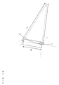
- FIG. 5 is a cross-sectional view of the rear wheel 3.
- FIG. 6 is a diagram showing the attachment position of the sensor group 5 in vectors.
- the attachment position of the sensor group 5 is denoted PS.
- the horizontal distance from the attachment position PS to the center of the rear wheel 3 is denoted L, and the height from the road surface to the attachment position PS is denoted h.
- the rear wheel 3 is tilted by a roll angle ⁇ with respect to the road surface RD.
- the road surface RD has no slope, from the above assumption (d).
- the contact point between the tire TR of the rear wheel 3 and the road surface RD is denoted P.
- the radius of the cross section of the tire TR of the rear wheel 3 is denoted R cr
- the radius of the rear wheel 3 is denoted R e .
- the position vector of the attachment position PS of the sensor group 5 with respect to the origin O of the inertial coordinate system is denoted rv
- the position vector of the ground contact point P with respect to the origin O of the inertial coordinate system is denoted rv 0
- the vector from the ground contact point P to the attachment position PS of the sensor group 5 is denoted ⁇ v.
- rv rv 0 + ⁇ v.
- the second-order differential vector of the position vector rv is denoted by the symbols shown in the following table. It is noted that two dots placed at the top of the symbol representing a parameter indicate second order differentiation.
- the acceleration vector detected by the vertical acceleration sensor 53, the longitudinal acceleration sensor 54, and the lateral acceleration sensor 55 at the attachment position PS is denoted Gv.
- the acceleration vector Gv is obtained by adding the gravitational acceleration vector to the second-order differential vector of the position vector rv, as in the following expression:
- ⁇ represents a matrix. From FIGS. 4 and 5 , the matrix ⁇ in the above expression (5) is represented by the following expression:
- a x , a y , and a z are functions.
- the functions a x , a y , a z can be found by calculating the above expressions (5) and (6).
- the above expression (3) can be used to eliminate the differential value of the roll angle ⁇ and the differential value of the yaw angle ⁇ .
- the sideslip speed of the vehicle 100 is denoted V y .
- V x the vehicle speed
- V y the sideslip speed of the vehicle 100
- [e0] [e0 1 , e0 2 , e0 3 ].
- g represents the magnitude of the gravitational acceleration.
- the acceleration vector Gv detected at the attachment position PS is represented by the following expression:
- the acceleration vector Gv detected at the attachment position PS is represented by the following expression:
- G y G z ⁇ r V x ⁇ ⁇ y + a x ⁇ r ⁇ ⁇ y . ⁇ ⁇ r . ⁇ ⁇ y . ⁇ . L . h . R cr + gsin ⁇ ⁇ - V x ⁇ ⁇ y ⁇ tan ⁇ + a z ⁇ r ⁇ ⁇ y . ⁇ ⁇ r . ⁇ ⁇ y . ⁇ . L . h . R cr + gcos ⁇ ⁇ - 1 1 - R cr / R ⁇ ⁇ 1 - cos ⁇ ⁇ V
- the differential value of the roll angular velocity sensor offset b r , the differential value of the yaw angular velocity sensor offset b y , and the differential value of the vertical acceleration sensor offset b z can each be regarded as 0.
- the right side of the above expression (17) corresponds to the function f(x, u) in FIG. 3
- the right side of the above expression (18) corresponds to the function h(x) in FIG. 3 .
- An angular velocity sensor is susceptible to an offset error compared to an acceleration sensor. Therefore, in the present embodiment, an offset error of the roll angular velocity sensor 51 (roll angular velocity sensor offset b r ) and an offset error of the yaw angular velocity sensor 52 (yaw angular velocity sensor offset b y ) are estimated.
- the use of the estimated values of the roll angular velocity sensor offset b r and the yaw angular velocity sensor offset b y in a next estimation operation sufficiently improves the estimation accuracy of the roll angle ⁇ .
- an offset error of the vertical acceleration sensor 53 (vertical acceleration sensor offset b z ) is estimated for the following reason. In the range where the roll angle ⁇ of the vehicle body 1 is small, the vertical acceleration of the vehicle body 1 hardly changes. If the detected value of such a vertical acceleration changes due to the vertical acceleration sensor offset b z , the change in the detected value of the vertical acceleration will largely affect the estimation of the roll angle ⁇ . Therefore, the estimated value of the vertical acceleration sensor offset b z is used in a next estimation operation, to further improve the estimation accuracy of the roll angle ⁇ in the range where the roll angle ⁇ is small.
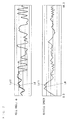
- FIGS. 7 and 8 include diagrams showing the transitions over time of estimated values of the respective parameters in the presence and absence of an offset error in the roll angular velocity sensor 51.
- the roll angular velocity sensor 51, the yaw angular velocity sensor 52, the vertical acceleration sensor 53, the longitudinal acceleration sensor 54, the lateral acceleration sensor 55, and the rear-wheel speed sensor 7, each having no offset error, were attached to the vehicle 100, and estimated values of the respective parameters were calculated on the basis of the detected values of the roll angular velocity sensor 51, the yaw angular velocity sensor 52, the vertical acceleration sensor 53, the longitudinal acceleration sensor 54, the lateral acceleration sensor 55, and the rear-wheel speed sensor 7 that were obtained while the vehicle was actually running. Further, an offset error of 3 deg/s was added to the detected value of the roll angular velocity sensor 51, and the estimated values of the respective parameters were calculated.
- FIG. 7 shows the estimated values of the roll angle ⁇ and the vehicle speed V x
- FIG. 8 shows the estimated values of the roll angular velocity sensor offset b r , the yaw angular velocity sensor offset b y , and the vertical acceleration sensor offset b z .
- the symbol L0 indicates the estimated values of the respective parameters in the case where no offset is added to the roll angular velocity sensor 51, while the symbol Loff indicates the estimated values of the respective parameters in the case where the offset error has been added to the detected value of the roll angular velocity sensor 51.
- the estimated value of the roll angle ⁇ in the case where the offset error has been added to the detected value of the roll angular velocity sensor 51 comes to agree with the estimated value of the roll angle ⁇ in the case where no offset error is added to the detected value of the roll angular velocity sensor 51 in a short period of time. Further, the estimated value of the vehicle speed V x in the case where the offset error has been added to the detected value of the roll angular velocity sensor 51 is substantially equal to the estimated value of the vehicle speed V x in the case where no offset error is added to the detected value of the roll angular velocity sensor 51.
- the difference between the estimated value of the roll angular velocity sensor offset b r in the case where the offset error has been added to the detected value of the roll angular velocity sensor 51 and the estimated value of the roll angular velocity sensor offset br in the case where no offset error is added to the detected value of the roll angular velocity sensor 51 is equal to the value (3 deg/s) of the offset error.
- the roll angle ⁇ can be estimated with high accuracy even in the case where the roll angular velocity sensor 51 has an offset error.
- the roll angle estimation device 10 of the present embodiment the roll angle ⁇ and the vehicle speed V x , as well as the roll angular velocity sensor offset b r , the yaw angular velocity sensor offset b y , and the vertical acceleration sensor offset b z are estimated, and the estimated values of the roll angular velocity sensor offset b r , the yaw angular velocity sensor offset b y , and the vertical acceleration sensor offset b z are used in a next estimation operation.
- This compensates the degradation in estimation accuracy of the roll angle ⁇ due to the roll angular velocity sensor offset b r , the yaw angular velocity sensor offset b y , and the vertical acceleration sensor offset b z .
- the roll angle ⁇ can be estimated with high accuracy.
- the estimated values of the offset errors of the roll angular velocity sensor 51 and the yaw angular velocity sensor 52 which are susceptible to offsets compared to the acceleration sensors, are used in the next estimation operation. This sufficiently improves the estimation accuracy of the roll angle ⁇ .
- the estimated value of the offset error of the vertical acceleration sensor 53 is used in the next estimation operation. This further improves the estimation accuracy of the roll angle ⁇ in the range where the roll angle ⁇ is small.
- the detected value of the rear-wheel speed V r is used in an estimation operation. This makes it possible to estimate the roll angle ⁇ of the vehicle body 1, the roll angular velocity sensor offset b r , the yaw angular velocity sensor offset by, the vertical acceleration sensor offset b z , and the vehicle speed V x with high accuracy even in the case where the vehicle 100 turns in a small radius and at a low speed
- the roll angle ⁇ of the vehicle body 1 is estimated with high accuracy by the roll angle estimation device 10. This ensures that the navigation system 12 and the headlight driving device 15 operate with precision on the basis of the roll angle ⁇ estimated by the ECU 20.
- the turning radius of the front wheel 2 is greater than the turning radius of the rear wheel 3. Consequently, the rotational speed of the front wheel 2 detected by the front-wheel speed sensor 6 is higher than the rotational speed of the rear wheel 3.
- the ECU 20 estimates the rear-wheel speed V r from the rotational speed of the front wheel 2 detected by the front-wheel speed sensor 6.
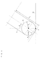
- FIG. 10 is a diagram showing the turning radii of the front wheel 2 and the rear wheel 3 during the turning of the vehicle 100. From the above assumption (c), the sideslip speed of the rear wheel 3 is 0. Therefore, between the turning radius r f of the front wheel 2 and the turning radius r r of the rear wheel 3, the following relationship holds:
- the turning radius r r of the rear wheel 3 is expressed, using the speed V r at the ground contact point of the rear wheel 3 and the roll angle ⁇ , by the following expression:
- g represents the magnitude of the gravitational acceleration.
- V r V f 2 + V f 4 - 4 ⁇ La 2 ⁇ g 2 ⁇ tan 2 ⁇ ⁇ 2
- the condition represented by the above expression (25) may not be satisfied when the turning radius of the vehicle 100 is small.
- the above expression (24) is modified as follows
- V r ⁇ V f 2 + V f 4 - 4 ⁇ La 2 ⁇ g 2 ⁇ tan 2 ⁇ ⁇ 2 when V f 4 ⁇ 4 ⁇ La 2 ⁇ g 2 ⁇ tan 2 ⁇ ⁇ V f 2 when V f 4 ⁇ 4 ⁇ La 2 ⁇ g 2 ⁇ tan 2 ⁇ ⁇
- FIG. 11 is a diagram showing the calculation results of the relationship between the front-wheel speed v f and the rear-wheel speed v r .
- the horizontal axis represents rear-wheel speed v r
- the vertical axis represents front-wheel speed v f .
- the roll angle ⁇ of the vehicle body 1, the vehicle speed V x , the roll angular velocity sensor offset b r , the yaw angular velocity sensor offset b y , and the vertical acceleration sensor offset b z can be estimated with high accuracy, as in the case where the rear-wheel speed sensor 7 is provided.
- the roll angular velocity sensor 51 and the yaw angular velocity sensor 52 in the above embodiment may be replaced with two or more angular velocity sensors that detect angular velocities about two or more axes extending in directions other than the frontward-and-backward direction and the up-and-down direction of the vehicle 100.
- the detected values of the two or more angular velocity sensors can be converted to a roll angular velocity ⁇ r and a yaw angular velocity ⁇ y in a geometric manner, so that the above expressions (17), (18) can be used.
- an angular velocity sensor for detecting an angular velocity about the axis in a right-and-left direction of the vehicle 100 may be used. This can further improve the estimation accuracy of the roll angle ⁇ .
- the vertical acceleration sensor 53, the longitudinal acceleration sensor 54, and the lateral acceleration sensor 55 in the above embodiment may be replaced with three or more acceleration sensors that detect accelerations in three or more directions other than the up-and-down direction, the frontward-and-backward direction, and the right-and-left direction of the vehicle 100.
- the detected values of the three or more acceleration sensors can be converted to a vertical acceleration G z , a longitudinal acceleration G x , and a lateral acceleration G y in a geometric manner, so that the above expressions (17), (18) can be used.
- the roll angular velocity sensor offset b r and the yaw angular velocity sensor offset b y are estimated by the Kalman filter 80 in the above embodiment, not limited thereto, the roll angular velocity sensor offset b r alone may be estimated, or the yaw angular velocity sensor offset b y alone may be estimated.
- the calculation may be performed by setting the other sensor offset values to zero.
- the calculation may be performed by setting the other sensor offset values to zero.
- a vehicle speed detected by a speed sensor capable of measuring the running speed of the vehicle 100 may be used as one of the input parameters to the Kalman filter 80.
- Kalman filter 80 is implemented by the ECU 20 and the program in the above embodiment, not limited thereto, a part or all of the functions of the Kalman filter 80 may be implemented by hardware such as an electronic circuit.
- the Kalman filter 80 in the above embodiment may be replaced with another adaptive filtering approach
- a leas-mean-square (LMS) adaptive filter or H ⁇ filtering may be used
- the roll angle estimation device 10 While the roll angle estimation device 10 is applied to a motorcycle in the above embodiment, not limited thereto, the roll angle estimation device 10 may be applied to a variety of transport equipment such as a four-wheeled motor vehicle, motor tricycle, or other vehicle, or a ship or vessel.
- transport equipment such as a four-wheeled motor vehicle, motor tricycle, or other vehicle, or a ship or vessel.
- the roll angle ⁇ estimated by the roll angle estimation device 10 is used in the navigation system 12 and the headlight driving device 15 in the above embodiment, not limited thereto, the roll angle ⁇ estimated by the roll angle estimation device 10 may be used for a variety of processing such as another control of the transport equipment.
- the axis in the forward-and-backward direction of the vehicle 100 is an example of the first axis
- the axis in the up-and-down direction of the vehicle 100 is an example of the second axis
- the roll angular velocity ⁇ r is an example of the first angular velocity
- the yaw angular velocity ⁇ y is an example of the second angular velocity
- the roll angular velocity sensor 51 is an example of the first angular velocity detector
- the yaw angular velocity sensor 52 is an example of the second angular velocity detector
- the first direction is an example of the up-and-down direction of the vehicle 100
- the second direction is an example of the forward-and-backward direction of the vehicle 100
- the third direction is an example of the right-and-left direction of the vehicle 100
- the vertical acceleration G z is an example of the first acceleration
- the longitudinal acceleration G x is an example of the second acceleration
- the lateral acceleration G y is an example of the third acceleration
- the vertical acceleration sensor 53 is an example of the first acceleration detector
- the longitudinal acceleration sensor 54 is an example of the second acceleration detector
- the lateral acceleration sensor 55 is an example of the third acceleration detector
- the rear-wheel speed v r or the front-wheel speed v r is an example of the information regarding the moving speed
- the rear-wheel speed sensor 7 or the front-wheel speed sensor 6 is an example of the speed information detector
- the ECU 20 is an example of the estimator
- the vehicle 100 or the vehicle body 1 is an example of the movable object
- the front wheel 2 is an example of the front wheel
- the rear wheel 3 is an example of the rear wheel
- the rear-wheel speed sensor 7 is an example of the rear-wheel speed detector
- the front-wheel speed sensor 6 is an example of the front-wheel rotational speed detector
- the ECU 20 is an example of the rear-wheel rotational speed estimator.
- the low pass filters 63, 64, 65 are examples of the first, second, and third low pass filters
- the Kalman filter 80 implemented by the ECU 20 and the program is an example of the Kalman filter.
- the navigation system 12 or the headlight driving device 15 is an example of the processor.
- the present invention is applicable to estimation of the roll angle of transport equipment etc.
Landscapes
- Engineering & Computer Science (AREA)
- Mechanical Engineering (AREA)
- Physics & Mathematics (AREA)
- Automation & Control Theory (AREA)
- Mathematical Physics (AREA)
- Transportation (AREA)
- Control Of Driving Devices And Active Controlling Of Vehicle (AREA)
- Gyroscopes (AREA)
- Vehicle Body Suspensions (AREA)
Abstract
Description
- The present invention relates to a roll angle estimation device and transport equipment including the same.
- Conventionally, a variety of estimation devices for estimating a roll angle of a motorcycle or other vehicle have been proposed. For example, the aim of a headlight can be controlled on the basis of the roll angle estimated by an estimation device, so that the headlight can emit light in an appropriate direction irrespective of the inclination of the vehicle.
- A vehicle posture estimation device described in
Patent Document 1 estimates a roll angle and a pitch angle on the basis of detected values of longitudinal acceleration, lateral acceleration, vertical acceleration, yaw acceleration, and roll angular velocity of the vehicle motion, and also on the basis of an estimated value of longitudinal vehicle body speed and an estimated value of pitch angular velocity.
[Patent Document 1]JP 2009-73466 A - The conventional estimation device, however, cannot estimate the roll angle of a vehicle with high accuracy. This may cause, for example, the headlight aim to be askew even though the vehicle is not inclined.
- An object of the present invention is to provide a roll angle estimation device that can estimate the roll angle of a movable object with high accuracy, and transport equipment including the same.
- (1) According to an aspect of the present invention, a roll angle estimation device that estimates a roll angle of a movable object includes first and second angular velocity detectors that detect first and second angular velocities, respectively, about first and second axes extending in at least two directions, first, second, and third acceleration detectors that detect first, second, and third accelerations, respectively, in at least three directions, a speed information detector that detects information regarding a moving speed in a traveling direction of the movable object, and an estimator configured to estimate the roll angle of the movable object and also estimate an offset error of at least one of the first and second angular velocity detectors and the first, second, and third acceleration detectors, wherein the estimator estimates the roll angle of the movable object and the at least one offset error on the basis of detected values of the first and second angular velocity detectors, detected values of the first, second, and third acceleration detectors, a detected value of the speed information detector, and an estimated value of the roll angle and an estimated value of the offset error obtained in a previous estimation operation.
- In this roll angle estimation device, the first and second angular velocities about the first and second axes extending in at least two directions are detected by the first and second angular velocity detectors, respectively Further, the first, second, and third accelerations in at least three directions are detected by the first, second, and third acceleration detectors, respectively Furthermore, the information regarding the moving speed in the traveling direction of the movable object is detected by the speed information detector. Then, the roll angle of the movable object is estimated by the estimator, and an offset error of the detected value of at least one detector among the first and second angular velocity detectors and the first, second, and third acceleration detectors is estimated by the estimator.
- In this case, the estimator estimates the roll angle of the movable object and the at least one offset error in a current estimation operation on the basis of the detected values of the first and second angular velocity detectors, the detected values of the first, second, and third acceleration detectors, the detected value of the speed information detector, the estimated value of the roll angle obtained in the previous estimation operation, and the estimated value of the offset error obtained in the previous estimation operation.
- As described above, the offset error is estimated as well as the roll angle, and the estimated value of the offset error is used in a next estimation operation. This compensates the degradation in estimation accuracy of the roll angle due to the offset error of at least one of the first and second angular velocity detectors and the first, second, and third acceleration detectors. As a result, the roll angle can be estimated with high accuracy
- (2) The first and second angular velocity detectors may respectively detect the first and second angular velocities about the first and second axes extending in directions different from each other, and the first, second, and third acceleration detectors may respectively detect the first, second, and third accelerations in first, second, and third directions different from one another.
- In this case, the first and second angular velocities about the first and second axes extending in different directions are detected by the first and second angular velocity detectors, respectively. Further, the first, second, and third accelerations in the first, second, and third directions different from one another are detected by the first, second, and third acceleration detectors, respectively.
- (3) The estimator may estimate an offset error of at least one of the first and second angular velocity detectors as the at least one offset error.
- An angular velocity detector is susceptible to an offset error compared to an acceleration detector. Therefore, the use of the estimated value of the offset error of at least one of the first and second angular velocity detectors in the next estimation operation leads to a sufficiently improved estimation accuracy of the roll angle.
- (4) The estimator may estimate offset errors of the first and second angular velocity detectors as the at least one offset error.
- In this case, the use of the estimated values of the offset errors of the first and second angular velocity detectors in the next estimation operation leads to a further improvement of the estimation accuracy of the roll angle.
- (5) The estimator may further estimate an offset error of at least one of the first, second, and third acceleration detectors as the at least one offset error.
- In this case, the use of the estimated value of the offset error of at least one of the first, second, and third acceleration detectors, in addition to the estimated value of the offset error of at least one of the first and second angular velocity detectors, in the next estimation operation leads to a further improvement of the estimation accuracy of the roll angle.
- (6) The first acceleration may be an acceleration in an up-and-down direction of the movable object, and the estimator may estimate the offset error of the first acceleration detector.
- In the range where the roll angle of the movable object is small, the acceleration in the up-and-down direction of the movable object hardly changes. If the detected value of such an acceleration in the up-and-down direction changes due to the offset error of the first acceleration detector the change in the detected value of the acceleration in the up-and-down direction will largely affect the estimation of the roll angle. Therefore, the use of the estimated value of the offset error of the first acceleration detector in the next estimation operation leads to a further improvement of the estimation accuracy of the roll angle in the range where the roll angle is small.
- (7) The movable object may have a front wheel and a rear wheel, and the speed information detector may include a rear-wheel rotational speed detector that detects a rotational speed of the rear wheel as the information. The estimator may be configured to further estimate a moving speed of the movable object, and may estimate the roll angle of the movable object, the at least one offset error, and the moving speed of the movable object in the current estimation operation on the basis of the detected values of the first and second angular velocity detectors, the detected values of the first, second, and third acceleration detectors, a detected value of the rear-wheel speed detector, the estimated value of the roll angle obtained in the previous estimation operation, the estimated value of the offset error obtained in the previous estimation operation, and an estimated value of the moving speed obtained in the previous estimation operation.
- There is a certain relationship among the moving speed of the movable object, the rotational speed of the rear wheel, and the roll angle of the movable object This allows the moving speed of the movable object to be estimated on the basis of the detected value of the rotational speed of the rear wheel and the estimated value of the roll angle. Therefore, the roll angle of the movable object, the at least one offset error, and the moving speed of the movable object can be estimated in the current estimation operation on the basis of the detected values of the first and second angular velocity detectors, the detected values of the first, second, and third acceleration detectors, the detected value of the rotational speed of the rear wheel, the estimated value of the roll angle obtained in the previous estimation operation, the estimated value of the offset error obtained in the previous estimation operation, and the estimated value of the moving speed obtained in the previous estimation operation.
- In the case where the movable object turns in a small radius and at a low speed, the rotational speed of the rear wheel is closer to the moving speed of the movable object compared to the rotational speed of the front wheel. Therefore, the use of the detected value of the rotational speed of the rear wheel makes it possible to estimate the roll angle of the movable object, the at least one offset error, and the moving speed of the movable object with high accuracy.
- (8) The movable object may have a front wheel and a rear wheel, and the speed information detector may include a front-wheel rotational speed detector that detects a rotational speed of the front wheel, and a rear-wheel rotational speed estimator that estimates, as the information, a rotational speed of the rear wheel from a detected value of the front-wheel rotational speed detector. The estimator may be configured to further estimate a moving speed of the movable object, and may estimate the roll angle of the movable object, the at least one offset error, and the moving speed of the movable object in the current estimation operation on the basis of the detected values of the first and second angular velocity detectors, the detected values of the first, second, and third acceleration detectors, an estimated value of the rear-wheel speed detector, the estimated value of the roll angle obtained in the previous estimation operation, the estimated value of the offset error obtained in the previous estimation operation, and an estimated value of the moving speed obtained in the previous estimation operation.
- In the case where the movable object turns in a small radius and at a low speed, the turning radius of the front wheel is greater than the turning radius of the rear wheel. Consequently, the rotational speed of the front wheel detected by the front-wheel rotational speed detector is higher than the rotational speed of the rear wheel. The rotational speed of the rear wheel is estimated by the rear-wheel rotational speed estimator from the detected value of the front-wheel rotational speed detector. This allows the roll angle of the movable object, the at least one offset error, and the moving speed of the movable object to be estimated with high accuracy in the case where the front-wheel rotational speed detector is provided, as in the case where the rear-wheel rotational speed detector is provided.
- (9) The estimator may include a Kalman filter that estimates the roll angle of the movable object and the at least one offset error in the current estimation operation by using a relationship among the detected values of the first and second angular velocity detectors, the detected values of the first, second, and third acceleration detectors, the detected value of the speed information detector, the estimated value of the roll angle obtained in the previous estimation operation, and the estimated value of the offset error obtained in the previous estimation operation.
- In this case, the estimator can readily be implemented by using the algorithm of the Kalman filter.
- (10) According to another aspect of the present invention, transport equipment includes a movable object configured to be moveable, the roll angle estimation device, according to the above invention, that estimates a roll angle of the movable object, and a processor that performs processing using the roll angle estimated by the roll angle estimation device.
- In this transport equipment, the roll angle of the movable portion is estimated with high accuracy by the roll angle estimation device according to the above invention. This ensures that the processing by the processor using the roll angle is performed with high accuracy.
- According to the present invention, it is possible to estimate the roll angle of a movable object with high accuracy.
-
- [
FIG. 1] FIG. 1 is a schematic view of the vehicle including a roll angle estimation device according to an embodiment of the present invention. - [
FIG. 2] FIG. 2 is a block diagram showing the configuration of the roll angle estimation device according to an embodiment of the present invention. - [
FIG. 3] FIG. 3 is a diagram showing the concept of a Kalman filter. - [
FIG. 4] FIG. 4 is a diagram illustrating the attachment position of a sensor group. - [
FIG. 5] FIG. 5 is a cross-sectional view of the rear wheel. - [
FIG. 6] FIG. 6 is a diagram showing the attachment position of the sensor group in vectors. - [
FIG. 7] FIG. 7 includes diagrams showing the transitions over time of values of respective parameters estimated by the roll angle estimation device. - [
FIG. 8] FIG. 8 includes diagrams showing the transitions over time of estimated values of respective parameters. - [
FIG. 9] FIG. 9 is a schematic view of the vehicle including a roll angle estimation device according to another embodiment of the present invention. - [
FIG. 10] FIG. 10 is a diagram showing the turning radii of the front wheel and the rear wheel during turning of the vehicle. - [
FIG. 11] FIG. 11 is a diagram showing the calculation results of the relationship between the front-wheel speed and the rear-wheel speed. - Description will now be made of an example in which a roll angle estimation device according to an embodiment of the present invention is applied to a vehicle.
-
FIG. 1 is a schematic view of the vehicle including the roll angle estimation device according to an embodiment of the present invention. Thevehicle 100 inFIG. 1 is a motorcycle. - As shown in
FIG. 1 , thevehicle 100 includes avehicle body 1. Thevehicle body 1 has afront wheel 2 attached to the front thereof and arear wheel 3 attached to the rear thereof. Thevehicle body 1 also has asensor group 5 attached to the center thereof. Thesensor group 5 will be described later in detail. - A rear-
wheel speed sensor 7 for detecting the rotational speed of therear wheel 3 is attached to the wheel of therear wheel 3. - At the top on the front side of the
vehicle body 1, ahandlebar 11 is provided so as to be swingable right and left. Anavigation system 12 is provided near thehandlebar 11. Thevehicle body 1 further has aheadlight 14 and aheadlight driving device 15 provided at the front thereof. Theheadlight driving device 15 controls the aim of theheadlight 14. Thevehicle body 1 has an electronic control unit (hereinafter, abbreviated as ECU) 20 provided at the rear thereof. - Signals output from the
sensor group 5 and the rear-wheel speed sensor 7 are fed to theECU 20. TheECU 20 controls the components of thevehicle body 1. TheECU 20 also estimates the roll angle of thevehicle body 1, and feeds the estimated roll angle to, for example, thenavigation system 12 and theheadlight driving device 15. - In the present embodiment, the
sensor group 5, the rear-wheel speed sensor 9, and theECU 20 constitute the roll angle estimation device. -
FIG. 2 is a block diagram showing the configuration of the roll angle estimation device according to an embodiment of the present invention. - The roll
angle estimation device 10 inFIG. 2 is made up of thesensor group 5, the rear-wheel speed sensor 7, low pass filters 61-65,differentiators Kalman filter 80. The functions of theKalman filter 80 are implemented by theECU 20 inFIG. 1 and a program. - The
sensor group 5 includes a rollangular velocity sensor 51, a yawangular velocity sensor 52, avertical acceleration sensor 53, alongitudinal acceleration sensor 54, and alateral acceleration sensor 55. - The roll
angular velocity sensor 51 is disposed on thevehicle body 1 so as to detect the roll angular velocity of thevehicle body 1. The roll angular velocity refers to the angular velocity about a longitudinal axis of thevehicle 100. The yawangular velocity sensor 52 is disposed on thevehicle body 1 so as to detect the yaw angular velocity of thevehicle body 1. The yaw angular velocity refers to the angular velocity about a vertical axis of thevehicle 100. - The
vertical acceleration sensor 53 is disposed on thevehicle body 1 so as to detect the vertical acceleration of thevehicle body 1. The vertical acceleration refers to the acceleration in an up-and-down direction of thevehicle body 1. Thelongitudinal acceleration sensor 54 is disposed on thevehicle body 1 so as to detect the longitudinal acceleration of thevehicle body 1. The longitudinal acceleration refers to the acceleration in a forward-and-backward direction of thevehicle body 1. Thelateral acceleration sensor 55 is disposed on thevehicle body 1 so as to detect the lateral acceleration of thevehicle body 1. The lateral acceleration refers to the acceleration in a right-and-left direction of thevehicle body 1. - The signal output from the roll
angular velocity sensor 51 is fed through thelow pass filter 61 to theKalman filter 80 and thedifferentiator 71 as a roll angular velocity. Thelow pass filter 61 removes noise from the output signal of the rollangular velocity sensor 51. Thedifferentiator 71 feeds a differential value of the roll angular velocity, as a roll angular acceleration, to theKalman filter 80. The signal output from the yawangular velocity sensor 52 is fed through thelow pass filter 62 to theKalman filter 80 and thedifferentiator 72 as a yaw angular velocity. Thelow pass filter 62 removes noise from the output signal of the yawangular velocity sensor 52. Thedifferentiator 72 feeds a differential value of the yaw angular velocity, as a yaw angular acceleration, to theKalman filter 80. - The signal output from the
vertical acceleration sensor 53 is fed through thelow pass filter 63 to theKalman filter 80 as a vertical acceleration. The signal output from thelongitudinal acceleration sensor 54 is fed through thelow pass filter 64 to theKalman filter 80 as a longitudinal acceleration. The signal output from thelateral acceleration sensor 55 is fed through thelow pass filter 65 to theKalman filter 80 as a lateral acceleration. - The signal output from the rear-
wheel speed sensor 7 is fed to theKalman filter 80 as a rear-wheel speed. The rear-wheel speed refers to the rotational speed at the outermost periphery of the tire of therear wheel 3 on the assumption that there is no slip between the road surface and the tire. The rear-wheel speed is practically calculated on the basis of the output signal from the rear-wheel speed sensor 7 and the tire size. For simplification of the explanation, it is assumed inFIG. 2 that the rear-wheel speed sensor 7 outputs a signal that indicates the rear-wheel speed - Here, the roll angular velocity, roll angular acceleration, yaw angular velocity, yaw angular acceleration, vertical acceleration, longitudinal acceleration, lateral acceleration, and rear-wheel speed are denoted by the symbols shown in the following table. It is noted that a single dot placed at the top of the symbol representing a parameter indicates first order differentiation.
-
[Table 1] Parameter Meaning ωr Roll Angular Velocity ω̇r Roll Angular Acceleration ωy Yaw Angular Velocity ω̇y Yaw Angular Acceleration Gz Vertical Acceleration Gx Longitudinal Acceleration Gy Lateral Acceleration υr Rear-Wheel Speed - On the basis of the above parameters, the
Kalman filter 80 estimates and outputs the roll angle, vehicle speed, roll angular velocity sensor offset, yaw angular velocity sensor offset, and vertical acceleration sensor offset. - Here, the vertical plane parallel to the traveling direction of the
vehicle 100 is called the longitudinal vertical plane, and the vertical plane perpendicular to the longitudinal vertical plane is called the lateral vertical plane. The roll angle refers to the tilt angle of thevehicle body 1 with respect to the direction of gravity in the lateral vertical plane. The vehicle speed refers to the speed in the traveling direction of thevehicle body 1. - The roll angular velocity sensor offset refers to the offset error of the roll
angular velocity sensor 51. The yaw angular velocity sensor offset refers to the offset error of the yawangular velocity sensor 52. The vertical acceleration sensor offset refers to the offset error of thevertical acceleration sensor 53. - The vehicle speed, roll angular velocity sensor offset, yaw angular velocity sensor offset, and vertical acceleration sensor offset are denoted by the symbols shown in the following table.
-
[Table 2] Parameter Meaning φ Roll Angle Vx Vehicle Speed br Roll Angular Velocity Sensor Offset by Yaw Angular Velocity Sensor Offset bz Vertical Acceleration Sensor Offset - In the roll
angle estimation device 10 according to the present embodiment, the rollangular velocity sensor 51, the yawangular velocity sensor 52, thevertical acceleration sensor 53, thelongitudinal acceleration sensor 54, thelateral acceleration sensor 55, and the rear-wheel speed sensor 7 are used to derive five relational expressions in expressions (17), (18), which will be described later. Using these relational expressions, two parameters of roll angle φ and vehicle speed Vx are estimated. That is, there exists redundancy between the number of relational expressions and the number of outputs to be estimated. In other words, the number of relational expressions is greater than the number of outputs to be estimated. The use of this redundancy makes it possible to estimate the roll angular velocity sensor offset br, the yaw angular velocity sensor offset by, and the vertical acceleration sensor offset bz. -
FIG. 3 is a diagram showing the concept of theKalman filter 80. TheKalman filter 80 inFIG. 3 uses a kinematic model of thevehicle 100 as described below. - In
FIG. 3 , theKalman filter 80 is made up of a system equation 8a, an addingfunction 8b, an integratingfunction 8c, anobservation equation 8d, asubtracting function 8e, and aKalman gain 8f. The system equation 8a includes the function f(x, u). Theobservation equation 8d includes the function h(x). TheKalman gain 8f includes a fifth-order Kalman gain K - In a current estimation operation, a detected value of the roll angular velocity ωr, a detected value of the roll angular acceleration (differential value of the roll angular velocity ωr), a detected value of the yaw angular velocity ωy, the yaw angular acceleration (differential value of the yaw angular velocity ωy), and a detected value of the longitudinal acceleration Gx are given as input parameters u to the system equation 8a. Further, the estimated value of the roll angle φ, the estimated value of the vehicle speed Vx, the estimated value of the roll angular velocity sensor offset br, the estimated value of the yaw angular velocity sensor offset by, and the estimated value of the vertical acceleration sensor offset hz obtained in the previous estimation operation are given as input parameters x to the system equation 8a. The system equation 8a outputs a differential value of the roll angle φ, a differential value of the vehicle speed Vx, a differential value of the roll angular velocity sensor offset br, a differential value of the yaw angular velocity sensor offset by, and a differential value of the vertical acceleration sensor offset hz.
- To the differential value of the roll angle φ, the differential value of the vehicle speed Vx, the differential value of the roll angular velocity sensor offset br, the differential value of the yaw angular velocity sensor offset by, and the differential value of the vertical acceleration sensor offset bz, a fifth-order Kalman gain K obtained in the previous estimation operation is added.
- The differential value of the roll angle φ, the differential value of the vehicle speed Vx, the differential value of the roll angular velocity sensor offset br, the differential value of the yaw angular velocity sensor offset by, and the differential value of the vertical acceleration sensor offset bz, with the Kalman gain K added thereto, are integrated, so that an estimated value of the roll angle φ, an estimated value of the vehicle speed Vx, an estimated value of the roll angular velocity sensor offset br, an estimated value of the yaw angular velocity sensor offset by, and an estimated value of the vertical acceleration sensor offset bz according to the current estimation operation are obtained.
- Further, the estimated value of the roll angle φ, the estimated value of the vehicle speed Vx, the estimated value of the roll angular velocity sensor offset br, the estimated value of the yaw angular velocity sensor offset by, and the estimated value of the vertical acceleration sensor offset bz are given as input parameters x to the
observation equation 8d. From theobservation equation 8d, a calculated value of the vertical acceleration Gz, a calculated value of the lateral acceleration Gy, and a calculated value of the rear-wheel speed vr are obtained. - Further, a detected value of the vertical acceleration Gz, a detected value of the lateral acceleration Gy, and a detected value of the rear-wheel speed vr are given as input parameters y to the
Kalman filter 80. The Kalman gain K is calculated on the basis of the differences between the detected values and the calculated values of the vertical acceleration Gz, the lateral acceleration Gy, and the rear-wheel speed vr. - Deriving the system equation 8a and the
observation equation 8d in this kinematic model makes it possible to derive relational expressions of the input parameters u, y and the output parameters x - In the present embodiment, for simplification of the kinematic model, the following assumptions are made:
- (a) The
vehicle 100 does not pitch. - (b) There is no slip in the rotational direction between the
rear wheel 3 and the road surface. - (c) The sideslip speed of the
rear wheel 3 is 0. - (d) The road surface is flat and has no slope.
- On the basis of these assumptions (a)-(d), the kinematic model formulae are derived in the following manner.
- The roll angle, differential value of the roll angle, pitch angle, differential value of the pitch angle, yaw angle, differential value of the yaw angle, roll angular velocity, yaw angular velocity, and pitch angular velocity are denoted by the symbols shown in the following table.
-
[Table 3] Parameter Meaning φ Roll Angle φ Differential Value of Roll Angle θ Pitch Angle θ̇ Differential Value of Pitch Angle ψ Yaw Angle ψ̇ Differential Value of Yaw Angle ωr Roll Angular Velocity ωy Pitch Angular Velocity ωp Yaw Angular Velocity - First, from a general relational expression of Euler angles and angular velocities, the following expression holds:
-

- From the above assumption (a), the pitch angle and its differential value both take a value of 0. Therefore, the above expression (1) gives the following expression:
-

- The pitch angular velocity ωp can be deleted from the second row of the above expression (2). This results in the following expression:
-

-
FIG. 4 is a diagram illustrating the attachment position of thesensor group 5. InFIG. 4 , the left side of thevehicle 100 is shown on the left, and the front of thevehicle 100 is shown on the right.FIG. 5 is a cross-sectional view of therear wheel 3.FIG. 6 is a diagram showing the attachment position of thesensor group 5 in vectors. - In
FIG. 4 , the attachment position of thesensor group 5 is denoted PS. The horizontal distance from the attachment position PS to the center of therear wheel 3 is denoted L, and the height from the road surface to the attachment position PS is denoted h. - In
FIG. 5 , therear wheel 3 is tilted by a roll angle φ with respect to the road surface RD. The road surface RD has no slope, from the above assumption (d). The contact point between the tire TR of therear wheel 3 and the road surface RD is denoted P. Further, the radius of the cross section of the tire TR of therear wheel 3 is denoted Rcr, and the radius of therear wheel 3 is denoted Re. - In
FIG. 6 , the position vector of the attachment position PS of thesensor group 5 with respect to the origin O of the inertial coordinate system is denoted rv, the position vector of the ground contact point P with respect to the origin O of the inertial coordinate system is denoted rv0, and the vector from the ground contact point P to the attachment position PS of thesensor group 5 is denoted ρv. In this case, the following holds: rv=rv0+ρv. - Here, the second-order differential vector of the position vector rv, second-order differential vector of the position vector rv0, second-order differential vector of the vector pv, and gravitational acceleration vector are denoted by the symbols shown in the following table. It is noted that two dots placed at the top of the symbol representing a parameter indicate second order differentiation.
-
[Table 4] Parameter Meaning ṙ v̇ Second-Order Differential Vector of Position Vector rv ṙ v̇ 0 Second-Order Differential Vector of Position Vector rvo ρ̇ v̇ Second-Order Differential Vector of Attachment Position Vector ρv g v Gravitational Acceleration Vector - Here, the acceleration vector detected by the
vertical acceleration sensor 53, thelongitudinal acceleration sensor 54, and thelateral acceleration sensor 55 at the attachment position PS is denoted Gv. The acceleration vector Gv is obtained by adding the gravitational acceleration vector to the second-order differential vector of the position vector rv, as in the following expression: -

- The right side of the above expression (4) will now be calculated. The vector pv in
FIG. 6 is represented by the following expression: -

- In the above expression (5), [e]=[e1, e2, e3] e1, e2, and e3 are base vectors fixed to the
vehicle body 1, where e1 is the base vector in a forward direction of thevehicle body 1, e2 is the base vector in a leftward direction of thevehicle body 1, and e3 is the base vector in a vertically upward direction of thevehicle body 1. Further, ρ represents a matrix. FromFIGS. 4 and5 , the matrix ρ in the above expression (5) is represented by the following expression: -

- From the above expression (6), the second-order differential vector of the vector ρv is found as in the following expression:
-

- In the above expression (7), ax, ay, and az are functions. The functions ax, ay, az can be found by calculating the above expressions (5) and (6). On the transformation from the above expression (6) to the above expression (7), the above expression (3) can be used to eliminate the differential value of the roll angle φ and the differential value of the yaw angle ψ.
- Next, the sideslip speed of the
vehicle 100 is denoted Vy. Using the vehicle speed Vx and the sideslip speed Vy, the first-order differential vector of the position vector rv0 inFIG. 6 is represented by the following expression: -

- In the above expression (8), [e0]=[e01, e02, e03]. e01, e02, and e03 are base vectors that are obtained by rotating the base vectors [e]=[e1, e2, e3] in the inertial coordinate system by only a yaw angle ψ.
- From the assumption (c), Vy=0. When the above expression (8) is subjected to first order differentiation, the second-order differential vector of the position vector rv0 is represented by the following expression:
-

- Lastly, the gravitational acceleration vector is represented by the following expression:
-

- In the above expression (10), g represents the magnitude of the gravitational acceleration.
- From the above expressions (4), (7), (9), and (10), the acceleration vector Gv detected at the attachment position PS is represented by the following expression:
-

- Here, using the longitudinal acceleration Gx detected by the
longitudinal acceleration sensor 54, the lateral acceleration Gy detected by thelateral acceleration sensor 55, and the vertical acceleration Gz detected by thevertical acceleration sensor 53, the acceleration vector Gv detected at the attachment position PS is represented by the following expression: - Gv=[e][Gx, Gy, Gz]
Therefore, from the above expression (11), the longitudinal acceleration Gx, the lateral acceleration Gy detected by thelateral acceleration sensor 55, and the vertical acceleration Gz detected by thevertical acceleration sensor 53 become as follows: -

- Next, the relationship between the rear-wheel speed vr and the vehicle speed Vx is found. From the above assumption (b), there is no slip between the
rear wheel 3 and the road surface. Therefore, fromFIG. 5 , the following relationship holds between the rear-wheel speed Vr and the vehicle speed Vx: -

- From the above expression (13), the following expression is found:
-

- From the above expressions (3), (12), and (14), the following expressions are found:
-

-

- The use of the above expression (15) as the system equation and the above expression (16) as the observation equation enables application of an extended Kalman filter,
- Further, even when the roll angular velocity sensor offset br, the yaw angular velocity sensor offset by, and the vertical acceleration sensor offset bz change, the changes in their values are slow compared to the motion of the
vehicle 100. Therefore, the differential value of the roll angular velocity sensor offset br, the differential value of the yaw angular velocity sensor offset by, and the differential value of the vertical acceleration sensor offset bz can each be regarded as 0. - Furthermore, by replacing the roll angular velocity ωr, the yaw angular velocity ωy, and the vertical accelerations Gz in the above expressions (15), (16) by ωr-br, ωy-by, and Gz-bz, respectively, the following expressions can be derived:
-

-

- In the above expressions (17), (18), the roll angular velocity sensor offset br, the yaw angular velocity sensor offset by, and the vertical acceleration sensor offset bz are taken into consideration
- Application of the extended Kalman filter by using the above expression (17) as the system equation and the above expression (18) as the observation equation enables estimation of the roll angle φ, the vehicle speed Vx, the roll angular velocity senor offset br, the yaw angular velocity sensor offset by, and the vertical acceleration sensor offset bz.
- Here, the right side of the above expression (17) corresponds to the function f(x, u) in
FIG. 3 , and the right side of the above expression (18) corresponds to the function h(x) inFIG. 3 . - An angular velocity sensor is susceptible to an offset error compared to an acceleration sensor. Therefore, in the present embodiment, an offset error of the roll angular velocity sensor 51 (roll angular velocity sensor offset br) and an offset error of the yaw angular velocity sensor 52 (yaw angular velocity sensor offset by) are estimated. The use of the estimated values of the roll angular velocity sensor offset br and the yaw angular velocity sensor offset by in a next estimation operation sufficiently improves the estimation accuracy of the roll angle φ.
- Further, if offset errors of the three acceleration sensors (
vertical acceleration sensor 53,longitudinal acceleration sensor 54, and lateral acceleration sensor 55) can be estimated, it will lead to a further improvement in the estimation accuracy of the roll angle φ. When estimating the offset errors of the three acceleration sensors, however, observablity cannot be maintained. Therefore, in the present embodiment, an offset error of the vertical acceleration sensor 53 (vertical acceleration sensor offset bz) is estimated for the following reason. In the range where the roll angle φ of thevehicle body 1 is small, the vertical acceleration of thevehicle body 1 hardly changes. If the detected value of such a vertical acceleration changes due to the vertical acceleration sensor offset bz, the change in the detected value of the vertical acceleration will largely affect the estimation of the roll angle φ. Therefore, the estimated value of the vertical acceleration sensor offset bz is used in a next estimation operation, to further improve the estimation accuracy of the roll angle φ in the range where the roll angle φ is small. -
FIGS. 7 and8 include diagrams showing the transitions over time of estimated values of the respective parameters in the presence and absence of an offset error in the rollangular velocity sensor 51. - Here, the roll
angular velocity sensor 51, the yawangular velocity sensor 52, thevertical acceleration sensor 53, thelongitudinal acceleration sensor 54, thelateral acceleration sensor 55, and the rear-wheel speed sensor 7, each having no offset error, were attached to thevehicle 100, and estimated values of the respective parameters were calculated on the basis of the detected values of the rollangular velocity sensor 51, the yawangular velocity sensor 52, thevertical acceleration sensor 53, thelongitudinal acceleration sensor 54, thelateral acceleration sensor 55, and the rear-wheel speed sensor 7 that were obtained while the vehicle was actually running. Further, an offset error of 3 deg/s was added to the detected value of the rollangular velocity sensor 51, and the estimated values of the respective parameters were calculated.FIG. 7 shows the estimated values of the roll angle φ and the vehicle speed Vx, andFIG. 8 shows the estimated values of the roll angular velocity sensor offset br, the yaw angular velocity sensor offset by, and the vertical acceleration sensor offset bz. - The symbol L0 indicates the estimated values of the respective parameters in the case where no offset is added to the roll
angular velocity sensor 51, while the symbol Loff indicates the estimated values of the respective parameters in the case where the offset error has been added to the detected value of the rollangular velocity sensor 51. - As shown in
FIG. 7 , the estimated value of the roll angle φ in the case where the offset error has been added to the detected value of the rollangular velocity sensor 51 comes to agree with the estimated value of the roll angle φ in the case where no offset error is added to the detected value of the rollangular velocity sensor 51 in a short period of time. Further, the estimated value of the vehicle speed Vx in the case where the offset error has been added to the detected value of the rollangular velocity sensor 51 is substantially equal to the estimated value of the vehicle speed Vx in the case where no offset error is added to the detected value of the rollangular velocity sensor 51. - As shown in
FIG. 8 , the difference between the estimated value of the roll angular velocity sensor offset br in the case where the offset error has been added to the detected value of the rollangular velocity sensor 51 and the estimated value of the roll angular velocity sensor offset br in the case where no offset error is added to the detected value of the rollangular velocity sensor 51 is equal to the value (3 deg/s) of the offset error. - It is noted that the estimated values of the yaw angular velocity sensor offset by and the vertical acceleration sensor offset bz were almost 0 irrespective of whether the offset error was added to the detected value of the roll
angular velocity sensor 51 or not - It is apparent from the above description that according to the roll
angle estimation device 10 of the present embodiment, the roll angle φ can be estimated with high accuracy even in the case where the rollangular velocity sensor 51 has an offset error. - According to the roll
angle estimation device 10 of the present embodiment, the roll angle φ and the vehicle speed Vx, as well as the roll angular velocity sensor offset br, the yaw angular velocity sensor offset by, and the vertical acceleration sensor offset bz are estimated, and the estimated values of the roll angular velocity sensor offset br, the yaw angular velocity sensor offset by, and the vertical acceleration sensor offset bz are used in a next estimation operation. This compensates the degradation in estimation accuracy of the roll angle φ due to the roll angular velocity sensor offset br, the yaw angular velocity sensor offset by, and the vertical acceleration sensor offset bz. As a result, the roll angle φ can be estimated with high accuracy. - Further, the estimated values of the offset errors of the roll
angular velocity sensor 51 and the yawangular velocity sensor 52, which are susceptible to offsets compared to the acceleration sensors, are used in the next estimation operation. This sufficiently improves the estimation accuracy of the roll angle φ. - Furthermore, the estimated value of the offset error of the
vertical acceleration sensor 53 is used in the next estimation operation. This further improves the estimation accuracy of the roll angle φ in the range where the roll angle φ is small. - Further, the detected value of the rear-wheel speed Vr, detected by the rear-
wheel speed sensor 7, is used in an estimation operation. This makes it possible to estimate the roll angle φ of thevehicle body 1, the roll angular velocity sensor offset br, the yaw angular velocity sensor offset by, the vertical acceleration sensor offset bz, and the vehicle speed Vx with high accuracy even in the case where thevehicle 100 turns in a small radius and at a low speed - As described above, the roll angle φ of the
vehicle body 1 is estimated with high accuracy by the rollangle estimation device 10. This ensures that thenavigation system 12 and theheadlight driving device 15 operate with precision on the basis of the roll angle φ estimated by theECU 20. -
- (a) In the roll
angle estimation device 10 according to the above embodiment, the rear-wheel speed sensor 7 for detecting the rotational speed of therear wheel 3 is attached to the wheel of therear wheel 3. Alternatively, as shown inFIG. 9 , instead of the rear-wheel speed sensor 7, a front-wheel speed sensor 6 for detecting the rotational speed of thefront wheel 2 may be attached to the wheel of thefront wheel 2.FIG. 9 is a schematic view of the vehicle including the roll angle estimation device according to another embodiment of the present invention. More specifically, while the rear-wheel speed Vr detected by the rear-wheel speed sensor 7 is used in the above embodiment instead of the rear-wheel speed Vr detected by the rear-wheel speed sensor 7, the front-wheel speed detected by the front-wheel speed sensor 6 shown inFIG. 9 may be used to estimate the rear-wheel speed Vr therefrom. - In the case where the
vehicle 100 turns in a small radius and at a low speed, the turning radius of thefront wheel 2 is greater than the turning radius of therear wheel 3. Consequently, the rotational speed of thefront wheel 2 detected by the front-wheel speed sensor 6 is higher than the rotational speed of therear wheel 3. TheECU 20 estimates the rear-wheel speed Vr from the rotational speed of thefront wheel 2 detected by the front-wheel speed sensor 6. -
FIG. 10 is a diagram showing the turning radii of thefront wheel 2 and therear wheel 3 during the turning of thevehicle 100. From the above assumption (c), the sideslip speed of therear wheel 3 is 0. Therefore, between the turning radius rf of thefront wheel 2 and the turning radius rr of therear wheel 3, the following relationship holds: -

- Here, La denotes the wheel base length of the
vehicle 100. From the above expression (19), the following expression is obtained: -

- The ratio between the speed Vf at the ground contact point of the
front wheel 2 and the speed Vr at the ground contact point of therear wheel 3 is equal to that between the turning radius rf of thefront wheel 2 and the turning radius rr of therear wheel 3. Therefore, the following expression holds: -

- Furthermore, assuming that the
vehicle 100 is turning steadily, the turning radius rr of therear wheel 3 is expressed, using the speed Vr at the ground contact point of therear wheel 3 and the roll angle φ, by the following expression: -

- In the above expression (22), g represents the magnitude of the gravitational acceleration. When the above expression (22) is substituted in the above expression (21), the following expression is derived:
-

- From the above expression (23), the speed Vr at the ground contact point of the
rear wheel 3 is represented by the following expression: -

- The above expression (24) has a solution only when the condition represented by the following expression is satisfied:
-

- The condition represented by the above expression (25) may not be satisfied when the turning radius of the
vehicle 100 is small. In order to ensure that there is a solution even in such a case, the above expression (24) is modified as follows -

- For the roll angle φ in the above expression (26), the estimated value of the roll angle φ obtained in the previous estimation operation is used.
- From the above expression (26), the relationship between the speed Vf at the ground contact point of the
front wheel 2 and the speed Vr at the ground contact point of therear wheel 3 is found. Accordingly, it is possible to calculate the rear-wheel speed vr from the rotational speed of the front wheel 2 (hereinafter, referred to as the front-wheel speed vf) detected by the front-wheel speed sensor 6. -
FIG. 11 is a diagram showing the calculation results of the relationship between the front-wheel speed vf and the rear-wheel speed vr. InFIG. 10 , the horizontal axis represents rear-wheel speed vr, and the vertical axis represents front-wheel speed vf. - As shown in
FIG. 11 , it is possible to estimate the rear-wheel speed vr from the front-wheel speed vf detected by the front-wheel speed sensor 6. Therefore, even in the case where the front-wheel speed sensor 6 alone is provided, the roll angle φ of thevehicle body 1, the vehicle speed Vx, the roll angular velocity sensor offset br, the yaw angular velocity sensor offset by, and the vertical acceleration sensor offset bz can be estimated with high accuracy, as in the case where the rear-wheel speed sensor 7 is provided. - (b) The roll
angular velocity sensor 51 and the yawangular velocity sensor 52 in the above embodiment may be replaced with two or more angular velocity sensors that detect angular velocities about two or more axes extending in directions other than the frontward-and-backward direction and the up-and-down direction of thevehicle 100. In this case, the detected values of the two or more angular velocity sensors can be converted to a roll angular velocity ωr and a yaw angular velocity ωy in a geometric manner, so that the above expressions (17), (18) can be used. - (c) In addition to the roll
angular velocity sensor 51 and the yawangular velocity sensor 52 in the above embodiment, an angular velocity sensor for detecting an angular velocity about the axis in a right-and-left direction of thevehicle 100 may be used. This can further improve the estimation accuracy of the roll angle φ. - (d) The
vertical acceleration sensor 53, thelongitudinal acceleration sensor 54, and thelateral acceleration sensor 55 in the above embodiment may be replaced with three or more acceleration sensors that detect accelerations in three or more directions other than the up-and-down direction, the frontward-and-backward direction, and the right-and-left direction of thevehicle 100. In this case, the detected values of the three or more acceleration sensors can be converted to a vertical acceleration Gz, a longitudinal acceleration Gx, and a lateral acceleration Gy in a geometric manner, so that the above expressions (17), (18) can be used. - (e) While the roll angular velocity sensor offset br and the yaw angular velocity sensor offset by are estimated by the
Kalman filter 80 in the above embodiment, not limited thereto, the roll angular velocity sensor offset br alone may be estimated, or the yaw angular velocity sensor offset by alone may be estimated. In the case of estimating only the roll angular velocity sensor offset br, the calculation may be performed by setting the other sensor offset values to zero. Similarly, in the case of estimating only the yaw angular velocity sensor offset by, the calculation may be performed by setting the other sensor offset values to zero. - (f) While the vertical acceleration sensor offset bz is estimated in the above embodiment, not limited thereto, an offset error of the
longitudinal acceleration sensor 54 may be estimated, or an offset error of thelateral acceleration sensor 55 may be estimated. - (g) While the rear-wheel speed vr is used as one of the input parameters to the
Kalman filter 80 in the above embodiment not limited thereto, a vehicle speed detected by a speed sensor capable of measuring the running speed of the vehicle 100 (vehicle speed) may be used as one of the input parameters to theKalman filter 80. - (h) While the vehicle speed Vx is estimated by the
Kalman filter 80 in the above embodiment, for example in the case where the vehicle speed is detected by a speed sensor, the vehicle speed Vx does not have to be estimated by theKalman filter 80. - (i) While the
Kalman filter 80 is implemented by theECU 20 and the program in the above embodiment, not limited thereto, a part or all of the functions of theKalman filter 80 may be implemented by hardware such as an electronic circuit. - (j) The
Kalman filter 80 in the above embodiment may be replaced with another adaptive filtering approach For example, a leas-mean-square (LMS) adaptive filter or H ∞ filtering may be used - (k) While the roll
angle estimation device 10 is applied to a motorcycle in the above embodiment, not limited thereto, the rollangle estimation device 10 may be applied to a variety of transport equipment such as a four-wheeled motor vehicle, motor tricycle, or other vehicle, or a ship or vessel. - (I) While the roll angle φ estimated by the roll
angle estimation device 10 is used in thenavigation system 12 and theheadlight driving device 15 in the above embodiment, not limited thereto, the roll angle φ estimated by the rollangle estimation device 10 may be used for a variety of processing such as another control of the transport equipment. - In the following paragraphs, non-limiting examples of correspondences between various elements recited in the claims below and those described above with respect to various preferred embodiments of the present invention are explained.
- In the embodiments described above, the axis in the forward-and-backward direction of the
vehicle 100 is an example of the first axis, the axis in the up-and-down direction of thevehicle 100 is an example of the second axis, the roll angular velocity ωr is an example of the first angular velocity, the yaw angular velocity ωy is an example of the second angular velocity, the rollangular velocity sensor 51 is an example of the first angular velocity detector, and the yawangular velocity sensor 52 is an example of the second angular velocity detector - Further, the first direction is an example of the up-and-down direction of the
vehicle 100, the second direction is an example of the forward-and-backward direction of thevehicle 100, the third direction is an example of the right-and-left direction of thevehicle 100, the vertical acceleration Gz is an example of the first acceleration, the longitudinal acceleration Gx is an example of the second acceleration, the lateral acceleration Gy is an example of the third acceleration, thevertical acceleration sensor 53 is an example of the first acceleration detector, thelongitudinal acceleration sensor 54 is an example of the second acceleration detector, and thelateral acceleration sensor 55 is an example of the third acceleration detector - Furthermore, the rear-wheel speed vr or the front-wheel speed vr is an example of the information regarding the moving speed, the rear-
wheel speed sensor 7 or the front-wheel speed sensor 6 is an example of the speed information detector, and theECU 20 is an example of the estimator - Further, the
vehicle 100 or thevehicle body 1 is an example of the movable object, thefront wheel 2 is an example of the front wheel, therear wheel 3 is an example of the rear wheel, the rear-wheel speed sensor 7 is an example of the rear-wheel speed detector, the front-wheel speed sensor 6 is an example of the front-wheel rotational speed detector, and theECU 20 is an example of the rear-wheel rotational speed estimator. - Further, the low pass filters 63, 64, 65 are examples of the first, second, and third low pass filters, and the
Kalman filter 80 implemented by theECU 20 and the program is an example of the Kalman filter. Thenavigation system 12 or theheadlight driving device 15 is an example of the processor. - As the elements recited in the claims, a variety of other elements having the configuration or function recited in the claims may be used as well.
- The present invention is applicable to estimation of the roll angle of transport equipment etc.
Claims (10)
- A roll angle estimation device that estimates a roll angle of a movable object, the device comprising:first and second angular velocity detectors that detect first and second angular velocities, respectively, about first and second axes extending in at least two directions different from each other;first, second, and third acceleration detectors that detect first, second, and third accelerations, respectively, in at least three directions different from one another;a speed information detector that detects information regarding a moving speed in a traveling direction of said movable object; andan estimator configured to estimate the roll angle of said movable object and also estimate an offset error of at least one of said first and second angular velocity detectors and said first, second, and third acceleration detectors,said estimator estimating the roll angle of said movable object and said at least one offset error in a current estimation operation on the basis of detected values of said first and second angular velocity detectors, detected values of said first, second, and third acceleration detectors, a detected value of said speed information detector, an estimated value of the roll angle obtained in a previous estimation operation, and an estimated value of the offset error obtained in the previous estimation operation.
- The roll angle estimation device according to claim 1, wherein
said first and second angular velocity detectors respectively detect the first and second angular velocities about the first and second axes extending in two directions different from each other, and
said first, second, and third acceleration detectors respectively detect the first, second, and third accelerations in three directions different from one another. - The roll angle estimation device according to claim 1, wherein said estimator estimates an offset error of at least one of said first and second angular velocity detectors as said at least one offset error.
- The roll angle estimation device according to claim 1, wherein said estimator estimates offset errors of said first and second angular velocity detectors as said at least one offset error.
- The roll angle estimation device according to claim 4, wherein said estimator further estimates an offset error of at least one of said first, second, and third acceleration detectors as said at least one offset error.
- The roll angle estimation device according to claim 5, wherein
said first acceleration is an acceleration in an up-and-down direction of said movable object, and
said estimator estimates the offset error of said first acceleration detector. - The roll angle estimation device according to claim 1, wherein
said movable object has a front wheel and a rear wheel,
said speed information detector includes a rear-wheel rotational speed detector that detects a rotational speed of said rear wheel as said information, and
said estimator is configured to further estimate a moving speed of said movable object, and estimates the roll angle of said movable object, said at least one offset error, and the moving speed of said movable object in the current estimation operation on the basis of the detected values of said first and second angular velocity detectors, the detected values of said first, second, and third acceleration detectors, a detected value of said rear-wheel speed detector, the estimated value of the roll angle obtained in the previous estimation operation, the estimated value of the offset error obtained in the previous estimation operation, and an estimated value of the moving speed obtained in the previous estimation operation. - The roll angle estimation device according to claim 1, wherein
said movable object has a front wheel and a rear wheel,
said speed information detector includes
a front-wheel rotational speed detector that detects a rotational speed of said front wheel, and
a rear-wheel rotational speed estimator that estimates, as said information, a rotational speed of said rear wheel from a detected value of said front-wheel rotational speed detector, and
said estimator is configured to further estimate a moving speed of said movable object, and estimates the roll angle of said movable object, said at least one offset error, and the moving speed of said movable object in the current estimation operation on the basis of the detected values of said first and second angular velocity detectors, the detected values of said first, second, and third acceleration detectors, an estimated value of said rear-wheel speed detector, the estimated value of the roll angle obtained in the previous estimation operation, the estimated value of the offset error obtained in the previous estimation operation, and an estimated value of the moving speed obtained in the previous estimation operation. - The roll angle estimation device according to claim 1, wherein said estimator includes a Kalman filter that estimates the roll angle of said movable object and said at least one offset error in the current estimation operation by using a relationship among the detected values of said first and second angular velocity detectors, the detected values of said first, second, and third acceleration detectors, the detected value of said speed information detector, the estimated value of the roll angle obtained in the previous estimation operation, and the estimated value of the offset error obtained in the previous estimation operation.
- Transport equipment comprising:a movable object configured to be movable;the roll angle estimation device as recited in claim 1 that estimates a roll angle of said movable object; anda processor that performs processing using the roll angle estimated by said roll angle estimation device.
Applications Claiming Priority (2)
| Application Number | Priority Date | Filing Date | Title |
|---|---|---|---|
| JP2009288836A JP5393432B2 (en) | 2009-12-21 | 2009-12-21 | Roll angle estimation device and transport equipment |
| PCT/JP2010/006588 WO2011077626A1 (en) | 2009-12-21 | 2010-11-10 | Roll angle estimation device and transport equipment |
Publications (3)
| Publication Number | Publication Date |
|---|---|
| EP2517941A1 true EP2517941A1 (en) | 2012-10-31 |
| EP2517941A4 EP2517941A4 (en) | 2017-03-15 |
| EP2517941B1 EP2517941B1 (en) | 2020-09-02 |
Family
ID=44195180
Family Applications (1)
| Application Number | Title | Priority Date | Filing Date |
|---|---|---|---|
| EP10838866.1A Active EP2517941B1 (en) | 2009-12-21 | 2010-11-10 | Roll angle estimation device and transport equipment |
Country Status (4)
| Country | Link |
|---|---|
| US (1) | US9630672B2 (en) |
| EP (1) | EP2517941B1 (en) |
| JP (1) | JP5393432B2 (en) |
| WO (1) | WO2011077626A1 (en) |
Cited By (3)
| Publication number | Priority date | Publication date | Assignee | Title |
|---|---|---|---|---|
| EP2862771A1 (en) * | 2013-10-15 | 2015-04-22 | Yamaha Hatsudoki Kabushiki Kaisha | Vehicle speed determination system, stability control system, and saddled or straddle-type vehicle having the same |
| EP2937255A3 (en) * | 2014-04-25 | 2016-10-05 | Yamaha Hatsudoki Kabushiki Kaisha | Roll angle estimation device and transport apparatus |
| EP3330164A4 (en) * | 2015-07-31 | 2019-03-13 | KYB Corporation | DEVICE FOR DETECTING THE ANGLE OF SINKS AND METHOD FOR DETECTING THE ANGLE OF SINKS |
Families Citing this family (28)
| Publication number | Priority date | Publication date | Assignee | Title |
|---|---|---|---|---|
| US9406222B2 (en) | 2012-10-18 | 2016-08-02 | Calamp Corp. | Systems and methods for location reporting of detected events in vehicle operation |
| US10107831B2 (en) | 2012-11-21 | 2018-10-23 | Calamp Corp | Systems and methods for efficient characterization of acceleration events |
| US9459277B2 (en) | 2013-02-19 | 2016-10-04 | Calamp Corp. | Systems and methods for 3-axis accelerometer calibration with vertical sample buffers |
| US10466269B2 (en) | 2013-02-19 | 2019-11-05 | Calamp Corp. | Systems and methods for low latency 3-axis accelerometer calibration |
| KR101500070B1 (en) * | 2013-04-15 | 2015-03-06 | 현대자동차주식회사 | System for estimating a road slope |
| JP5996572B2 (en) * | 2014-03-27 | 2016-09-21 | 本田技研工業株式会社 | Body roll angle estimation device |
| US9594094B2 (en) | 2014-04-16 | 2017-03-14 | Yamaha Hatsudoki Kabushiki Kaisha | Lateral force estimation system, method of estimating lateral force and vehicle |
| FR3021605B1 (en) * | 2014-06-03 | 2016-05-27 | Valeo Vision | METHOD AND SYSTEM FOR CORRECTING THE ORIENTATION OF THE PROJECTERS OF A MOTOR VEHICLE |
| CN104573322B (en) * | 2014-12-12 | 2017-06-23 | 山东交通学院 | A kind of automobile roll cental axial position dynamic measurement device and its determination method |
| US9644977B2 (en) | 2015-05-22 | 2017-05-09 | Calamp Corp. | Systems and methods for determining vehicle operational status |
| US10214166B2 (en) | 2015-06-11 | 2019-02-26 | Calamp Corp. | Systems and methods for impact detection with noise attenuation of a sensor signal |
| US10293878B2 (en) * | 2015-06-19 | 2019-05-21 | Blubrake S.R.L. | Brake assist system for a cyclist on a bicycle by a haptic feedback |
| KR102388637B1 (en) * | 2016-03-04 | 2022-04-19 | 콘티넨탈 테베스 아게 운트 코. 오하게 | Method to determine the roll angle of a motorcycle |
| JP2016137893A (en) * | 2016-04-04 | 2016-08-04 | ヤマハ発動機株式会社 | Vehicle speed determination system, stability control system, and saddle-riding type vehicle having stability control system |
| EP3441718B1 (en) * | 2016-04-06 | 2022-12-28 | Yamaha Hatsudoki Kabushiki Kaisha | Orientation estimation device and transport equipment |
| US9791279B1 (en) * | 2016-06-30 | 2017-10-17 | U-Blox Ag | System for and method of determining angular position of a vehicle |
| US10055909B2 (en) | 2016-07-08 | 2018-08-21 | Calamp Corp. | Systems and methods for crash determination |
| US10395438B2 (en) | 2016-08-19 | 2019-08-27 | Calamp Corp. | Systems and methods for crash determination with noise filtering |
| US10219117B2 (en) | 2016-10-12 | 2019-02-26 | Calamp Corp. | Systems and methods for radio access interfaces |
| US10473750B2 (en) | 2016-12-08 | 2019-11-12 | Calamp Corp. | Systems and methods for tracking multiple collocated assets |
| JP6531768B2 (en) * | 2017-01-13 | 2019-06-19 | トヨタ自動車株式会社 | Sensor error correction apparatus and method |
| IT201700050502A1 (en) * | 2017-05-10 | 2018-11-10 | Ducati Motor Holding Spa | MOTORCYCLE WITH A DETECTION DEVICE FOR A VEHICLE THAT OVERALLS FROM THE BACK |
| US10599421B2 (en) | 2017-07-14 | 2020-03-24 | Calamp Corp. | Systems and methods for failsafe firmware upgrades |
| US20190141156A1 (en) | 2017-11-06 | 2019-05-09 | Calamp Corp. | Systems and Methods for Dynamic Telematics Messaging |
| US11206171B2 (en) | 2017-11-07 | 2021-12-21 | Calamp Corp. | Systems and methods for dynamic device programming |
| JP2020091672A (en) * | 2018-12-06 | 2020-06-11 | ロベルト・ボッシュ・ゲゼルシャフト・ミト・ベシュレンクテル・ハフツングRobert Bosch Gmbh | Saddle-type vehicle rider assistance system processing device and processing method, saddle-ride vehicle rider assistance system, and saddle-ride vehicle |
| CN110104102B (en) * | 2019-05-22 | 2020-07-28 | 桂林电子科技大学 | Estimation method for longitudinal slip state of driving wheel of self-balancing bicycle |
| DE102021211388A1 (en) * | 2021-10-08 | 2023-04-13 | Robert Bosch Gesellschaft mit beschränkter Haftung | Method for determining the motion parameters of a two-wheeler |
Family Cites Families (20)
| Publication number | Priority date | Publication date | Assignee | Title |
|---|---|---|---|---|
| JPH095104A (en) | 1995-06-23 | 1997-01-10 | Nippon Telegr & Teleph Corp <Ntt> | Three-dimensional attitude angle measuring method and three-dimensional attitude angle measuring device for moving objects |
| JP2904118B2 (en) | 1996-05-27 | 1999-06-14 | 日本電気株式会社 | Attitude angle detection apparatus and method |
| US6834218B2 (en) * | 2001-11-05 | 2004-12-21 | Ford Global Technologies, Llc | Roll over stability control for an automotive vehicle |
| SE523023C2 (en) * | 2000-04-12 | 2004-03-23 | Nira Dynamics Ab | Method and apparatus for determining by recursive filtration a physical parameter of a wheeled vehicle |
| SE0004515D0 (en) | 2000-06-28 | 2000-12-06 | Nira Automotive Ab | Roll angle indicator |
| JP3559965B2 (en) | 2001-06-29 | 2004-09-02 | 日本航空電子工業株式会社 | Attitude angle detector |
| JP4249513B2 (en) | 2002-09-13 | 2009-04-02 | 川崎重工業株式会社 | Motorcycle headlamp device |
| DE10350047A1 (en) | 2003-10-27 | 2005-05-25 | Schubach, Rudolf, Dipl.-Ing. | Motor bike bend lend angle and instantaneous speed sensor unit for brake and slip control has main axis rotation rate and longitudinal acceleration sensors integrated in single component |
| JP3795498B2 (en) | 2004-03-12 | 2006-07-12 | 日本航空電子工業株式会社 | Attitude angle detector |
| US7831354B2 (en) | 2004-03-23 | 2010-11-09 | Continental Teves, Inc. | Body state estimation of a vehicle |
| DE102004060292A1 (en) | 2004-12-15 | 2006-07-06 | Robert Bosch Gmbh | Tilt angle determination for a motorcycle |
| US7480547B2 (en) * | 2005-04-14 | 2009-01-20 | Ford Global Technologies, Llc | Attitude sensing system for an automotive vehicle relative to the road |
| JP2007271605A (en) * | 2006-03-08 | 2007-10-18 | Yamaha Motor Co Ltd | Acceleration estimation device and vehicle |
| US7292925B1 (en) | 2006-03-08 | 2007-11-06 | Yamaha Hatsudoki Kabushiki Kaisha | Acceleration estimation device and vehicle |
| JP5160532B2 (en) * | 2006-03-21 | 2013-03-13 | コーニンクレッカ フィリップス エレクトロニクス エヌ ヴィ | Apparatus and method for determining the roll angle of a motorcycle |
| JP4321554B2 (en) * | 2006-06-23 | 2009-08-26 | トヨタ自動車株式会社 | Attitude angle detection device and attitude angle detection method |
| JP4861813B2 (en) * | 2006-09-14 | 2012-01-25 | 株式会社豊田中央研究所 | Vehicle physical quantity estimation device and program |
| JP5029442B2 (en) * | 2007-08-27 | 2012-09-19 | 株式会社豊田中央研究所 | Vehicle attitude angle estimation device and program |
| JP4724163B2 (en) | 2007-09-14 | 2011-07-13 | 株式会社豊田中央研究所 | Body speed estimation device |
| JP5534724B2 (en) * | 2009-06-30 | 2014-07-02 | 川崎重工業株式会社 | Vehicle bank angle detection device and headlamp device |
-
2009
- 2009-12-21 JP JP2009288836A patent/JP5393432B2/en active Active
-
2010
- 2010-11-10 EP EP10838866.1A patent/EP2517941B1/en active Active
- 2010-11-10 WO PCT/JP2010/006588 patent/WO2011077626A1/en not_active Ceased
- 2010-11-10 US US13/518,060 patent/US9630672B2/en active Active
Non-Patent Citations (1)
| Title |
|---|
| See references of WO2011077626A1 * |
Cited By (5)
| Publication number | Priority date | Publication date | Assignee | Title |
|---|---|---|---|---|
| EP2862771A1 (en) * | 2013-10-15 | 2015-04-22 | Yamaha Hatsudoki Kabushiki Kaisha | Vehicle speed determination system, stability control system, and saddled or straddle-type vehicle having the same |
| US9409573B2 (en) | 2013-10-15 | 2016-08-09 | Yamaha Hatsudoki Kabushiki Kaisha | Vehicle speed determination system, stability control system, and saddled vehicle having the same |
| EP2937255A3 (en) * | 2014-04-25 | 2016-10-05 | Yamaha Hatsudoki Kabushiki Kaisha | Roll angle estimation device and transport apparatus |
| US10502567B2 (en) | 2014-04-25 | 2019-12-10 | Yamaha Hatsudoki Kabushiki Kaisha | Roll angle estimation device and transport apparatus |
| EP3330164A4 (en) * | 2015-07-31 | 2019-03-13 | KYB Corporation | DEVICE FOR DETECTING THE ANGLE OF SINKS AND METHOD FOR DETECTING THE ANGLE OF SINKS |
Also Published As
| Publication number | Publication date |
|---|---|
| US9630672B2 (en) | 2017-04-25 |
| EP2517941A4 (en) | 2017-03-15 |
| JP2011128093A (en) | 2011-06-30 |
| US20120259526A1 (en) | 2012-10-11 |
| JP5393432B2 (en) | 2014-01-22 |
| EP2517941B1 (en) | 2020-09-02 |
| WO2011077626A1 (en) | 2011-06-30 |
Similar Documents
| Publication | Publication Date | Title |
|---|---|---|
| EP2517941B1 (en) | Roll angle estimation device and transport equipment | |
| US10502567B2 (en) | Roll angle estimation device and transport apparatus | |
| EP2077432B1 (en) | Moving object with tilt angle estimating mechanism | |
| CN102422166B (en) | Mobile state detection device | |
| EP2942254B1 (en) | Vehicle roll angle estimation device | |
| US9183463B2 (en) | Orientation model for a sensor system | |
| EP2203340B1 (en) | Vehicle body speed estimating device | |
| JP5029442B2 (en) | Vehicle attitude angle estimation device and program | |
| JP4655004B2 (en) | Vehicle physical quantity estimation device and program | |
| EP3441718B1 (en) | Orientation estimation device and transport equipment | |
| CN107074241A (en) | Estimate the method for vehicle side-slip angle, implement the computer program of methods described, be mounted with the control unit of the computer program and the vehicle including described control unit | |
| JPWO2017175840A1 (en) | Attitude estimation device and transportation equipment | |
| JP5402244B2 (en) | Vehicle physical quantity estimation device | |
| JP5137792B2 (en) | Vehicle lateral force disturbance estimation device | |
| JP4861813B2 (en) | Vehicle physical quantity estimation device and program | |
| JP2014108728A (en) | Vehicle body sideslip angle estimation device | |
| JP2020080743A (en) | Vehicle attitude estimation device | |
| JP5193148B2 (en) | Vehicle imaging device | |
| JP2021142969A (en) | Sensor error correction device | |
| JP5137872B2 (en) | Vehicle lateral disturbance estimation device |
Legal Events
| Date | Code | Title | Description |
|---|---|---|---|
| PUAI | Public reference made under article 153(3) epc to a published international application that has entered the european phase |
Free format text: ORIGINAL CODE: 0009012 |
|
| 17P | Request for examination filed |
Effective date: 20120719 |
|
| AK | Designated contracting states |
Kind code of ref document: A1 Designated state(s): AL AT BE BG CH CY CZ DE DK EE ES FI FR GB GR HR HU IE IS IT LI LT LU LV MC MK MT NL NO PL PT RO RS SE SI SK SM TR |
|
| DAX | Request for extension of the european patent (deleted) | ||
| RA4 | Supplementary search report drawn up and despatched (corrected) |
Effective date: 20170209 |
|
| RIC1 | Information provided on ipc code assigned before grant |
Ipc: B60W 40/10 20120101AFI20170203BHEP Ipc: B62J 99/00 20090101ALI20170203BHEP |
|
| STAA | Information on the status of an ep patent application or granted ep patent |
Free format text: STATUS: EXAMINATION IS IN PROGRESS |
|
| 17Q | First examination report despatched |
Effective date: 20171215 |
|
| GRAP | Despatch of communication of intention to grant a patent |
Free format text: ORIGINAL CODE: EPIDOSNIGR1 |
|
| STAA | Information on the status of an ep patent application or granted ep patent |
Free format text: STATUS: GRANT OF PATENT IS INTENDED |
|
| INTG | Intention to grant announced |
Effective date: 20200115 |
|
| GRAJ | Information related to disapproval of communication of intention to grant by the applicant or resumption of examination proceedings by the epo deleted |
Free format text: ORIGINAL CODE: EPIDOSDIGR1 |
|
| STAA | Information on the status of an ep patent application or granted ep patent |
Free format text: STATUS: EXAMINATION IS IN PROGRESS |
|
| INTC | Intention to grant announced (deleted) | ||
| GRAP | Despatch of communication of intention to grant a patent |
Free format text: ORIGINAL CODE: EPIDOSNIGR1 |
|
| STAA | Information on the status of an ep patent application or granted ep patent |
Free format text: STATUS: GRANT OF PATENT IS INTENDED |
|
| INTG | Intention to grant announced |
Effective date: 20200514 |
|
| GRAS | Grant fee paid |
Free format text: ORIGINAL CODE: EPIDOSNIGR3 |
|
| GRAA | (expected) grant |
Free format text: ORIGINAL CODE: 0009210 |
|
| STAA | Information on the status of an ep patent application or granted ep patent |
Free format text: STATUS: THE PATENT HAS BEEN GRANTED |
|
| AK | Designated contracting states |
Kind code of ref document: B1 Designated state(s): AL AT BE BG CH CY CZ DE DK EE ES FI FR GB GR HR HU IE IS IT LI LT LU LV MC MK MT NL NO PL PT RO RS SE SI SK SM TR |
|
| REG | Reference to a national code |
Ref country code: GB Ref legal event code: FG4D |
|
| REG | Reference to a national code |
Ref country code: AT Ref legal event code: REF Ref document number: 1308497 Country of ref document: AT Kind code of ref document: T Effective date: 20200915 Ref country code: CH Ref legal event code: EP |
|
| REG | Reference to a national code |
Ref country code: DE Ref legal event code: R096 Ref document number: 602010065362 Country of ref document: DE |
|
| REG | Reference to a national code |
Ref country code: IE Ref legal event code: FG4D |
|
| REG | Reference to a national code |
Ref country code: LT Ref legal event code: MG4D |
|
| PG25 | Lapsed in a contracting state [announced via postgrant information from national office to epo] |
Ref country code: FI Free format text: LAPSE BECAUSE OF FAILURE TO SUBMIT A TRANSLATION OF THE DESCRIPTION OR TO PAY THE FEE WITHIN THE PRESCRIBED TIME-LIMIT Effective date: 20200902 Ref country code: LT Free format text: LAPSE BECAUSE OF FAILURE TO SUBMIT A TRANSLATION OF THE DESCRIPTION OR TO PAY THE FEE WITHIN THE PRESCRIBED TIME-LIMIT Effective date: 20200902 Ref country code: SE Free format text: LAPSE BECAUSE OF FAILURE TO SUBMIT A TRANSLATION OF THE DESCRIPTION OR TO PAY THE FEE WITHIN THE PRESCRIBED TIME-LIMIT Effective date: 20200902 Ref country code: HR Free format text: LAPSE BECAUSE OF FAILURE TO SUBMIT A TRANSLATION OF THE DESCRIPTION OR TO PAY THE FEE WITHIN THE PRESCRIBED TIME-LIMIT Effective date: 20200902 Ref country code: BG Free format text: LAPSE BECAUSE OF FAILURE TO SUBMIT A TRANSLATION OF THE DESCRIPTION OR TO PAY THE FEE WITHIN THE PRESCRIBED TIME-LIMIT Effective date: 20201202 Ref country code: GR Free format text: LAPSE BECAUSE OF FAILURE TO SUBMIT A TRANSLATION OF THE DESCRIPTION OR TO PAY THE FEE WITHIN THE PRESCRIBED TIME-LIMIT Effective date: 20201203 Ref country code: NO Free format text: LAPSE BECAUSE OF FAILURE TO SUBMIT A TRANSLATION OF THE DESCRIPTION OR TO PAY THE FEE WITHIN THE PRESCRIBED TIME-LIMIT Effective date: 20201202 |
|
| REG | Reference to a national code |
Ref country code: NL Ref legal event code: MP Effective date: 20200902 |
|
| REG | Reference to a national code |
Ref country code: AT Ref legal event code: MK05 Ref document number: 1308497 Country of ref document: AT Kind code of ref document: T Effective date: 20200902 |
|
| PG25 | Lapsed in a contracting state [announced via postgrant information from national office to epo] |
Ref country code: PL Free format text: LAPSE BECAUSE OF FAILURE TO SUBMIT A TRANSLATION OF THE DESCRIPTION OR TO PAY THE FEE WITHIN THE PRESCRIBED TIME-LIMIT Effective date: 20200902 Ref country code: RS Free format text: LAPSE BECAUSE OF FAILURE TO SUBMIT A TRANSLATION OF THE DESCRIPTION OR TO PAY THE FEE WITHIN THE PRESCRIBED TIME-LIMIT Effective date: 20200902 Ref country code: LV Free format text: LAPSE BECAUSE OF FAILURE TO SUBMIT A TRANSLATION OF THE DESCRIPTION OR TO PAY THE FEE WITHIN THE PRESCRIBED TIME-LIMIT Effective date: 20200902 |
|
| PG25 | Lapsed in a contracting state [announced via postgrant information from national office to epo] |
Ref country code: PT Free format text: LAPSE BECAUSE OF FAILURE TO SUBMIT A TRANSLATION OF THE DESCRIPTION OR TO PAY THE FEE WITHIN THE PRESCRIBED TIME-LIMIT Effective date: 20210104 Ref country code: NL Free format text: LAPSE BECAUSE OF FAILURE TO SUBMIT A TRANSLATION OF THE DESCRIPTION OR TO PAY THE FEE WITHIN THE PRESCRIBED TIME-LIMIT Effective date: 20200902 Ref country code: RO Free format text: LAPSE BECAUSE OF FAILURE TO SUBMIT A TRANSLATION OF THE DESCRIPTION OR TO PAY THE FEE WITHIN THE PRESCRIBED TIME-LIMIT Effective date: 20200902 Ref country code: SM Free format text: LAPSE BECAUSE OF FAILURE TO SUBMIT A TRANSLATION OF THE DESCRIPTION OR TO PAY THE FEE WITHIN THE PRESCRIBED TIME-LIMIT Effective date: 20200902 Ref country code: CZ Free format text: LAPSE BECAUSE OF FAILURE TO SUBMIT A TRANSLATION OF THE DESCRIPTION OR TO PAY THE FEE WITHIN THE PRESCRIBED TIME-LIMIT Effective date: 20200902 Ref country code: EE Free format text: LAPSE BECAUSE OF FAILURE TO SUBMIT A TRANSLATION OF THE DESCRIPTION OR TO PAY THE FEE WITHIN THE PRESCRIBED TIME-LIMIT Effective date: 20200902 |
|
| PG25 | Lapsed in a contracting state [announced via postgrant information from national office to epo] |
Ref country code: AT Free format text: LAPSE BECAUSE OF FAILURE TO SUBMIT A TRANSLATION OF THE DESCRIPTION OR TO PAY THE FEE WITHIN THE PRESCRIBED TIME-LIMIT Effective date: 20200902 Ref country code: AL Free format text: LAPSE BECAUSE OF FAILURE TO SUBMIT A TRANSLATION OF THE DESCRIPTION OR TO PAY THE FEE WITHIN THE PRESCRIBED TIME-LIMIT Effective date: 20200902 Ref country code: IS Free format text: LAPSE BECAUSE OF FAILURE TO SUBMIT A TRANSLATION OF THE DESCRIPTION OR TO PAY THE FEE WITHIN THE PRESCRIBED TIME-LIMIT Effective date: 20210102 Ref country code: ES Free format text: LAPSE BECAUSE OF FAILURE TO SUBMIT A TRANSLATION OF THE DESCRIPTION OR TO PAY THE FEE WITHIN THE PRESCRIBED TIME-LIMIT Effective date: 20200902 |
|
| REG | Reference to a national code |
Ref country code: DE Ref legal event code: R097 Ref document number: 602010065362 Country of ref document: DE |
|
| PG25 | Lapsed in a contracting state [announced via postgrant information from national office to epo] |
Ref country code: SK Free format text: LAPSE BECAUSE OF FAILURE TO SUBMIT A TRANSLATION OF THE DESCRIPTION OR TO PAY THE FEE WITHIN THE PRESCRIBED TIME-LIMIT Effective date: 20200902 Ref country code: MC Free format text: LAPSE BECAUSE OF FAILURE TO SUBMIT A TRANSLATION OF THE DESCRIPTION OR TO PAY THE FEE WITHIN THE PRESCRIBED TIME-LIMIT Effective date: 20200902 |
|
| REG | Reference to a national code |
Ref country code: CH Ref legal event code: PL |
|
| PLBE | No opposition filed within time limit |
Free format text: ORIGINAL CODE: 0009261 |
|
| STAA | Information on the status of an ep patent application or granted ep patent |
Free format text: STATUS: NO OPPOSITION FILED WITHIN TIME LIMIT |
|
| PG25 | Lapsed in a contracting state [announced via postgrant information from national office to epo] |
Ref country code: LU Free format text: LAPSE BECAUSE OF NON-PAYMENT OF DUE FEES Effective date: 20201110 |
|
| 26N | No opposition filed |
Effective date: 20210603 |
|
| REG | Reference to a national code |
Ref country code: BE Ref legal event code: MM Effective date: 20201130 |
|
| GBPC | Gb: european patent ceased through non-payment of renewal fee |
Effective date: 20201202 |
|
| PG25 | Lapsed in a contracting state [announced via postgrant information from national office to epo] |
Ref country code: LI Free format text: LAPSE BECAUSE OF NON-PAYMENT OF DUE FEES Effective date: 20201130 Ref country code: SI Free format text: LAPSE BECAUSE OF FAILURE TO SUBMIT A TRANSLATION OF THE DESCRIPTION OR TO PAY THE FEE WITHIN THE PRESCRIBED TIME-LIMIT Effective date: 20200902 Ref country code: DK Free format text: LAPSE BECAUSE OF FAILURE TO SUBMIT A TRANSLATION OF THE DESCRIPTION OR TO PAY THE FEE WITHIN THE PRESCRIBED TIME-LIMIT Effective date: 20200902 Ref country code: CH Free format text: LAPSE BECAUSE OF NON-PAYMENT OF DUE FEES Effective date: 20201130 |
|
| PG25 | Lapsed in a contracting state [announced via postgrant information from national office to epo] |
Ref country code: IE Free format text: LAPSE BECAUSE OF NON-PAYMENT OF DUE FEES Effective date: 20201110 |
|
| PG25 | Lapsed in a contracting state [announced via postgrant information from national office to epo] |
Ref country code: GB Free format text: LAPSE BECAUSE OF NON-PAYMENT OF DUE FEES Effective date: 20201202 |
|
| PG25 | Lapsed in a contracting state [announced via postgrant information from national office to epo] |
Ref country code: IS Free format text: LAPSE BECAUSE OF FAILURE TO SUBMIT A TRANSLATION OF THE DESCRIPTION OR TO PAY THE FEE WITHIN THE PRESCRIBED TIME-LIMIT Effective date: 20210102 Ref country code: TR Free format text: LAPSE BECAUSE OF FAILURE TO SUBMIT A TRANSLATION OF THE DESCRIPTION OR TO PAY THE FEE WITHIN THE PRESCRIBED TIME-LIMIT Effective date: 20200902 Ref country code: MT Free format text: LAPSE BECAUSE OF FAILURE TO SUBMIT A TRANSLATION OF THE DESCRIPTION OR TO PAY THE FEE WITHIN THE PRESCRIBED TIME-LIMIT Effective date: 20200902 Ref country code: CY Free format text: LAPSE BECAUSE OF FAILURE TO SUBMIT A TRANSLATION OF THE DESCRIPTION OR TO PAY THE FEE WITHIN THE PRESCRIBED TIME-LIMIT Effective date: 20200902 |
|
| PG25 | Lapsed in a contracting state [announced via postgrant information from national office to epo] |
Ref country code: MK Free format text: LAPSE BECAUSE OF FAILURE TO SUBMIT A TRANSLATION OF THE DESCRIPTION OR TO PAY THE FEE WITHIN THE PRESCRIBED TIME-LIMIT Effective date: 20200902 |
|
| PG25 | Lapsed in a contracting state [announced via postgrant information from national office to epo] |
Ref country code: BE Free format text: LAPSE BECAUSE OF NON-PAYMENT OF DUE FEES Effective date: 20201130 |
|
| P01 | Opt-out of the competence of the unified patent court (upc) registered |
Effective date: 20230527 |
|
| PGFP | Annual fee paid to national office [announced via postgrant information from national office to epo] |
Ref country code: DE Payment date: 20251119 Year of fee payment: 16 |
|
| PGFP | Annual fee paid to national office [announced via postgrant information from national office to epo] |
Ref country code: IT Payment date: 20251125 Year of fee payment: 16 |
|
| PGFP | Annual fee paid to national office [announced via postgrant information from national office to epo] |
Ref country code: FR Payment date: 20251125 Year of fee payment: 16 |