EP2517836B1 - Tool holding device - Google Patents
Tool holding device Download PDFInfo
- Publication number
- EP2517836B1 EP2517836B1 EP12177098.6A EP12177098A EP2517836B1 EP 2517836 B1 EP2517836 B1 EP 2517836B1 EP 12177098 A EP12177098 A EP 12177098A EP 2517836 B1 EP2517836 B1 EP 2517836B1
- Authority
- EP
- European Patent Office
- Prior art keywords
- socket
- sleeve
- cavity
- slot
- center
- Prior art date
- Legal status (The legal status is an assumption and is not a legal conclusion. Google has not performed a legal analysis and makes no representation as to the accuracy of the status listed.)
- Active
Links
- 230000002093 peripheral effect Effects 0.000 claims description 19
- 230000000717 retained effect Effects 0.000 claims description 6
- 230000005484 gravity Effects 0.000 description 4
- 229910000831 Steel Inorganic materials 0.000 description 2
- 230000005540 biological transmission Effects 0.000 description 2
- 230000008878 coupling Effects 0.000 description 2
- 238000010168 coupling process Methods 0.000 description 2
- 238000005859 coupling reaction Methods 0.000 description 2
- 239000010959 steel Substances 0.000 description 2
- RYGMFSIKBFXOCR-UHFFFAOYSA-N Copper Chemical compound [Cu] RYGMFSIKBFXOCR-UHFFFAOYSA-N 0.000 description 1
- 229910000963 austenitic stainless steel Inorganic materials 0.000 description 1
- 230000006835 compression Effects 0.000 description 1
- 238000007906 compression Methods 0.000 description 1
- 229910052802 copper Inorganic materials 0.000 description 1
- 239000010949 copper Substances 0.000 description 1
- 230000003247 decreasing effect Effects 0.000 description 1
- 230000001419 dependent effect Effects 0.000 description 1
- 239000002184 metal Substances 0.000 description 1
- 229910052751 metal Inorganic materials 0.000 description 1
- 230000007935 neutral effect Effects 0.000 description 1
- 229910001220 stainless steel Inorganic materials 0.000 description 1
- 239000010935 stainless steel Substances 0.000 description 1
Images


Classifications
-
- B—PERFORMING OPERATIONS; TRANSPORTING
- B25—HAND TOOLS; PORTABLE POWER-DRIVEN TOOLS; MANIPULATORS
- B25B—TOOLS OR BENCH DEVICES NOT OTHERWISE PROVIDED FOR, FOR FASTENING, CONNECTING, DISENGAGING OR HOLDING
- B25B23/00—Details of, or accessories for, spanners, wrenches, screwdrivers
- B25B23/0007—Connections or joints between tool parts
- B25B23/0035—Connection means between socket or screwdriver bit and tool
-
- B—PERFORMING OPERATIONS; TRANSPORTING
- B25—HAND TOOLS; PORTABLE POWER-DRIVEN TOOLS; MANIPULATORS
- B25B—TOOLS OR BENCH DEVICES NOT OTHERWISE PROVIDED FOR, FOR FASTENING, CONNECTING, DISENGAGING OR HOLDING
- B25B13/00—Spanners; Wrenches
- B25B13/48—Spanners; Wrenches for special purposes
- B25B13/481—Spanners; Wrenches for special purposes for operating in areas having limited access
-
- B—PERFORMING OPERATIONS; TRANSPORTING
- B25—HAND TOOLS; PORTABLE POWER-DRIVEN TOOLS; MANIPULATORS
- B25B—TOOLS OR BENCH DEVICES NOT OTHERWISE PROVIDED FOR, FOR FASTENING, CONNECTING, DISENGAGING OR HOLDING
- B25B23/00—Details of, or accessories for, spanners, wrenches, screwdrivers
- B25B23/0057—Socket or nut ejector means
-
- B—PERFORMING OPERATIONS; TRANSPORTING
- B25—HAND TOOLS; PORTABLE POWER-DRIVEN TOOLS; MANIPULATORS
- B25B—TOOLS OR BENCH DEVICES NOT OTHERWISE PROVIDED FOR, FOR FASTENING, CONNECTING, DISENGAGING OR HOLDING
- B25B23/00—Details of, or accessories for, spanners, wrenches, screwdrivers
- B25B23/02—Arrangements for handling screws or nuts
- B25B23/08—Arrangements for handling screws or nuts for holding or positioning screw or nut prior to or during its rotation
- B25B23/12—Arrangements for handling screws or nuts for holding or positioning screw or nut prior to or during its rotation using magnetic means
Definitions
- the present invention relates to a tool holding device for a bit and, in particular, the tool holding device is suitable to have an application with a power tool.
- U.S. Pat. No. 6,345,560 teaches a clamping chuck including a toolholder in which a bit is adapted to be received.
- the bit has a shank of a standard hexagonal shape and a plurality of recesses disposed thereon.
- a clamping portion with a hexagonal cross section is connectable to a drive member.
- An actuating sleeve is connected to the toolholder and is utilized to maneuver a ball to selectively engage in and disengage from one of the recess in the received bit.
- the actuating sleeve has a front end with a gradually decreasing outer diameter so if driving a fastener in a hole, user may insert a portion of the front end of the sleeve which can clear the hole in order that the bit can engage with the fastener. But, if the front end is inserted in the hole and the bit still can't engage with the fastener, user then has to use a bit with an elongated shank. Further, user has to hold the elongated shank to alleviate a wobble of the bit during operation, particularly when the bit is rotated by a power tool rapidly.
- U.S. Pat. No. 6,345,560 teaches a magnet, which is disposed in the toolholder adapted to relieve this problem. But, it is noted that the toolholder and other elements in the toolholder, any of which that are magnetizable, can scatter and therefore weaken the magnetic force. Thus, the magnet no longer provides sufficient force to hold the bit from falling out due to gravity.
- U.S. Pat. No. 6,637,755 teaches a pusher which is utilized to facilitate user to remove the bit received in the chuck device. However, if user does not hold the bit, the bit will drop out of the chuck device. User then has to pick up the bit which will result an inconvenience.
- German Utility Model No. 20 2007 004324 teaches an adapter having a polygonal recess in an upper portion, a cylindrical recess below the polygonal recess communicating with each other, a pair of first radial through holes in opposite upper edges for receiving a pair of first steel balls, a pair of second radial through holes in opposite lower edges for receiving a pair of second steel balls, a first spring arranged in the bottom of the cylindrical recess.
- German Utility Model No. 203 18 218 teaches a curved locking part for fixing a tool head inside a bushing.
- the mounting comprises the bushing, a safety sleeve placed over the bushing and movable in the bushing length direction, and a locking part.
- U.S. Pat. Appl. No. 2004/255732 teaches an adapter of a screwdriver for coupling with screwdriver bits and generally comprising a sleeve, a slide ring, a spring and a retainer ring.
- German Utility Model No. 299 05 017 teaches a transmission shaft and bit mounting arrangement including a transmission shaft, a C-shaped clamping ring, a chuck and locating ring fastened together and moved axially on the shaft relative to the C-shaped clamping ring, a compression spring mounted around the shaft and stopped between the C-shaped clamping ring and the locating ring, a magnet mounted in a polygonal coupling hole to attract a bit therein, and a stop member.
- U.S. Pat. Appl. No. 2003/140744 teaches a tool bit holding device comprising an inner tube, an outer tube, and a clip.
- the end of the inner tube includes an annular groove defined in an outer periphery thereof.
- a bottom wall defining the annular groove includes at least one slot to thereby communicate the annular groove with a compartment.
- the outer tube is mounted around the inner tube and slidable along a longitudinal direction of the inner tube.
- the clip is mounted in the annular groove of the inner tube.
- the present invention is, therefore, intended to obviate or at least alleviate the problems encountered in the prior art.
- the present invention provides a tool holding device as defined in claim 1. Further embodiments of the present invention are described in the dependent claims.
- a hole extends longitudinally in the socket from an end of the cavity and is in communication with the cavity.
- a through hole extends radially from the annular wall of the socket to the hole and is in communication with the hole.
- a pusher is disposed in the hole and includes a lateral side having a longitudinally extended recess with two stopping ends at a proximal end and a distal end thereof respectively.
- a detent is disposed in the through hole and is partially received by the recess.
- a resilient member is disposed in the hole as to bias the pusher in the hole. The pusher facilitates removal of the bit.
- the tool holding device includes a magnet disposed in the socket for attracting the bit.
- the socket is made of stainless steel, i.e. austenitic stainless steel, in order that the socket does not scatter magnetic force of the magnet.
- the pusher is made of copper, in order that the pusher does not scatter magnetic force of the magnet.
- the tool holding device effectively reduces demand of using an elongated bit.
- the sleeve is axially and rotatably moveable in relation to the housing.
- the clipping member prevents the bit from falling out of the tool holding device due to gravity.
- Figs. 1 though 7 show a not claimed tool bit holding device.
- the tool bit holding device includes a toolholder 10 having a shank 11 and a socket 12 integrally formed therewith.
- the shank 11 includes a connecting end at a first end of the toolholder 10 adapted to connect to a power tool 90, as shown in Fig. 5 .
- the socket 12 includes a cavity 14 at a second end of the toolholder 10 adapted to receive a bit 93.
- the cavity 14 preferably includes six faces encompassing a boundary wall, and with each two of the six faces defining an included angle of substantially equaling to 120° at a corner, extends in the socket 12 and defines an effective length L which is a longitudinal length measured for the boundary wall of the cavity 14 which is adapted to abut a peripheral wall of the bit 93.
- the socket 12 also includes an annular wall 15 having a first slot 16 and a second slot 161 cut into a region of the annular wall, and an aperture 162 defined in the second slot 161 and communicating with the cavity 14. Additionally, the aperture 162 is disposed about one of the corners.
- a hollow sleeve 20 is disposed circumferentially outside the toolholder 10.
- the sleeve 20 is axially and rotationally moveable in relation to the toolholder 10, and is operable to move between a first position which allows for removal of the bit 93 and a second position which allows the bit 93 to be securely retained in the cavity 14 of the toolholder 10.
- the sleeve 20 includes an inner peripheral edge which circumferentially abuts the annular wall 15 of the socket 12 and an outer peripheral edge.
- the sleeve 20 defines a first section 21 and a second section 22 extending from an end of the first section 21.
- the first section 21 includes a circular cross section and has an uniform internal diameter and an uniform external diameter with respect to a center of the cavity 14.
- the boundary wall of the cavity 14 defines a plurality of corners, i.e. six, and the center of the cavity 14 is a point where the six corners are equally spaced therefrom.
- the internal diameter is measured from the inner peripheral edge of the sleeve 20 to the center of the cavity 14.
- the external diameter is measured from the outer peripheral edge of the sleeve 20 to the center of the cavity 14.
- the outer peripheral edge of the second section 22 is preferably ridged as to allow user to hold the sleeve 20 securely during operation thereof.
- a returning member 40 is disposed circumferentially between the toolholder 10 and the second section 22 of the sleeve 20 for returning the sleeve 20 to a neutral position between the first and second positions.
- the returning member 40 is disposed on an engaging portion 17 defined on the annular wall 15 of the socket 12.
- the engaging portion 17 includes a first shoulder and a second shoulder 171, 172 at a proximal end and a distal end thereof respectively.
- the second section 22 of the sleeve 20 includes a ridge 24 extending from the inner peripheral edge thereof and toward the engaging portion 17.
- the ridge 24 is supported by the first shoulder 171.
- the returning member 40 includes a first end 41 supported by the ridge 24 and a second end 42 supported by the second shoulder 172.
- the first end 41 has a cross section greater than that of the second end 42.
- the first section 21 of the sleeve 20 includes a sleeve region corresponding at where the effective length L of the cavity 14 is measured including a thickness T21 measured from the inner peripheral edge to the outer peripheral edge thereof, while the socket 12 includes a socket region corresponding at where the effective length L of the cavity 14 is measured including a minimum distance T12 equaling to a first length measured from the center of the cavity 14 to the annular wall 15 of the socket 12 subtracted by a second distance measured from the center of the cavity 14 to one corner of the cavity 14, with T21 being less than T12.
- the tool holding device is adapted to be inserted into a narrow hole to drive a fastener 92, as shown in Fig. 5 . It is appreciated that the tool holding device therefore can be made with a smaller cross section than any those taught by the prior art.
- the clipping member 30 is selectively abutted by the first section 21 of the sleeve 20. Specifically, when the sleeve 20 is at the first position the first section 21 of the sleeve 20 does not abut the clipping member 30, and when the sleeve 20 is at the second position the first section 21 of the sleeve 20 abuts the clipping member 30.
- the retaining portion 31 of the clipping member 30 can abut the received bit 93, particularly one of the cutouts 931 on the bit 93, in order that the bit 93 is prevented from falling out of the tool holding device due to gravity. Also, when the sleeve 20 is at the second position, the retaining portion 31 of the clipping member 30 is restrained in movement by the first section 21 of the sleeve 20, thereby the tool holding device securely holds the bit 93.
- Fig. 4 shows that the annular wall 15 of the socket 12 includes an arcuate area defining the first slot 16 and a flat area defining the second slot 161.
- the first slot 16 is contiguous with the second slot 161.
- the clipping member 30 includes two embracing portions 32 interconnected by the retaining portion 31.
- the two embracing portions 32 are arcuate and are received in the first slot 16.
- the retaining portion 31 has a bow-shaped edge which includes an arcuate side and a flat side received in the second slot 161.
- the socket 12 defines a center where the annular wall 15 is equally spaced from the center, and the clipping member 30 defines an arc length having an angle with respect to center of the socket 12 greater than 180°.
- a hole 18 extends longitudinally in the socket 12 from an end of the cavity 14 and is in communication with the cavity 14.
- a through hole 181 extends radially from the annular wall 15 of the socket 12 to the hole 18 and is in communication with the hole 18.
- a pusher 50 is disposed in the hole 18 and includes a lateral side having a longitudinally extended recess 511 with two stopping ends 512 at a proximal end and a distal end thereof respectively.
- a detent 61 is disposed in the through hole 181 and is partially received by the recess 511.
- a resilient member 62 is disposed in the hole 18 as to bias the pusher 50 in the hole. In this embodiment, the pusher 50 facilitates removal of the bit 93.
- Figs. 8 through 13 show another not claimed tool bit holding device. It is noted that like numerals are employed to denote like components of the previous not claimed tool bit holding device, however, bearing a letter.
- This not claimed tool bit holding device of Figs. 8 through 13 differentiates from the not claimed tool bit holding device of Figs. 1 through 7 in that a shank 11A is insertably installed in a tunnel 13 defined in a socket 12A.
- the tunnel 13 has a circular cross section and defines a diameter.
- the shank 11 A defines a length measured from two diagonally opposed corners. The length is marginally smaller than the diameter so that the shank 11A is securely connected with the socket 12A.
- a sleeve 20A includes a first section 21 A and a second section 22A releasably mounted to the first section 21 A.
- the returning member 40 is disposed on the shank 11A.
- the shank 11A includes a groove 111
- the second section 22A of the sleeve 20A includes a ridge 24A extending therefrom toward the shank 11A, and the first end 41 of the returning member 40 is supported by the ridge 24 while the second end 42 of the returning member 40 is disposed in the groove 111.
- a magnet 52 is disposed at an end of the socket 12A for attracting the bit 93.
- the socket 12A includes a cavity 14A and an annular wall 15A having an arcuate area defining a first slot 16A.
- a second slot 161 A extends radially from the first slot 16A toward the cavity 14A, and an aperture 162A is defined in the second slot 161 and communicates with the cavity 14A.
- a clipping member 30A includes two embracing portions 32A interconnected by one retaining portion 31 A. The two embracing portions 32A are arcuate and are received in the first slot 16A.
- the retaining portion 31 A has a U-shaped edge and is received in the second slot 161A.
- the socket 12A also includes a center where the annular wall 15A is equally spaced from the center, and the clipping member 30A defines an arc length having an angle with respect to center of the socket 12A greater than 180°.
- Fig. 14 shows a further not claimed tool bit holding device. It is noted that like numerals are employed to denote like components of the not claimed tool bit holding device of Figs. 1 through 7 , however, bearing a letter.
- This not claimed tool bit holding device of Fig. 14 differentiates from the not claimed tool bit holding devices of Figs. 1 through 13 in that a socket 12B includes a cavity 14B and an annular wall 15B having an arcuate area defining a first slot 16B.
- a second slot 161B extends radially from the first slot 16B toward the cavity 14 and an aperture 162B is defined in the second slot 161B and communicates with the cavity 14B.
- a clipping member 30B includes an embracing portion 32B connected at an end of a retaining portion 31B.
- the embracing portion 32B is arcuate and is received in the first slot 16B.
- the retaining portion 31B has an inverted J-shaped edge received in the second slot 161B.
- the socket 12B also comprises a center where the annular wall 15B is equally spaced from the center, and the clipping member 30B defines an arc length having an angle with respect to center of the socket 12B greater than 180°.
- Fig. 15 shows a tool bit holding device in accordance with a first embodiment of the present invention. It is noted that like numerals are employed to denote like components of the not claimed tool bit holding device of Figs. 1 through 7 , however, bearing a letter.
- This first embodiment differentiates from the not claimed tool bit holding devices of Figs. 1 through 13 in that a socket 12C includes a cavity 14C and an annular wall 15C having an arcuate area defining a first slot 16C.
- Two opposing second slots 161C extend radially from the first slot toward the cavity 14C, and two apertures 162C is defined in the second slots 161C and communicate with the cavities 14C respectively.
- a clipping member 30C includes two retaining portions 31C interconnected by an embracing portion 32C. Each of the two retaining portion 31C having an inverted J-shaped edge received in the two second slots 161C respectively.
- the embracing portion 32C is arcuate and is disposed about the first slot 16C.
- the socket 12C also includes a center where the annular wall 15C is equal spaced from the center, and the clipping member 30C defines an arc length having an angle with respect to center of the socket 12C substantially equaling to 180°.
- Fig. 16 shows a tool bit holding device in accordance with a second embodiment of the present invention. It is noted that like numerals are employed to denote like components of the not claimed tool bit holding device of Figs. 1 through 7 , however, bearing a letter.
- This second embodiment differentiates from the not claimed tool bit holding devices of Figs. 1 through 13 in that a socket 12D includes a cavity 14D and an annular wall 15D having an arcuate area defining a first slot 16D and a flat area defining the second slot 161D, and an aperture 162D is defined in the second slot 161D and communicates with the cavity 14D.
- the first slot 16D is contiguous with the second slot 161D.
- the clipping member 30D includes a retaining portion 31D and an embracing portion 32D abutting the retaining portion 31D.
- the retaining portion 31D has a bow-shaped edge which includes an arcuate side and a flat side received in the second slot 161D.
- the embracing portion 32D is arcuate and is received in the first slot 16D.
- the socket 12D also include a center where the annular wall 15D is equal spaced from the center, and the embracing portion 32D defines an arc length having an angle with respect to center of the socket 12D greater than 180°.
- Fig. 17 shows a tool bit holding device in accordance with a third embodiment of the present invention. It is noted that like numerals are employed to denote like components of the not claimed tool bit holding device of Figs. 1 through 7 , however, bearing a letter.
- This third embodiment differentiates from the not claimed tool bit holding devices of Figs. 1 through 13 in that a socket 12E includes a cavity 14E and an annular wall 15E having two opposing arcuate areas and two opposing flat areas defining a first slot 16E.
- a second slot 161E extends radially from the first slot 16E toward the cavity 14E, and an aperture 162E is defined in the second slot 161 and communicates with the cavity 14E.
- the clipping member 30E includes a retaining portion 31E and an embracing portion 32E abutting the retaining portion 31 E.
- the retaining portion 31 E has a ball-shaped edge and is received in the second slot 161E.
- the embracing portion 32E has two first flat sides received in the flat areas of the first slot 16E respectively, and an arcuate side between the two flat sides, and two substantially second flat sides extending from an end of the two first flat sides respectively.
- the socket 12E also includes a center where the annular wall 15E is equally spaced from the center, and the embracing portion 32E defines an arc length having an angle with respect to center of the socket 12E greater than 180°.
Description
- The present invention relates to a tool holding device for a bit and, in particular, the tool holding device is suitable to have an application with a power tool.
-
U.S. Pat. No. 6,345,560 teaches a clamping chuck including a toolholder in which a bit is adapted to be received. Preferably, the bit has a shank of a standard hexagonal shape and a plurality of recesses disposed thereon. A clamping portion with a hexagonal cross section is connectable to a drive member. An actuating sleeve is connected to the toolholder and is utilized to maneuver a ball to selectively engage in and disengage from one of the recess in the received bit. Thus, when the ball is engaged in one of the recesses the received bit is securely retained in the toolholder and when the ball is disengaged from the recess the received bit is removable from the toolholder. It is appreciated that the actuating sleeve has a front end with a gradually decreasing outer diameter so if driving a fastener in a hole, user may insert a portion of the front end of the sleeve which can clear the hole in order that the bit can engage with the fastener. But, if the front end is inserted in the hole and the bit still can't engage with the fastener, user then has to use a bit with an elongated shank. Further, user has to hold the elongated shank to alleviate a wobble of the bit during operation, particularly when the bit is rotated by a power tool rapidly. - Also, it is understood that when the received bit is allowed to be removed from the toolholder, the received bit can fall out of the toolholder due to gravity, therefore
U.S. Pat. No. 6,345,560 teaches a magnet, which is disposed in the toolholder adapted to relieve this problem. But, it is noted that the toolholder and other elements in the toolholder, any of which that are magnetizable, can scatter and therefore weaken the magnetic force. Thus, the magnet no longer provides sufficient force to hold the bit from falling out due to gravity. - Another chuck device for tool bits is disclosed in
U.S. Pat. No. 6,637,755 . But neither does this chuck device help user reduce demand of using a bit with an elongated shank. - In addition,
U.S. Pat. No. 6,637,755 teaches a pusher which is utilized to facilitate user to remove the bit received in the chuck device. However, if user does not hold the bit, the bit will drop out of the chuck device. User then has to pick up the bit which will result an inconvenience. - German Utility Model No.
20 2007 004324 teaches an adapter having a polygonal recess in an upper portion, a cylindrical recess below the polygonal recess communicating with each other, a pair of first radial through holes in opposite upper edges for receiving a pair of first steel balls, a pair of second radial through holes in opposite lower edges for receiving a pair of second steel balls, a first spring arranged in the bottom of the cylindrical recess. - German Utility Model No.
203 18 218 teaches a curved locking part for fixing a tool head inside a bushing. The mounting comprises the bushing, a safety sleeve placed over the bushing and movable in the bushing length direction, and a locking part. -
U.S. Pat. Appl. No. 2004/255732 teaches an adapter of a screwdriver for coupling with screwdriver bits and generally comprising a sleeve, a slide ring, a spring and a retainer ring. - German Utility Model No.
299 05 017 teaches a transmission shaft and bit mounting arrangement including a transmission shaft, a C-shaped clamping ring, a chuck and locating ring fastened together and moved axially on the shaft relative to the C-shaped clamping ring, a compression spring mounted around the shaft and stopped between the C-shaped clamping ring and the locating ring, a magnet mounted in a polygonal coupling hole to attract a bit therein, and a stop member. -
U.S. Pat. Appl. No. 2003/140744 teaches a tool bit holding device comprising an inner tube, an outer tube, and a clip. The end of the inner tube includes an annular groove defined in an outer periphery thereof. A bottom wall defining the annular groove includes at least one slot to thereby communicate the annular groove with a compartment. The outer tube is mounted around the inner tube and slidable along a longitudinal direction of the inner tube. The clip is mounted in the annular groove of the inner tube. - The present invention is, therefore, intended to obviate or at least alleviate the problems encountered in the prior art.
- The present invention provides a tool holding device as defined in claim 1. Further embodiments of the present invention are described in the dependent claims.
- According to an exemplary embodiment, a hole extends longitudinally in the socket from an end of the cavity and is in communication with the cavity. A through hole extends radially from the annular wall of the socket to the hole and is in communication with the hole. A pusher is disposed in the hole and includes a lateral side having a longitudinally extended recess with two stopping ends at a proximal end and a distal end thereof respectively. A detent is disposed in the through hole and is partially received by the recess. A resilient member is disposed in the hole as to bias the pusher in the hole. The pusher facilitates removal of the bit.
- In another embodiment of the present invention, the tool holding device includes a magnet disposed in the socket for attracting the bit.
- Preferably, the socket is made of stainless steel, i.e. austenitic stainless steel, in order that the socket does not scatter magnetic force of the magnet.
- Preferably, the pusher is made of copper, in order that the pusher does not scatter magnetic force of the magnet.
- It is an object of the present invention that the tool holding device effectively reduces demand of using an elongated bit.
- It is another object of the present invention that the sleeve is axially and rotatably moveable in relation to the housing.
- It is a further object of the present invention that the clipping member prevents the bit from falling out of the tool holding device due to gravity.
- There has thus been outlined, rather broadly, the more important features of the invention in order that the detailed description thereof that follows may be better understood, and in order that the present contribution to the art may be better appreciated. There are additional features of the invention that will be described hereinafter and which will form the subject matter of the claims appended hereto.
- The present invention will be described with reference to the accompanying drawings which assist in illustrating the pertinent features thereof, in which:
-
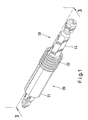
Fig. 1 is a perspective view of a not claimed tool holding device and a bit received in the tool holding device. -
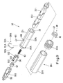
Fig. 2 is an exploded perspective view ofFig. 1 . -
Fig. 3 is a cross-sectional view taken along line 3-3 ofFig. 1 . -
Fig. 4 is a cross-sectional view taken along line 4-4 ofFig. 3 . -
Fig. 5 is a side view illustrating the tool holding device inFig. 1 connected to a power tool, with the power tool shown in phantom. The tool holding device is inserted in a hole and the bit is adapted to drive a fastener located within the hole, with the fastener shown in phantom. -
Fig. 6 is a cross-sectional view illustrating a sleeve of the tool holding device inFig. 1 operated to allow removal of the bit from the tool holding device. -
Fig. 7A is a cross-sectional view of the tool holding device inFig. 1 . -
Fig. 7B is a partial, enlarged view ofFig. 7A . -
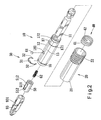
Fig. 8 is a perspective view of another not claimed tool holding device and a bit received in the tool holding device. -
Fig. 9 is an exploded perspective view ofFig. 8 . -
Fig. 10 is a cross-sectional view taken along line 10-10 ofFig. 8 . -
Fig. 11 is a cross-sectional view taken along line 11-11 ofFig. 10 . -
Fig. 12 is a cross-sectional view illustrating a sleeve of the tool holding device inFig. 8 operated to allow removal of the bit from the tool holding device. -
Fig. 13A is a cross-sectional view of the tool holding device inFig. 8 . -
Fig. 13B is a partial, enlarged view ofFig. 13A . -
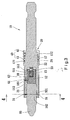
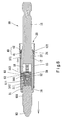
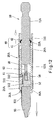
Fig. 14 is a cross-sectional view of a further not claimed tool holding device and a bit received in the tool holding device. -
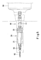
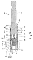
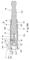
Fig. 15 is a cross-sectional view of' a tool holding device in accordance with a first embodiment of the present invention and a bit received in the tool holding device. -
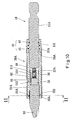
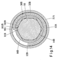
Fig. 16 is a cross-sectional view of a tool holding device in accordance with a second embodiment of the present invention and a bit received in the tool holding device. -
Fig. 17 is a cross-sectional view of a tool holding device in accordance with a third embodiment of the present invention and a bit received in the tool holding device. -
Figs. 1 though 7 show a not claimed tool bit holding device. The tool bit holding device includes atoolholder 10 having ashank 11 and asocket 12 integrally formed therewith. Theshank 11 includes a connecting end at a first end of thetoolholder 10 adapted to connect to apower tool 90, as shown inFig. 5 . Thesocket 12 includes acavity 14 at a second end of thetoolholder 10 adapted to receive abit 93. Thecavity 14, preferably includes six faces encompassing a boundary wall, and with each two of the six faces defining an included angle of substantially equaling to 120° at a corner, extends in thesocket 12 and defines an effective length L which is a longitudinal length measured for the boundary wall of thecavity 14 which is adapted to abut a peripheral wall of thebit 93. - The
socket 12 also includes anannular wall 15 having afirst slot 16 and asecond slot 161 cut into a region of the annular wall, and anaperture 162 defined in thesecond slot 161 and communicating with thecavity 14. Additionally, theaperture 162 is disposed about one of the corners. - A
hollow sleeve 20 is disposed circumferentially outside thetoolholder 10. Thesleeve 20 is axially and rotationally moveable in relation to thetoolholder 10, and is operable to move between a first position which allows for removal of thebit 93 and a second position which allows thebit 93 to be securely retained in thecavity 14 of thetoolholder 10. Thesleeve 20 includes an inner peripheral edge which circumferentially abuts theannular wall 15 of thesocket 12 and an outer peripheral edge. Thesleeve 20 defines afirst section 21 and asecond section 22 extending from an end of thefirst section 21. Thefirst section 21 includes a circular cross section and has an uniform internal diameter and an uniform external diameter with respect to a center of thecavity 14. In this case, the boundary wall of thecavity 14 defines a plurality of corners, i.e. six, and the center of thecavity 14 is a point where the six corners are equally spaced therefrom. The internal diameter is measured from the inner peripheral edge of thesleeve 20 to the center of thecavity 14. The external diameter is measured from the outer peripheral edge of thesleeve 20 to the center of thecavity 14. Moreover, the outer peripheral edge of thesecond section 22 is preferably ridged as to allow user to hold thesleeve 20 securely during operation thereof. - A returning
member 40 is disposed circumferentially between thetoolholder 10 and thesecond section 22 of thesleeve 20 for returning thesleeve 20 to a neutral position between the first and second positions. In this embodiment, the returningmember 40 is disposed on an engagingportion 17 defined on theannular wall 15 of thesocket 12. The engagingportion 17 includes a first shoulder and asecond shoulder second section 22 of thesleeve 20 includes aridge 24 extending from the inner peripheral edge thereof and toward the engagingportion 17. Theridge 24 is supported by thefirst shoulder 171. Additionally, the returningmember 40 includes afirst end 41 supported by theridge 24 and asecond end 42 supported by thesecond shoulder 172. - Optionally, the
first end 41 has a cross section greater than that of thesecond end 42. - Moreover, the
sleeve 20 of which does not surround the returningmember 40 abuts thetoolholder 10, and referring toFigs. 7A and7B , thefirst section 21 of thesleeve 20 includes a sleeve region corresponding at where the effective length L of thecavity 14 is measured including a thickness T21 measured from the inner peripheral edge to the outer peripheral edge thereof, while thesocket 12 includes a socket region corresponding at where the effective length L of thecavity 14 is measured including a minimum distance T12 equaling to a first length measured from the center of thecavity 14 to theannular wall 15 of thesocket 12 subtracted by a second distance measured from the center of thecavity 14 to one corner of thecavity 14, with T21 being less than T12. With this configuration, the tool holding device is adapted to be inserted into a narrow hole to drive afastener 92, as shown inFig. 5 . It is appreciated that the tool holding device therefore can be made with a smaller cross section than any those taught by the prior art. - A clipping
member 30, preferably made of metal, is mounted in the first andsecond slots portion 32 disposed about thefirst slot 16 and a retainingportion 31 received in thesecond slot 161, inserted in theaperture 162, and partially disposed in thecavity 14. The clippingmember 30 is selectively abutted by thefirst section 21 of thesleeve 20. Specifically, when thesleeve 20 is at the first position thefirst section 21 of thesleeve 20 does not abut the clippingmember 30, and when thesleeve 20 is at the second position thefirst section 21 of thesleeve 20 abuts the clippingmember 30. Note that when thesleeve 20 is at the first position, the retainingportion 31 of the clippingmember 30 can abut the receivedbit 93, particularly one of thecutouts 931 on thebit 93, in order that thebit 93 is prevented from falling out of the tool holding device due to gravity. Also, when thesleeve 20 is at the second position, the retainingportion 31 of the clippingmember 30 is restrained in movement by thefirst section 21 of thesleeve 20, thereby the tool holding device securely holds thebit 93. -
Fig. 4 shows that theannular wall 15 of thesocket 12 includes an arcuate area defining thefirst slot 16 and a flat area defining thesecond slot 161. Thefirst slot 16 is contiguous with thesecond slot 161. The clippingmember 30 includes two embracingportions 32 interconnected by the retainingportion 31. The two embracingportions 32 are arcuate and are received in thefirst slot 16. The retainingportion 31 has a bow-shaped edge which includes an arcuate side and a flat side received in thesecond slot 161. - In addition, the
socket 12 defines a center where theannular wall 15 is equally spaced from the center, and the clippingmember 30 defines an arc length having an angle with respect to center of thesocket 12 greater than 180°. - A
hole 18 extends longitudinally in thesocket 12 from an end of thecavity 14 and is in communication with thecavity 14. A throughhole 181 extends radially from theannular wall 15 of thesocket 12 to thehole 18 and is in communication with thehole 18. Apusher 50 is disposed in thehole 18 and includes a lateral side having a longitudinally extendedrecess 511 with two stoppingends 512 at a proximal end and a distal end thereof respectively. Adetent 61 is disposed in the throughhole 181 and is partially received by therecess 511. Aresilient member 62 is disposed in thehole 18 as to bias thepusher 50 in the hole. In this embodiment, thepusher 50 facilitates removal of thebit 93. -
Figs. 8 through 13 show another not claimed tool bit holding device. It is noted that like numerals are employed to denote like components of the previous not claimed tool bit holding device, however, bearing a letter. This not claimed tool bit holding device ofFigs. 8 through 13 differentiates from the not claimed tool bit holding device ofFigs. 1 through 7 in that ashank 11A is insertably installed in atunnel 13 defined in asocket 12A. Thetunnel 13 has a circular cross section and defines a diameter. Theshank 11 A defines a length measured from two diagonally opposed corners. The length is marginally smaller than the diameter so that theshank 11A is securely connected with thesocket 12A. Further, asleeve 20A includes afirst section 21 A and asecond section 22A releasably mounted to thefirst section 21 A. Further, the returningmember 40 is disposed on theshank 11A. Specifically, theshank 11A includes agroove 111, and thesecond section 22A of thesleeve 20A includes aridge 24A extending therefrom toward theshank 11A, and thefirst end 41 of the returningmember 40 is supported by theridge 24 while thesecond end 42 of the returningmember 40 is disposed in thegroove 111. Further, amagnet 52 is disposed at an end of thesocket 12A for attracting thebit 93. - Additionally, the
socket 12A includes acavity 14A and anannular wall 15A having an arcuate area defining afirst slot 16A. Asecond slot 161 A extends radially from thefirst slot 16A toward thecavity 14A, and anaperture 162A is defined in thesecond slot 161 and communicates with thecavity 14A. Further, a clippingmember 30A includes two embracingportions 32A interconnected by one retainingportion 31 A. The two embracingportions 32A are arcuate and are received in thefirst slot 16A. The retainingportion 31 A has a U-shaped edge and is received in thesecond slot 161A. - The
socket 12A also includes a center where theannular wall 15A is equally spaced from the center, and the clippingmember 30A defines an arc length having an angle with respect to center of thesocket 12A greater than 180°. -
Fig. 14 shows a further not claimed tool bit holding device. It is noted that like numerals are employed to denote like components of the not claimed tool bit holding device ofFigs. 1 through 7 , however, bearing a letter. This not claimed tool bit holding device ofFig. 14 differentiates from the not claimed tool bit holding devices ofFigs. 1 through 13 in that asocket 12B includes acavity 14B and anannular wall 15B having an arcuate area defining afirst slot 16B. Asecond slot 161B extends radially from thefirst slot 16B toward thecavity 14 and anaperture 162B is defined in thesecond slot 161B and communicates with thecavity 14B. Further, a clippingmember 30B includes an embracingportion 32B connected at an end of a retainingportion 31B. The embracingportion 32B is arcuate and is received in thefirst slot 16B. The retainingportion 31B has an inverted J-shaped edge received in thesecond slot 161B. - The
socket 12B also comprises a center where theannular wall 15B is equally spaced from the center, and the clippingmember 30B defines an arc length having an angle with respect to center of thesocket 12B greater than 180°. -
Fig. 15 shows a tool bit holding device in accordance with a first embodiment of the present invention. It is noted that like numerals are employed to denote like components of the not claimed tool bit holding device ofFigs. 1 through 7 , however, bearing a letter. This first embodiment differentiates from the not claimed tool bit holding devices ofFigs. 1 through 13 in that asocket 12C includes acavity 14C and anannular wall 15C having an arcuate area defining afirst slot 16C. Two opposingsecond slots 161C extend radially from the first slot toward thecavity 14C, and twoapertures 162C is defined in thesecond slots 161C and communicate with thecavities 14C respectively. Further, a clippingmember 30C includes two retainingportions 31C interconnected by an embracingportion 32C. Each of the two retainingportion 31C having an inverted J-shaped edge received in the twosecond slots 161C respectively. The embracingportion 32C is arcuate and is disposed about thefirst slot 16C. - The
socket 12C also includes a center where theannular wall 15C is equal spaced from the center, and the clippingmember 30C defines an arc length having an angle with respect to center of thesocket 12C substantially equaling to 180°. -
Fig. 16 shows a tool bit holding device in accordance with a second embodiment of the present invention. It is noted that like numerals are employed to denote like components of the not claimed tool bit holding device ofFigs. 1 through 7 , however, bearing a letter. This second embodiment differentiates from the not claimed tool bit holding devices ofFigs. 1 through 13 in that a socket 12D includes acavity 14D and anannular wall 15D having an arcuate area defining afirst slot 16D and a flat area defining thesecond slot 161D, and anaperture 162D is defined in thesecond slot 161D and communicates with thecavity 14D.. Thefirst slot 16D is contiguous with thesecond slot 161D. The clippingmember 30D includes a retainingportion 31D and an embracingportion 32D abutting the retainingportion 31D. The retainingportion 31D has a bow-shaped edge which includes an arcuate side and a flat side received in thesecond slot 161D. The embracingportion 32D is arcuate and is received in thefirst slot 16D. - The socket 12D also include a center where the
annular wall 15D is equal spaced from the center, and the embracingportion 32D defines an arc length having an angle with respect to center of the socket 12D greater than 180°. -
Fig. 17 shows a tool bit holding device in accordance with a third embodiment of the present invention. It is noted that like numerals are employed to denote like components of the not claimed tool bit holding device ofFigs. 1 through 7 , however, bearing a letter. This third embodiment differentiates from the not claimed tool bit holding devices ofFigs. 1 through 13 in that asocket 12E includes acavity 14E and anannular wall 15E having two opposing arcuate areas and two opposing flat areas defining afirst slot 16E. Asecond slot 161E extends radially from thefirst slot 16E toward thecavity 14E, and anaperture 162E is defined in thesecond slot 161 and communicates with thecavity 14E. The clippingmember 30E includes a retainingportion 31E and an embracingportion 32E abutting the retainingportion 31 E.The retaining portion 31 E has a ball-shaped edge and is received in thesecond slot 161E. The embracingportion 32E has two first flat sides received in the flat areas of thefirst slot 16E respectively, and an arcuate side between the two flat sides, and two substantially second flat sides extending from an end of the two first flat sides respectively. - The
socket 12E also includes a center where theannular wall 15E is equally spaced from the center, and the embracingportion 32E defines an arc length having an angle with respect to center of thesocket 12E greater than 180°.
Claims (9)
- A tool holding device comprising:a toolholder (10) including a shank (11, 11A) and a socket (12C, 12D, 12E), the shank (11, 11A) having a connecting end defined at a first end of the toolholder (10) adapted to connect to a power tool, the socket (12C, 12D, 12E) having a cavity (14C, 14D, 14E) defined at a second end of the toolholder (10) adapted to receive a bit (93), the cavity (14C, 14D, 14E) extending in the socket (12C, 12D, 12E) and defining an effective length (L) which is a longitudinal length measured for a boundary wall of the cavity (14C, 14D, 14E) which is adapted to abut a peripheral wall of the bit (93), the socket (12C, 12D, 12E) further having an annular wall (15C, 15D, 15E), a first slot and a second slot (16C, 16D, 16E; 161C, 161D, 161E) cut into a region of the annular wall (15C, 15D, 15E), and an aperture (162C, 162D, 162E) defined in the second slot (161C, 161 D, 161 E) and communicating with the cavity (14C, 14D, 14E);a sleeve (20, 20A) being hollow and disposed circumferentially outside the toolholder (10), the sleeve (20, 20A) being axially and rotationally moveable in relation to the toolholder (10), the sleeve (20, 20A) being operable to move between a first position which allows for removal of the bit (93) and a second position which allows the bit (93) to be securely retained in the cavity (14C, 14D, 14E) of the toolholder (10), the sleeve (20, 20A) defining a first section (21, 21A) and a second section (22, 22A) extending from an end of the first section (21, 21A), the sleeve (20, 20A) further including a returning member (40) disposed circumferentially between the toolholder (10) and the second section (22, 22A) thereof for biasing the sleeve (20, 20A) to the second position, and with a portion of the sleeve (20, 20A) which does not surround the returning member (40) abutting the toolholder (10); anda clipping member (30C, 30D, 30E) mounted in the first and second slots (16C, 16D, 16E; 161C, 161D, 161E) and having an embracing portion (32C, 32D, 32E) disposed about the first slot (16C, 16D, 16E) and a retaining portion (31C, 31D, 31E) received in the second slot (161C, 161D, 161E), inserted in the aperture (162C, 162D, 162E) and partially disposed in the cavity (14C, 14D, 14E), the clipping member (30C, 30D, 30E) being selectively abutted by the first section (21, 21 A) of the sleeve (20, 20A), and wherein when the sleeve (20, 20A) is at the first position the first section (21, 21A) of the sleeve (20, 20A) does not abut the clipping member (30C, 30D, 30E), and wherein when the sleeve (20, 20A) is at the second position the first section (21, 21A) of the sleeve (20, 20A) abuts the clipping member (30C, 30D, 30E); wherein:the annular wall (15C) of the socket (12C) comprises an arcuate area defining the first slot (16C), and with the socket comprising two opposing second slots (161C) extending radially from the first slot (16C) toward the cavity (14C), and wherein the clipping member (30C) comprises two retaining portions (31C) interconnected by the embracing portion (32C), with each of the two retaining portion (31C) having an inverted J-shaped edge received in the two second slots (161C) and partially disposed in the cavity (14C) whereby the bit (93) is frictionally retained by the clipping member (30C) when the sleeve (20, 20A) is at the first position respectively, with the embracing portion (32C) being arcuate disposed about the first slot (16C), and wherein the socket (12C) comprises a center, with the annular wall equally spaced from the center, and wherein the clipping member (30C) defines an arc length having an angle with respect to center of the socket (12C) substantially equaling to 180°; orthe annular wall (15D) of the socket (12D) comprises an arcuate area defining the first slot (16D) and a flat area defining the second slot (161D), with the first slot (16D) contiguous with the second slot (161D), and wherein the retaining portion (31D) is abutted by the embracing portion (32D), with the retaining portion (31D) having a bow-shaped edge which includes an arcuate side and a flat side received in the second slot and partially disposed in the cavity (14D) whereby the bit (93) is frictionally retained by the clipping member (30D) when the sleeve (20, 20A) is at the first position, with the embracing portion (32D) being arcuate and received in the first slot (16D), and wherein the socket (12D) comprises a center, with the annular wall equally spaced from the center, and wherein the embracing portion (32D) defines an arc length having an angle with respect to center of the socket (12D) greater than substantially equaling to 180°; orthe annular wall (15E) of the socket (12E) comprises two opposing arcuate areas and two opposing flat areas defining the first slot (16E), and with the second slot (161E) extending radially from the first slot toward the cavity (14E), and wherein the retaining portion (31E) is abutted by the embracing portion (32E), with the retaining portion (31E) having a ball-shaped edge received in the second slot (161 E) and partially disposed in the cavity (14E) whereby the bit (93) is frictionally retained by the clipping member (30E) when the sleeve (20, 20A) is at the first position, with the embracing portion (32E) having two first flat sides received in the flat areas of the first slot (16E) respectively, and an arcuate side between the two flat sides, and two substantially second flat sides extending from an end of the two first flat sides respectively, and wherein the socket (12E) comprises a center, with the annular wall (15E) equally spaced from the center, and wherein the embracing portion (32E) defines an arc length having an angle with respect to center of the socket (12E) greater than to 180°.
- The tool holding device as claimed in claim 1, wherein the sleeve (20, 20A) comprises an inner peripheral edge which circumferentially abuts the annular wall (15C, 15D, 15E) of the socket (12C, 12D, 12E) and an outer peripheral edge, and wherein the first section (21, 21A) of the sleeve (20, 20A) comprises a sleeve region corresponding at where the effective length (L) of the cavity (14C, 14D, 14E) is measured including a thickness (T21) measured from the inner peripheral edge to the outer peripheral edge thereof, and wherein the boundary wall of the cavity (14C, 14D, 14E) defines a plurality of corners and a center equal distanced with respect to the plurality of corners, and wherein the socket (12C, 12D, 12E) comprises a socket region corresponding at where the effective length (L) of the cavity (14C, 14D, 14E) is measured including a minimum distance (T12) equaling to a first length measured from the center of the cavity to the annular wall of the socket (12C, 12D, 12E) subtracted by a second distance measured from the center of the cavity (14C, 14D, 14E) to one of the plurality of corners of the cavity (14C, 14D, 14E), and wherein the thickness of the sleeve (20, 20A) is less than the minimum distance (T12).
- The tool holding device as claimed in claim 2, wherein the first section (21, 21A) of the sleeve (20, 20A) comprises a circular cross section and has an uniform internal diameter and an uniform external diameter with respect to the center of the cavity (14C, 14D, 14E), with the internal diameter measured from the inner peripheral edge of the sleeve (20, 20A) to the center of the cavity (14C, 14D, 14E), and with the external diameter measured from the outer peripheral edge of the sleeve (20, 20A) to the center of the cavity (14C, 14D, 14E).
- The tool holding device as claimed in claim 1, wherein the socket (12C, 12D, 12E) comprises a hole (18) extending longitudinally therein from an end of the cavity (14C, 14D, 14E) and communicating with the cavity (14C, 14D, 14E), and wherein the socket (12C, 12D, 12E) further comprises a through hole (181) extending radially from the annular wall (15C, 15D, 15E) of the socket (12C, 12D, 12E) to the hole (18) and communicating with the hole (18), and wherein the hole (18) includes a pusher (50) disposed therein, and wherein the pusher (50) comprises a lateral side having a longitudinally extended recess (511) with two stopping ends (512) at a proximal end and a distal end thereof respectively, and wherein the pusher (50) includes a detent (61) disposed in the through hole (181) and partially received by the recess (511) and a resilient member (62) disposed in the hole (18) as to bias the pusher (50) in the hole (18).
- The tool holding device as claimed in claim 4, wherein the pusher (50) comprises a magnet (52) mounted at an end thereof for attracting the bit (93).
- The tool holding device as claimed in claim 1, wherein the returning member (40) is disposed on an engaging portion (17) defined on the annular wall (15C, 15D, 15E) of the socket (12C, 12D, 12E), and wherein the engaging portion (17) comprises a first shoulder and a second shoulder (171, 172) at a proximal end and a distal end thereof respectively, and wherein the second section (22) of the sleeve (20) comprises a ridge (24) extending therefrom toward the engaging portion (17), and with the ridge (24) being supported by the first shoulder (171), and wherein the returning member (40) comprises a first end (41) supported by the ridge (24) and a second end (42) supported by the second shoulder (172).
- The tool holding device as claimed in claim 1, wherein the returning member (40) is disposed on the shank (11A), and wherein the shank (11A) comprises a non-circular peripheral wall, and a groove (111) cut circumferentially into the peripheral wall, and wherein the second section (22A) of the sleeve (20A) comprises a ridge (24A) extending therefrom toward the peripheral wall of the shank (11A), and wherein the returning member (40) comprises a first end (41) supported by the ridge (24A) and a second end (42) disposed in the groove (111).
- The tool holding device as claimed in claim 1, wherein the shank (11A) comprises a hexagonal cross section, and wherein the shank (11A) is insertably installed in a tunnel (13) defined in the socket (12C, 12D, 12E), with the tunnel (13) having a circular cross section, and wherein the tunnel (13) in the socket (12C, 12D, 12E) defines a diameter and the shank (11A) defines a length measured from two diagonally opposed corners marginally smaller than the diameter so that the shank (11A) is securely connected with the socket (12C, 12D, 12E).
- The tool holding device as claimed in claim 1, wherein the cavity (14C, 14D, 14E) comprises six faces encompassing the boundary wall, with the boundary wall defining six corners, with each two of the six faces defining an included angle of substantially equaling to 120°, and wherein the aperture (162C, 162D, 162E) is disposed about one of the corners.
Applications Claiming Priority (2)
| Application Number | Priority Date | Filing Date | Title |
|---|---|---|---|
| TW097129954A TW201006625A (en) | 2008-08-06 | 2008-08-06 | Tool chuck for screwdriver |
| EP09150026A EP2151304B1 (en) | 2008-08-06 | 2009-01-05 | Tool holding device |
Related Parent Applications (2)
| Application Number | Title | Priority Date | Filing Date |
|---|---|---|---|
| EP09150026.4 Division | 2009-01-05 | ||
| EP09150026A Division EP2151304B1 (en) | 2008-08-06 | 2009-01-05 | Tool holding device |
Publications (3)
| Publication Number | Publication Date |
|---|---|
| EP2517836A2 EP2517836A2 (en) | 2012-10-31 |
| EP2517836A3 EP2517836A3 (en) | 2013-01-09 |
| EP2517836B1 true EP2517836B1 (en) | 2014-05-14 |
Family
ID=41335245
Family Applications (2)
| Application Number | Title | Priority Date | Filing Date |
|---|---|---|---|
| EP09150026A Active EP2151304B1 (en) | 2008-08-06 | 2009-01-05 | Tool holding device |
| EP12177098.6A Active EP2517836B1 (en) | 2008-08-06 | 2009-01-05 | Tool holding device |
Family Applications Before (1)
| Application Number | Title | Priority Date | Filing Date |
|---|---|---|---|
| EP09150026A Active EP2151304B1 (en) | 2008-08-06 | 2009-01-05 | Tool holding device |
Country Status (4)
| Country | Link |
|---|---|
| US (1) | US7913592B2 (en) |
| EP (2) | EP2151304B1 (en) |
| JP (1) | JP3148573U (en) |
| TW (1) | TW201006625A (en) |
Families Citing this family (32)
| Publication number | Priority date | Publication date | Assignee | Title |
|---|---|---|---|---|
| DE102006016804A1 (en) * | 2006-04-10 | 2007-10-11 | Robert Bosch Gmbh | Tool holder for a hammer drill |
| JP5073321B2 (en) * | 2007-03-07 | 2012-11-14 | 株式会社マキタ | Bit setting device for rotary tools |
| US8196935B2 (en) * | 2008-03-03 | 2012-06-12 | Torque-Tech Precision Co., Ltd. | Safe and quick release device for a tool adapter |
| TW200950938A (en) * | 2008-06-11 | 2009-12-16 | Hou-Fei Hu | Chuck for bit |
| TW200950934A (en) * | 2008-06-11 | 2009-12-16 | Hou-Fei Hu | Chuck for bit |
| TWM353072U (en) * | 2008-09-03 | 2009-03-21 | Ho-Yi Chen | Tool extension bar capable of changing connection type |
| US8381830B2 (en) | 2009-05-05 | 2013-02-26 | Black & Decker Inc. | Power tool with integrated bit retention device |
| US8622401B2 (en) * | 2009-02-27 | 2014-01-07 | Black & Decker Inc. | Bit retention device |
| US8800999B2 (en) | 2009-02-27 | 2014-08-12 | Black & Decker Inc. | Bit retention device |
| TW201219163A (en) * | 2010-11-03 | 2012-05-16 | Hou-Fei Hu | comprising a slide channel in which a magnetic attraction device is received and movable between first and second positions to selectively contact the bit |
| US9079286B1 (en) * | 2011-12-15 | 2015-07-14 | Christian DeCamillis | Pneumatic actuator for impact engraving tool |
| US9505108B2 (en) | 2012-02-15 | 2016-11-29 | Black & Decker Inc. | Bit holder with floating magnet sleeve |
| US10150205B2 (en) | 2012-02-15 | 2018-12-11 | Black & Decker Inc. | Fastening tools with floating magnet sleeves |
| US9156147B2 (en) | 2012-02-15 | 2015-10-13 | Black & Decker Inc. | Quick change bit holder with ring magnet |
| US9943946B2 (en) | 2012-02-15 | 2018-04-17 | Black & Decker Inc. | Tool bits with floating magnet sleeves |
| US9227309B2 (en) | 2012-02-15 | 2016-01-05 | Black & Decker Inc. | Quick change bit holder with ring magnet |
| US20150075333A1 (en) * | 2013-09-19 | 2015-03-19 | Wei-Lin Chen | Wrench tool for screwdriver bits |
| USD736053S1 (en) * | 2013-09-27 | 2015-08-11 | Chervon (Hk) Limited | Bit |
| TWI522213B (en) * | 2014-01-22 | 2016-02-21 | Good Year Hardware Co Ltd | Tool head with limit block |
| KR101434174B1 (en) * | 2014-04-21 | 2014-08-26 | 주식회사 아임삭 | Rotating socket of electric tool |
| EP2937181A1 (en) * | 2014-04-22 | 2015-10-28 | HILTI Aktiengesellschaft | Tool holder |
| TWI542447B (en) * | 2014-08-27 | 2016-07-21 | Hou-Fei Hu | Ratchet wrench and its combination with the drive |
| TWI501841B (en) * | 2014-10-17 | 2015-10-01 | Chung Taan Ind Co Ltd | Connector |
| CN106032003B (en) * | 2015-03-17 | 2018-02-23 | 南京德朔实业有限公司 | Suitable for the combination of the extension bar component and screwdriver bit and extension bar component of screwdriver bit |
| US10513017B2 (en) | 2015-07-29 | 2019-12-24 | Black & Decker Inc. | Drive guide for fastening bits |
| USD789761S1 (en) | 2015-11-02 | 2017-06-20 | Black & Decker Inc. | Torsion bit |
| US10343266B2 (en) | 2015-12-10 | 2019-07-09 | Milwaukee Electric Tool Corporation | Bit holder assembly |
| WO2019074871A1 (en) | 2017-10-10 | 2019-04-18 | Milwaukee Electric Tool Corporation | Power tool to tool bit extension adapter |
| USD922166S1 (en) | 2018-10-09 | 2021-06-15 | Milwaukee Electric Tool Corporation | Tool bit adapter |
| TWI708661B (en) * | 2019-07-31 | 2020-11-01 | 嚴振宏 | Operating device for rotating element |
| US11426846B2 (en) * | 2020-04-09 | 2022-08-30 | Ningbo Hony Plastic Technology Co., Ltd | Quick-release screwdriver structure |
| US11925967B2 (en) * | 2021-11-15 | 2024-03-12 | Jake Matthew Thomas | Tool kit with quick-connect coupling for paintless dent removal |
Family Cites Families (15)
| Publication number | Priority date | Publication date | Assignee | Title |
|---|---|---|---|---|
| AU8020098A (en) | 1997-06-02 | 1998-12-21 | Wera Werk Hermann Werner Gmbh & Co. | Clamping chuck for bits or the like |
| US5934384A (en) * | 1998-04-27 | 1999-08-10 | Wang; Peter | Transmission shaft and bit mounting arrangement of a motor-driven hand drill |
| US6481315B1 (en) * | 2001-12-17 | 2002-11-19 | Sung-Hsiao Chang | Box and ratchet wheel arrangement for wrench |
| US6644150B2 (en) * | 2002-01-25 | 2003-11-11 | Tsai-Ching Chen | Tool bit holding device with an improved retaining effect |
| US6637755B2 (en) | 2002-03-22 | 2003-10-28 | Tsai-Ching Chen | Chuck device for miniature tool bits |
| US6860489B2 (en) * | 2003-03-31 | 2005-03-01 | Tsai-Ching Chen | Chuck device |
| US6840143B1 (en) * | 2003-06-20 | 2005-01-11 | Ying-Mo Lin | Adapter for screwdriver having elastic retainer ring |
| US6973858B2 (en) * | 2003-08-29 | 2005-12-13 | Jung-Chih Huang | Socket assembly that can be mounted and detached quickly |
| DE20318218U1 (en) * | 2003-11-25 | 2004-02-19 | Lin, Peng-Ho, Taiping | Tool head mounting, uses curved locking part in place of ball to fix tool head inside bushing |
| US20070044596A1 (en) * | 2005-08-23 | 2007-03-01 | Chang-Ying Chen | Bit connector |
| US20070234856A1 (en) * | 2006-04-05 | 2007-10-11 | Kuo-Chen Liu | Magnetic connecting tube for a screwdriver head |
| US7448302B2 (en) * | 2007-02-08 | 2008-11-11 | Daniel Huang | Adapter coupling device |
| DE202007004324U1 (en) * | 2007-03-23 | 2007-07-19 | Savco Corp., Dali City | Adapter coupling device |
| US20090139379A1 (en) * | 2007-11-30 | 2009-06-04 | Hsin Ying Enterprise Co., Ltd. | Driver tool for driving various tool members |
| TW200950934A (en) * | 2008-06-11 | 2009-12-16 | Hou-Fei Hu | Chuck for bit |
-
2008
- 2008-08-06 TW TW097129954A patent/TW201006625A/en unknown
- 2008-12-08 JP JP2008008571U patent/JP3148573U/en not_active Expired - Lifetime
- 2008-12-10 US US12/331,544 patent/US7913592B2/en active Active
-
2009
- 2009-01-05 EP EP09150026A patent/EP2151304B1/en active Active
- 2009-01-05 EP EP12177098.6A patent/EP2517836B1/en active Active
Also Published As
| Publication number | Publication date |
|---|---|
| EP2151304B1 (en) | 2013-03-20 |
| TW201006625A (en) | 2010-02-16 |
| EP2517836A2 (en) | 2012-10-31 |
| JP3148573U (en) | 2009-02-19 |
| EP2151304A2 (en) | 2010-02-10 |
| US20100031787A1 (en) | 2010-02-11 |
| US7913592B2 (en) | 2011-03-29 |
| TWI332891B (en) | 2010-11-11 |
| EP2517836A3 (en) | 2013-01-09 |
| EP2151304A3 (en) | 2011-03-02 |
Similar Documents
| Publication | Publication Date | Title |
|---|---|---|
| EP2517836B1 (en) | Tool holding device | |
| US8550471B2 (en) | Tool bit holder | |
| US6029549A (en) | Screwdriver with multi-position shank | |
| US7261023B2 (en) | Bit holder device | |
| EP2133175B1 (en) | Chuck for a bit | |
| US4787278A (en) | Tool bit driver with spring retainer | |
| US5916341A (en) | Combination screwdriver tool | |
| EP2133174B1 (en) | Chuck for bit | |
| CA2437568C (en) | Irregular-shank tools and drivers therefor | |
| US9406423B1 (en) | Magnetic sleeve assembly | |
| CA2567188A1 (en) | Universal tool bit shank | |
| EP3238867A1 (en) | Tap holder for multiple tap sizes | |
| US20080295653A1 (en) | Hand tool with bit release device | |
| EP3115155A1 (en) | Bit holder and combination of tool bit and bit holder | |
| GB2598019A (en) | Ratcheting handle for medical instrument | |
| US9032847B2 (en) | Multi-bit power driver | |
| US20090031867A1 (en) | Multi-function screwdriver | |
| US4934717A (en) | Quick exchange tool holder device | |
| US20150020652A1 (en) | Tool Bit Having Improved Removability | |
| CA2573827C (en) | Socket wrench/adaptor combination | |
| US20020141841A1 (en) | Tool bit | |
| US20030029283A1 (en) | Multiple screwdriver | |
| US3013594A (en) | Multiple screwdriver | |
| CN220446333U (en) | Tap and die handle assembly | |
| US20090243177A1 (en) | Locating pin and extraction tool |
Legal Events
| Date | Code | Title | Description |
|---|---|---|---|
| PUAI | Public reference made under article 153(3) epc to a published international application that has entered the european phase |
Free format text: ORIGINAL CODE: 0009012 |
|
| AC | Divisional application: reference to earlier application |
Ref document number: 2151304 Country of ref document: EP Kind code of ref document: P |
|
| AK | Designated contracting states |
Kind code of ref document: A2 Designated state(s): DE ES GB IT SE |
|
| PUAL | Search report despatched |
Free format text: ORIGINAL CODE: 0009013 |
|
| AK | Designated contracting states |
Kind code of ref document: A3 Designated state(s): DE ES GB IT SE |
|
| RIC1 | Information provided on ipc code assigned before grant |
Ipc: B25B 23/12 20060101ALI20121130BHEP Ipc: B25B 23/00 20060101AFI20121130BHEP Ipc: B25B 13/48 20060101ALI20121130BHEP |
|
| 17P | Request for examination filed |
Effective date: 20130109 |
|
| 17Q | First examination report despatched |
Effective date: 20130328 |
|
| GRAP | Despatch of communication of intention to grant a patent |
Free format text: ORIGINAL CODE: EPIDOSNIGR1 |
|
| INTG | Intention to grant announced |
Effective date: 20140109 |
|
| GRAS | Grant fee paid |
Free format text: ORIGINAL CODE: EPIDOSNIGR3 |
|
| GRAA | (expected) grant |
Free format text: ORIGINAL CODE: 0009210 |
|
| AC | Divisional application: reference to earlier application |
Ref document number: 2151304 Country of ref document: EP Kind code of ref document: P |
|
| AK | Designated contracting states |
Kind code of ref document: B1 Designated state(s): DE ES GB IT SE |
|
| REG | Reference to a national code |
Ref country code: GB Ref legal event code: FG4D |
|
| REG | Reference to a national code |
Ref country code: DE Ref legal event code: R096 Ref document number: 602009024193 Country of ref document: DE Effective date: 20140626 |
|
| REG | Reference to a national code |
Ref country code: SE Ref legal event code: TRGR |
|
| PG25 | Lapsed in a contracting state [announced via postgrant information from national office to epo] |
Ref country code: ES Free format text: LAPSE BECAUSE OF FAILURE TO SUBMIT A TRANSLATION OF THE DESCRIPTION OR TO PAY THE FEE WITHIN THE PRESCRIBED TIME-LIMIT Effective date: 20140514 |
|
| REG | Reference to a national code |
Ref country code: DE Ref legal event code: R097 Ref document number: 602009024193 Country of ref document: DE |
|
| PLBE | No opposition filed within time limit |
Free format text: ORIGINAL CODE: 0009261 |
|
| STAA | Information on the status of an ep patent application or granted ep patent |
Free format text: STATUS: NO OPPOSITION FILED WITHIN TIME LIMIT |
|
| 26N | No opposition filed |
Effective date: 20150217 |
|
| PG25 | Lapsed in a contracting state [announced via postgrant information from national office to epo] |
Ref country code: IT Free format text: LAPSE BECAUSE OF FAILURE TO SUBMIT A TRANSLATION OF THE DESCRIPTION OR TO PAY THE FEE WITHIN THE PRESCRIBED TIME-LIMIT Effective date: 20140514 |
|
| REG | Reference to a national code |
Ref country code: DE Ref legal event code: R097 Ref document number: 602009024193 Country of ref document: DE Effective date: 20150217 |
|
| GBPC | Gb: european patent ceased through non-payment of renewal fee |
Effective date: 20150105 |
|
| PG25 | Lapsed in a contracting state [announced via postgrant information from national office to epo] |
Ref country code: GB Free format text: LAPSE BECAUSE OF NON-PAYMENT OF DUE FEES Effective date: 20150105 |
|
| PGFP | Annual fee paid to national office [announced via postgrant information from national office to epo] |
Ref country code: DE Payment date: 20221207 Year of fee payment: 15 |
|
| PGFP | Annual fee paid to national office [announced via postgrant information from national office to epo] |
Ref country code: SE Payment date: 20231212 Year of fee payment: 16 |