EP2517820B1 - Method and auxiliary device for precision positioning of welded type nozzles - Google Patents
Method and auxiliary device for precision positioning of welded type nozzles Download PDFInfo
- Publication number
- EP2517820B1 EP2517820B1 EP12164650.9A EP12164650A EP2517820B1 EP 2517820 B1 EP2517820 B1 EP 2517820B1 EP 12164650 A EP12164650 A EP 12164650A EP 2517820 B1 EP2517820 B1 EP 2517820B1
- Authority
- EP
- European Patent Office
- Prior art keywords
- alignment
- positioning
- nozzle
- tip
- tips
- Prior art date
- Legal status (The legal status is an assumption and is not a legal conclusion. Google has not performed a legal analysis and makes no representation as to the accuracy of the status listed.)
- Not-in-force
Links
- 238000000034 method Methods 0.000 title claims description 38
- 238000003466 welding Methods 0.000 claims description 77
- 239000007921 spray Substances 0.000 claims description 30
- 238000012937 correction Methods 0.000 claims description 13
- 238000001816 cooling Methods 0.000 description 5
- 238000007796 conventional method Methods 0.000 description 4
- 229910000831 Steel Inorganic materials 0.000 description 2
- 238000005219 brazing Methods 0.000 description 2
- 238000004519 manufacturing process Methods 0.000 description 2
- 238000012986 modification Methods 0.000 description 2
- 230000004048 modification Effects 0.000 description 2
- 239000010959 steel Substances 0.000 description 2
- 230000002411 adverse Effects 0.000 description 1
- 238000004140 cleaning Methods 0.000 description 1
- 230000001419 dependent effect Effects 0.000 description 1
- 230000000694 effects Effects 0.000 description 1
- 238000009434 installation Methods 0.000 description 1
- 238000003754 machining Methods 0.000 description 1
Images









Classifications
-
- B—PERFORMING OPERATIONS; TRANSPORTING
- B23—MACHINE TOOLS; METAL-WORKING NOT OTHERWISE PROVIDED FOR
- B23K—SOLDERING OR UNSOLDERING; WELDING; CLADDING OR PLATING BY SOLDERING OR WELDING; CUTTING BY APPLYING HEAT LOCALLY, e.g. FLAME CUTTING; WORKING BY LASER BEAM
- B23K37/00—Auxiliary devices or processes, not specially adapted for a procedure covered by only one of the other main groups of this subclass
- B23K37/04—Auxiliary devices or processes, not specially adapted for a procedure covered by only one of the other main groups of this subclass for holding or positioning work
-
- B—PERFORMING OPERATIONS; TRANSPORTING
- B23—MACHINE TOOLS; METAL-WORKING NOT OTHERWISE PROVIDED FOR
- B23K—SOLDERING OR UNSOLDERING; WELDING; CLADDING OR PLATING BY SOLDERING OR WELDING; CUTTING BY APPLYING HEAT LOCALLY, e.g. FLAME CUTTING; WORKING BY LASER BEAM
- B23K37/00—Auxiliary devices or processes, not specially adapted for a procedure covered by only one of the other main groups of this subclass
- B23K37/04—Auxiliary devices or processes, not specially adapted for a procedure covered by only one of the other main groups of this subclass for holding or positioning work
- B23K37/0426—Fixtures for other work
-
- B—PERFORMING OPERATIONS; TRANSPORTING
- B23—MACHINE TOOLS; METAL-WORKING NOT OTHERWISE PROVIDED FOR
- B23K—SOLDERING OR UNSOLDERING; WELDING; CLADDING OR PLATING BY SOLDERING OR WELDING; CUTTING BY APPLYING HEAT LOCALLY, e.g. FLAME CUTTING; WORKING BY LASER BEAM
- B23K37/00—Auxiliary devices or processes, not specially adapted for a procedure covered by only one of the other main groups of this subclass
- B23K37/04—Auxiliary devices or processes, not specially adapted for a procedure covered by only one of the other main groups of this subclass for holding or positioning work
- B23K37/0417—Auxiliary devices or processes, not specially adapted for a procedure covered by only one of the other main groups of this subclass for holding or positioning work for spherical work
-
- B—PERFORMING OPERATIONS; TRANSPORTING
- B23—MACHINE TOOLS; METAL-WORKING NOT OTHERWISE PROVIDED FOR
- B23K—SOLDERING OR UNSOLDERING; WELDING; CLADDING OR PLATING BY SOLDERING OR WELDING; CUTTING BY APPLYING HEAT LOCALLY, e.g. FLAME CUTTING; WORKING BY LASER BEAM
- B23K37/00—Auxiliary devices or processes, not specially adapted for a procedure covered by only one of the other main groups of this subclass
- B23K37/04—Auxiliary devices or processes, not specially adapted for a procedure covered by only one of the other main groups of this subclass for holding or positioning work
- B23K37/053—Auxiliary devices or processes, not specially adapted for a procedure covered by only one of the other main groups of this subclass for holding or positioning work aligning cylindrical work; Clamping devices therefor
- B23K37/0536—Auxiliary devices or processes, not specially adapted for a procedure covered by only one of the other main groups of this subclass for holding or positioning work aligning cylindrical work; Clamping devices therefor for maintaining flanges on tubes
Definitions
- the present invention generally relates to a method for positioning an element during welding, and more particularly to a method for precision positioning of welded type nozzles during welding and to a method for connecting a plurality of welded type nozzles with a main pipe header.
- nozzles provide spray pattern in different shapes such as a sectorial, circular, elliptical, square or rectangular shape
- the angle, shape and size of the spray pattern depend on the geometric positions of the nozzles.
- each nozzle must be positioned at a proper and correct geometric position, in order to avoid interference between the spray patterns or adverse effect.
- a nozzle can generally be connected with a main pipe header by thread engagement or welding. Though relatively inexpensive to manufacture, threaded type nozzles are most often for low working pressure applications. Moreover, if a certain offset angle exists between adjacent nozzles, the installation and positioning process becomes difficult and time-consuming. Though relatively expensive, welded type nozzles can be conveniently and rapidly installed, removed or replaced. The correct positioned welded type nozzles are ensured always in the same spray configuration after nozzle replacement, and can be used in high working pressure applications, for example, common and important applications in hot-rolled steel strip plants, such as highpressure descaling, roll cooling, and steel strip surface cooling and cleaning.
- FIGS. 1-2 are schematic views illustrating prior art examples of performing a nozzle positioning during welding by using an alignment tip and an alignment plate;
- FIG. 3 is a schematic view of a conventional alignment tip.
- the alignment tip 11 has a groove 111 and a positioning structure 112 on an outer surface thereof.
- the positioning structure 112 may be a positioning flat surface (as shown in FIG. 3 ) or positioning key (as shown in FIG. 4 ); the positioning key may also be a dovetail key (for small size cooling nozzles), but is not limited thereto, and the alignment tip 11 has the same external dimension as a nozzle tip.
- a specific included angle exists between the groove 111 and the positioning structure 112, and the positioning structure 112 of the alignment tip 11 cooperates with a positioning structure (not shown in the drawings) located on an inner surface of a welding adapter 13, so that when a alignment plate 12 is used to correct the groove 111 of the alignment tip 11 to a parallel position, the positioning structures of all the welding adapters 13 are also rotated to the same specific angle accordingly.
- a distance between the alignment tip 11 and a center line 141 of the main pipe header 14 in a longitudinal direction is approximately equal to a length L 0 of an assembled nozzle after a nozzle tip is combined with the corresponding welding adapter 13, the length L 0 of the assembled nozzle is a distance between the nozzle tip and a center line 141 of a main pipe header 14 in a longitudinal direction, and the alignment tip 11 and the nozzle tip 15 have the same external dimension, so that a correction distance L of the conventional positioning device is equivalent to the length L 0 of the assembled nozzle, and a long-diameter center line 152 of a spray orifice 151 of the nozzle tip 15 forms a required offset angle ⁇ (as shown in FIG. 5 ) with the center line 141 of the main pipe header 14 in the longitudinal direction.
- ⁇ as shown in FIG. 5
- FIG. 6 is another schematic view of nozzle positioning by using an alignment plate during welding in the prior art
- FIG. 7 is a schematic cross-sectional view taken along a radial direction of a main pipe header shown in FIG. 6
- FIG. 8 is a top view of FIG. 6 after the alignment plate is removed.
- two processed positioning flat surfaces 211 are designed on an outer diameter of a welding adapter 21, and during welding, by using the two positioning flat surfaces 211 of each welding adapter 21 and a first alignment plate 22, the positioning flat surfaces 211 on two sides of each welding adapter 21 can be aligned, and top surfaces of all the welding adapters 21 are positioned at the same horizontal position by using a second alignment plate 23.
- the positioning flat surface 211 of the welding adapter 21 is parallel to or forms a certain included angle with a center line of a nozzle tip positioning slot inside the welding adapter 21, so that after the welding adapter 21 and a main pipe header 24 are welded, positioning at a required offset angle can be achieved.
- Such a conventional method is disadvantageous in that the machining thickness of the two positioning flat surfaces 211 needs to be taken into consideration, and accordingly, the wall thickness of the welding adapter 21 is thicker than ordinary ones. Therefore, such a conventional method is generally used for positioning of descaling nozzles, and seldom used for positioning of small size cooling nozzles.
- the above two conventional welded nozzle positioning methods facilitate positioning of the offset angle or length of the assembled nozzle, but cannot correct positioning for an error in nozzle pitch, an error in parallelism of nozzles or an angle error in lead angle between nozzles (included angle between a center line of the nozzle and a normal line of a working piece surface).
- the angle error in lead angle between nozzles is described below by way of example. Assuming that a predetermined lead angle is 15 ⁇ 1°, the lead angles of different nozzles can shift by 1° in different direction, and accordingly the angle error in lead angle between nozzles can reach 2°.
- the correction position of the conventional nozzle positioning method is located nearby the outlet of the nozzle tip.
- a position error in impact area of spray pattern on the working piece surface can be extended and amplified as the spray distance increases; as the spray distance may be several times the length of the nozzle after welding and assembly, the geometric error at the outlet of the nozzle can be amplified several times according to the spray distance, which is the greatest inevitable disadvantage of the conventional nozzle positioning method.
- US 2003/201302 A discloses an automated header brazing machine for determining the location of junction tubes along a header and automatically brazing them to the header and represents the closest prior art.
- US 2003/201302 A discloses an auxiliary device suitable for precision positioning of welded type nozzles, for cooperating with a plurality of welding adapters, wherein the welding adapters are used for being connected to a main pipe header and receiving a plurality of nozzle tips, the auxiliary device comprising: a plurality of alignment tips, wherein each alignment tip has a first end and a second end opposite to each other, each first end is away from the corresponding welding adapter and has a first positioning portion, and each second end is fixed to the corresponding welding adapter; and an alignment bar, having a plurality of second positioning portions, wherein structures of the second positioning portions cooperate with structures of the first positioning portions of the alignment tips, the alignment bar is combined with the alignment tips so that the first positioning portions of the alignment tips are aligned with the second positioning portions of the alignment bar, so as to precision position the nozzle
- US 5 098 006 A discloses an auxiliary device suitable for precision positioning of welded type nozzles similar to that disclosed by US 2003/201302 A . However, a correction distance in the sense of claim 1, after a nozzle tip is combined with the corresponding welding adapter, is not discloses.
- the present invention provides a method for precision positioning of welded type nozzles in a main pipe header, wherein each nozzle has a welding adapter and a nozzle tip, the method comprises the steps of: (a) combining a plurality of alignment tips with corresponding welding adapters, wherein each alignment tip has a first end and a second end opposite to each other, each first end is away from the corresponding welding adapter and has a first positioning portion, and each second end is fixed to the corresponding welding adapter; and (b) combining an alignment bar with the alignment tips, so that the first positioning portions of the alignment tips are aligned with a plurality of second positioning portions of the alignment bar, so as to precision position geometric positions of the nozzles, wherein structures of the second positioning portions cooperate with structures of the first positioning portions of the alignment tips, and after the alignment bar is combined with the alignment tips, a correction distance between an end surface of the alignment bar and a center line of the main pipe header in a longitudinal direction is larger than a length of an assembled nozzle after a nozzle tip
- the alignment tip and the alignment bar can be applied in cooperation during the process of welding the welding adapters of the nozzles and the main pipe header, so that errors in the geometric positions of the nozzles, for example, an error in nozzle pitch, an error in parallelism of nozzles and an angle error in included angle between the center line of the nozzle and the normal line of the working piece surface, can be accurately corrected.
- the correction position is close to the impact area of the spray pattern on the working piece surface, so that the extensible error generated by the conventional method can be reduced or avoided, thereby greatly improving the accuracy of the geometric position of the spray pattern of the nozzle.
- the auxiliary device 4 for precision positioning of welded type nozzles for use in a method according to the present invention is used for cooperating with a plurality of welding adapters 5, the welding adapters 5 are used for being connected to a main pipe header 6 and receiving a plurality of nozzle tips, a nozzle pitch E exists between adjacent nozzles to be positioned, and in this embodiment, the nozzle pitch E is a pitch between adjacent welding adapters 5.
- the auxiliary device 4 for precision positioning of welded type nozzles includes a plurality of alignment tips 41 and an alignment bar 42.
- Each alignment tip 41 has a first end 411 and a second end 412 opposite to each other, each first end 411 is away from the corresponding welding adapter 5 and has a first positioning portion 413, and each second end 412 is fixed to the corresponding welding adapter 5.
- the second end 412 of the alignment tip 41 has the same external dimension as the nozzle tip.
- the alignment bar 42 has a plurality of second positioning portions 423, and structures of the second positioning portions 423 cooperate with structures of first positioning portions 413 of the alignment tips 41.
- the first positioning portion 413 and the second positioning portion 423 may be a slot and key combination, for example, a combination of a slot with a slot, a combination of a slot with a key, or a combination of a key with a slot.
- the first positioning portions 413 have key slots 415
- the second positioning portions 423 have key slots 425 (as shown in FIGS. 9-12) ; or the first positioning portions 413 have keys, and the second positioning portions 423 have slots (as shown in FIGS. 13-15 ).
- each first positioning portion 413 has a circular shaft 414 and a key slot 415
- each second positioning portion 423 includes a circular hole 424 and key slots 425 on two sides of the circular hole 424, a fit tolerance of the circular hole 424 of each second positioning portion 423 preferably cooperates with an outer diameter of the circular shaft 414 of the corresponding alignment tip 41 (preferably, a proper clearance exists), and at least the width of the key slot 425 of each second positioning portion 423 cooperates with the width of the key slot 415 of each first positioning portion 413 (for example, the widths are the same).
- a positioning pitch identical to the nozzle pitch E exists between the second positioning portions 423.
- the alignment bar 42 is combined with the alignment tips 41, so that the circular shafts 414 and the key slots 415 of the first positioning portions 413 are aligned with the circular holes 424 and the key slots 425 of the second positioning portions 423.
- An outer shape of the second end 412 of each alignment tip 41 has a first positioning structure 417
- the first positioning structure 417 may be a positioning flat surface (as shown in FIG. 16 ) or positioning key (as shown in FIG. 17 )
- the positioning key may be a dovetail key (for small size cooling nozzles), but is not limited thereto, and the positioning key may be a positioning structure of any nozzle and welding adapter.
- the first positioning structures 417 of the alignment tips 41 cooperate with a second positioning structure (not shown in the drawings) on an inner surface of each welding adapter 5.
- the second end 412 of each alignment tip 41 is inserted into the corresponding welding adapter 5, and then locked to the corresponding welding adapter 5 by using a nut 8, so as to fix the alignment tips 41.
- first positioning structures 417 of the alignment tips 41 and the second positioning structure of each welding adapter 5 is described below by way of example.
- the first positioning structure 417 is parallel to a long-diameter center line 418 of the key slot 415 of the first positioning portion 413, and when the alignment bar 42 is used to adjust and position the alignment tip 41 so that the long-diameter center line 418 of the key slot 415 of the first positioning portion 413 is parallel to a center line 61 of the main pipe header 6 in a longitudinal direction (as shown in FIG. 18 ), the second positioning structure of each welding adapter 5 is also parallel to the center line 61 of the main pipe header 6 in the longitudinal direction.
- a set offset angle ⁇ (for example, 10° or 15°) exists between a positioning structure 91 of a used nozzle tip 9 and a long-diameter center line 93 of a spray orifice 92 of the nozzle tip 9, the nozzle has the offset angle ⁇ (as shown in FIG. 19 ) after the nozzle tip 9 is assembled to the welding adapter 5.
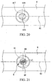
- an included angle can exist between the first positioning structure 417 and the long-diameter center line 418 of the key slot 415 of the first positioning portion 413, and when the alignment bar 42 is used to adjust and position the alignment tip 41 so that the long-diameter center line 418 of the key slot 415 of the first positioning portion 413 is parallel to the center line 61 of the main pipe header 6 in the longitudinal direction, an included angle exists between the second positioning structure of each welding adapter 5 and the center line 61 of the main pipe header 6 in the longitudinal direction (as shown in FIG. 20 ).
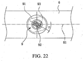
- the positioning structure 91 of the used nozzle tip 9 may be parallel to (as shown in FIG. 21 ) or form a presetting angle with (as shown in FIG.
- the offset angle ⁇ of the nozzle after the nozzle tip 9 is assembled to the welding adapter 5 can be defined.
- the included angle between the first positioning structure 417 and the long-diameter center line 418 of the key slot 415 of the first positioning portion 413 is 15°, and after the long-diameter center line 418 of the key slot 415 of the first positioning portion 413 is adjusted to be parallel to the center line 61 of the main pipe header 6 in the longitudinal direction, the second positioning structure of each welding adapter 5 also forms an included angle of 15° with the center line 61 of the main pipe header 6 in the longitudinal direction (anticlockwise). If the positioning structure 91 of the nozzle tip 9 is parallel to the long-diameter center line 93 of the spray orifice 92, the offset angle ⁇ of the nozzle is 15° (as shown in FIG.
- the offset angle ⁇ of the nozzle is -15° (clockwise) (as shown in FIG. 22 ) after the nozzle tip 9 is assembled to the welding adapter 5.
- a correction distance L between an end surface 426 of the alignment bar 42 and the center line 61 of the main pipe header 6 in the longitudinal direction is larger than a length L 0 of an assembled nozzle after a nozzle tip is combined with the corresponding welding adapter 5, and the length L 0 of the assembled nozzle is a distance between the nozzle tip and the center line 61 of the main pipe header 6 in the longitudinal direction.
- a spray distance between the nozzle and a working piece surface 7 is d, and a relation between L, L 0 and d is that:
- the alignment bar 42 is used to position two alignment tips 41 (for example, leftmost and rightmost alignment tips 41) or three alignment tips 41 (for example, leftmost, rightmost and intermediate alignment tips 41), where in this embodiment, first, the leftmost and rightmost alignment tips 41 are positioned, and then the circular hole 424 of the second positioning portion 423 is sleeved over the circular shaft 414 of the first positioning portion 413 of the corresponding alignment tip 41, and afterwards, the leftmost and rightmost alignment tips 41 are adjusted so that the key slots 415 of the first positioning portions 413 thereof are aligned with the key slots 425 of the corresponding second positioning portions 423, and at the same time the alignment bar 42 is adjusted so that an end surface 426 thereof is parallel to and aligned with end surfaces 416 of the first ends 411 of the two alignment tips 41.
- two alignment tips 41 for example, leftmost and rightmost alignment tips 41
- three alignment tips 41 for example, leftmost, rightmost and intermediate alignment tips 41
- the alignment bar 42 and the two alignment tips 41 can be fixed at side surfaces of the two alignment tips 41 by lateral screw fixation (but the present invention is not limited to this fixation manner), and then the geometric positions of the other alignment tips 41 are adjusted and aligned in the above manner according to the corresponding first positioning portions 413 and second positioning portions 423.
- the welding adapters 5 and the main pipe header 6 are connected by welding. It should be understood that the method for precision positioning of welded type nozzles of the present invention can correct a part of the alignment tips 41 or all of the alignment tips 41 at one time.
- the alignment bar 42 and the alignment tip 41 of the present invention are corrected at positions close to the working piece surface 7, so that the clearance between the first positioning portion 413 of the alignment tip 41 and the second positioning portion 423 of the alignment bar 42 is just a position error in impact area of spray pattern on the working piece surface 7, no extensible error that can be extended and amplified due to the spray distance exists, and therefore, almost no angle error exists.
- the clearance between the first positioning portion 413 of the alignment tip 41 and the second positioning portion 423 of the alignment bar 42 of the present invention and a maximum position error after assembly are 1 mm, and accordingly the maximum position error in spray area between adjacent nozzles after correction is also about 1 mm.
- the angle error needs to be taken into consideration in addition to the position and assembly errors.
- a position error in impact area of spray pattern can be extended and amplified as the spray distance increases, and as the spray distance may be several times the length of the nozzle after welding and assembly, the position error at the outlet of the nozzle can be amplified several times on the working piece surface. For example, if the clearance between the alignment tip and the alignment plate and a maximum position error after assembly are 1 mm, the error can be amplified several times as the spray distance extends.
- the method according to the present invention not only can greatly reduce the angle error in lead angle between nozzles, but also can greatly reduce the extensible position error in impact area of spray pattern.
- the offset angle of the nozzle can be corrected.
- an error in length of the assembled nozzle can be corrected.
- the difference between this embodiment and the first embodiment lies in that in this embodiment, the auxiliary device for precision positioning of welded type nozzles can further include an alignment plate 43. Parts that are the same as those in the first embodiment are denoted by the same reference numerals, and will not again be described in detail.
- the circular holes 424 of the alignment bar 42 are sleeved over the circular shafts 414 of the first ends 411 of two alignment tips 41 (or three alignment tips 41), and through the cooperation of the circular holes 424 and the circular shafts 414, an error in nozzle pitch E, an error in parallelism of nozzles and an angle error in included angle ⁇ between the center line of the nozzle and a normal line N of the working piece surface 7 are corrected.
- the end surface 426 of the alignment bar 42 is parallel to and aligned with the end surfaces 416 of the first ends 411 of the two alignment tips 41, thereby correcting error in length of the assembled nozzle.
- the alignment bar 42 and the at least two alignment tips 41 are fixed, and then the alignment plate 43 is disposed in the key slots 415 of the first ends 411 of the alignment tips 41, so that the key slots 415 of the first ends 411 of the alignment tips 41 are parallel to the alignment plate 43, thereby correcting the offset angle of the nozzle.
- the welding adapters 5 and the main pipe header 6 are connected by welding.
- the difference between this embodiment and the embodiment of FIGS. 9-12 lies in that in this embodiment, the first positioning portions 413 have slots 418, and the second positioning portions 423 have keys 427 and slots 428.
- the first positioning portions 413 have slots 418
- the second positioning portions 423 have keys 427 and slots 428.
- Parts that are the same as those in the embodiments of FIGS. 9-12 are denoted by the same reference numerals, and will not be described in further detail.
- the key 427 of the second positioning portion 423 of the alignment bar 42 is inserted into the slot 418 of the first positioning portion 413 of the alignment tip 41, and the slot 428 of the second positioning portion 423 of the alignment bar 42 is bilaterally sleeved into an outer edge of the alignment tip 41.
- the error in nozzle pitch E, the error in parallelism of nozzles, the angle error in included angle ⁇ between the center line of the nozzle and the normal line N of the working piece surface 7, and the error in length of the assembled nozzle can be corrected at the same time.
- FIG. 29 is a flowchart of a method for precision positioning of welded type nozzles according to the present invention.
- the auxiliary device 4 for precision positioning of welded type nozzles of the first embodiment shown in FIGS. 9-12 is described.
- Step S291 a plurality of alignment tips 41 are combined with each welding adapter 5, where each alignment tip 41 has a first end 411 and a second end 412 opposite to each other, each first end 411 is away from the corresponding welding adapter 5 and has a first positioning portion 413, and each second end 412 is fixed to the corresponding welding adapter 5.
- the second end 412 of the alignment tip 41 has the same external dimension as the nozzle tips of the nozzles to be positioned.
- the first positioning structure 417 the positioning flat surface as shown in FIG. 16 or the positioning key as shown in FIG. 17
- the alignment tips 41 are locked by using a nut 8.
- Step S292 an alignment bar 42 is combined with the alignment tips 41, so that the first positioning portions 413 of the alignment tips 41 are aligned with the second positioning portions 423 of the alignment bar 42, so as to position geometric positions of the nozzles.
- the alignment tip 41 and the alignment bar 42 can be applied in cooperation during the process of welding the welding adapters 5 of the nozzles and the main pipe header 6, so that the geometric positions of the nozzles, for example, an error in nozzle pitch E, an error in parallelism of nozzles and an angle error in included angle ⁇ between the center line of the nozzle and the normal line N of the working piece surface 7, can be accurately corrected.
- the correction position is close to the impact area of the spray pattern on the working piece surface 7, so that the extensible error generated by the conventional method can be reduced or avoided, thereby greatly improving the accuracy of the geometric position of the impact area of spray pattern.
Landscapes
- Physics & Mathematics (AREA)
- Optics & Photonics (AREA)
- Engineering & Computer Science (AREA)
- Mechanical Engineering (AREA)
- Butt Welding And Welding Of Specific Article (AREA)
- Nozzles (AREA)
Description
- The present invention generally relates to a method for positioning an element during welding, and more particularly to a method for precision positioning of welded type nozzles during welding and to a method for connecting a plurality of welded type nozzles with a main pipe header.
- Although different types of nozzles provide spray pattern in different shapes such as a sectorial, circular, elliptical, square or rectangular shape, the angle, shape and size of the spray pattern depend on the geometric positions of the nozzles. When a plurality of nozzles is arranged on the same header, each nozzle must be positioned at a proper and correct geometric position, in order to avoid interference between the spray patterns or adverse effect.
- A nozzle can generally be connected with a main pipe header by thread engagement or welding. Though relatively inexpensive to manufacture, threaded type nozzles are most often for low working pressure applications. Moreover, if a certain offset angle exists between adjacent nozzles, the installation and positioning process becomes difficult and time-consuming. Though relatively expensive, welded type nozzles can be conveniently and rapidly installed, removed or replaced. The correct positioned welded type nozzles are ensured always in the same spray configuration after nozzle replacement, and can be used in high working pressure applications, for example, common and important applications in hot-rolled steel strip plants, such as highpressure descaling, roll cooling, and steel strip surface cooling and cleaning.
-
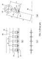
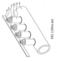
FIGS. 1-2 are schematic views illustrating prior art examples of performing a nozzle positioning during welding by using an alignment tip and an alignment plate;FIG. 3 is a schematic view of a conventional alignment tip. Referring toFIGS. 1-3 , thealignment tip 11 has agroove 111 and apositioning structure 112 on an outer surface thereof. Thepositioning structure 112 may be a positioning flat surface (as shown inFIG. 3 ) or positioning key (as shown inFIG. 4 ); the positioning key may also be a dovetail key (for small size cooling nozzles), but is not limited thereto, and thealignment tip 11 has the same external dimension as a nozzle tip. - A specific included angle exists between the
groove 111 and thepositioning structure 112, and thepositioning structure 112 of thealignment tip 11 cooperates with a positioning structure (not shown in the drawings) located on an inner surface of awelding adapter 13, so that when aalignment plate 12 is used to correct thegroove 111 of thealignment tip 11 to a parallel position, the positioning structures of all thewelding adapters 13 are also rotated to the same specific angle accordingly. - Referring to
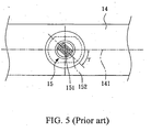
FIGS. 1-5 , since the external dimension of thealignment tip 11 are the same as thenozzle tip 15, after thewelding adapter 13 and themain pipe header 14 are welded and thenozzle tip 15 is mounted, a distance between thealignment tip 11 and acenter line 141 of themain pipe header 14 in a longitudinal direction is approximately equal to a length L0 of an assembled nozzle after a nozzle tip is combined with thecorresponding welding adapter 13, the length L0 of the assembled nozzle is a distance between the nozzle tip and acenter line 141 of amain pipe header 14 in a longitudinal direction, and thealignment tip 11 and thenozzle tip 15 have the same external dimension, so that a correction distance L of the conventional positioning device is equivalent to the length L0 of the assembled nozzle, and a long-diameter center line 152 of aspray orifice 151 of thenozzle tip 15 forms a required offset angle γ (as shown inFIG. 5 ) with thecenter line 141 of themain pipe header 14 in the longitudinal direction. Thealignment tip 11 can correct different offset angles according to different offset angle designs as required. -
FIG. 6 is another schematic view of nozzle positioning by using an alignment plate during welding in the prior art;FIG. 7 is a schematic cross-sectional view taken along a radial direction of a main pipe header shown inFIG. 6 ;FIG. 8 is a top view ofFIG. 6 after the alignment plate is removed. Referring toFIGS. 6-8 , in the conventional welding positioning method, two processed positioningflat surfaces 211 are designed on an outer diameter of awelding adapter 21, and during welding, by using the two positioningflat surfaces 211 of eachwelding adapter 21 and afirst alignment plate 22, the positioningflat surfaces 211 on two sides of eachwelding adapter 21 can be aligned, and top surfaces of all thewelding adapters 21 are positioned at the same horizontal position by using asecond alignment plate 23. The positioningflat surface 211 of thewelding adapter 21 is parallel to or forms a certain included angle with a center line of a nozzle tip positioning slot inside thewelding adapter 21, so that after thewelding adapter 21 and amain pipe header 24 are welded, positioning at a required offset angle can be achieved. - Such a conventional method is disadvantageous in that the machining thickness of the two positioning
flat surfaces 211 needs to be taken into consideration, and accordingly, the wall thickness of thewelding adapter 21 is thicker than ordinary ones. Therefore, such a conventional method is generally used for positioning of descaling nozzles, and seldom used for positioning of small size cooling nozzles. - The above two conventional welded nozzle positioning methods facilitate positioning of the offset angle or length of the assembled nozzle, but cannot correct positioning for an error in nozzle pitch, an error in parallelism of nozzles or an angle error in lead angle between nozzles (included angle between a center line of the nozzle and a normal line of a working piece surface).
- The angle error in lead angle between nozzles is described below by way of example. Assuming that a predetermined lead angle is 15±1°, the lead angles of different nozzles can shift by 1° in different direction, and accordingly the angle error in lead angle between nozzles can reach 2°.
- As the positioning accuracy of the conventional nozzle positioning method is insufficient, and due to manufacturing tolerance and assembly tolerance of the nozzle as well as deformation of the welding adapter after welding, there is an error in geometric position of the nozzle after welding and assembly. Such an error in geometric position can be extended and amplified as the spray distance of the nozzle increases (the larger the spray distance is, the larger the error in geometric position is). The correction position of the conventional nozzle positioning method is located nearby the outlet of the nozzle tip. A position error in impact area of spray pattern on the working piece surface can be extended and amplified as the spray distance increases; as the spray distance may be several times the length of the nozzle after welding and assembly, the geometric error at the outlet of the nozzle can be amplified several times according to the spray distance, which is the greatest inevitable disadvantage of the conventional nozzle positioning method.
-
US 2003/201302 A discloses an automated header brazing machine for determining the location of junction tubes along a header and automatically brazing them to the header and represents the closest prior art. Particularly,US 2003/201302 A discloses an auxiliary device suitable for precision positioning of welded type nozzles, for cooperating with a plurality of welding adapters, wherein the welding adapters are used for being connected to a main pipe header and receiving a plurality of nozzle tips, the auxiliary device comprising: a plurality of alignment tips, wherein each alignment tip has a first end and a second end opposite to each other, each first end is away from the corresponding welding adapter and has a first positioning portion, and each second end is fixed to the corresponding welding adapter; and an alignment bar, having a plurality of second positioning portions, wherein structures of the second positioning portions cooperate with structures of the first positioning portions of the alignment tips, the alignment bar is combined with the alignment tips so that the first positioning portions of the alignment tips are aligned with the second positioning portions of the alignment bar, so as to precision position the nozzles. However, a correction distance in the sense ofclaim 1, after a nozzle tip is combined with the corresponding welding adapter, is not discloses. -
US 5 098 006 A discloses an auxiliary device suitable for precision positioning of welded type nozzles similar to that disclosed byUS 2003/201302 A . However, a correction distance in the sense ofclaim 1, after a nozzle tip is combined with the corresponding welding adapter, is not discloses. - It is an object of the present invention to provide an enhanced method for precision positioning of welded type nozzles in a main pipe header in a convenient and more precise manner. It is a further object of the present invention to provide an enhanced method for connecting a plurality of welded type nozzles with a main pipe header using such an enhanced method for precision positioning of welded type nozzles.
- This object is solved by device method for precision positioning of welded type nozzles in a main pipe header according to
claim 1 and by a method for connecting a plurality of welded type nozzles with a main pipe header according toclaim 6. Further advantageous embodiments are the subject-matter of the dependent claims. - Thus the present invention provides a method for precision positioning of welded type nozzles in a main pipe header, wherein each nozzle has a welding adapter and a nozzle tip, the method comprises the steps of: (a) combining a plurality of alignment tips with corresponding welding adapters, wherein each alignment tip has a first end and a second end opposite to each other, each first end is away from the corresponding welding adapter and has a first positioning portion, and each second end is fixed to the corresponding welding adapter; and (b) combining an alignment bar with the alignment tips, so that the first positioning portions of the alignment tips are aligned with a plurality of second positioning portions of the alignment bar, so as to precision position geometric positions of the nozzles, wherein structures of the second positioning portions cooperate with structures of the first positioning portions of the alignment tips, and after the alignment bar is combined with the alignment tips, a correction distance between an end surface of the alignment bar and a center line of the main pipe header in a longitudinal direction is larger than a length of an assembled nozzle after a nozzle tip is combined with the corresponding welding adapter, and the length of the assembled nozzle is a distance between the nozzle tip and the center line of the main pipe header in the longitudinal direction.
- By using the method for precision positioning of welded type nozzles of the present invention, the alignment tip and the alignment bar can be applied in cooperation during the process of welding the welding adapters of the nozzles and the main pipe header, so that errors in the geometric positions of the nozzles, for example, an error in nozzle pitch, an error in parallelism of nozzles and an angle error in included angle between the center line of the nozzle and the normal line of the working piece surface, can be accurately corrected. In addition, the correction position is close to the impact area of the spray pattern on the working piece surface, so that the extensible error generated by the conventional method can be reduced or avoided, thereby greatly improving the accuracy of the geometric position of the spray pattern of the nozzle.
- Other features and advantages of the present invention will become more apparent from the detailed descriptions given below with reference to the accompanying drawings.
-
- FIGS. 1-2
- are schematic views illustrating prior art examples of performing a nozzle positioning during welding by using an alignment tip and an alignment plate;
- FIG. 3
- is a schematic view of a conventional alignment tip;
- FIG. 4
- is a schematic view of another conventional alignment tip;
- FIG. 5
- is a schematic view of a conventional nozzle after positioning;
- FIG. 6
- is another schematic view of nozzle positioning by using an alignment plate during welding in the prior art;
- FIG. 7
- is a schematic cross-sectional view taken along a radial direction of a main pipe header shown in
FIG. 6 ; - FIG. 8
- is a top view of
FIG. 6 after the alignment plate is removed; - FIG. 9
- is a schematic view of a first embodiment of nozzle positioning according to the present invention by using an auxiliary device for precision positioning of welded type nozzles;
- FIG. 10
- is a partially enlarged view of part G in
FIG. 9 ; - FIG. 11
- is an A-A view of
FIG. 9 ; - FIG. 12
- is a B-B view of
FIG. 9 ; - FIGS. 13-15
- are schematic views of performing a nozzle positioning while first and second positioning portions of an auxiliary device for precision positioning of welded type nozzles are a key and a slot, respectively;
- FIGS. 16-17
- are schematic views illustrating two different positioning structures of the alignment tip for use in a method for precision positioning according to the present invention;
- FIGS. 18-22
- are schematic views illustrating different correction manners of an offset angle of the nozzle according to the present invention;
- FIGS. 23-25
- are schematic views of performing the precision positioning of welded type nozzles according to the present invention by using an alignment bar and an alignment plate of the auxiliary device for precision positioning of welded type nozzle;
- FIG. 26
- is a schematic view of another embodiment of performing the nozzle positioning during welding according to the present invention by using the auxiliary device for precision positioning of welded type nozzles;
- FIG. 27
- is a partially enlarged view of part I in
FIG. 26 ; - FIG. 28
- is an E-E view of
FIG. 26 ; and - FIG. 29
- is a flowchart of a method for precision positioning of welded type nozzles according to the present invention.
- Referring to
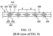
FIGS. 9-12 , theauxiliary device 4 for precision positioning of welded type nozzles for use in a method according to the present invention is used for cooperating with a plurality ofwelding adapters 5, thewelding adapters 5 are used for being connected to amain pipe header 6 and receiving a plurality of nozzle tips, a nozzle pitch E exists between adjacent nozzles to be positioned, and in this embodiment, the nozzle pitch E is a pitch betweenadjacent welding adapters 5. - The
auxiliary device 4 for precision positioning of welded type nozzles includes a plurality ofalignment tips 41 and analignment bar 42. Eachalignment tip 41 has afirst end 411 and asecond end 412 opposite to each other, eachfirst end 411 is away from thecorresponding welding adapter 5 and has afirst positioning portion 413, and eachsecond end 412 is fixed to thecorresponding welding adapter 5. Thesecond end 412 of thealignment tip 41 has the same external dimension as the nozzle tip. - The
alignment bar 42 has a plurality ofsecond positioning portions 423, and structures of thesecond positioning portions 423 cooperate with structures offirst positioning portions 413 of thealignment tips 41. Thefirst positioning portion 413 and thesecond positioning portion 423 may be a slot and key combination, for example, a combination of a slot with a slot, a combination of a slot with a key, or a combination of a key with a slot. For example, thefirst positioning portions 413 havekey slots 415, and thesecond positioning portions 423 have key slots 425 (as shown inFIGS. 9-12) ; or thefirst positioning portions 413 have keys, and thesecond positioning portions 423 have slots (as shown inFIGS. 13-15 ). - In this embodiment, each
first positioning portion 413 has acircular shaft 414 and akey slot 415, eachsecond positioning portion 423 includes acircular hole 424 andkey slots 425 on two sides of thecircular hole 424, a fit tolerance of thecircular hole 424 of eachsecond positioning portion 423 preferably cooperates with an outer diameter of thecircular shaft 414 of the corresponding alignment tip 41 (preferably, a proper clearance exists), and at least the width of thekey slot 425 of eachsecond positioning portion 423 cooperates with the width of thekey slot 415 of each first positioning portion 413 (for example, the widths are the same). - A positioning pitch identical to the nozzle pitch E exists between the
second positioning portions 423. Thealignment bar 42 is combined with thealignment tips 41, so that thecircular shafts 414 and thekey slots 415 of thefirst positioning portions 413 are aligned with thecircular holes 424 and thekey slots 425 of thesecond positioning portions 423. - An outer shape of the
second end 412 of eachalignment tip 41 has afirst positioning structure 417, thefirst positioning structure 417 may be a positioning flat surface (as shown inFIG. 16 ) or positioning key (as shown inFIG. 17 ), the positioning key may be a dovetail key (for small size cooling nozzles), but is not limited thereto, and the positioning key may be a positioning structure of any nozzle and welding adapter. Thefirst positioning structures 417 of thealignment tips 41 cooperate with a second positioning structure (not shown in the drawings) on an inner surface of eachwelding adapter 5. Thesecond end 412 of eachalignment tip 41 is inserted into thecorresponding welding adapter 5, and then locked to thecorresponding welding adapter 5 by using anut 8, so as to fix thealignment tips 41. - The cooperation between the
first positioning structures 417 of thealignment tips 41 and the second positioning structure of eachwelding adapter 5 is described below by way of example. - The
first positioning structure 417 is parallel to a long-diameter center line 418 of thekey slot 415 of thefirst positioning portion 413, and when thealignment bar 42 is used to adjust and position thealignment tip 41 so that the long-diameter center line 418 of thekey slot 415 of thefirst positioning portion 413 is parallel to acenter line 61 of themain pipe header 6 in a longitudinal direction (as shown inFIG. 18 ), the second positioning structure of eachwelding adapter 5 is also parallel to thecenter line 61 of themain pipe header 6 in the longitudinal direction. When a set offset angle γ (for example, 10° or 15°) exists between apositioning structure 91 of a usednozzle tip 9 and a long-diameter center line 93 of aspray orifice 92 of thenozzle tip 9, the nozzle has the offset angle γ (as shown inFIG. 19 ) after thenozzle tip 9 is assembled to thewelding adapter 5. - It should be understood that an included angle can exist between the
first positioning structure 417 and the long-diameter center line 418 of thekey slot 415 of thefirst positioning portion 413, and when thealignment bar 42 is used to adjust and position thealignment tip 41 so that the long-diameter center line 418 of thekey slot 415 of thefirst positioning portion 413 is parallel to thecenter line 61 of themain pipe header 6 in the longitudinal direction, an included angle exists between the second positioning structure of eachwelding adapter 5 and thecenter line 61 of themain pipe header 6 in the longitudinal direction (as shown inFIG. 20 ). Thepositioning structure 91 of the usednozzle tip 9 may be parallel to (as shown inFIG. 21 ) or form a presetting angle with (as shown inFIG. 22 ) the long-diameter center line 93 of thespray orifice 92, and through the cooperation of the included angle and the presetting angle, the offset angle γ of the nozzle after thenozzle tip 9 is assembled to thewelding adapter 5 can be defined. - For example, the included angle between the
first positioning structure 417 and the long-diameter center line 418 of thekey slot 415 of thefirst positioning portion 413 is 15°, and after the long-diameter center line 418 of thekey slot 415 of thefirst positioning portion 413 is adjusted to be parallel to thecenter line 61 of themain pipe header 6 in the longitudinal direction, the second positioning structure of eachwelding adapter 5 also forms an included angle of 15° with thecenter line 61 of themain pipe header 6 in the longitudinal direction (anticlockwise). If thepositioning structure 91 of thenozzle tip 9 is parallel to the long-diameter center line 93 of thespray orifice 92, the offset angle γ of the nozzle is 15° (as shown inFIG. 21 ) after thenozzle tip 9 is assembled to thewelding adapter 5; and if thepositioning structure 91 of thenozzle tip 9 forms a set angle of 30° (anticlockwise) with the long-diameter center line 93 of thespray orifice 92, the offset angle γ of the nozzle is -15° (clockwise) (as shown inFIG. 22 ) after thenozzle tip 9 is assembled to thewelding adapter 5. - After the
alignment bar 42 is combined with thealignment tips 41, a correction distance L between anend surface 426 of thealignment bar 42 and thecenter line 61 of themain pipe header 6 in the longitudinal direction is larger than a length L0 of an assembled nozzle after a nozzle tip is combined with thecorresponding welding adapter 5, and the length L0 of the assembled nozzle is a distance between the nozzle tip and thecenter line 61 of themain pipe header 6 in the longitudinal direction. A spray distance between the nozzle and a workingpiece surface 7 is d, and a relation between L, L0 and d is that: - when d≤200 mm, L0<L<L0+500 mm; and
- when d>200 mm, L0<L<L0+3d.
- The method for precision positioning of welded type nozzles of the present invention is described below by way of example, but the present invention is not limited thereto. First, the
alignment bar 42 is used to position two alignment tips 41 (for example, leftmost and rightmost alignment tips 41) or three alignment tips 41 (for example, leftmost, rightmost and intermediate alignment tips 41), where in this embodiment, first, the leftmost andrightmost alignment tips 41 are positioned, and then thecircular hole 424 of thesecond positioning portion 423 is sleeved over thecircular shaft 414 of thefirst positioning portion 413 of thecorresponding alignment tip 41, and afterwards, the leftmost andrightmost alignment tips 41 are adjusted so that thekey slots 415 of thefirst positioning portions 413 thereof are aligned with thekey slots 425 of the correspondingsecond positioning portions 423, and at the same time thealignment bar 42 is adjusted so that anend surface 426 thereof is parallel to and aligned withend surfaces 416 of the first ends 411 of the twoalignment tips 41. - Next, the
alignment bar 42 and the twoalignment tips 41 can be fixed at side surfaces of the twoalignment tips 41 by lateral screw fixation (but the present invention is not limited to this fixation manner), and then the geometric positions of theother alignment tips 41 are adjusted and aligned in the above manner according to the correspondingfirst positioning portions 413 andsecond positioning portions 423. After all thealignment tips 41 are corrected, thewelding adapters 5 and themain pipe header 6 are connected by welding. It should be understood that the method for precision positioning of welded type nozzles of the present invention can correct a part of thealignment tips 41 or all of thealignment tips 41 at one time. - The
alignment bar 42 and thealignment tip 41 of the present invention are corrected at positions close to the workingpiece surface 7, so that the clearance between thefirst positioning portion 413 of thealignment tip 41 and thesecond positioning portion 423 of thealignment bar 42 is just a position error in impact area of spray pattern on the workingpiece surface 7, no extensible error that can be extended and amplified due to the spray distance exists, and therefore, almost no angle error exists. For example, the clearance between thefirst positioning portion 413 of thealignment tip 41 and thesecond positioning portion 423 of thealignment bar 42 of the present invention and a maximum position error after assembly are 1 mm, and accordingly the maximum position error in spray area between adjacent nozzles after correction is also about 1 mm. - In contrast, in the conventional welded nozzle positioning method, as the correction position is located nearby the exit of the nozzle tip and is spaced from the working piece surface by a spray distance, the angle error needs to be taken into consideration in addition to the position and assembly errors. A position error in impact area of spray pattern can be extended and amplified as the spray distance increases, and as the spray distance may be several times the length of the nozzle after welding and assembly, the position error at the outlet of the nozzle can be amplified several times on the working piece surface. For example, if the clearance between the alignment tip and the alignment plate and a maximum position error after assembly are 1 mm, the error can be amplified several times as the spray distance extends.
- Compared with the conventional welded nozzle positioning method, the method according to the present invention not only can greatly reduce the angle error in lead angle between nozzles, but also can greatly reduce the extensible position error in impact area of spray pattern.
- In addition, through the cooperation of the
key slot 415 of thefirst positioning portion 413 and thekey slots 425 of the second positioning portion 423 (or through the cooperation of the key slot and the slot as shown inFIGS. 13-15 ), the offset angle of the nozzle can be corrected. Through the cooperation of theend surface 416 of thefirst end 411 of thealignment tip 41 and theend surface 426 of thealignment bar 42, an error in length of the assembled nozzle can be corrected. Thus, precision positioning of the nozzles can be achieved. - Referring to
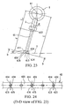
FIGS. 23-25 , the difference between this embodiment and the first embodiment lies in that in this embodiment, the auxiliary device for precision positioning of welded type nozzles can further include analignment plate 43. Parts that are the same as those in the first embodiment are denoted by the same reference numerals, and will not again be described in detail. - First, the
circular holes 424 of thealignment bar 42 are sleeved over thecircular shafts 414 of the first ends 411 of two alignment tips 41 (or three alignment tips 41), and through the cooperation of thecircular holes 424 and thecircular shafts 414, an error in nozzle pitch E, an error in parallelism of nozzles and an angle error in included angle β between the center line of the nozzle and a normal line N of the workingpiece surface 7 are corrected. Theend surface 426 of thealignment bar 42 is parallel to and aligned with the end surfaces 416 of the first ends 411 of the twoalignment tips 41, thereby correcting error in length of the assembled nozzle. - Next, the
alignment bar 42 and the at least twoalignment tips 41 are fixed, and then thealignment plate 43 is disposed in thekey slots 415 of the first ends 411 of thealignment tips 41, so that thekey slots 415 of the first ends 411 of thealignment tips 41 are parallel to thealignment plate 43, thereby correcting the offset angle of the nozzle. After all thealignment tips 41 are corrected, thewelding adapters 5 and themain pipe header 6 are connected by welding. - Referring to
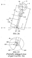
FIGS. 26-28 , the difference between this embodiment and the embodiment ofFIGS. 9-12 lies in that in this embodiment, thefirst positioning portions 413 haveslots 418, and thesecond positioning portions 423 havekeys 427 andslots 428. Parts that are the same as those in the embodiments ofFIGS. 9-12 are denoted by the same reference numerals, and will not be described in further detail. - The key 427 of the
second positioning portion 423 of thealignment bar 42 is inserted into theslot 418 of thefirst positioning portion 413 of thealignment tip 41, and theslot 428 of thesecond positioning portion 423 of thealignment bar 42 is bilaterally sleeved into an outer edge of thealignment tip 41. Through the cooperation of the key 427 and theslot 428 of thesecond positioning portion 423 with theslot 418 of thefirst positioning portion 413 and the outer edge of thealignment tip 41, the error in nozzle pitch E, the error in parallelism of nozzles, the angle error in included angle β between the center line of the nozzle and the normal line N of the workingpiece surface 7, and the error in length of the assembled nozzle can be corrected at the same time. -
FIG. 29 is a flowchart of a method for precision positioning of welded type nozzles according to the present invention. In this embodiment, theauxiliary device 4 for precision positioning of welded type nozzles of the first embodiment shown inFIGS. 9-12 is described. In Step S291, a plurality ofalignment tips 41 are combined with eachwelding adapter 5, where eachalignment tip 41 has afirst end 411 and asecond end 412 opposite to each other, eachfirst end 411 is away from thecorresponding welding adapter 5 and has afirst positioning portion 413, and eachsecond end 412 is fixed to thecorresponding welding adapter 5. - In this embodiment, the
second end 412 of thealignment tip 41 has the same external dimension as the nozzle tips of the nozzles to be positioned. After the first positioning structure 417 (the positioning flat surface as shown inFIG. 16 or the positioning key as shown inFIG. 17 ) of thesecond end 412 of eachalignment tip 41 is disposed in thecorresponding welding adapter 5 to cooperate with the second positioning structure on the inner surface of thewelding adapter 5, thealignment tips 41 are locked by using anut 8. - In Step S292, an
alignment bar 42 is combined with thealignment tips 41, so that thefirst positioning portions 413 of thealignment tips 41 are aligned with thesecond positioning portions 423 of thealignment bar 42, so as to position geometric positions of the nozzles. - For the mode of positioning the geometric positions of the nozzles (including the error in nozzle pitch E, the error in parallelism of nozzle, the angle error in included angle β between the center line of the nozzle and the normal line N of the working
piece surface 7, and the error in length of the assembled nozzle) by using thefirst positioning portions 413 of thealignment tips 41 and thesecond positioning portions 423 of thealignment bar 42, reference can be made to the description of the first embodiment of nozzle positioning by using the auxiliary device for precision positioning of welded type nozzles during welding, and the details will not be described herein again. - By using the method and
auxiliary device 4 for precision positioning of welded type nozzles according to the present invention, thealignment tip 41 and thealignment bar 42 can be applied in cooperation during the process of welding thewelding adapters 5 of the nozzles and themain pipe header 6, so that the geometric positions of the nozzles, for example, an error in nozzle pitch E, an error in parallelism of nozzles and an angle error in included angle β between the center line of the nozzle and the normal line N of the workingpiece surface 7, can be accurately corrected. In addition, the correction position is close to the impact area of the spray pattern on the workingpiece surface 7, so that the extensible error generated by the conventional method can be reduced or avoided, thereby greatly improving the accuracy of the geometric position of the impact area of spray pattern. - While several embodiments of the present invention have been illustrated and described, various modifications and improvements can be made by those skilled in the art. The embodiments of the present invention are therefore described in an illustrative but not in a restrictive sense. It is intended that the present invention should not be limited to the particular forms as illustrated and that all modifications which maintain the scope of the present invention are within the scope defined in the appended claims.
Claims (6)
- A method for precision positioning of welded type nozzles in a main pipe header (6), wherein each nozzle has a welding adapter (5) and a nozzle tip, the method comprising:(a) combining a plurality of alignment tips (41) with corresponding welding adapters (5), wherein each alignment tip (41) has a first end (411) and a second end (412) opposite to each other, each first end (411) is away from the corresponding welding adapter (5) and has a first positioning portion (413), and each second end (412) is fixed to the corresponding welding adapter (5); and(b) combining an alignment bar (42) with the alignment tips (41), so that the first positioning portions (413) of the alignment tips (41) are aligned with a plurality of second positioning portions (423) of the alignment bar (42), so as to precision position geometric positions of the nozzles, wherein structures of the second positioning portions (423) cooperate with structures of the first positioning portions (413) of the alignment tips (41), and after the alignment bar (42) is combined with the alignment tips (41), a correction distance (L) between an end surface (426) of the alignment bar (42) and a center line (61) of the main pipe header (6) in a longitudinal direction is larger than a length (L0) of an assembled nozzle after a nozzle tip is combined with the corresponding welding adapter (5), and the length (L0) of the assembled nozzle is a distance between the nozzle tip and the center line (61) of the main pipe header (6) in the longitudinal direction.
- The method according to claim 2, wherein in step (a), the second end (412) of the alignment tip (41) has the same external dimension as the nozzle tip.
- The method according to claim 1 or 2, wherein in step (b), the correction distance is L, the length of the assembled nozzle is L0, a spray distance between the nozzle and a working piece surface is d, and a relation between L, L0 and d is that:when d≤200 mm, L0<L<L0+500 mm; andwhen d>200 mm, L0<L<L0+3d.
- The method according to any of the preceding claims, wherein the first positioning portion (413) of the alignment tip (41) and the second positioning portion (423) of the alignment bar (42) are a slot and key combination.
- The method according to any of the preceding claims, further comprising:locking the plurality of alignment tips (41) by using nuts (8).
- A method for connecting a plurality of welded type nozzles with a main pipe header (6), wherein each nozzle has a welding adapter (5) and a nozzle tip, comprising:precision positioning the plurality of welded type nozzles in the main pipe header (6) using the method as claimed in any of the preceding claims; andconnecting the plurality of welded type nozzles with the main pipe header (6) using welding.
Applications Claiming Priority (1)
| Application Number | Priority Date | Filing Date | Title |
|---|---|---|---|
| TW100114767A TWI421135B (en) | 2011-04-28 | 2011-04-28 | Precise positioning method and auxiliary device of welding nozzle |
Publications (2)
| Publication Number | Publication Date |
|---|---|
| EP2517820A1 EP2517820A1 (en) | 2012-10-31 |
| EP2517820B1 true EP2517820B1 (en) | 2016-03-30 |
Family
ID=45992100
Family Applications (1)
| Application Number | Title | Priority Date | Filing Date |
|---|---|---|---|
| EP12164650.9A Not-in-force EP2517820B1 (en) | 2011-04-28 | 2012-04-18 | Method and auxiliary device for precision positioning of welded type nozzles |
Country Status (5)
| Country | Link |
|---|---|
| US (1) | US20120274010A1 (en) |
| EP (1) | EP2517820B1 (en) |
| JP (1) | JP5431522B2 (en) |
| KR (1) | KR101418639B1 (en) |
| TW (1) | TWI421135B (en) |
Families Citing this family (6)
| Publication number | Priority date | Publication date | Assignee | Title |
|---|---|---|---|---|
| CN104759820B (en) * | 2015-04-16 | 2016-08-17 | 上海振华重工集团(南通)有限公司 | A kind of tyre crane crossbeam rail pressing plate workshop welding method |
| CN107088481A (en) * | 2017-06-14 | 2017-08-25 | 福建龙马环卫装备股份有限公司 | A kind of antifreeze nozzle component of environmental sanitation dumper resistance to deformation |
| CN110639969A (en) * | 2018-12-14 | 2020-01-03 | 广东韶钢松山股份有限公司 | Deflection angle positioning tool for medium plate descaling header nozzle and application thereof |
| CN111650635B (en) * | 2020-06-11 | 2022-10-21 | 中国航发航空科技股份有限公司 | Electron beam welding beam perpendicularity verification and alignment method |
| CN112828508B (en) * | 2020-12-30 | 2023-11-14 | 真木农业设备(安徽)有限公司 | Positioning tool for water nozzle of feed hopper |
| CN113878258B (en) * | 2021-12-07 | 2022-02-08 | 东营圭璋海洋科技有限公司 | Multi-branch T-shaped petroleum pipeline multi-station automatic welding device |
Family Cites Families (14)
| Publication number | Priority date | Publication date | Assignee | Title |
|---|---|---|---|---|
| US1291388A (en) * | 1918-06-17 | 1919-01-14 | Arvac Mfg Company | Shaft-joint and method of forming the same. |
| US2387154A (en) * | 1941-10-24 | 1945-10-16 | Herman C Kalwitz | Method of joining bus bars |
| JPS4332178Y1 (en) * | 1966-06-23 | 1968-12-27 | ||
| JPS59150676A (en) * | 1983-02-16 | 1984-08-28 | Matsushita Electric Ind Co Ltd | Welding method of branch pipe |
| CA1300366C (en) * | 1986-11-10 | 1992-05-12 | Honda Giken Kogyo Kabushiki Kaisha | Method of and apparatus for cleaning paint spray guns |
| US5098006A (en) * | 1991-07-15 | 1992-03-24 | Carrier Corporation | Header jig |
| JPH05261426A (en) * | 1992-03-17 | 1993-10-12 | Nippon Steel Corp | Descaling system and descaling nozzle used in this system |
| KR100284603B1 (en) * | 1997-07-09 | 2001-04-02 | 김덕중 | Position adjusting device of shield gas injection nozzle for laser welding machine |
| BR9706090A (en) * | 1997-12-11 | 1999-07-06 | Brasil Compressores Sa | Hermetic compressor for cooling system |
| US6220934B1 (en) * | 1998-07-23 | 2001-04-24 | Micron Technology, Inc. | Method for controlling pH during planarization and cleaning of microelectronic substrates |
| US7014552B1 (en) * | 2001-07-06 | 2006-03-21 | Cypress Semiconductor Corp. | Method and system for cleaning a polishing pad |
| US6871771B2 (en) * | 2002-04-26 | 2005-03-29 | Douglas G. Tonjes | Automated header brazing machine |
| KR100615100B1 (en) * | 2005-08-16 | 2006-08-22 | 삼성전자주식회사 | Polishing pad cleaner and chemical mechanical polishing apparatus having the same |
| US7744302B2 (en) * | 2007-06-27 | 2010-06-29 | Damian Rodriguez | Cross-key rotational alignment locking device for VSI mineral breaker |
-
2011
- 2011-04-28 TW TW100114767A patent/TWI421135B/en not_active IP Right Cessation
-
2012
- 2012-04-18 EP EP12164650.9A patent/EP2517820B1/en not_active Not-in-force
- 2012-04-19 US US13/451,173 patent/US20120274010A1/en not_active Abandoned
- 2012-04-23 JP JP2012098120A patent/JP5431522B2/en not_active Expired - Fee Related
- 2012-04-27 KR KR1020120044296A patent/KR101418639B1/en not_active Expired - Fee Related
Non-Patent Citations (1)
| Title |
|---|
| None * |
Also Published As
| Publication number | Publication date |
|---|---|
| TWI421135B (en) | 2014-01-01 |
| KR20120122940A (en) | 2012-11-07 |
| TW201242681A (en) | 2012-11-01 |
| EP2517820A1 (en) | 2012-10-31 |
| KR101418639B1 (en) | 2014-07-14 |
| JP5431522B2 (en) | 2014-03-05 |
| JP2012232295A (en) | 2012-11-29 |
| US20120274010A1 (en) | 2012-11-01 |
Similar Documents
| Publication | Publication Date | Title |
|---|---|---|
| EP2517820A1 (en) | Method and auxiliary device for precision positioning of welded type nozzles | |
| KR102435778B1 (en) | Threaded rebar joint structure of deformed rebar and its manufacturing method | |
| CA2652672C (en) | Countersunk head screw | |
| US8763342B2 (en) | Corner key and frame assembly | |
| EP1754947A2 (en) | Temporary fixing structure for tubular bodies | |
| EP3633063B1 (en) | Mask plate, preparation method and usage method therefor | |
| KR20180118809A (en) | Vapor deposition mask, vapor deposition mask with frame, and method for manufacturing organic semiconductor element | |
| US11125272B2 (en) | Throttle unit and a static pressure bearing device equipped with the throttle unit, and a method of manufacturing a grooved block | |
| US5133643A (en) | Shroud fitting | |
| US20160346846A1 (en) | Drill and method of drilling a hole | |
| CN102814607B (en) | Precise Positioning Method and Auxiliary Device of Welding Nozzle | |
| JP6383812B2 (en) | Fuel rail and method of manufacturing the same | |
| US8075264B2 (en) | Blade angle setting for a turbomachine | |
| US20200171586A1 (en) | Mold machining method using end mill | |
| EP2218544B1 (en) | Method for machining tubes | |
| JP6551246B2 (en) | Method and apparatus for correcting hat-shaped steel sheet pile | |
| JP6996543B2 (en) | Multi-threaded thread joints, steel pipes with joints, structures, construction methods of structures, design methods and manufacturing methods of multi-threaded threaded joints | |
| CN105773130A (en) | Embedding tool for bolt of blade root | |
| CN111235524A (en) | Mask assembly and method for manufacturing the same | |
| JP6357401B2 (en) | Steel plate for welding backing | |
| JP2003154489A (en) | Weld baking steel plate for square column | |
| JP2016083681A (en) | Weld backing steel plate | |
| WO2021008815A1 (en) | Blade ring for an axial turbomachine | |
| CN205814879U (en) | A kind of radiotherapy equipment | |
| TWI802686B (en) | Rack gear mounting structure and rack gear |
Legal Events
| Date | Code | Title | Description |
|---|---|---|---|
| PUAI | Public reference made under article 153(3) epc to a published international application that has entered the european phase |
Free format text: ORIGINAL CODE: 0009012 |
|
| AK | Designated contracting states |
Kind code of ref document: A1 Designated state(s): AL AT BE BG CH CY CZ DE DK EE ES FI FR GB GR HR HU IE IS IT LI LT LU LV MC MK MT NL NO PL PT RO RS SE SI SK SM TR |
|
| AX | Request for extension of the european patent |
Extension state: BA ME |
|
| 17P | Request for examination filed |
Effective date: 20130418 |
|
| 17Q | First examination report despatched |
Effective date: 20150605 |
|
| GRAP | Despatch of communication of intention to grant a patent |
Free format text: ORIGINAL CODE: EPIDOSNIGR1 |
|
| INTG | Intention to grant announced |
Effective date: 20150909 |
|
| GRAS | Grant fee paid |
Free format text: ORIGINAL CODE: EPIDOSNIGR3 |
|
| GRAA | (expected) grant |
Free format text: ORIGINAL CODE: 0009210 |
|
| INTG | Intention to grant announced |
Effective date: 20160128 |
|
| AK | Designated contracting states |
Kind code of ref document: B1 Designated state(s): AL AT BE BG CH CY CZ DE DK EE ES FI FR GB GR HR HU IE IS IT LI LT LU LV MC MK MT NL NO PL PT RO RS SE SI SK SM TR |
|
| REG | Reference to a national code |
Ref country code: GB Ref legal event code: FG4D |
|
| REG | Reference to a national code |
Ref country code: CH Ref legal event code: EP |
|
| REG | Reference to a national code |
Ref country code: AT Ref legal event code: REF Ref document number: 784818 Country of ref document: AT Kind code of ref document: T Effective date: 20160415 |
|
| REG | Reference to a national code |
Ref country code: IE Ref legal event code: FG4D |
|
| REG | Reference to a national code |
Ref country code: DE Ref legal event code: R096 Ref document number: 602012016180 Country of ref document: DE |
|
| REG | Reference to a national code |
Ref country code: FR Ref legal event code: PLFP Year of fee payment: 5 |
|
| REG | Reference to a national code |
Ref country code: LT Ref legal event code: MG4D |
|
| PG25 | Lapsed in a contracting state [announced via postgrant information from national office to epo] |
Ref country code: HR Free format text: LAPSE BECAUSE OF FAILURE TO SUBMIT A TRANSLATION OF THE DESCRIPTION OR TO PAY THE FEE WITHIN THE PRESCRIBED TIME-LIMIT Effective date: 20160330 Ref country code: GR Free format text: LAPSE BECAUSE OF FAILURE TO SUBMIT A TRANSLATION OF THE DESCRIPTION OR TO PAY THE FEE WITHIN THE PRESCRIBED TIME-LIMIT Effective date: 20160701 Ref country code: NO Free format text: LAPSE BECAUSE OF FAILURE TO SUBMIT A TRANSLATION OF THE DESCRIPTION OR TO PAY THE FEE WITHIN THE PRESCRIBED TIME-LIMIT Effective date: 20160630 Ref country code: FI Free format text: LAPSE BECAUSE OF FAILURE TO SUBMIT A TRANSLATION OF THE DESCRIPTION OR TO PAY THE FEE WITHIN THE PRESCRIBED TIME-LIMIT Effective date: 20160330 |
|
| PGFP | Annual fee paid to national office [announced via postgrant information from national office to epo] |
Ref country code: GB Payment date: 20160523 Year of fee payment: 5 Ref country code: DE Payment date: 20160429 Year of fee payment: 5 |
|
| REG | Reference to a national code |
Ref country code: NL Ref legal event code: MP Effective date: 20160330 |
|
| REG | Reference to a national code |
Ref country code: AT Ref legal event code: MK05 Ref document number: 784818 Country of ref document: AT Kind code of ref document: T Effective date: 20160330 |
|
| PG25 | Lapsed in a contracting state [announced via postgrant information from national office to epo] |
Ref country code: LV Free format text: LAPSE BECAUSE OF FAILURE TO SUBMIT A TRANSLATION OF THE DESCRIPTION OR TO PAY THE FEE WITHIN THE PRESCRIBED TIME-LIMIT Effective date: 20160330 Ref country code: RS Free format text: LAPSE BECAUSE OF FAILURE TO SUBMIT A TRANSLATION OF THE DESCRIPTION OR TO PAY THE FEE WITHIN THE PRESCRIBED TIME-LIMIT Effective date: 20160330 Ref country code: BE Free format text: LAPSE BECAUSE OF NON-PAYMENT OF DUE FEES Effective date: 20160430 Ref country code: SE Free format text: LAPSE BECAUSE OF FAILURE TO SUBMIT A TRANSLATION OF THE DESCRIPTION OR TO PAY THE FEE WITHIN THE PRESCRIBED TIME-LIMIT Effective date: 20160330 Ref country code: LT Free format text: LAPSE BECAUSE OF FAILURE TO SUBMIT A TRANSLATION OF THE DESCRIPTION OR TO PAY THE FEE WITHIN THE PRESCRIBED TIME-LIMIT Effective date: 20160330 |
|
| PGFP | Annual fee paid to national office [announced via postgrant information from national office to epo] |
Ref country code: FR Payment date: 20160523 Year of fee payment: 5 |
|
| PG25 | Lapsed in a contracting state [announced via postgrant information from national office to epo] |
Ref country code: NL Free format text: LAPSE BECAUSE OF FAILURE TO SUBMIT A TRANSLATION OF THE DESCRIPTION OR TO PAY THE FEE WITHIN THE PRESCRIBED TIME-LIMIT Effective date: 20160330 |
|
| PG25 | Lapsed in a contracting state [announced via postgrant information from national office to epo] |
Ref country code: IS Free format text: LAPSE BECAUSE OF FAILURE TO SUBMIT A TRANSLATION OF THE DESCRIPTION OR TO PAY THE FEE WITHIN THE PRESCRIBED TIME-LIMIT Effective date: 20160730 Ref country code: EE Free format text: LAPSE BECAUSE OF FAILURE TO SUBMIT A TRANSLATION OF THE DESCRIPTION OR TO PAY THE FEE WITHIN THE PRESCRIBED TIME-LIMIT Effective date: 20160330 Ref country code: PL Free format text: LAPSE BECAUSE OF FAILURE TO SUBMIT A TRANSLATION OF THE DESCRIPTION OR TO PAY THE FEE WITHIN THE PRESCRIBED TIME-LIMIT Effective date: 20160330 |
|
| PGFP | Annual fee paid to national office [announced via postgrant information from national office to epo] |
Ref country code: IT Payment date: 20160721 Year of fee payment: 5 |
|
| PG25 | Lapsed in a contracting state [announced via postgrant information from national office to epo] |
Ref country code: SM Free format text: LAPSE BECAUSE OF FAILURE TO SUBMIT A TRANSLATION OF THE DESCRIPTION OR TO PAY THE FEE WITHIN THE PRESCRIBED TIME-LIMIT Effective date: 20160330 Ref country code: SK Free format text: LAPSE BECAUSE OF FAILURE TO SUBMIT A TRANSLATION OF THE DESCRIPTION OR TO PAY THE FEE WITHIN THE PRESCRIBED TIME-LIMIT Effective date: 20160330 Ref country code: RO Free format text: LAPSE BECAUSE OF FAILURE TO SUBMIT A TRANSLATION OF THE DESCRIPTION OR TO PAY THE FEE WITHIN THE PRESCRIBED TIME-LIMIT Effective date: 20160330 Ref country code: AT Free format text: LAPSE BECAUSE OF FAILURE TO SUBMIT A TRANSLATION OF THE DESCRIPTION OR TO PAY THE FEE WITHIN THE PRESCRIBED TIME-LIMIT Effective date: 20160330 Ref country code: ES Free format text: LAPSE BECAUSE OF FAILURE TO SUBMIT A TRANSLATION OF THE DESCRIPTION OR TO PAY THE FEE WITHIN THE PRESCRIBED TIME-LIMIT Effective date: 20160330 Ref country code: CZ Free format text: LAPSE BECAUSE OF FAILURE TO SUBMIT A TRANSLATION OF THE DESCRIPTION OR TO PAY THE FEE WITHIN THE PRESCRIBED TIME-LIMIT Effective date: 20160330 Ref country code: PT Free format text: LAPSE BECAUSE OF FAILURE TO SUBMIT A TRANSLATION OF THE DESCRIPTION OR TO PAY THE FEE WITHIN THE PRESCRIBED TIME-LIMIT Effective date: 20160801 |
|
| REG | Reference to a national code |
Ref country code: CH Ref legal event code: PL |
|
| PG25 | Lapsed in a contracting state [announced via postgrant information from national office to epo] |
Ref country code: BE Free format text: LAPSE BECAUSE OF FAILURE TO SUBMIT A TRANSLATION OF THE DESCRIPTION OR TO PAY THE FEE WITHIN THE PRESCRIBED TIME-LIMIT Effective date: 20160330 |
|
| REG | Reference to a national code |
Ref country code: DE Ref legal event code: R097 Ref document number: 602012016180 Country of ref document: DE |
|
| REG | Reference to a national code |
Ref country code: IE Ref legal event code: MM4A |
|
| PG25 | Lapsed in a contracting state [announced via postgrant information from national office to epo] |
Ref country code: CH Free format text: LAPSE BECAUSE OF NON-PAYMENT OF DUE FEES Effective date: 20160430 Ref country code: DK Free format text: LAPSE BECAUSE OF FAILURE TO SUBMIT A TRANSLATION OF THE DESCRIPTION OR TO PAY THE FEE WITHIN THE PRESCRIBED TIME-LIMIT Effective date: 20160330 Ref country code: LI Free format text: LAPSE BECAUSE OF NON-PAYMENT OF DUE FEES Effective date: 20160430 |
|
| PLBE | No opposition filed within time limit |
Free format text: ORIGINAL CODE: 0009261 |
|
| STAA | Information on the status of an ep patent application or granted ep patent |
Free format text: STATUS: NO OPPOSITION FILED WITHIN TIME LIMIT |
|
| 26N | No opposition filed |
Effective date: 20170103 |
|
| PG25 | Lapsed in a contracting state [announced via postgrant information from national office to epo] |
Ref country code: IE Free format text: LAPSE BECAUSE OF NON-PAYMENT OF DUE FEES Effective date: 20160418 Ref country code: SI Free format text: LAPSE BECAUSE OF FAILURE TO SUBMIT A TRANSLATION OF THE DESCRIPTION OR TO PAY THE FEE WITHIN THE PRESCRIBED TIME-LIMIT Effective date: 20160330 |
|
| REG | Reference to a national code |
Ref country code: DE Ref legal event code: R119 Ref document number: 602012016180 Country of ref document: DE |
|
| GBPC | Gb: european patent ceased through non-payment of renewal fee |
Effective date: 20170418 |
|
| REG | Reference to a national code |
Ref country code: FR Ref legal event code: ST Effective date: 20171229 |
|
| PG25 | Lapsed in a contracting state [announced via postgrant information from national office to epo] |
Ref country code: DE Free format text: LAPSE BECAUSE OF NON-PAYMENT OF DUE FEES Effective date: 20171103 Ref country code: FR Free format text: LAPSE BECAUSE OF NON-PAYMENT OF DUE FEES Effective date: 20170502 |
|
| PG25 | Lapsed in a contracting state [announced via postgrant information from national office to epo] |
Ref country code: GB Free format text: LAPSE BECAUSE OF NON-PAYMENT OF DUE FEES Effective date: 20170418 |
|
| PG25 | Lapsed in a contracting state [announced via postgrant information from national office to epo] |
Ref country code: CY Free format text: LAPSE BECAUSE OF FAILURE TO SUBMIT A TRANSLATION OF THE DESCRIPTION OR TO PAY THE FEE WITHIN THE PRESCRIBED TIME-LIMIT Effective date: 20160330 Ref country code: IT Free format text: LAPSE BECAUSE OF NON-PAYMENT OF DUE FEES Effective date: 20170418 Ref country code: HU Free format text: LAPSE BECAUSE OF FAILURE TO SUBMIT A TRANSLATION OF THE DESCRIPTION OR TO PAY THE FEE WITHIN THE PRESCRIBED TIME-LIMIT; INVALID AB INITIO Effective date: 20120418 |
|
| PG25 | Lapsed in a contracting state [announced via postgrant information from national office to epo] |
Ref country code: LU Free format text: LAPSE BECAUSE OF NON-PAYMENT OF DUE FEES Effective date: 20160418 Ref country code: MK Free format text: LAPSE BECAUSE OF FAILURE TO SUBMIT A TRANSLATION OF THE DESCRIPTION OR TO PAY THE FEE WITHIN THE PRESCRIBED TIME-LIMIT Effective date: 20160330 Ref country code: TR Free format text: LAPSE BECAUSE OF FAILURE TO SUBMIT A TRANSLATION OF THE DESCRIPTION OR TO PAY THE FEE WITHIN THE PRESCRIBED TIME-LIMIT Effective date: 20160330 Ref country code: MC Free format text: LAPSE BECAUSE OF FAILURE TO SUBMIT A TRANSLATION OF THE DESCRIPTION OR TO PAY THE FEE WITHIN THE PRESCRIBED TIME-LIMIT Effective date: 20160330 Ref country code: MT Free format text: LAPSE BECAUSE OF NON-PAYMENT OF DUE FEES Effective date: 20160430 |
|
| PG25 | Lapsed in a contracting state [announced via postgrant information from national office to epo] |
Ref country code: BG Free format text: LAPSE BECAUSE OF FAILURE TO SUBMIT A TRANSLATION OF THE DESCRIPTION OR TO PAY THE FEE WITHIN THE PRESCRIBED TIME-LIMIT Effective date: 20160330 |
|
| PG25 | Lapsed in a contracting state [announced via postgrant information from national office to epo] |
Ref country code: AL Free format text: LAPSE BECAUSE OF FAILURE TO SUBMIT A TRANSLATION OF THE DESCRIPTION OR TO PAY THE FEE WITHIN THE PRESCRIBED TIME-LIMIT Effective date: 20160330 |