EP2517808A2 - Process for preparing a mold for casting - Google Patents
Process for preparing a mold for casting Download PDFInfo
- Publication number
- EP2517808A2 EP2517808A2 EP12165065A EP12165065A EP2517808A2 EP 2517808 A2 EP2517808 A2 EP 2517808A2 EP 12165065 A EP12165065 A EP 12165065A EP 12165065 A EP12165065 A EP 12165065A EP 2517808 A2 EP2517808 A2 EP 2517808A2
- Authority
- EP
- European Patent Office
- Prior art keywords
- cast component
- process according
- solid material
- interior
- component
- Prior art date
- Legal status (The legal status is an assumption and is not a legal conclusion. Google has not performed a legal analysis and makes no representation as to the accuracy of the status listed.)
- Withdrawn
Links
Images
Classifications
-
- B—PERFORMING OPERATIONS; TRANSPORTING
- B22—CASTING; POWDER METALLURGY
- B22C—FOUNDRY MOULDING
- B22C9/00—Moulds or cores; Moulding processes
- B22C9/02—Sand moulds or like moulds for shaped castings
- B22C9/04—Use of lost patterns
- B22C9/043—Removing the consumable pattern
-
- B—PERFORMING OPERATIONS; TRANSPORTING
- B33—ADDITIVE MANUFACTURING TECHNOLOGY
- B33Y—ADDITIVE MANUFACTURING, i.e. MANUFACTURING OF THREE-DIMENSIONAL [3D] OBJECTS BY ADDITIVE DEPOSITION, ADDITIVE AGGLOMERATION OR ADDITIVE LAYERING, e.g. BY 3D PRINTING, STEREOLITHOGRAPHY OR SELECTIVE LASER SINTERING
- B33Y80/00—Products made by additive manufacturing
-
- Y—GENERAL TAGGING OF NEW TECHNOLOGICAL DEVELOPMENTS; GENERAL TAGGING OF CROSS-SECTIONAL TECHNOLOGIES SPANNING OVER SEVERAL SECTIONS OF THE IPC; TECHNICAL SUBJECTS COVERED BY FORMER USPC CROSS-REFERENCE ART COLLECTIONS [XRACs] AND DIGESTS
- Y02—TECHNOLOGIES OR APPLICATIONS FOR MITIGATION OR ADAPTATION AGAINST CLIMATE CHANGE
- Y02P—CLIMATE CHANGE MITIGATION TECHNOLOGIES IN THE PRODUCTION OR PROCESSING OF GOODS
- Y02P10/00—Technologies related to metal processing
- Y02P10/25—Process efficiency
Definitions
- the subject matter disclosed herein relates to a process for preparing for casting.
- Cast components have generally been formed by any one or more of stereolithographic (SLA) processes, direct metal laser sintering (DMLS) processes and selective laser sintering (SLS) processes.
- SLA processes are additive manufacturing processes that use an ultraviolet (UV) laser to cure resin in the formation of a part one layer at a time.
- SLA models can be particularly accurate for fit and function studies where fine details are important and can be used as master patterns for casting silicone and composite tooling as well as a variety of other molding techniques.
- DMLS processes a laser fuses individual part layers together to form a part having excellent surface finish and a high level of accuracy for fine details.
- SLS processes use a laser to sinter a powdered nylon material layer by layer to create a durable, solid object. The sintered prototype can be used for testing in almost all applications including functional prototypes using real engineering materials. These parts display extremely high durability, heat deflection and closely represent the physical properties of the production material.
- SLA hardware has been produced with limited interior features. Indeed, in most cases the interior cavity geometry is very limited in complexity and accuracy. Meanwhile, DMLS and SLS processes can be very expensive.
- the invention resides in a process for preparing for casting including forming a cast component defining an interior having a complex and/or irregular shape, introducing a non-solid material into the cast component interior and solidifying the non-solid material to form an inner shell, forming an outer shell about the cast component and removing the cast component from between the inner and outer shells.
- a process for preparing for casting is provided for formation of, for example, a swirler or swozzle component of a gas turbine engine.
- the process can be used to create production style swozzles/swirlers with complex interior geometries for lab test evaluation without the expense of ceramic core and wrapper die production style tooling. Limited production volumes could also utilize this concept to reduce part cost and lead time.
- the process includes forming a cast component 10 defining an interior 20 having a complex and/or irregular shape, such as a shape of the swirler or swozzle component or any other desired similarly complex/irregular shape. While the process described herein can be applicable for the formation of a component of any shape with any degree of complexity, the interior 20 can have a particularly complex shape with internal cavities 21 and/or other irregular features, as would be the case for swirler or swozzle components.
- the forming of the cast component 10 may include any one or more of stereolithographic (SLA) processes, direct metal laser sintering (DMLS) processes and selective laser sintering (SLS) processes.
- SLA stereolithographic
- DMLS direct metal laser sintering
- SLS selective laser sintering
- the cast component 10 may include a plastic material or another similar type of material.
- a non-solid material 30 is then introduced into the cast component interior 20 to fill the cast component interior 20 and, in particular, to fill the internal cavities 21 and/or the other irregular features.
- the non-solid material 30 may include any one or more of ceramic slurry and powder.
- the introducing operation may be achieved, for example, by way of an injection of the non-solid material 30 into the cast component interior 20, a vacuum assisted injection whereby the non-solid material 30 is pulled or pressured into the cast component interior 20 and/or plugging whereby the non-solid material 30 is pushed into the cast component interior 20.
- the introducing operation of FIG. 2 continues until the cast component interior 20 is filled with the non-solid material 30 and can be facilitated by various additional operations.
- the cast component 10 may be rotated about a longitudinal axis thereof during and after the introducing operation to thereby urge filling of the internal cavities 21 and/or the other irregular features by centrifugal force. Rotation may be particularly useful where the non-solid material is the ceramic slurry.
- the cast component 10 may be vibrated with vibration being particularly useful where the non-solid material 30 is powdered.
- the non-solid material is solidified to form an inner shell 40 that matches the shape of the cast component interior 20 including the internal cavities 21 and/or the other irregular features.
- the inner shell 40 may also substantially match an interior shape of the part being produced.
- the solidifying can be achieved in various manners in accordance with a type of the non-solid material 30.
- the solidifying operation may include a heat/dry curing of the ceramic slurry to form a ceramic inner shell 40.
- an outer shell 50 is then formed about the cast component 10 to have a shape and size that is substantially similar to an outer surface of the cast component 10.
- the outer shell 50 may have a shape and a size that is also substantially similar to that of the part being produced. Formation of the outer shell 50 can be achieved by way of investment casting or other similar casting processes.
- the outer shell 50 may be coupled to the inner shell 40 as a result or may be separate from the inner shell 40.
- material of the cast component 10 is removed from between the inner shell 40 and the outer shell 50 by, for example, burning the material of the cast component 10 and washing out residual ash/waste produced by the burning from between the inner shell 40 and the outer shell 50.
- the inner shell 40 and the outer shell 50 thus form a finished component as a shelled and ceramic-cored prototype that is ready for, for example, an investment cast metal pour.
Landscapes
- Engineering & Computer Science (AREA)
- Mechanical Engineering (AREA)
- Powder Metallurgy (AREA)
- Molds, Cores, And Manufacturing Methods Thereof (AREA)
Abstract
Description
- The subject matter disclosed herein relates to a process for preparing for casting.
- Cast components have generally been formed by any one or more of stereolithographic (SLA) processes, direct metal laser sintering (DMLS) processes and selective laser sintering (SLS) processes. SLA processes are additive manufacturing processes that use an ultraviolet (UV) laser to cure resin in the formation of a part one layer at a time. SLA models can be particularly accurate for fit and function studies where fine details are important and can be used as master patterns for casting silicone and composite tooling as well as a variety of other molding techniques. In DMLS processes, a laser fuses individual part layers together to form a part having excellent surface finish and a high level of accuracy for fine details. SLS processes use a laser to sinter a powdered nylon material layer by layer to create a durable, solid object. The sintered prototype can be used for testing in almost all applications including functional prototypes using real engineering materials. These parts display extremely high durability, heat deflection and closely represent the physical properties of the production material.
- Despite the advantages provided by these processes problems persist. For example, SLA hardware has been produced with limited interior features. Indeed, in most cases the interior cavity geometry is very limited in complexity and accuracy. Meanwhile, DMLS and SLS processes can be very expensive.
- According to one aspect, the invention resides in a process for preparing for casting including forming a cast component defining an interior having a complex and/or irregular shape, introducing a non-solid material into the cast component interior and solidifying the non-solid material to form an inner shell, forming an outer shell about the cast component and removing the cast component from between the inner and outer shells.
- These and other advantages and features will become more apparent from the following description taken in conjunction with the drawings.
- Embodiments of the present invention will now be described, by way of example only, with reference to the accompanying drawings in which:
-
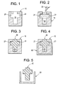
FIG. 1 is a cross-sectional schematic illustration of a formation of a cast component; -
FIG. 2 is a cross-sectional schematic illustration of an introduction of a non-solid material into an interior of the cast component; -
FIG. 3 is a cross-sectional schematic illustration of the non-solid material having been solidified to form an inner shell; -
FIG. 4 is a cross-sectional schematic illustration of a formation of an outer shell; and -
FIG. 5 is a cross-sectional schematic illustration of a removal of the cast component from between the inner and outer shells. - The detailed description explains embodiments of the invention, together with advantages and features, by way of example with reference to the drawings.
- With reference to
FIGS. 1-5 , a process for preparing for casting is provided for formation of, for example, a swirler or swozzle component of a gas turbine engine. The process can be used to create production style swozzles/swirlers with complex interior geometries for lab test evaluation without the expense of ceramic core and wrapper die production style tooling. Limited production volumes could also utilize this concept to reduce part cost and lead time. - As shown in
FIG. 1 , the process includes forming acast component 10 defining aninterior 20 having a complex and/or irregular shape, such as a shape of the swirler or swozzle component or any other desired similarly complex/irregular shape. While the process described herein can be applicable for the formation of a component of any shape with any degree of complexity, theinterior 20 can have a particularly complex shape withinternal cavities 21 and/or other irregular features, as would be the case for swirler or swozzle components. In accordance with various embodiments, the forming of thecast component 10 may include any one or more of stereolithographic (SLA) processes, direct metal laser sintering (DMLS) processes and selective laser sintering (SLS) processes. Thecast component 10 may include a plastic material or another similar type of material. - As shown in
FIG. 2 , anon-solid material 30 is then introduced into thecast component interior 20 to fill thecast component interior 20 and, in particular, to fill theinternal cavities 21 and/or the other irregular features. Thenon-solid material 30 may include any one or more of ceramic slurry and powder. The introducing operation may be achieved, for example, by way of an injection of thenon-solid material 30 into thecast component interior 20, a vacuum assisted injection whereby thenon-solid material 30 is pulled or pressured into thecast component interior 20 and/or plugging whereby thenon-solid material 30 is pushed into thecast component interior 20. - The introducing operation of
FIG. 2 continues until thecast component interior 20 is filled with thenon-solid material 30 and can be facilitated by various additional operations. For example, thecast component 10 may be rotated about a longitudinal axis thereof during and after the introducing operation to thereby urge filling of theinternal cavities 21 and/or the other irregular features by centrifugal force. Rotation may be particularly useful where the non-solid material is the ceramic slurry. In addition, thecast component 10 may be vibrated with vibration being particularly useful where thenon-solid material 30 is powdered. - As shown in
FIG. 3 , the non-solid material is solidified to form aninner shell 40 that matches the shape of thecast component interior 20 including theinternal cavities 21 and/or the other irregular features. In this way, theinner shell 40 may also substantially match an interior shape of the part being produced. The solidifying can be achieved in various manners in accordance with a type of thenon-solid material 30. For example, if thenon-solid material 30 is ceramic slurry, the solidifying operation may include a heat/dry curing of the ceramic slurry to form a ceramicinner shell 40. - As shown in
FIG. 4 , anouter shell 50 is then formed about thecast component 10 to have a shape and size that is substantially similar to an outer surface of thecast component 10. In this way, theouter shell 50 may have a shape and a size that is also substantially similar to that of the part being produced. Formation of theouter shell 50 can be achieved by way of investment casting or other similar casting processes. Theouter shell 50 may be coupled to theinner shell 40 as a result or may be separate from theinner shell 40. - As shown in
FIG. 5 , material of thecast component 10 is removed from between theinner shell 40 and theouter shell 50 by, for example, burning the material of thecast component 10 and washing out residual ash/waste produced by the burning from between theinner shell 40 and theouter shell 50. Theinner shell 40 and theouter shell 50 thus form a finished component as a shelled and ceramic-cored prototype that is ready for, for example, an investment cast metal pour. - While the invention has been described in detail in connection with only a limited number of embodiments, it should be readily understood that the invention is not limited to such disclosed embodiments. Rather, the invention can be modified to incorporate any number of variations, alterations, substitutions or equivalent arrangements not heretofore described, but which are commensurate with the spirit and scope of the invention. Additionally, while various embodiments of the invention have been described, it is to be understood that aspects of the invention may include only some of the described embodiments. Accordingly, the invention is not to be seen as limited by the foregoing description, but is only limited by the scope of the appended claims.
Claims (10)
- A process for preparing for casting, comprising:forming a cast component (10) defining an interior (20) having a complex and/or irregular shape;introducing a non-solid material (30) into the cast component interior (20) and solidifying the non-solid material (30) to form an inner shell (40);forming an outer shell (50) about the cast component (10); andremoving the cast component (10) from between the inner and outer shells (40, 50).
- The process according to claim 1, wherein the forming comprises one or more of stereolithography (SLA), direct metal laser sintering (DMLS) and selective laser sintering (SLS).
- The process according to claim 1 or 2, wherein the cast component (10) is formed in a shape of a swozzle component of a gas turbine engine.
- The process according to claim 1 or 2, wherein the cast component (10) is formed in a shape of a swirler component of a gas turbine engine.
- The process according to any of claims 1 to 4, wherein the cast component (10) comprises a plastic material.
- The process according to any of claims 1 to 5, wherein the non-solid material (30) comprises one of ceramic slurry and powder.
- The process according to any preceding claim, wherein the introducing comprises filling the cast component interior (20) with the non-solid material (30).
- The process according to any preceding claim, wherein the introducing comprises rotating the cast component (10) and the introduced non-solid material (30).
- The process according to any preceding claim, wherein the forming of the outer shell (50) comprises investment casting.
- The process according to any preceding claim, wherein the removing comprises:burning the cast component (10); andwashing out residual ash/waste produced by the burning from between the inner and outer shells (40, 50).
Applications Claiming Priority (1)
| Application Number | Priority Date | Filing Date | Title |
|---|---|---|---|
| US13/094,491 US20120274005A1 (en) | 2011-04-26 | 2011-04-26 | Process for preparing for casting |
Publications (2)
| Publication Number | Publication Date |
|---|---|
| EP2517808A2 true EP2517808A2 (en) | 2012-10-31 |
| EP2517808A3 EP2517808A3 (en) | 2014-09-10 |
Family
ID=45999710
Family Applications (1)
| Application Number | Title | Priority Date | Filing Date |
|---|---|---|---|
| EP12165065.9A Withdrawn EP2517808A3 (en) | 2011-04-26 | 2012-04-20 | Process for preparing a mold for casting |
Country Status (3)
| Country | Link |
|---|---|
| US (1) | US20120274005A1 (en) |
| EP (1) | EP2517808A3 (en) |
| CN (1) | CN102756081A (en) |
Families Citing this family (5)
| Publication number | Priority date | Publication date | Assignee | Title |
|---|---|---|---|---|
| CN105599299A (en) * | 2016-01-07 | 2016-05-25 | 北京无线电测量研究所 | 3D printing processing technology of LTCC substrate cavity filling mold |
| EP3429832B1 (en) | 2016-03-14 | 2021-08-25 | Addifab ApS | Additive manufacturing device and system for manufacturing a sacrificial mould for creating an object |
| US11969918B2 (en) | 2017-07-14 | 2024-04-30 | Nexa3D Aps | Sacrificial additively manufactured molds for use in injection molding processes |
| CN109530628B (en) * | 2018-12-07 | 2020-09-29 | 武汉大学深圳研究院 | Supersonic nozzle manufacturing method for generating cluster beams |
| DE102019200212A1 (en) * | 2019-01-10 | 2020-07-16 | Lechler Gmbh | Process for producing a negative mold for a spiral nozzle, spiral basic mold positive and spiral nozzle |
Family Cites Families (5)
| Publication number | Priority date | Publication date | Assignee | Title |
|---|---|---|---|---|
| US6177034B1 (en) * | 1998-04-03 | 2001-01-23 | A-Pear Biometric Replications Inc. | Methods for making prosthetic surfaces |
| US20050006047A1 (en) * | 2003-07-10 | 2005-01-13 | General Electric Company | Investment casting method and cores and dies used therein |
| WO2005056266A1 (en) * | 2003-12-12 | 2005-06-23 | Shonan Design Co., Ltd | Method for manufacturing hollow model |
| US7448433B2 (en) * | 2004-09-24 | 2008-11-11 | Honeywell International Inc. | Rapid prototype casting |
| EP1661640A1 (en) * | 2004-11-24 | 2006-05-31 | Siemens Aktiengesellschaft | Method for producing a lost pattern and a core introduced into the pattern |
-
2011
- 2011-04-26 US US13/094,491 patent/US20120274005A1/en not_active Abandoned
-
2012
- 2012-04-20 EP EP12165065.9A patent/EP2517808A3/en not_active Withdrawn
- 2012-04-25 CN CN201210138305XA patent/CN102756081A/en active Pending
Non-Patent Citations (1)
| Title |
|---|
| None |
Also Published As
| Publication number | Publication date |
|---|---|
| CN102756081A (en) | 2012-10-31 |
| US20120274005A1 (en) | 2012-11-01 |
| EP2517808A3 (en) | 2014-09-10 |
Similar Documents
| Publication | Publication Date | Title |
|---|---|---|
| EP2517808A2 (en) | Process for preparing a mold for casting | |
| JP6000629B2 (en) | Ceramic core with composite inserts used for airfoil casting | |
| CN105834360B (en) | The casting method of shell mould is made using 3D printing | |
| CN109729713A (en) | Manufacture the Rapid prototyping methods of the tooling of injection molding | |
| CN103567384B (en) | The method for manufacturing rotor | |
| JP6057598B2 (en) | Method for producing sintered metal powder having hollow portion | |
| US11548232B2 (en) | Method of manufacturing isotropic parts utilizing additive manufacturing methods | |
| CN108971486B (en) | Method and apparatus for growing compression chambers in powder-based additive manufacturing to reduce powder loading on growing parts | |
| Ong et al. | Rapid moulding using epoxy tooling resin | |
| KR20170079937A (en) | Method of casting by 3D printing mold | |
| CN110891715A (en) | Method for producing parts with complex shape by metal powder injection moulding | |
| CN107000036A (en) | Method for manufacturing compressor impeller | |
| KR20200087217A (en) | Mold assembly for manufacturing parts and manufacturing method of mold assembly | |
| JP7673936B2 (en) | Method for producing moldings, in particular dental moldings | |
| CN102413969B (en) | Comprise the manufacture method of the assembly of multiple blade be arranged in platform | |
| CN108237202A (en) | Combination technique investment casting process | |
| Singh et al. | Investigations for reducing wall thickness of aluminium shell casting using three dimensional printing | |
| CN109311093B (en) | Methods, enclosures and apparatus for making components | |
| Harun et al. | Characteristic studies of collapsibility of ABS patterns produced from FDM for investment casting | |
| CN114206528A (en) | Method for producing a metal part | |
| JP6897538B2 (en) | Core molding method and molding equipment | |
| CN205270740U (en) | Adopt 3D to print vacuum casting device of shell mould | |
| JP2003183705A5 (en) | ||
| US20170361490A1 (en) | Process for manufacturing a ceramic turbine blade | |
| RU2641683C1 (en) | Method of producing ceramic products of complex volume form |
Legal Events
| Date | Code | Title | Description |
|---|---|---|---|
| PUAI | Public reference made under article 153(3) epc to a published international application that has entered the european phase |
Free format text: ORIGINAL CODE: 0009012 |
|
| AK | Designated contracting states |
Kind code of ref document: A2 Designated state(s): AL AT BE BG CH CY CZ DE DK EE ES FI FR GB GR HR HU IE IS IT LI LT LU LV MC MK MT NL NO PL PT RO RS SE SI SK SM TR |
|
| AX | Request for extension of the european patent |
Extension state: BA ME |
|
| PUAL | Search report despatched |
Free format text: ORIGINAL CODE: 0009013 |
|
| AK | Designated contracting states |
Kind code of ref document: A3 Designated state(s): AL AT BE BG CH CY CZ DE DK EE ES FI FR GB GR HR HU IE IS IT LI LT LU LV MC MK MT NL NO PL PT RO RS SE SI SK SM TR |
|
| AX | Request for extension of the european patent |
Extension state: BA ME |
|
| RIC1 | Information provided on ipc code assigned before grant |
Ipc: B22C 9/04 20060101AFI20140806BHEP Ipc: B29C 67/00 20060101ALI20140806BHEP |
|
| STAA | Information on the status of an ep patent application or granted ep patent |
Free format text: STATUS: THE APPLICATION IS DEEMED TO BE WITHDRAWN |
|
| 18D | Application deemed to be withdrawn |
Effective date: 20141101 |