EP2517632A2 - Fenestration sealing device - Google Patents
Fenestration sealing device Download PDFInfo
- Publication number
- EP2517632A2 EP2517632A2 EP12275052A EP12275052A EP2517632A2 EP 2517632 A2 EP2517632 A2 EP 2517632A2 EP 12275052 A EP12275052 A EP 12275052A EP 12275052 A EP12275052 A EP 12275052A EP 2517632 A2 EP2517632 A2 EP 2517632A2
- Authority
- EP
- European Patent Office
- Prior art keywords
- fenestration
- sealing
- sealing device
- sealing member
- biasing
- Prior art date
- Legal status (The legal status is an assumption and is not a legal conclusion. Google has not performed a legal analysis and makes no representation as to the accuracy of the status listed.)
- Withdrawn
Links
- 238000007789 sealing Methods 0.000 title claims abstract description 139
- 239000000463 material Substances 0.000 claims description 13
- 239000008280 blood Substances 0.000 abstract description 5
- 210000004369 blood Anatomy 0.000 abstract description 5
- 210000004876 tela submucosa Anatomy 0.000 description 7
- PXHVJJICTQNCMI-UHFFFAOYSA-N Nickel Chemical compound [Ni] PXHVJJICTQNCMI-UHFFFAOYSA-N 0.000 description 4
- 229910045601 alloy Inorganic materials 0.000 description 4
- 239000000956 alloy Substances 0.000 description 4
- 229910001000 nickel titanium Inorganic materials 0.000 description 4
- HLXZNVUGXRDIFK-UHFFFAOYSA-N nickel titanium Chemical compound [Ti].[Ti].[Ti].[Ti].[Ti].[Ti].[Ti].[Ti].[Ti].[Ti].[Ti].[Ni].[Ni].[Ni].[Ni].[Ni].[Ni].[Ni].[Ni].[Ni].[Ni].[Ni].[Ni].[Ni].[Ni] HLXZNVUGXRDIFK-UHFFFAOYSA-N 0.000 description 4
- 102000008186 Collagen Human genes 0.000 description 3
- 108010035532 Collagen Proteins 0.000 description 3
- RTAQQCXQSZGOHL-UHFFFAOYSA-N Titanium Chemical compound [Ti] RTAQQCXQSZGOHL-UHFFFAOYSA-N 0.000 description 3
- 230000017531 blood circulation Effects 0.000 description 3
- 229920001436 collagen Polymers 0.000 description 3
- 229910052719 titanium Inorganic materials 0.000 description 3
- 239000010936 titanium Substances 0.000 description 3
- 102000010834 Extracellular Matrix Proteins Human genes 0.000 description 2
- 108010037362 Extracellular Matrix Proteins Proteins 0.000 description 2
- 210000003484 anatomy Anatomy 0.000 description 2
- 210000002469 basement membrane Anatomy 0.000 description 2
- 238000006073 displacement reaction Methods 0.000 description 2
- 210000002744 extracellular matrix Anatomy 0.000 description 2
- 230000000968 intestinal effect Effects 0.000 description 2
- 229910052751 metal Inorganic materials 0.000 description 2
- 239000002184 metal Substances 0.000 description 2
- 150000002739 metals Chemical class 0.000 description 2
- 238000000034 method Methods 0.000 description 2
- 238000012986 modification Methods 0.000 description 2
- 230000004048 modification Effects 0.000 description 2
- 229910052759 nickel Inorganic materials 0.000 description 2
- BASFCYQUMIYNBI-UHFFFAOYSA-N platinum Chemical compound [Pt] BASFCYQUMIYNBI-UHFFFAOYSA-N 0.000 description 2
- -1 polytetrafluoroethylene Polymers 0.000 description 2
- 229910001285 shape-memory alloy Inorganic materials 0.000 description 2
- 229910000684 Cobalt-chrome Inorganic materials 0.000 description 1
- 229920004934 Dacron® Polymers 0.000 description 1
- 239000004952 Polyamide Substances 0.000 description 1
- 201000008982 Thoracic Aortic Aneurysm Diseases 0.000 description 1
- 208000002223 abdominal aortic aneurysm Diseases 0.000 description 1
- 210000000709 aorta Anatomy 0.000 description 1
- 208000007474 aortic aneurysm Diseases 0.000 description 1
- 239000012620 biological material Substances 0.000 description 1
- 239000002775 capsule Substances 0.000 description 1
- 239000010952 cobalt-chrome Substances 0.000 description 1
- 230000001419 dependent effect Effects 0.000 description 1
- 210000001951 dura mater Anatomy 0.000 description 1
- 230000002500 effect on skin Effects 0.000 description 1
- 229920000295 expanded polytetrafluoroethylene Polymers 0.000 description 1
- 210000000109 fascia lata Anatomy 0.000 description 1
- 210000001105 femoral artery Anatomy 0.000 description 1
- 239000012530 fluid Substances 0.000 description 1
- PCHJSUWPFVWCPO-UHFFFAOYSA-N gold Chemical compound [Au] PCHJSUWPFVWCPO-UHFFFAOYSA-N 0.000 description 1
- 229910052737 gold Inorganic materials 0.000 description 1
- 239000010931 gold Substances 0.000 description 1
- 230000000004 hemodynamic effect Effects 0.000 description 1
- 210000003090 iliac artery Anatomy 0.000 description 1
- 238000003384 imaging method Methods 0.000 description 1
- 239000007943 implant Substances 0.000 description 1
- 238000003780 insertion Methods 0.000 description 1
- 230000037431 insertion Effects 0.000 description 1
- 210000004185 liver Anatomy 0.000 description 1
- 230000007246 mechanism Effects 0.000 description 1
- 210000004379 membrane Anatomy 0.000 description 1
- 239000012528 membrane Substances 0.000 description 1
- 239000007769 metal material Substances 0.000 description 1
- 210000003516 pericardium Anatomy 0.000 description 1
- 210000004303 peritoneum Anatomy 0.000 description 1
- 229910052697 platinum Inorganic materials 0.000 description 1
- 229920002647 polyamide Polymers 0.000 description 1
- 239000005020 polyethylene terephthalate Substances 0.000 description 1
- 229920000642 polymer Polymers 0.000 description 1
- 229920001343 polytetrafluoroethylene Polymers 0.000 description 1
- 239000004810 polytetrafluoroethylene Substances 0.000 description 1
- 230000003014 reinforcing effect Effects 0.000 description 1
- 230000000241 respiratory effect Effects 0.000 description 1
- 239000010935 stainless steel Substances 0.000 description 1
- 229910001220 stainless steel Inorganic materials 0.000 description 1
- 210000002784 stomach Anatomy 0.000 description 1
- 229910052715 tantalum Inorganic materials 0.000 description 1
- GUVRBAGPIYLISA-UHFFFAOYSA-N tantalum atom Chemical compound [Ta] GUVRBAGPIYLISA-UHFFFAOYSA-N 0.000 description 1
- 229920001169 thermoplastic Polymers 0.000 description 1
- 239000004416 thermosoftening plastic Substances 0.000 description 1
- 210000003932 urinary bladder Anatomy 0.000 description 1
Images



Classifications
-
- A—HUMAN NECESSITIES
- A61—MEDICAL OR VETERINARY SCIENCE; HYGIENE
- A61B—DIAGNOSIS; SURGERY; IDENTIFICATION
- A61B17/00—Surgical instruments, devices or methods
- A61B17/0057—Implements for plugging an opening in the wall of a hollow or tubular organ, e.g. for sealing a vessel puncture or closing a cardiac septal defect
-
- A—HUMAN NECESSITIES
- A61—MEDICAL OR VETERINARY SCIENCE; HYGIENE
- A61F—FILTERS IMPLANTABLE INTO BLOOD VESSELS; PROSTHESES; DEVICES PROVIDING PATENCY TO, OR PREVENTING COLLAPSING OF, TUBULAR STRUCTURES OF THE BODY, e.g. STENTS; ORTHOPAEDIC, NURSING OR CONTRACEPTIVE DEVICES; FOMENTATION; TREATMENT OR PROTECTION OF EYES OR EARS; BANDAGES, DRESSINGS OR ABSORBENT PADS; FIRST-AID KITS
- A61F2/00—Filters implantable into blood vessels; Prostheses, i.e. artificial substitutes or replacements for parts of the body; Appliances for connecting them with the body; Devices providing patency to, or preventing collapsing of, tubular structures of the body, e.g. stents
- A61F2/02—Prostheses implantable into the body
- A61F2/04—Hollow or tubular parts of organs, e.g. bladders, tracheae, bronchi or bile ducts
- A61F2/06—Blood vessels
- A61F2/07—Stent-grafts
-
- A—HUMAN NECESSITIES
- A61—MEDICAL OR VETERINARY SCIENCE; HYGIENE
- A61B—DIAGNOSIS; SURGERY; IDENTIFICATION
- A61B17/00—Surgical instruments, devices or methods
- A61B17/0057—Implements for plugging an opening in the wall of a hollow or tubular organ, e.g. for sealing a vessel puncture or closing a cardiac septal defect
- A61B2017/00575—Implements for plugging an opening in the wall of a hollow or tubular organ, e.g. for sealing a vessel puncture or closing a cardiac septal defect for closure at remote site, e.g. closing atrial septum defects
- A61B2017/00592—Elastic or resilient implements
-
- A—HUMAN NECESSITIES
- A61—MEDICAL OR VETERINARY SCIENCE; HYGIENE
- A61B—DIAGNOSIS; SURGERY; IDENTIFICATION
- A61B17/00—Surgical instruments, devices or methods
- A61B17/0057—Implements for plugging an opening in the wall of a hollow or tubular organ, e.g. for sealing a vessel puncture or closing a cardiac septal defect
- A61B2017/00575—Implements for plugging an opening in the wall of a hollow or tubular organ, e.g. for sealing a vessel puncture or closing a cardiac septal defect for closure at remote site, e.g. closing atrial septum defects
- A61B2017/00597—Implements comprising a membrane
-
- A—HUMAN NECESSITIES
- A61—MEDICAL OR VETERINARY SCIENCE; HYGIENE
- A61B—DIAGNOSIS; SURGERY; IDENTIFICATION
- A61B17/00—Surgical instruments, devices or methods
- A61B17/0057—Implements for plugging an opening in the wall of a hollow or tubular organ, e.g. for sealing a vessel puncture or closing a cardiac septal defect
- A61B2017/00575—Implements for plugging an opening in the wall of a hollow or tubular organ, e.g. for sealing a vessel puncture or closing a cardiac septal defect for closure at remote site, e.g. closing atrial septum defects
- A61B2017/00606—Implements H-shaped in cross-section, i.e. with occluders on both sides of the opening
-
- A—HUMAN NECESSITIES
- A61—MEDICAL OR VETERINARY SCIENCE; HYGIENE
- A61B—DIAGNOSIS; SURGERY; IDENTIFICATION
- A61B17/00—Surgical instruments, devices or methods
- A61B17/0057—Implements for plugging an opening in the wall of a hollow or tubular organ, e.g. for sealing a vessel puncture or closing a cardiac septal defect
- A61B2017/00575—Implements for plugging an opening in the wall of a hollow or tubular organ, e.g. for sealing a vessel puncture or closing a cardiac septal defect for closure at remote site, e.g. closing atrial septum defects
- A61B2017/00615—Implements with an occluder on one side of the opening and holding means therefor on the other
-
- A—HUMAN NECESSITIES
- A61—MEDICAL OR VETERINARY SCIENCE; HYGIENE
- A61B—DIAGNOSIS; SURGERY; IDENTIFICATION
- A61B17/00—Surgical instruments, devices or methods
- A61B17/0057—Implements for plugging an opening in the wall of a hollow or tubular organ, e.g. for sealing a vessel puncture or closing a cardiac septal defect
- A61B2017/00575—Implements for plugging an opening in the wall of a hollow or tubular organ, e.g. for sealing a vessel puncture or closing a cardiac septal defect for closure at remote site, e.g. closing atrial septum defects
- A61B2017/00623—Introducing or retrieving devices therefor
-
- A—HUMAN NECESSITIES
- A61—MEDICAL OR VETERINARY SCIENCE; HYGIENE
- A61B—DIAGNOSIS; SURGERY; IDENTIFICATION
- A61B17/00—Surgical instruments, devices or methods
- A61B17/0057—Implements for plugging an opening in the wall of a hollow or tubular organ, e.g. for sealing a vessel puncture or closing a cardiac septal defect
- A61B2017/00646—Type of implements
- A61B2017/00668—Type of implements the implement being a tack or a staple
-
- A—HUMAN NECESSITIES
- A61—MEDICAL OR VETERINARY SCIENCE; HYGIENE
- A61F—FILTERS IMPLANTABLE INTO BLOOD VESSELS; PROSTHESES; DEVICES PROVIDING PATENCY TO, OR PREVENTING COLLAPSING OF, TUBULAR STRUCTURES OF THE BODY, e.g. STENTS; ORTHOPAEDIC, NURSING OR CONTRACEPTIVE DEVICES; FOMENTATION; TREATMENT OR PROTECTION OF EYES OR EARS; BANDAGES, DRESSINGS OR ABSORBENT PADS; FIRST-AID KITS
- A61F2/00—Filters implantable into blood vessels; Prostheses, i.e. artificial substitutes or replacements for parts of the body; Appliances for connecting them with the body; Devices providing patency to, or preventing collapsing of, tubular structures of the body, e.g. stents
- A61F2/02—Prostheses implantable into the body
- A61F2/04—Hollow or tubular parts of organs, e.g. bladders, tracheae, bronchi or bile ducts
- A61F2/06—Blood vessels
- A61F2002/061—Blood vessels provided with means for allowing access to secondary lumens
-
- A—HUMAN NECESSITIES
- A61—MEDICAL OR VETERINARY SCIENCE; HYGIENE
- A61F—FILTERS IMPLANTABLE INTO BLOOD VESSELS; PROSTHESES; DEVICES PROVIDING PATENCY TO, OR PREVENTING COLLAPSING OF, TUBULAR STRUCTURES OF THE BODY, e.g. STENTS; ORTHOPAEDIC, NURSING OR CONTRACEPTIVE DEVICES; FOMENTATION; TREATMENT OR PROTECTION OF EYES OR EARS; BANDAGES, DRESSINGS OR ABSORBENT PADS; FIRST-AID KITS
- A61F2220/00—Fixations or connections for prostheses classified in groups A61F2/00 - A61F2/26 or A61F2/82 or A61F9/00 or A61F11/00 or subgroups thereof
- A61F2220/0025—Connections or couplings between prosthetic parts, e.g. between modular parts; Connecting elements
- A61F2220/005—Connections or couplings between prosthetic parts, e.g. between modular parts; Connecting elements using adhesives
-
- A—HUMAN NECESSITIES
- A61—MEDICAL OR VETERINARY SCIENCE; HYGIENE
- A61F—FILTERS IMPLANTABLE INTO BLOOD VESSELS; PROSTHESES; DEVICES PROVIDING PATENCY TO, OR PREVENTING COLLAPSING OF, TUBULAR STRUCTURES OF THE BODY, e.g. STENTS; ORTHOPAEDIC, NURSING OR CONTRACEPTIVE DEVICES; FOMENTATION; TREATMENT OR PROTECTION OF EYES OR EARS; BANDAGES, DRESSINGS OR ABSORBENT PADS; FIRST-AID KITS
- A61F2220/00—Fixations or connections for prostheses classified in groups A61F2/00 - A61F2/26 or A61F2/82 or A61F9/00 or A61F11/00 or subgroups thereof
- A61F2220/0025—Connections or couplings between prosthetic parts, e.g. between modular parts; Connecting elements
- A61F2220/0066—Connections or couplings between prosthetic parts, e.g. between modular parts; Connecting elements stapled
-
- A—HUMAN NECESSITIES
- A61—MEDICAL OR VETERINARY SCIENCE; HYGIENE
- A61F—FILTERS IMPLANTABLE INTO BLOOD VESSELS; PROSTHESES; DEVICES PROVIDING PATENCY TO, OR PREVENTING COLLAPSING OF, TUBULAR STRUCTURES OF THE BODY, e.g. STENTS; ORTHOPAEDIC, NURSING OR CONTRACEPTIVE DEVICES; FOMENTATION; TREATMENT OR PROTECTION OF EYES OR EARS; BANDAGES, DRESSINGS OR ABSORBENT PADS; FIRST-AID KITS
- A61F2220/00—Fixations or connections for prostheses classified in groups A61F2/00 - A61F2/26 or A61F2/82 or A61F9/00 or A61F11/00 or subgroups thereof
- A61F2220/0025—Connections or couplings between prosthetic parts, e.g. between modular parts; Connecting elements
- A61F2220/0075—Connections or couplings between prosthetic parts, e.g. between modular parts; Connecting elements sutured, ligatured or stitched, retained or tied with a rope, string, thread, wire or cable
-
- A—HUMAN NECESSITIES
- A61—MEDICAL OR VETERINARY SCIENCE; HYGIENE
- A61F—FILTERS IMPLANTABLE INTO BLOOD VESSELS; PROSTHESES; DEVICES PROVIDING PATENCY TO, OR PREVENTING COLLAPSING OF, TUBULAR STRUCTURES OF THE BODY, e.g. STENTS; ORTHOPAEDIC, NURSING OR CONTRACEPTIVE DEVICES; FOMENTATION; TREATMENT OR PROTECTION OF EYES OR EARS; BANDAGES, DRESSINGS OR ABSORBENT PADS; FIRST-AID KITS
- A61F2250/00—Special features of prostheses classified in groups A61F2/00 - A61F2/26 or A61F2/82 or A61F9/00 or A61F11/00 or subgroups thereof
- A61F2250/0058—Additional features; Implant or prostheses properties not otherwise provided for
- A61F2250/0069—Sealing means
Definitions
- the present invention relates to a sealing device for sealing a fenestration within a graft.
- Fenestrated devices such as grafts and stent grafts for treating aortic aneurysms, such as abdominal aortic aneurysms and thoracic aortic aneurysms, are known for use in treating conditions of body vessels where the body vessel has one or more branch vessels so as not to obstruct the branch vessel. Because of the vagaries of individual patient anatomy, precise placement of the fenestration to align with the orifice of the branch vessel may present a challenge. For example, the anatomy of the patient may have changed from the time of imaging the location of the branching vessel(s) to the time of placement of the device.
- a device that has two or more fenestrations in the graft that may be selected from for alignment with the branch vessel. Once the appropriate fenestration is aligned with the vessel, the other fenestrations would need to be sealed.
- fenestrations in such devices also may be used for catheter access or for access by other devices. Once the required access is no longer needed, the fenestration would need to be sealed to avoid leakage.
- Some devices are used to seal a fenestration that is not needed or no longer required for access.
- a valve or flap arrangement may be used to seal the fenestration from the inner portion of the stent graft.
- These types of sealing devices typically require that the device be inserted along with the bifurcated stent graft and placed in the expanded configurations. In order to access the fenestration, the catheter must be maneuvered between the valve or flap and the inner wall of the stent graft to gain access to the area outside of the stent graft.
- the present invention seeks to provide improved sealing of grafts.
- An aspect of the present invention provides a sealing device as specified in claim 1.
- a sealing device for sealing a fenestration in a wall of a prosthesis such as a graft or stent-graft.
- the prosthesis has an interior surface and an exterior surface.
- the sealing device includes a sealing member that has an exterior face and an interior face, and an outer diameter that is greater than the diameter of the fenestration.
- the sealing device also includes a biasing member that extends from the exterior face of the sealing member. The biasing member extends through the fenestration, for example of a tubular graft, and applies a force against the exterior surface of the graft to cause the sealing member to abut the inside surface of the graft around the fenestration.
- the biasing member may include at least two biasing fingers coupled to the sealing member, where the at least two biasing fingers extend away from the exterior face of the sealing member and are configured to extend through the fenestration and apply a force against exterior portion of the graft to cause the sealing member to sealing abut the fenestration.
- a sealing device for sealing a fenestration within a graft
- the sealing device comprising a sealing member having an exterior face and an interior face, where the outer diameter of the sealing member is greater than the outer diameter of the fenestration; and at least two biasing fingers coupled to the sealing member, where the at least two biasing fingers extend away from the exterior face of the sealing member and are configured to extend through the fenestration and apply a force against an exterior portion of the graft to cause the sealing member to abut the fenestration.
- the present embodiments relate to a sealing device used to seal a fenestration formed within a stent graft where the sealing device includes a sealing member to abut the fenestration and a biasing member to maintain the sealing member in a position adjacent to the fenestration to prevent blood from escaping through the fenestration.
- Methods of delivery and placement of the sealing device to seal a fenestration are also shown and described herein.
- the sealing device 10 includes a sealing member 12 having an exterior face 14 and an interior face 16.
- the sealing member 12 may be made out of graft material that is commonly used and available, such as polytetrafluoroethylene (ePTFE), Thoralon TM , Dacron, polyamide or any other suitable biocompatible graft material.
- ePTFE polytetrafluoroethylene
- Thoralon TM Thoralon TM
- Dacron polyamide
- a naturally occurring biomaterial, such as collagen may also be suitable, particularly a specially derived collagen material known as an extracellular matrix (ECM) material, such as submucosa, renal capsule membrane, dermal collagen, dura mater, pericardium, fascia lata, serosa, peritoneum or basement membrane layers, including liver basement membrane.
- ECM extracellular matrix
- Suitable submucosa materials for these purposes include, for instance, intestinal submucosa, including small intestinal submucosa (SIS), stomach submucosa, urinary bladder submucosa, and uterine submucosa.
- intestinal submucosa including small intestinal submucosa (SIS), stomach submucosa, urinary bladder submucosa, and uterine submucosa.
- the sealing member 12 is circular in shape and has a substantially constant thickness; however, it is appreciated that the shape and thickness may be varied depending on the particular application that it is being used for.
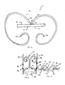
- Attached to the sealing member 12 is a biasing member 18, as shown in Figure 1 .
- the biasing member 18 may be connected to the sealing member 12 in a plurality of ways, including being anchored, stitched, adhered, or using mechanical devices such as clamps, clips, snap-fit arrangements, and the like. Additionally, other mechanisms known now or that may become known to one of skill in the art may be used to connect the biasing member 18 to the sealing member 12.
- the biasing member 18 may be attached to a frame or be formed as part of the reinforcing member.
- the biasing member 18 comprises two biasing fingers 20, each having a first end 22 and a second end 24.
- the first end 22 of each biasing finger 20 is secured to the sealing member 12 in a manner identified above.
- the second end 24 of the biasing finger 20 may have a curved or helical shape to help center the sealing device with respect to a fenestration.
- the curved shape may also help allow the biasing fingers 20 to rotate with respect to the outer wall 28 of the stent graft 26 to pull the sealing member 12 against the fenestration 30.
- the types of material from which the biasing fingers 20 may be manufactured include a shape memory alloy comprised of Nickel and Titanium, which is commonly referred to as Nitinol, and Teritary alloys (or "Nitinol").
- the biasing fingers 20 may be made from other metals and alloys that are biased, such that they may be restrained prior to deployment, but are inclined to return to their relaxed, expanded configuration upon deployment. Solely by way of example, the biasing fingers 20 may comprise other materials such as stainless steel, cobalt-chrome alloys, amorphous metals, tantalum, platinum, gold and titanium, or may be made from non-metallic materials, such as thermoplastics and other polymers.
- the biasing fingers 20 of the sealing device when in a natural state, originate from the exterior face 14 and curl around the sides of the sealing member 12.
- the preformed curve of the biasing fingers 20 in the natural state as shown in Figure 2 allow the sealing device 10 to seal the fenestration 30 and prevent fluids, such as blood, from escaping from the stent graft.
- the biasing fingers supply sufficient force against an outer wall 28 of the stent graft 26 to effectively pull the sealing member 12 against the fenestration 30.
- the amount of force required is application and material dependent, for example the thickness or rigidity of the material, and is preferably in excess of the displacement forces.
- Displacement forces may include hemodynamic forces, physical forces, respiratory forces and any other forces that might act upon the sealing member,
- the biasing fingers 20 typically have an outer diameter ranging from about 0.3mm to about 1.5mm, and may comprise a length of about 2.0 mm to about 30.0mm.
- the outer diameter of each biasing finger 20 may vary along its length and the length of the each of the biasing fingers 20 for a particular application may vary.
- the number of biasing fingers 20 may vary depending on a particular application.
- Figure 2 illustrates a side view of the sealing device 10 secured to the outer wall 28 of the stent graft 26 to seal the fenestration 30.
- the biasing fingers 20 are biased against the outer wall 28 of the stent graft 26 such that the sealing member 12 is pulled flush against the fenestration 30, thereby sealing the fenestration 30 to prevent blood from escaping therethrough.
- the curved shape of the second ends 24 of the biasing fingers 20 encourage the fingers 20 to curl, thereby increasing the biasing force and further securing the sealing member 12 against the inner wall 32 of the stent graft 26 surrounding the fenestration 30.
- the exterior face 14 of the sealing member 12 has an area greater than the area formed by the fenestration 30 to effectively seal the opening.
- the amount of overlap between the sealing member 12 on the inner wall 32 of the stent graft 26 is determined based at least in part on the amount of pressure exerted by the blood flowing through the stent graft 26 and the biasing force exerted by the biasing member 18. In most cases, the amount of overlap may be between about 0.5 and about 10.0 mm.
- the sealing device may comprise a diameter of 10% or more greater than the diameter of the fenestrations.
- the sealing device may be asymmetrically shaped or oppose the convexity of the aortic graft to achieve a better seal and fixation over the fenestration.
- the exterior face 14 of the sealing member may have a rough surface along its outer portion so as to enhance the frictional force as that portion comes into contact with the inner wall 32 of the stent graft 26.
- the outer edges 34 of the sealing member 12 may be tapered, as shown in dashed lines on Figures 1 and 2 .
- the tapering of the edges of the sealing member 12 will reduce the disruption of the blood flow through the stent graft 26.
- the amount of taper may vary between about 0.1 and about 45.0 degrees to encourage laminar blood flow and to provide a substantially imperceptible gradient between the sealing device and the wall of the stent graft or a hole in the aorta. It can also be appreciated that the entire perimeter of the sealing device 12 may not be tapered but only the portions which are facing the direction of the blood flow.
- the sealing device 10 may have configurations depending on the intended application.
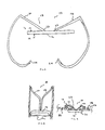
- the sealing devices 10 as shown in Figures 4 and 7 respectively include two biasing members 18 with a more defined angular shape to reduce the overall profile of the sealing device 10 when in the expanded position and when engaged with the stent graft 26 as shown in Figures 5 and 8 , respectively.
- the biasing member 18 is in the form of a helical-shaped coil 36.
- the coil 36 has one end attached to the exterior face 14 of the sealing member 12.
- the coil 36 must be biased towards the sealing member 12, as shown in Figure 11 when in its natural or relaxed state. This will ensure that the sealing member 12 will be held flush against the fenestration 30 as shown in Figure 12 .
- the coil 36 is pressed against the outer wall 28 of the stent graft 26, thereby pulling the sealing member 12 against the fenestration.
- the modifications to the sealing member 12 discussed with respect to the other embodiments also apply here as well.
- the sealing member 12 is secured to a frame 38, which maintains the shape and rigidity of the sealing member 12 when it is deployed adjacent to the fenestration 30.
- the increased rigidity of the sealing member 12 as a result of the frame 38 minimizes the amount of overlap required between the sealing member 12 and portion the stent graft 26 surrounding the fenestration 30 to retain the sealing member 12 against the fenestration 30.
- the biasing member 18 is a circular frame 40 that is configured to be expanded beyond the outer circumference of the fenestration 30 to bias the sealing member 12 against the fenestration 30.
- the circular frame 40 has curved portions 42 that extend beyond the sealing member 12 in the natural or relaxed state. These curved portions 42 can press against the outer wall 28 of the stent graft 26 to pull the sealing member 12 against the inner wall 32 of the stent graft 26 adjacent to the fenestration 30 when disposed through the fenestration 30.
- the circular frame 40 may be attached to the frame 38 in a plurality of ways.
- the circular frame 40 is attached to the frame 38 with two struts 44.
- the struts 44 extend from the frame 38 and connect to the circular frame 40 and are located opposite from one another. It can be appreciated that an alternative number of struts 44 may be used and may be oriented differently with respect to each other.
- the frame 38, circular frame 40, and struts 44 are made out of the same piece of material, which is preferably made out of a shape memory alloy comprised of Nickel and Titanium, which is commonly referred to as Nitinol, and Teritary alloys, commonly referred to as Nitinol.
- the frame members 38, 40 and struts 44 may be made out of different pieces and types of material depending on the particular application.
- FIGs 3 , 6 , 9 , 13 , and 15 depict each of the various embodiments of the sealing device 10 disposed within a delivery system 46.
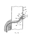
- the delivery system 46 includes a catheter 48 that is positioned through the fenestration 30 as shown in Figure 17 .
- a flexible pusher 50 Positioned within the catheter 48 is a flexible pusher 50 having a disc-shaped end 52 that is used to help place the sealing device 10 in the desired location.
- the sealing device 10 is placed within the catheter 48 in a compressed configuration where the sealing member 12 and biasing member 18 are compressed in order to fit into the catheter 48.
- the compressed configuration of the sealing device 10 minimizes the outer diameter of the catheter 48 that is disposed through the fenestration 30 during the deployment process.
- the sealing member 12 must have a smaller profile than fenestration 30; otherwise the catheter 48 would not be able to fit through the fenestration 30 to deploy the biasing member 18.
- the sealing device 10 Prior to the deployment, the sealing device 10 is positioned such that the biasing member 18 is located adjacent to the fenestration 30 on the outside of the stent graft 26 and the sealing member 12 is located adjacent to the fenestration 30 but is within the stent graft 26. In other words, the fenestration 30 is located between the sealing member 12 and the biasing member 18.
- the sheath 54 of the catheter is retracted while the sealing device 10 remains positionally fixed. As the sheath 54 is retracted, it releases the biasing member 18, such that it expands to its pre-defmed shape, as shown in Figure 18 .
- the sheath 54 is further retracted such that it releases the sealing member 12 within the stent graft 26 and adjacent to the fenestration 30.
- the biasing member 18 pulls the sealing device 12 towards the fenestration 30 thereby sealing the fenestration 30 as shown in Figure 19 .
- the sealing device 10 and/or the delivery system 46 may include radio-opaque markers 56, as shown in Figure 3 .
- the markers 56 enable the sealing device to be properly placed respective to the fenestration 30 and namely ensures that the biasing member 18 is deployed outside of the stent graft and the sealing member 12 is appropriately centered with respect to the fenestration 30 and is deployed within the stent graft 26.
- the delivery system 46 may be deployed through the femoral artery and into the side arm 58 of the stent graft 26. Alternatively, the delivery system 46 may be inserted through one of the legs that is disposed within the iliac artery. It can also be appreciated that the delivery system 46 may be positioned to enter the fenestration 30 from the outside of the stent graft 26 and first deploy the sealing member 12 prior to deploying the biasing member 18. In this scenario, the sealing device 10 will be positioned within the delivery system 46 in the opposite orientation, such that the biasing member 18 would be adjacent to the pusher 50. The remaining steps of deploying the sealing device 10 would be substantially the same as described above. It can be appreciated that depending on the intended use of the sealing device 10, the delivery system 46 may inserted into any other vessel than the ones identified herein.
Landscapes
- Health & Medical Sciences (AREA)
- Life Sciences & Earth Sciences (AREA)
- Animal Behavior & Ethology (AREA)
- Surgery (AREA)
- Veterinary Medicine (AREA)
- Cardiology (AREA)
- Public Health (AREA)
- Engineering & Computer Science (AREA)
- Biomedical Technology (AREA)
- Heart & Thoracic Surgery (AREA)
- General Health & Medical Sciences (AREA)
- Transplantation (AREA)
- Vascular Medicine (AREA)
- Oral & Maxillofacial Surgery (AREA)
- Pulmonology (AREA)
- Nuclear Medicine, Radiotherapy & Molecular Imaging (AREA)
- Gastroenterology & Hepatology (AREA)
- Medical Informatics (AREA)
- Molecular Biology (AREA)
- Prostheses (AREA)
- Surgical Instruments (AREA)
- Media Introduction/Drainage Providing Device (AREA)
Abstract
Description
- The present invention relates to a sealing device for sealing a fenestration within a graft.
- Fenestrated devices, such as grafts and stent grafts for treating aortic aneurysms, such as abdominal aortic aneurysms and thoracic aortic aneurysms, are known for use in treating conditions of body vessels where the body vessel has one or more branch vessels so as not to obstruct the branch vessel. Because of the vagaries of individual patient anatomy, precise placement of the fenestration to align with the orifice of the branch vessel may present a challenge. For example, the anatomy of the patient may have changed from the time of imaging the location of the branching vessel(s) to the time of placement of the device. In such instances, it may be desirable to implant a device that has two or more fenestrations in the graft that may be selected from for alignment with the branch vessel. Once the appropriate fenestration is aligned with the vessel, the other fenestrations would need to be sealed.
- Further, fenestrations in such devices also may be used for catheter access or for access by other devices. Once the required access is no longer needed, the fenestration would need to be sealed to avoid leakage. Some devices are used to seal a fenestration that is not needed or no longer required for access. For example, a valve or flap arrangement may be used to seal the fenestration from the inner portion of the stent graft. These types of sealing devices typically require that the device be inserted along with the bifurcated stent graft and placed in the expanded configurations. In order to access the fenestration, the catheter must be maneuvered between the valve or flap and the inner wall of the stent graft to gain access to the area outside of the stent graft.
- The present invention seeks to provide improved sealing of grafts.
- An aspect of the present invention provides a sealing device as specified in
claim 1. - In one embodiment, a sealing device for sealing a fenestration in a wall of a prosthesis such as a graft or stent-graft is provided. The prosthesis has an interior surface and an exterior surface. The sealing device includes a sealing member that has an exterior face and an interior face, and an outer diameter that is greater than the diameter of the fenestration. The sealing device also includes a biasing member that extends from the exterior face of the sealing member. The biasing member extends through the fenestration, for example of a tubular graft, and applies a force against the exterior surface of the graft to cause the sealing member to abut the inside surface of the graft around the fenestration. The biasing member may include at least two biasing fingers coupled to the sealing member, where the at least two biasing fingers extend away from the exterior face of the sealing member and are configured to extend through the fenestration and apply a force against exterior portion of the graft to cause the sealing member to sealing abut the fenestration.
- Another aspect of the present invention provides a sealing device for sealing a fenestration within a graft, the sealing device comprising a sealing member having an exterior face and an interior face, where the outer diameter of the sealing member is greater than the outer diameter of the fenestration; and at least two biasing fingers coupled to the sealing member, where the at least two biasing fingers extend away from the exterior face of the sealing member and are configured to extend through the fenestration and apply a force against an exterior portion of the graft to cause the sealing member to abut the fenestration.
- Embodiments of the present invention are described below by way of example only, with reference to the accompanying drawings, in which:
-
Figure 1 shows a first embodiment of the sealing device in a natural state. -
Figure 2 shows the embodiment ofFigure 1 engaged with the stent graft to seal the fenestration. -
Figure 3 shows the embodiment ofFigure 1 within the delivery system. -
Figure 4 shows another embodiment of the sealing device in a natural state. -
Figure 5 shows the embodiment ofFigure 4 engaged with the stent graft to seal the fenestration. -
Figure 6 shows the embodiment ofFigure 4 within the delivery system. -
Figure 7 shows another embodiment of the sealing device in a nature state. -
Figure 8 shows the embodiment ofFigure 7 engaged with the stent graft to seal the fenestration. -
Figure 9 shows the embodiment ofFigure 7 within the delivery system. -
Figure 10 shows a top view of yet another embodiment of the sealing device in a natural state. -
Figure 11 shows a side view of the embodiment ofFigure 10 in the natural state. -
Figure 12 shows the embodiment ofFigure 10 engaged with the stent graft to seal the fenestration. -
Figure 13 shows the embodiment ofFigure 10 within the delivery system. -
Figure 14 shows a side view of yet another embodiment of the sealing device in a natural state. -
Figure 15 shows the embodiment ofFigure 14 within the delivery system. -
Figure 16 shows a side view of the embodiment ofFigure 14 in the expanded configuration. -
Figure 17 shows the delivery system prior to deploying the sealing device. -
Figure 18 shows the delivery system ofFigure 17 with a portion of the sealing device deployed. -
Figure 19 shows the delivery system ofclaim 17 with the sealing device completely deployed and secured to the stent graft. - The embodiments below are described with reference to the drawings in which like elements are referred to by like numerals. The relationship and functioning of the various elements are better understood by the following detailed description. However, the embodiments as described below are by way of example only, and the embodiments are not limited to the embodiments illustrated in the drawings.
- The present embodiments relate to a sealing device used to seal a fenestration formed within a stent graft where the sealing device includes a sealing member to abut the fenestration and a biasing member to maintain the sealing member in a position adjacent to the fenestration to prevent blood from escaping through the fenestration. Methods of delivery and placement of the sealing device to seal a fenestration are also shown and described herein.
- In one embodiment, shown in
Figure 1 , thesealing device 10 includes asealing member 12 having anexterior face 14 and aninterior face 16. The sealingmember 12 may be made out of graft material that is commonly used and available, such as polytetrafluoroethylene (ePTFE), Thoralon™, Dacron, polyamide or any other suitable biocompatible graft material. A naturally occurring biomaterial, such as collagen, may also be suitable, particularly a specially derived collagen material known as an extracellular matrix (ECM) material, such as submucosa, renal capsule membrane, dermal collagen, dura mater, pericardium, fascia lata, serosa, peritoneum or basement membrane layers, including liver basement membrane. Suitable submucosa materials for these purposes include, for instance, intestinal submucosa, including small intestinal submucosa (SIS), stomach submucosa, urinary bladder submucosa, and uterine submucosa. - In this embodiment, the sealing
member 12 is circular in shape and has a substantially constant thickness; however, it is appreciated that the shape and thickness may be varied depending on the particular application that it is being used for. Attached to the sealingmember 12 is abiasing member 18, as shown inFigure 1 . Thebiasing member 18 may be connected to the sealingmember 12 in a plurality of ways, including being anchored, stitched, adhered, or using mechanical devices such as clamps, clips, snap-fit arrangements, and the like. Additionally, other mechanisms known now or that may become known to one of skill in the art may be used to connect the biasingmember 18 to the sealingmember 12. In one embodiment, thebiasing member 18 may be attached to a frame or be formed as part of the reinforcing member. - As shown in
Figure 1 , thebiasing member 18 comprises twobiasing fingers 20, each having afirst end 22 and asecond end 24. As shown inFigure 1 , thefirst end 22 of each biasingfinger 20 is secured to the sealingmember 12 in a manner identified above. Thesecond end 24 of the biasingfinger 20 may have a curved or helical shape to help center the sealing device with respect to a fenestration. The curved shape may also help allow the biasingfingers 20 to rotate with respect to theouter wall 28 of thestent graft 26 to pull the sealingmember 12 against thefenestration 30. The types of material from which the biasingfingers 20 may be manufactured include a shape memory alloy comprised of Nickel and Titanium, which is commonly referred to as Nitinol, and Teritary alloys (or "Nitinol"). The biasingfingers 20 may be made from other metals and alloys that are biased, such that they may be restrained prior to deployment, but are inclined to return to their relaxed, expanded configuration upon deployment. Solely by way of example, the biasingfingers 20 may comprise other materials such as stainless steel, cobalt-chrome alloys, amorphous metals, tantalum, platinum, gold and titanium, or may be made from non-metallic materials, such as thermoplastics and other polymers. - As further shown in
Figure 1 , when in a natural state, the biasingfingers 20 of the sealing device originate from theexterior face 14 and curl around the sides of the sealingmember 12. The preformed curve of thebiasing fingers 20 in the natural state as shown inFigure 2 allow thesealing device 10 to seal thefenestration 30 and prevent fluids, such as blood, from escaping from the stent graft. In order to sealingly engage thefenestration 30, the biasing fingers supply sufficient force against anouter wall 28 of thestent graft 26 to effectively pull the sealingmember 12 against thefenestration 30. The amount of force required is application and material dependent, for example the thickness or rigidity of the material, and is preferably in excess of the displacement forces. Displacement forces may include hemodynamic forces, physical forces, respiratory forces and any other forces that might act upon the sealing member, To supply such a force, the biasingfingers 20 typically have an outer diameter ranging from about 0.3mm to about 1.5mm, and may comprise a length of about 2.0 mm to about 30.0mm. To maximize the pulling force, the outer diameter of each biasingfinger 20 may vary along its length and the length of the each of the biasingfingers 20 for a particular application may vary. In addition, the number of biasingfingers 20 may vary depending on a particular application. -
Figure 2 illustrates a side view of the sealingdevice 10 secured to theouter wall 28 of thestent graft 26 to seal thefenestration 30. In this embodiment, the biasingfingers 20 are biased against theouter wall 28 of thestent graft 26 such that the sealingmember 12 is pulled flush against thefenestration 30, thereby sealing thefenestration 30 to prevent blood from escaping therethrough. The curved shape of the second ends 24 of the biasingfingers 20 encourage thefingers 20 to curl, thereby increasing the biasing force and further securing the sealingmember 12 against theinner wall 32 of thestent graft 26 surrounding thefenestration 30. - The
exterior face 14 of the sealingmember 12 has an area greater than the area formed by thefenestration 30 to effectively seal the opening. The amount of overlap between the sealingmember 12 on theinner wall 32 of thestent graft 26 is determined based at least in part on the amount of pressure exerted by the blood flowing through thestent graft 26 and the biasing force exerted by the biasingmember 18. In most cases, the amount of overlap may be between about 0.5 and about 10.0 mm. In one embodiment, the sealing device may comprise a diameter of 10% or more greater than the diameter of the fenestrations. In another embodiment, the sealing device may be asymmetrically shaped or oppose the convexity of the aortic graft to achieve a better seal and fixation over the fenestration. To prevent the sealingmember 12 from moving, rotating, or sliding relative to thestent graft 26 after insertion, theexterior face 14 of the sealing member may have a rough surface along its outer portion so as to enhance the frictional force as that portion comes into contact with theinner wall 32 of thestent graft 26. - In addition, the
outer edges 34 of the sealingmember 12 may be tapered, as shown in dashed lines onFigures 1 and 2 . The tapering of the edges of the sealingmember 12 will reduce the disruption of the blood flow through thestent graft 26. The amount of taper may vary between about 0.1 and about 45.0 degrees to encourage laminar blood flow and to provide a substantially imperceptible gradient between the sealing device and the wall of the stent graft or a hole in the aorta. It can also be appreciated that the entire perimeter of the sealingdevice 12 may not be tapered but only the portions which are facing the direction of the blood flow. - The sealing
device 10 may have configurations depending on the intended application. For example, the sealingdevices 10 as shown inFigures 4 and7 respectively, include two biasingmembers 18 with a more defined angular shape to reduce the overall profile of the sealingdevice 10 when in the expanded position and when engaged with thestent graft 26 as shown inFigures 5 and8 , respectively. - In another embodiment, shown in
Figure 10 , the biasingmember 18 is in the form of a helical-shapedcoil 36. Thecoil 36 has one end attached to theexterior face 14 of the sealingmember 12. To provide sufficient biasing force to seal thefenestration 30, thecoil 36 must be biased towards the sealingmember 12, as shown inFigure 11 when in its natural or relaxed state. This will ensure that the sealingmember 12 will be held flush against thefenestration 30 as shown inFigure 12 . In this embodiment, thecoil 36 is pressed against theouter wall 28 of thestent graft 26, thereby pulling the sealingmember 12 against the fenestration. The modifications to the sealingmember 12 discussed with respect to the other embodiments also apply here as well. - In yet another embodiment, shown in
Figures 14 -16 , the sealingmember 12 is secured to aframe 38, which maintains the shape and rigidity of the sealingmember 12 when it is deployed adjacent to thefenestration 30. The increased rigidity of the sealingmember 12 as a result of theframe 38 minimizes the amount of overlap required between the sealingmember 12 and portion thestent graft 26 surrounding thefenestration 30 to retain the sealingmember 12 against thefenestration 30. In the embodiment shown inFigure 14 , the biasingmember 18 is acircular frame 40 that is configured to be expanded beyond the outer circumference of thefenestration 30 to bias the sealingmember 12 against thefenestration 30. As further shown inFigure 14 , thecircular frame 40 hascurved portions 42 that extend beyond the sealingmember 12 in the natural or relaxed state. Thesecurved portions 42 can press against theouter wall 28 of thestent graft 26 to pull the sealingmember 12 against theinner wall 32 of thestent graft 26 adjacent to thefenestration 30 when disposed through thefenestration 30. - The
circular frame 40 may be attached to theframe 38 in a plurality of ways. In this embodiment, thecircular frame 40 is attached to theframe 38 with twostruts 44. Thestruts 44 extend from theframe 38 and connect to thecircular frame 40 and are located opposite from one another. It can be appreciated that an alternative number ofstruts 44 may be used and may be oriented differently with respect to each other. In this embodiment, theframe 38,circular frame 40, and struts 44 are made out of the same piece of material, which is preferably made out of a shape memory alloy comprised of Nickel and Titanium, which is commonly referred to as Nitinol, and Teritary alloys, commonly referred to as Nitinol. In other embodiments, theframe members -
Figures 3 ,6 ,9 ,13 , and15 depict each of the various embodiments of the sealingdevice 10 disposed within adelivery system 46. Thedelivery system 46 includes acatheter 48 that is positioned through thefenestration 30 as shown inFigure 17 . Positioned within thecatheter 48 is aflexible pusher 50 having a disc-shaped end 52 that is used to help place the sealingdevice 10 in the desired location. As shown inFigure 17 , the sealingdevice 10 is placed within thecatheter 48 in a compressed configuration where the sealingmember 12 and biasingmember 18 are compressed in order to fit into thecatheter 48. The compressed configuration of the sealingdevice 10 minimizes the outer diameter of thecatheter 48 that is disposed through thefenestration 30 during the deployment process. The sealingmember 12 must have a smaller profile thanfenestration 30; otherwise thecatheter 48 would not be able to fit through thefenestration 30 to deploy the biasingmember 18. - Prior to the deployment, the sealing
device 10 is positioned such that the biasingmember 18 is located adjacent to thefenestration 30 on the outside of thestent graft 26 and the sealingmember 12 is located adjacent to thefenestration 30 but is within thestent graft 26. In other words, thefenestration 30 is located between the sealingmember 12 and the biasingmember 18. Once the sealingmember 12 is positioned at the desired location, thesheath 54 of the catheter is retracted while the sealingdevice 10 remains positionally fixed. As thesheath 54 is retracted, it releases the biasingmember 18, such that it expands to its pre-defmed shape, as shown inFigure 18 . - The
sheath 54 is further retracted such that it releases the sealingmember 12 within thestent graft 26 and adjacent to thefenestration 30. The biasingmember 18 pulls the sealingdevice 12 towards thefenestration 30 thereby sealing thefenestration 30 as shown inFigure 19 . - To ensure that the sealing
device 10 is properly located with respect to thefenestration 30, the sealingdevice 10 and/or thedelivery system 46 may include radio-opaque markers 56, as shown inFigure 3 . Themarkers 56 enable the sealing device to be properly placed respective to thefenestration 30 and namely ensures that the biasingmember 18 is deployed outside of the stent graft and the sealingmember 12 is appropriately centered with respect to thefenestration 30 and is deployed within thestent graft 26. - - The
delivery system 46 may be deployed through the femoral artery and into the side arm 58 of thestent graft 26. Alternatively, thedelivery system 46 may be inserted through one of the legs that is disposed within the iliac artery. It can also be appreciated that thedelivery system 46 may be positioned to enter thefenestration 30 from the outside of thestent graft 26 and first deploy the sealingmember 12 prior to deploying the biasingmember 18. In this scenario, the sealingdevice 10 will be positioned within thedelivery system 46 in the opposite orientation, such that the biasingmember 18 would be adjacent to thepusher 50. The remaining steps of deploying the sealingdevice 10 would be substantially the same as described above. It can be appreciated that depending on the intended use of the sealingdevice 10, thedelivery system 46 may inserted into any other vessel than the ones identified herein. - While the present embodiments have been described in terms of various examples, it will be understood that the embodiments are not limited thereto since modifications may be made to those skilled in the art, particularly in light of the foregoing teachings.
- It is to be understood that the features of the various embodiments described herein may be combined with one another as appropriate.
- The disclosures in United States patent application no.
61/480,084
Claims (12)
- A sealing device for sealing a fenestration within a graft, the sealing device comprising:a sealing member having an exterior face and an interior face, where the outer diameter of the sealing member is greater than the outer diameter of the fenestration; anda biasing member extending from the exterior face of the sealing member, the biasing member configured to apply a force against an exterior portion of the graft to cause the sealing member to abut the fenestration.
- A sealing device according to claim 1, comprising a frame member, the sealing member being disposed within and secured to the frame member, the biasing member extending from the frame member and away from the exterior face of the sealing member.
- A sealing device according to claim 2, wherein the biasing member and the frame member are formed from the same piece of material.
- A sealing device according to claim 2 or 3, wherein the biasing member extends from a portion of the frame and is substantially circular in shape, where the outer diameter of the biasing member is greater than the outer diameter of the fenestration.
- A sealing device according to any preceding claim, wherein the biasing member comprises at least two arcuate fingers extending from the sealing member or from the frame member, each of the at least two fingers configured to apply a force against an exterior portion of the graft.
- A sealing device according to claim 5, wherein the at least two fingers extend away from the exterior portion of the sealing member.
- A sealing device according to claim 6, wherein each of the at least two fingers is configured to extend through the fenestration to apply a force against an exterior portion of the graft.
- A sealing device according to claim 7, wherein at least one of the at least two fingers has a spiral-shaped end or is hooked shaped.
- A sealing device according to any preceding claim, wherein the biasing member comprises a primary arm having a first end and a second end, where the first end of the primary arm is coupled with the exterior face of the sealing member and the second end comprises at least two or said at least two fingers extending therefrom.
- A sealing device for sealing a fenestration within a graft, the sealing device comprising:a sealing member having an exterior face and an interior face, where the outer diameter of the sealing member is greater than the outer diameter of the fenestration; and
a helical biasing member coupled to the sealing member where the helical biasing member is configure to apply a force against an exterior portion of the graft to cause the sealing member to abut the fenestration. - A sealing device according to claim 10, wherein the helical biasing device has an outer diameter that is greater than the outer diameter of the fenestration.
- A sealing device according to claim 10 or 11, comprising a frame that surrounds the sealing member, the frame and helical biasing member being made from the same piece of material.
Applications Claiming Priority (1)
| Application Number | Priority Date | Filing Date | Title |
|---|---|---|---|
| US201161480084P | 2011-04-28 | 2011-04-28 |
Publications (2)
| Publication Number | Publication Date |
|---|---|
| EP2517632A2 true EP2517632A2 (en) | 2012-10-31 |
| EP2517632A3 EP2517632A3 (en) | 2014-08-13 |
Family
ID=46062186
Family Applications (1)
| Application Number | Title | Priority Date | Filing Date |
|---|---|---|---|
| EP12275052.4A Withdrawn EP2517632A3 (en) | 2011-04-28 | 2012-04-27 | Fenestration sealing device |
Country Status (4)
| Country | Link |
|---|---|
| US (1) | US20130046339A1 (en) |
| EP (1) | EP2517632A3 (en) |
| JP (1) | JP2012232135A (en) |
| AU (1) | AU2012202436A1 (en) |
Families Citing this family (3)
| Publication number | Priority date | Publication date | Assignee | Title |
|---|---|---|---|---|
| CN106901792B (en) * | 2015-12-29 | 2019-11-01 | 深圳市科奕顿生物医疗科技有限公司 | Occluder for left auricle |
| US10468226B1 (en) | 2018-09-21 | 2019-11-05 | Varian Semiconductor Equipment Associates, Inc. | Extraction apparatus and system for high throughput ion beam processing |
| US20220257224A1 (en) * | 2021-02-12 | 2022-08-18 | St. Jude Medical, Cardiology Division, Inc. | Occluder medical device |
Family Cites Families (6)
| Publication number | Priority date | Publication date | Assignee | Title |
|---|---|---|---|---|
| US8083766B2 (en) * | 1999-09-13 | 2011-12-27 | Rex Medical, Lp | Septal defect closure device |
| US7267679B2 (en) * | 1999-09-13 | 2007-09-11 | Rex Medical, L.P | Vascular hole closure device |
| AU7373700A (en) * | 1999-09-13 | 2001-04-17 | Rex Medical, Lp | Vascular closure |
| US20050267495A1 (en) * | 2004-05-17 | 2005-12-01 | Gateway Medical, Inc. | Systems and methods for closing internal tissue defects |
| US7033393B2 (en) * | 2002-06-27 | 2006-04-25 | Raymedica, Inc. | Self-transitioning spinal disc anulus occulsion device and method of use |
| WO2008094706A2 (en) * | 2007-02-01 | 2008-08-07 | Cook Incorporated | Closure device and method of closing a bodily opening |
-
2012
- 2012-04-24 US US13/454,703 patent/US20130046339A1/en not_active Abandoned
- 2012-04-27 EP EP12275052.4A patent/EP2517632A3/en not_active Withdrawn
- 2012-04-27 AU AU2012202436A patent/AU2012202436A1/en not_active Abandoned
- 2012-05-01 JP JP2012104532A patent/JP2012232135A/en active Pending
Non-Patent Citations (1)
| Title |
|---|
| None |
Also Published As
| Publication number | Publication date |
|---|---|
| AU2012202436A1 (en) | 2012-11-15 |
| US20130046339A1 (en) | 2013-02-21 |
| JP2012232135A (en) | 2012-11-29 |
| EP2517632A3 (en) | 2014-08-13 |
Similar Documents
| Publication | Publication Date | Title |
|---|---|---|
| US8808351B2 (en) | Stretchable prosthesis fenestration | |
| EP4238536B1 (en) | Branch lumen stent and lumen stent system | |
| EP2349084B1 (en) | Stent graft fixation coupling | |
| EP2777618B1 (en) | Endoluminal prosthesis comprising a valve and an axially extendable segment | |
| EP1737389B1 (en) | Stent graft repair device | |
| EP1673039B1 (en) | Stent graft fenestration | |
| EP2574306B1 (en) | Endoluminal prosthesis with steerable branch | |
| EP1517651B1 (en) | Thoracic aortic aneurysm stent graft | |
| EP2777611A1 (en) | Prosthesis | |
| EP2522305A1 (en) | Stent graft with steerable side branch | |
| EP3424463A1 (en) | Aorta and branch vessel stent grafts and system | |
| CA2588903A1 (en) | Prosthesis fixation device and method | |
| EP3040050A1 (en) | Support structures for prostheses with branching portions | |
| EP2945567B1 (en) | Radiopaque markers for visualizing an edge of an endovascular graft | |
| WO2014096811A2 (en) | Graft with leg | |
| EP2702960B1 (en) | Endoluminal prosthesis and delivery device | |
| EP2868294B1 (en) | Stent graft with a valve arrangement | |
| EP3351210A1 (en) | Branch stent retention cuff | |
| US20130046339A1 (en) | Fenestration sealing device | |
| EP2995277A1 (en) | Stent graft having movable fenestrated tubular bridge |
Legal Events
| Date | Code | Title | Description |
|---|---|---|---|
| PUAI | Public reference made under article 153(3) epc to a published international application that has entered the european phase |
Free format text: ORIGINAL CODE: 0009012 |
|
| AK | Designated contracting states |
Kind code of ref document: A2 Designated state(s): AL AT BE BG CH CY CZ DE DK EE ES FI FR GB GR HR HU IE IS IT LI LT LU LV MC MK MT NL NO PL PT RO RS SE SI SK SM TR |
|
| AX | Request for extension of the european patent |
Extension state: BA ME |
|
| RAP1 | Party data changed (applicant data changed or rights of an application transferred) |
Owner name: CLEVELAND CLINIC FOUNDATION |
|
| RIN1 | Information on inventor provided before grant (corrected) |
Inventor name: GREENBERG, ROY K. |
|
| PUAL | Search report despatched |
Free format text: ORIGINAL CODE: 0009013 |
|
| AK | Designated contracting states |
Kind code of ref document: A3 Designated state(s): AL AT BE BG CH CY CZ DE DK EE ES FI FR GB GR HR HU IE IS IT LI LT LU LV MC MK MT NL NO PL PT RO RS SE SI SK SM TR |
|
| AX | Request for extension of the european patent |
Extension state: BA ME |
|
| RIC1 | Information provided on ipc code assigned before grant |
Ipc: A61B 17/00 20060101AFI20140710BHEP Ipc: A61F 2/06 20130101ALI20140710BHEP |
|
| STAA | Information on the status of an ep patent application or granted ep patent |
Free format text: STATUS: THE APPLICATION IS DEEMED TO BE WITHDRAWN |
|
| 18D | Application deemed to be withdrawn |
Effective date: 20150214 |