EP2517620A1 - Sample measuring device and sample measuring system - Google Patents
Sample measuring device and sample measuring system Download PDFInfo
- Publication number
- EP2517620A1 EP2517620A1 EP12165998A EP12165998A EP2517620A1 EP 2517620 A1 EP2517620 A1 EP 2517620A1 EP 12165998 A EP12165998 A EP 12165998A EP 12165998 A EP12165998 A EP 12165998A EP 2517620 A1 EP2517620 A1 EP 2517620A1
- Authority
- EP
- European Patent Office
- Prior art keywords
- sample measuring
- measuring device
- sensor strip
- sample
- communication
- Prior art date
- Legal status (The legal status is an assumption and is not a legal conclusion. Google has not performed a legal analysis and makes no representation as to the accuracy of the status listed.)
- Granted
Links
Images





Classifications
-
- A—HUMAN NECESSITIES
- A61—MEDICAL OR VETERINARY SCIENCE; HYGIENE
- A61B—DIAGNOSIS; SURGERY; IDENTIFICATION
- A61B5/00—Measuring for diagnostic purposes; Identification of persons
- A61B5/145—Measuring characteristics of blood in vivo, e.g. gas concentration or pH-value ; Measuring characteristics of body fluids or tissues, e.g. interstitial fluid or cerebral tissue
- A61B5/14532—Measuring characteristics of blood in vivo, e.g. gas concentration or pH-value ; Measuring characteristics of body fluids or tissues, e.g. interstitial fluid or cerebral tissue for measuring glucose, e.g. by tissue impedance measurement
-
- A—HUMAN NECESSITIES
- A61—MEDICAL OR VETERINARY SCIENCE; HYGIENE
- A61B—DIAGNOSIS; SURGERY; IDENTIFICATION
- A61B5/00—Measuring for diagnostic purposes; Identification of persons
- A61B5/0002—Remote monitoring of patients using telemetry, e.g. transmission of vital signals via a communication network
-
- G—PHYSICS
- G16—INFORMATION AND COMMUNICATION TECHNOLOGY [ICT] SPECIALLY ADAPTED FOR SPECIFIC APPLICATION FIELDS
- G16H—HEALTHCARE INFORMATICS, i.e. INFORMATION AND COMMUNICATION TECHNOLOGY [ICT] SPECIALLY ADAPTED FOR THE HANDLING OR PROCESSING OF MEDICAL OR HEALTHCARE DATA
- G16H40/00—ICT specially adapted for the management or administration of healthcare resources or facilities; ICT specially adapted for the management or operation of medical equipment or devices
- G16H40/60—ICT specially adapted for the management or administration of healthcare resources or facilities; ICT specially adapted for the management or operation of medical equipment or devices for the operation of medical equipment or devices
- G16H40/63—ICT specially adapted for the management or administration of healthcare resources or facilities; ICT specially adapted for the management or operation of medical equipment or devices for the operation of medical equipment or devices for local operation
-
- G—PHYSICS
- G16—INFORMATION AND COMMUNICATION TECHNOLOGY [ICT] SPECIALLY ADAPTED FOR SPECIFIC APPLICATION FIELDS
- G16Z—INFORMATION AND COMMUNICATION TECHNOLOGY [ICT] SPECIALLY ADAPTED FOR SPECIFIC APPLICATION FIELDS, NOT OTHERWISE PROVIDED FOR
- G16Z99/00—Subject matter not provided for in other main groups of this subclass
Definitions
- the present invention relates to a sample measuring device and a sample measuring system.
- Fig. 14 illustrates an example of sample measuring system (see Patent Document 1, for example).
- the sample measuring system 900 shown in the figure comprises a sample measuring device 91 and a personal computer 93 (hereinafter referred to as "PC 93").
- the sample measuring device 91 is a self-monitoring blood glucose meter (SMBG meter) which enables users to measure their own blood glucose levels. Measurement by the sample measuring device 91 is performed by inserting a sensor strip 92 into the sample measuring device 91 and applying blood to the sensor strip 92. Before or after the measurement, the sample measuring device 91 is connected to the PC 93 via a cable 94. The measurement data obtained by the sample measuring device 91 is sent to the PC 93 via the cable 94 and stored in the PC 93.
- the PC 93 is capable of storing data of a plurality of measurements. The stored measurement data can be checked by e.g. a doctor so that the doctor can provide treatment or medicine suitable for the diabetes symptoms of the user.
- the present invention has been proposed under the circumstances described above. It is therefore an object of the present invention to provide a sample measuring device and a sample measuring system capable of reducing burdens on the user.
- a sample measuring device including a measuring unit for performing measurement with respect to a particular component contained in a sample, a measurement data storage unit for storing measurement data obtained by the measuring unit, a display unit for displaying the measurement data, a sensor strip detector for detecting insertion and removal of a sensor strip to which the sample is applied, and a first data transmitter/receiver for transmitting the measurement data via wireless communication.
- the first data transmitter/receiver performs initial authentication process for wireless communication after insertion of the sensor strip is detected by the sensor strip detector.
- the sample measuring device when insertion of the sensor strip is detected by the sensor strip detector, switches from a standby state in which the measurement is not possible to an operation state in which the measurement is possible.
- the sample measuring device when removal of the sensor strip is detected by the sensor strip detector, the sample measuring device switches from the operation state to the standby state.
- the sample measuring device further includes an authentication code storage portion for storing an authentication code to be used for the initial authentication process, and the authentication code is displayed on the display unit in the initial authentication process.
- the sample measuring device further includes an authentication code print portion in which an authentication code to be used for the initial authentication process is printed.
- the authentication code is a product identification code.
- the communication device when the first data transmitter/receiver detects presence of a communication device with which wireless connection can be established, the communication device is identified and indicated on the display unit as a possible connection target device.
- the communication devices are identified and indicated on the display unit periodically one by one as possible connection target devices.
- the first data transmitter/receiver performs the initial authentication process with respect to one of the plurality of communication devices which is being indicated on the display unit when there is a change in a detection state of the sensor strip detector.
- the change in the detection state of the sensor strip detector is due to removal of the sensor strip from the sample measuring device.
- the change in the detection state of the sensor strip is due to removal and subsequent re-insertion of the sensor strip with respect to the sample measuring device.
- the first data transmitter/receiver performs wireless communication based on Bluetooth (registered trademark) standard.
- the particular component is blood sugar
- the sample measuring device is structured as a self-monitoring blood glucose meter.
- a sample measuring system including the sample measuring device provided according to the first aspect of the present invention, and a communication device including a second data transmitter/receiver which is a target for the initial authentication process performed by the first data transmitter/receiver of the sample measuring device.
- the communication device includes an input unit for inputting an authentication code provided by the sample measuring device.
- the pairing process occurs automatically.
- establishment of the connection between the sample measuring device and the communication device does not require any special work by the user.
- the user can transmit measurement data from the sample measuring device to the communication device without worrying about whether or not the connection with the communication device has been established.
- Fig. 1 shows an example of sample measuring device and sample measuring system according to the present invention.
- the sample measuring system 101 of this embodiment includes a sample measuring device 201 and a communication device 301.
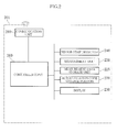
- the sample measuring device 201 is structured as e.g. a self-monitoring blood glucose meter (SMBG meter) used for self-measurement of blood glucose level by the user. As shown in Figs. 1 and 2 , the sample measuring device 201 includes a case 210, a measurement unit 220, a measurement data storage unit 225, a display 230, a sensor strip detector 240, a controller 260, an authentication code storage portion 270 and a communication unit 280. The sample measuring device 201 uses a sensor strip 290 for measurement.
- the sensor strip 290 has a sample application portion 291. To perform measurement with the sample measuring device 201, the sensor strip 290 is inserted into the insertion port 211, and blood of the user is applied to the sample application portion 291.
- the case 210 is made of e.g. resin and defines the outer configuration of the sample measuring device 201.
- the case 210 has the insertion port 211 into which the sensor strip 290 is to be inserted.
- the sensor strip detector 240 is provided behind the insertion port 211 and detects the insertion of the sensor strip 290.
- the sensor strip detector 240 may comprise a mechanical lever (not shown) which pivots when the sensor strip 290 is inserted or apair of detection electrodes (not shown) which are electrically connected to each other when the sensor strip 290 is inserted.
- the measurement unit 220 serves to measure the blood glucose level.
- the measurement unit 220 includes a terminal (not shown) to be electrically connected to the sensor strip 290 to which blood has been applied and measures the blood glucose level by an electrical method.
- the measurement data storage unit 225 comprises e.g. a memory and stores the measurement data obtained by the measurement unit 220.
- the display 230 is an example of the display unit according to the present invention and serves to show measurement data and so on.
- the display 230 comprises a liquid crystal display panel.
- the controller 260 controls each part of the sample measuring device 201 during the measurement operation, and comprises e.g. a CPU.
- the communication unit 280 is an example of the first data transmitter/receiver according to the present invention and serves to transmit and receive data via wireless communication.
- the communication unit 280 performs wireless communication based on the Bluetooth standard.
- the communication unit 280 is capable of performing interactive wireless communication.
- the authentication code storage portion 270 serves to store a passkey (authentication code) necessary for the pairing process (initial authentication process) for establishing a connection between the sample measuring device 201 and the communication device 301.
- a passkey authentication code
- the pairing process initial authentication process
- communication between the paired devices is allowed when the devices are located within a predetermined distance from each other.
- the communication device 301 is e.g. a mobile phone and has a function to receive and store the measurement data transmitted from the sample measuring device 201 and transmit the measurement data to e.g. a server device (not shown) via a public communication network. As shown in Figs. 1 and 3 , the communication device 301 includes a communication unit 310, a communication unit 315, a controller 320, a display 330 and an operation unit 360.
- the communication unit 310 is an example of the second data transmitter/receiver according to the present invention and serves to transmit and receive data via wireless communication.
- the communication unit 310 performs wireless communication based on the Bluetooth standard.
- the communication unit 310 is capable of performing interactive wireless communication.
- the communication unit 315 serves to make access to a mobile phone network via wireless communication.
- the communication device 301 is capable of making access to the mobile phone network and to the Internet via the mobile phone network.
- the controller 320 controls each portion of the communication device 301 during the measurement operation, and comprises e.g. a CPU.
- the display 330 comprises a liquid crystal display panel.
- the operation unit 360 comprises e.g. dial keys or arrow keys.
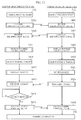
- Fig. 4 is a flowchart showing the operation of the sample measuring device 201.
- the operation of the sample measuring device 201 starts from Step S0.
- Step S0 the display 230 is in a non-display state, and the sample measuring device 201 is in a so-called "power-off state".
- the sensor strip detector 240 is in a state capable of detecting the sensor strip 290.
- the sensor strip detector 240 is designed to detect the sensor strip 290 by an electrical method
- the sensor strip detector 240 is supplied with electric power.
- power supply may be completely shut off.
- This state which corresponds to a so-called "power-off state” and in which the sensor strip detector 240 is ready to detect, is defined as the "standby state" in the present invention.
- Step S1 whether or not the sensor strip 290 is inserted is detected by the sensor strip detector 240.
- an insertion detection signal is transmitted from the sensor strip detector 240 to the controller 260 (see Fig. 2 ).
- the controller 260 starts to supply electric power to the entirety of the sample measuring device 201.
- Step S2 in Fig. 4 the sample measuring device 201 switches to a so-called “power-on state". This state is defined as the "operation state" in the present invention.
- Step S4 whether or not the pairing has been completed is determined.
- the controller 260 receives a status signal of the communication unit 280, and, when it is determined that the pairing has not been completed, causes the pairing process of Step S40 to start.
- the sample measuring device 201 may be designed such that the process proceeds from Step S4 to Step S40 when the sensor strip 290 is once removed and then inserted again by the user.
- Fig. 5 is a flowchart showing the pairing process between the sample measuring device 201 and the communication device 301.
- the pairing process is started in Step S41.
- the pairing process is started in Step S42 by the user's predetermined operation using e.g. the operation unit 360.
- an identification signal is sent out from the communication unit 280 of the sample measuring device 201.
- the identification signal is a signal for allowing the communication device 301 to detect the presence of the sample measuring device 201.
- the controller 320 displays on the display 330 the information contained in the identification signal in Step S422, as shown in Fig. 7 .
- the identification signal contains the name of the sample measuring device 201, which is "SMBG1" in this example, so that "SMBG1" is shown on the display 330 as a possible pairing target device.
- Step S423 shown in Fig. 5 the pairing target device is selected.
- names of a plurality of devices which can be paired with the communication device 301 including "SMBG1" are listed on the display 330 as possible pairing target devices, as shown in Fig. 7 .
- the frame in the display 330 which surrounds one of the names of the devices can be moved up and down by e.g. pressing an arrow key of the operation unit 360.
- the desired device is selected as the pairing target device for the communication device 301.
- "SMBG1" is selected.
- Step S411 When selection of the pairing target device is completed in Step S423 in Fig. 5 , input of the passkey is requested in Step S424 in the communication device 301.
- the passkey is shown in Step S412.
- the passkey stored in the authentication code storage portion 270 is shown on the display 230 of the measuring device 201 as shown in Fig. 8 in Step S412, while a message to prompt the user to input the passkey is shown on the display 330 of the communication device 301 as shown in Fig. 9 in Step S424.
- Step S424 the passkey shown on the display 230 is inputted into the communication device 301 by using e.g. numeric keys of the operation unit 360.
- Step S425 the controller 320 of the communication device 301 sends out the passkey, inputted in Step S424, from the communication unit 310.
- Step S413 the sample measuring device 201 receives the passkey through the communication unit 280.
- Step S414 the passkey received is checked against the passkey stored in the authentication code storage portion 270. When these keys match with each other, the sample measuring device 201 sends out a pairing enabling signal from the communication unit 280 in Step S415.
- the communication device 301 receives the pairing enabling signal through the communication unit 310 in Step S426. After the pairing process is completed in this way in Step S43, the sample measuring device 201 and the communication device 301 can perform interactive wireless communication based on the Bluetooth standard.
- Step S5 in Fig. 4 the blood glucose level is measured by the measurement unit 220.
- the blood glucose level data obtained is stored in the measurement data storage unit225.
- Step S6 the blood glucose level data is transmitted from the communication unit 280 to the communication device 301. This data transmission may be performed automatically when the connection between the sample measuring device 201 and the communication device 301 is established or may be performed by the selection operation by the user.
- Step S7 the sample measuring device 201 is switched to the power-off state in Step S8.
- the user when the user inserts the sensor strip 290 into the sample measuring device 201 to perform measurement, whether or not the pairing has been completed is determined automatically, and if not completed, the pairing process occurs automatically.
- establishment of the connection between the sample measuring device 201 and the communication device 301 does not require any special work by the user.
- the user can transmit measurement data from the sample measuring device 201 to the communication device 301 without worrying about whether or not the connection with the communication device 301 has been established.
- the wireless communication based on the Bluetooth standard for data transmission between the sample measuring device 201 and the communication device 301 when the sample measuring device 201 and the communication device 301 are within a predetermined distance from each other, the data transmission can be started automatically, so that the user does not need to worry about whether or not the connection has been established.
- the sample measuring device 201 switches between the power-on state and the power-off state in accordance with the insertion and removal of the sensor strip 290. This means that switching of the sample measuring device 201 between the power-on state and the power-off state occurs in accordance with the user's intention to perform measurement, just by the operation essential to the measurement, and without the need for any additional operation.
- the measurement and the communication with the communication device 301 can be started easily as the user desires.
- the passkey stored in the authentication code storage portion 270 is shown on the display 230 of the sample measuring device 201, the user does not need to check the manual or the like of the sample measuring device 201 for the passkey. Since the passkey generally consists of a relatively small number of alphanumeric characters, the display 230 does not need to be made large to show the passkey.
- Figs. 10-13 show variations of the sample measuring device and the sample measuring system according to the present invention.
- the elements which are identical or similar to those of the foregoing embodiment are designated by the same reference signs as those used for the foregoing embodiment.
- Fig. 10 shows a variation of the sample measuring device 201.
- the sample measuring device 201 of this variation includes an authentication code print portion 275 instead of the authentication code storage portion 270.
- the authentication code print portion 275 comprises e.g. a label which is attached to the back surface of the case 210 and on which the passkey is printed.
- displaying the passkey in Step S412 is performed not at the display 230 but at the authentication code print portion 275.
- Step S424 the user inputs the passkey printed on the authentication code print portion 275.
- the user can transmit measurement data from the sample measuring device 201 to the communication device 301 without worrying about whether the connection with the communication device 301 has been established. Further, reading the passkey printed on the authentication code print portion 275 such as a label may be easier for some users, such as elderly people, than reading the passkey shown on the display.
- Fig. 11 shows a variation of the pairing process of the sample measuring system 101.
- selection of the pairing target device is performed not only by the communication device 301 but also by the sample measuring device 201.
- the communication device 301 sends out an identification signal in Step S427.
- the identification signal sent out by the communication device 301 is received by the sample measuring device 201 in Step S416, and the name of the communication device 301 is shown in Step S417 on the display 230 of the sample measuring device 201.
- the name "Phone 1" of the communication device 301 is shown.
- Step S418 shown in Fig. 11 the user selects the desired pairing target device by once pulling out and then inserting again the sensor strip 290 when the name of the desired pairing target device ("Phone 1" in this example) is shown on the display 230.
- Fig. 13 shows another way of displaying the names of pairing target devices in Step S417.
- the names of a plurality of possible pairing target devices are shown as a list on the display 230.
- the display 230 there is shown a frame surrounding one of the names of the possible pairing target devices. The frame moves periodically to alternately surround each of the names of the possible pairing target devices.
- Step S418 shown in Fig. 11 the user selects the desired pairing target device by once pulling out and then inserting again the sensor strip 290 when the name of the desired pairing target device ("Phone 1" in this example) is surrounded by the frame.
- the user can transmit measurement data from the sample measuring device 201 to the communication device 301 without worrying about whether the connection with the communication device 301 has been established. Moreover, when there a plurality of devices of the type similar to the communication device 301 are present, pairing the sample measuring device 201 erroneously with an undesired communication device is prevented more reliably.
- sample measuring device and sample measuring system according to the present invention is not limited to the foregoing embodiments.
- the specific structure of each part of the sample measuring device and sample measuring system according to the present invention can be varied in design in many ways.
- the communication device is not limited to a mobile phone, and any devices which can perform wireless communication with the sample measuring device can be used.
- a personal computer designed to transmit and receive data via wireless communication based on the Bluetooth standard may be used as the communication device.
- the sample measuring device according to the present invention is not limited to a SMBG meter.
- the invention is applicable to various devices for performing measurement for which transmission of measurement data to a communication device or collection of measurement data via a communication device is desirable.
- the wireless communication in the present invention is not limited to that based on the Bluetooth standard, and any kind of wireless communication can be used as long as it can realize data transmission and reception between the sample measuring device and the communication device.
Landscapes
- Health & Medical Sciences (AREA)
- Life Sciences & Earth Sciences (AREA)
- Engineering & Computer Science (AREA)
- Biomedical Technology (AREA)
- Physics & Mathematics (AREA)
- Medical Informatics (AREA)
- Public Health (AREA)
- General Health & Medical Sciences (AREA)
- Animal Behavior & Ethology (AREA)
- Veterinary Medicine (AREA)
- Molecular Biology (AREA)
- Surgery (AREA)
- Pathology (AREA)
- Biophysics (AREA)
- Heart & Thoracic Surgery (AREA)
- Computer Networks & Wireless Communication (AREA)
- Emergency Medicine (AREA)
- Optics & Photonics (AREA)
- Business, Economics & Management (AREA)
- General Business, Economics & Management (AREA)
- Epidemiology (AREA)
- Primary Health Care (AREA)
- Automatic Analysis And Handling Materials Therefor (AREA)
- Measurement Of The Respiration, Hearing Ability, Form, And Blood Characteristics Of Living Organisms (AREA)
Abstract
Description
- The present invention relates to a sample measuring device and a sample measuring system.
-
Fig. 14 illustrates an example of sample measuring system (seePatent Document 1, for example). Thesample measuring system 900 shown in the figure comprises asample measuring device 91 and a personal computer 93 (hereinafter referred to as "PC 93"). For instance, thesample measuring device 91 is a self-monitoring blood glucose meter (SMBG meter) which enables users to measure their own blood glucose levels. Measurement by thesample measuring device 91 is performed by inserting asensor strip 92 into thesample measuring device 91 and applying blood to thesensor strip 92. Before or after the measurement, thesample measuring device 91 is connected to the PC 93 via acable 94. The measurement data obtained by thesample measuring device 91 is sent to the PC 93 via thecable 94 and stored in the PC 93. The PC 93 is capable of storing data of a plurality of measurements. The stored measurement data can be checked by e.g. a doctor so that the doctor can provide treatment or medicine suitable for the diabetes symptoms of the user. - However, it is troublesome to connect the
sample measuring device 91 and the PC 93 via thecable 94 at each time of measurement. When the user fails to connect thesample measuring device 91 via thecable 94, the measurement data is not stored in the PC 93. In such a case, it may be difficult for the doctor to provide the user with proper treatment or medicine. - Patent Document 1:
JP-A1-2008-136437 - The present invention has been proposed under the circumstances described above. It is therefore an object of the present invention to provide a sample measuring device and a sample measuring system capable of reducing burdens on the user.
- According to a first aspect of the present invention, there is provided a sample measuring device including a measuring unit for performing measurement with respect to a particular component contained in a sample, a measurement data storage unit for storing measurement data obtained by the measuring unit, a display unit for displaying the measurement data, a sensor strip detector for detecting insertion and removal of a sensor strip to which the sample is applied, and a first data transmitter/receiver for transmitting the measurement data via wireless communication. The first data transmitter/receiver performs initial authentication process for wireless communication after insertion of the sensor strip is detected by the sensor strip detector.
- In a preferred embodiment of the present invention, when insertion of the sensor strip is detected by the sensor strip detector, the sample measuring device switches from a standby state in which the measurement is not possible to an operation state in which the measurement is possible.
- In a preferred embodiment of the present invention, when removal of the sensor strip is detected by the sensor strip detector, the sample measuring device switches from the operation state to the standby state.
- In a preferred embodiment of the present invention, the sample measuring device further includes an authentication code storage portion for storing an authentication code to be used for the initial authentication process, and the authentication code is displayed on the display unit in the initial authentication process.
- In a preferred embodiment of the present invention, the sample measuring device further includes an authentication code print portion in which an authentication code to be used for the initial authentication process is printed.
- In a preferred embodiment of the present invention, the authentication code is a product identification code.
- In a preferred embodiment of the present invention, when the first data transmitter/receiver detects presence of a communication device with which wireless connection can be established, the communication device is identified and indicated on the display unit as a possible connection target device.
- In a preferred embodiment of the present invention, when the first data transmitter/receiver detects presence of a plurality of communication devices with which wireless connection can be established, the communication devices are identified and indicated on the display unit periodically one by one as possible connection target devices.
- In a preferred embodiment of the present invention, the first data transmitter/receiver performs the initial authentication process with respect to one of the plurality of communication devices which is being indicated on the display unit when there is a change in a detection state of the sensor strip detector.
- In a preferred embodiment of the present invention, the change in the detection state of the sensor strip detector is due to removal of the sensor strip from the sample measuring device.
- In a preferred embodiment of the present invention, the change in the detection state of the sensor strip is due to removal and subsequent re-insertion of the sensor strip with respect to the sample measuring device.
- In a preferred embodiment of the present invention, the first data transmitter/receiver performs wireless communication based on Bluetooth (registered trademark) standard.
- In a preferred embodiment of the present invention, the particular component is blood sugar, and the sample measuring device is structured as a self-monitoring blood glucose meter.
- According to a second aspect of the present invention, there is provided a sample measuring system including the sample measuring device provided according to the first aspect of the present invention, and a communication device including a second data transmitter/receiver which is a target for the initial authentication process performed by the first data transmitter/receiver of the sample measuring device.
- In a preferred embodiment of the present invention, the communication device includes an input unit for inputting an authentication code provided by the sample measuring device.
- According to the present invention, when the user inserts the sensor strip into the sample measuring device to perform measurement, whether or not the pairing has been completed is determined automatically, and if not completed, the pairing process occurs automatically. Thus, establishment of the connection between the sample measuring device and the communication device does not require any special work by the user. The user can transmit measurement data from the sample measuring device to the communication device without worrying about whether or not the connection with the communication device has been established.
- Other features and advantages of the present invention will become more apparent from detailed description given below with reference to the accompanying drawings.
-
-
Fig. 1 is a perspective view showing an example of sample measuring device and sample measuring system according to the present invention; -
Fig. 2 is a system block diagram of the example of sample measuring device according to the present invention; -
Fig. 3 is a system block diagram of a communication device used for the example of sample measuring system according to the present invention; -
Fig. 4 is a flowchart showing the operation of the example of sample measuring device according to the present invention; -
Fig. 5 is a flowchart showing the pairing process of the example of sample measuring system according to the present invention; -
Fig. 6 is a front view of the example of sample measuring device, showing the insertion and removal of a sensor strip; -
Fig. 7 is a front view of a display in a step for selecting a pairing target device in the pairing process of the example of sample measuring system according to the present invention; -
Fig. 8 is a front view of a display in a step for showing a passkey in the pairing process of the example of sample measuring system according to the present invention; -
Fig. 9 is a front view of a display in a step for inputting a passkey in the pairing process of the example of sample measuring system according to the present invention; -
Fig. 10 is a rear view of a variation of sample measuring device according to the present invention; -
Fig. 11 is a flowchart showing a variation of pairing process of the sample measuring system according to the present invention; -
Fig. 12 is a front view showing an example of display of the sample measuring device in a step for selecting a pairing target device in the pairing process shown inFig. 11 ; -
Fig. 13 is a front view showing another example of display of the sample measuring device in a step for selecting a pairing target device in the pairing process shown inFig. 11 ; -
Fig. 14 is a perspective view showing an example of conventional sample measuring device and sample measuring system. - Preferred embodiments of the present invention are described below with reference to the accompanying drawings.
-
Fig. 1 shows an example of sample measuring device and sample measuring system according to the present invention. The sample measuringsystem 101 of this embodiment includes asample measuring device 201 and acommunication device 301. - The
sample measuring device 201 is structured as e.g. a self-monitoring blood glucose meter (SMBG meter) used for self-measurement of blood glucose level by the user. As shown inFigs. 1 and2 , thesample measuring device 201 includes acase 210, ameasurement unit 220, a measurementdata storage unit 225, adisplay 230, asensor strip detector 240, acontroller 260, an authenticationcode storage portion 270 and acommunication unit 280. Thesample measuring device 201 uses asensor strip 290 for measurement. Thesensor strip 290 has asample application portion 291. To perform measurement with thesample measuring device 201, thesensor strip 290 is inserted into theinsertion port 211, and blood of the user is applied to thesample application portion 291. - The
case 210 is made of e.g. resin and defines the outer configuration of thesample measuring device 201. Thecase 210 has theinsertion port 211 into which thesensor strip 290 is to be inserted. Thesensor strip detector 240 is provided behind theinsertion port 211 and detects the insertion of thesensor strip 290. For instance, thesensor strip detector 240 may comprise a mechanical lever (not shown) which pivots when thesensor strip 290 is inserted or apair of detection electrodes (not shown) which are electrically connected to each other when thesensor strip 290 is inserted. - The
measurement unit 220 serves to measure the blood glucose level. For instance, themeasurement unit 220 includes a terminal (not shown) to be electrically connected to thesensor strip 290 to which blood has been applied and measures the blood glucose level by an electrical method. The measurementdata storage unit 225 comprises e.g. a memory and stores the measurement data obtained by themeasurement unit 220. Thedisplay 230 is an example of the display unit according to the present invention and serves to show measurement data and so on. For instance, thedisplay 230 comprises a liquid crystal display panel. - The
controller 260 controls each part of thesample measuring device 201 during the measurement operation, and comprises e.g. a CPU. - The
communication unit 280 is an example of the first data transmitter/receiver according to the present invention and serves to transmit and receive data via wireless communication. In this embodiment, thecommunication unit 280 performs wireless communication based on the Bluetooth standard. Thus, thecommunication unit 280 is capable of performing interactive wireless communication. - The authentication
code storage portion 270 serves to store a passkey (authentication code) necessary for the pairing process (initial authentication process) for establishing a connection between thesample measuring device 201 and thecommunication device 301. In the wireless communication based on the Bluetooth standard, after the pairing process is performed once, communication between the paired devices is allowed when the devices are located within a predetermined distance from each other. - The
communication device 301 is e.g. a mobile phone and has a function to receive and store the measurement data transmitted from thesample measuring device 201 and transmit the measurement data to e.g. a server device (not shown) via a public communication network. As shown inFigs. 1 and3 , thecommunication device 301 includes acommunication unit 310, acommunication unit 315, acontroller 320, adisplay 330 and anoperation unit 360. - The
communication unit 310 is an example of the second data transmitter/receiver according to the present invention and serves to transmit and receive data via wireless communication. In this embodiment, thecommunication unit 310 performs wireless communication based on the Bluetooth standard. Thus, thecommunication unit 310 is capable of performing interactive wireless communication. Thecommunication unit 315 serves to make access to a mobile phone network via wireless communication. Thus, thecommunication device 301 is capable of making access to the mobile phone network and to the Internet via the mobile phone network. - The
controller 320 controls each portion of thecommunication device 301 during the measurement operation, and comprises e.g. a CPU. For instance, thedisplay 330 comprises a liquid crystal display panel. Theoperation unit 360 comprises e.g. dial keys or arrow keys. - The operation of the
sample measuring device 201 and thesample measuring system 101 are described below with reference toFigs. 4-9 . -
Fig. 4 is a flowchart showing the operation of thesample measuring device 201. The operation of thesample measuring device 201 starts from Step S0. In Step S0, thedisplay 230 is in a non-display state, and thesample measuring device 201 is in a so-called "power-off state". In this state, however, thesensor strip detector 240 is in a state capable of detecting thesensor strip 290. Specifically, when thesensor strip detector 240 is designed to detect thesensor strip 290 by an electrical method, thesensor strip detector 240 is supplied with electric power. When thesensor strip detector 240 does not require electric power, power supply may be completely shut off. This state, which corresponds to a so-called "power-off state" and in which thesensor strip detector 240 is ready to detect, is defined as the "standby state" in the present invention. - Then, in Step S1, whether or not the
sensor strip 290 is inserted is detected by thesensor strip detector 240. When thesensor strip 290 is inserted as shown inFig. 6 , an insertion detection signal is transmitted from thesensor strip detector 240 to the controller 260 (seeFig. 2 ). Upon receiving the signal, thecontroller 260 starts to supply electric power to the entirety of thesample measuring device 201. Thus, in Step S2 inFig. 4 , thesample measuring device 201 switches to a so-called "power-on state". This state is defined as the "operation state" in the present invention. - Then, in Step S4, whether or not the pairing has been completed is determined. Specifically, the
controller 260 receives a status signal of thecommunication unit 280, and, when it is determined that the pairing has not been completed, causes the pairing process of Step S40 to start. Instead of this automatic proceeding from Step S4 to Step S40 based on the determination by thecontroller 260, thesample measuring device 201 may be designed such that the process proceeds from Step S4 to Step S40 when thesensor strip 290 is once removed and then inserted again by the user. -
Fig. 5 is a flowchart showing the pairing process between thesample measuring device 201 and thecommunication device 301. In thesample measuring device 201, the pairing process is started in Step S41. In thecommunication device 301, the pairing process is started in Step S42 by the user's predetermined operation using e.g. theoperation unit 360. - In Step S411, an identification signal is sent out from the
communication unit 280 of thesample measuring device 201. The identification signal is a signal for allowing thecommunication device 301 to detect the presence of thesample measuring device 201. When thecommunication unit 310 of thecommunication device 301 receives the identification signal in Step S421, thecontroller 320 displays on thedisplay 330 the information contained in the identification signal in Step S422, as shown inFig. 7 . In this embodiment, the identification signal contains the name of thesample measuring device 201, which is "SMBG1" in this example, so that "SMBG1" is shown on thedisplay 330 as a possible pairing target device. - Then, in Step S423 shown in
Fig. 5 , the pairing target device is selected. Specifically, in this embodiment, names of a plurality of devices which can be paired with thecommunication device 301, including "SMBG1", are listed on thedisplay 330 as possible pairing target devices, as shown inFig. 7 . In this instance, the frame in thedisplay 330 which surrounds one of the names of the devices can be moved up and down by e.g. pressing an arrow key of theoperation unit 360. Thus, by positioning the frame around the name of the desired device and then pressing the decision button of theoperation unit 360, the desired device is selected as the pairing target device for thecommunication device 301. In this embodiment, "SMBG1" is selected. - When selection of the pairing target device is completed in Step S423 in
Fig. 5 , input of the passkey is requested in Step S424 in thecommunication device 301. On the other hand, in thesample measuring device 201, when Step S411 is completed, the passkey is shown in Step S412. Specifically, the passkey stored in the authenticationcode storage portion 270 is shown on thedisplay 230 of the measuringdevice 201 as shown inFig. 8 in Step S412, while a message to prompt the user to input the passkey is shown on thedisplay 330 of thecommunication device 301 as shown inFig. 9 in Step S424. In Step S424, the passkey shown on thedisplay 230 is inputted into thecommunication device 301 by using e.g. numeric keys of theoperation unit 360. - Then, in Step S425, the
controller 320 of thecommunication device 301 sends out the passkey, inputted in Step S424, from thecommunication unit 310. In Step S413, thesample measuring device 201 receives the passkey through thecommunication unit 280. Then, in Step S414, the passkey received is checked against the passkey stored in the authenticationcode storage portion 270. When these keys match with each other, thesample measuring device 201 sends out a pairing enabling signal from thecommunication unit 280 in Step S415. Thecommunication device 301 receives the pairing enabling signal through thecommunication unit 310 in Step S426. After the pairing process is completed in this way in Step S43, thesample measuring device 201 and thecommunication device 301 can perform interactive wireless communication based on the Bluetooth standard. - Thereafter, in Step S5 in
Fig. 4 , the blood glucose level is measured by themeasurement unit 220. The blood glucose level data obtained is stored in the measurement data storage unit225. In Step S6, the blood glucose level data is transmitted from thecommunication unit 280 to thecommunication device 301. This data transmission may be performed automatically when the connection between thesample measuring device 201 and thecommunication device 301 is established or may be performed by the selection operation by the user. Thereafter, when removal of thesensor strip 290 is detected by thesensor strip detector 240 in Step S7, thesample measuring device 201 is switched to the power-off state in Step S8. - The advantages of the
sample measuring device 201 and thesample measuring system 101 are described below. - According to the present invention, when the user inserts the
sensor strip 290 into thesample measuring device 201 to perform measurement, whether or not the pairing has been completed is determined automatically, and if not completed, the pairing process occurs automatically. Thus, establishment of the connection between thesample measuring device 201 and thecommunication device 301 does not require any special work by the user. The user can transmit measurement data from thesample measuring device 201 to thecommunication device 301 without worrying about whether or not the connection with thecommunication device 301 has been established. - With the use of the wireless communication based on the Bluetooth standard for data transmission between the
sample measuring device 201 and thecommunication device 301, when thesample measuring device 201 and thecommunication device 301 are within a predetermined distance from each other, the data transmission can be started automatically, so that the user does not need to worry about whether or not the connection has been established. Thesample measuring device 201 switches between the power-on state and the power-off state in accordance with the insertion and removal of thesensor strip 290. This means that switching of thesample measuring device 201 between the power-on state and the power-off state occurs in accordance with the user's intention to perform measurement, just by the operation essential to the measurement, and without the need for any additional operation. Thus, according to thesample measuring device 201, the measurement and the communication with thecommunication device 301 can be started easily as the user desires. - Since the passkey stored in the authentication
code storage portion 270 is shown on thedisplay 230 of thesample measuring device 201, the user does not need to check the manual or the like of thesample measuring device 201 for the passkey. Since the passkey generally consists of a relatively small number of alphanumeric characters, thedisplay 230 does not need to be made large to show the passkey. -
Figs. 10-13 show variations of the sample measuring device and the sample measuring system according to the present invention. In these figures, the elements which are identical or similar to those of the foregoing embodiment are designated by the same reference signs as those used for the foregoing embodiment. -
Fig. 10 shows a variation of thesample measuring device 201. Thesample measuring device 201 of this variation includes an authenticationcode print portion 275 instead of the authenticationcode storage portion 270. The authenticationcode print portion 275 comprises e.g. a label which is attached to the back surface of thecase 210 and on which the passkey is printed. In the pairing process according to this variation, displaying the passkey in Step S412 is performed not at thedisplay 230 but at the authenticationcode print portion 275. In Step S424, the user inputs the passkey printed on the authenticationcode print portion 275. - According to this variation again, the user can transmit measurement data from the
sample measuring device 201 to thecommunication device 301 without worrying about whether the connection with thecommunication device 301 has been established. Further, reading the passkey printed on the authenticationcode print portion 275 such as a label may be easier for some users, such as elderly people, than reading the passkey shown on the display. -
Fig. 11 shows a variation of the pairing process of thesample measuring system 101. In this variation, selection of the pairing target device is performed not only by thecommunication device 301 but also by thesample measuring device 201. Specifically, thecommunication device 301 sends out an identification signal in Step S427. The identification signal sent out by thecommunication device 301 is received by thesample measuring device 201 in Step S416, and the name of thecommunication device 301 is shown in Step S417 on thedisplay 230 of thesample measuring device 201. In this example, the name "Phone 1" of thecommunication device 301 is shown. In this step, when there are other possible target devices which can be paired with thesample measuring device 201, a plurality of device names, including the name "Phone 1", are shown on thedisplay 230 alternately, each for a certain period of time. In Step S418 shown inFig. 11 , the user selects the desired pairing target device by once pulling out and then inserting again thesensor strip 290 when the name of the desired pairing target device ("Phone 1" in this example) is shown on thedisplay 230. -
Fig. 13 shows another way of displaying the names of pairing target devices in Step S417. In this instance, the names of a plurality of possible pairing target devices are shown as a list on thedisplay 230. In thedisplay 230, there is shown a frame surrounding one of the names of the possible pairing target devices. The frame moves periodically to alternately surround each of the names of the possible pairing target devices. In Step S418 shown inFig. 11 , the user selects the desired pairing target device by once pulling out and then inserting again thesensor strip 290 when the name of the desired pairing target device ("Phone 1" in this example) is surrounded by the frame. - According to this variation again, the user can transmit measurement data from the
sample measuring device 201 to thecommunication device 301 without worrying about whether the connection with thecommunication device 301 has been established. Moreover, when there a plurality of devices of the type similar to thecommunication device 301 are present, pairing thesample measuring device 201 erroneously with an undesired communication device is prevented more reliably. - The sample measuring device and sample measuring system according to the present invention is not limited to the foregoing embodiments. The specific structure of each part of the sample measuring device and sample measuring system according to the present invention can be varied in design in many ways.
- The communication device according to the present invention is not limited to a mobile phone, and any devices which can perform wireless communication with the sample measuring device can be used. For instance, a personal computer designed to transmit and receive data via wireless communication based on the Bluetooth standard may be used as the communication device. Moreover, the sample measuring device according to the present invention is not limited to a SMBG meter. The invention is applicable to various devices for performing measurement for which transmission of measurement data to a communication device or collection of measurement data via a communication device is desirable. The wireless communication in the present invention is not limited to that based on the Bluetooth standard, and any kind of wireless communication can be used as long as it can realize data transmission and reception between the sample measuring device and the communication device.
Claims (15)
- A sample measuring device comprising:a measuring unit for performing measurement with respect to a particular component contained in a sample;a measurement data storage unit for storing measurement data obtained by the measuring unit;a display unit for displaying the measurement data;a sensor strip detector for detecting insertion and removal of a sensor strip to which the sample is applied; anda first data transmitter/receiver for transmitting the measurement data via wireless communication;wherein the first data transmitter/receiver performs initial authentication process for wireless communication after insertion of the sensor strip is detected by the sensor strip detector.
- The sample measuring device according to claim 1, wherein, when insertion of the sensor strip is detected by the sensor strip detector, the sample measuring device switches from a standby state in which the measurement is not possible to an operation state in which the measurement is possible.
- The sample measuring device according to claim 2, wherein, when removal of the sensor strip is detected by the sensor strip detector, the sample measuring device switches from the operation state to the standby state.
- The sample measuring device according to any one of claims 1-3, further comprising an authentication code storage portion for storing an authentication code to be used for the initial authentication process, wherein the authentication code is displayed on the display unit in the initial authentication process.
- The sample measuring device according to any one of claims 1-3, further comprising an authentication code print portion in which an authentication code to be used for the initial authentication process is printed.
- The sample measuring device according to claim 5, wherein the authentication code is a product identification code.
- The sample measuring device according to any one of claims 1-6, wherein, when the first data transmitter/receiver detects presence of a communication device with which wireless connection can be established, the communication device is identified and indicated on the display unit as a possible connection target device.
- The sample measuring device according to claim 7, wherein, when the first data transmitter/receiver detects presence of a plurality of communication devices with which wireless connection can be established, the communication devices are identified and indicated on the display unit periodically one by one as possible connection target devices.
- The sample measuring device according to claim 7 or 8, wherein the first data transmitter/receiver performs the initial authentication process with respect to one of the plurality of communication devices which is being indicated on the display unit when there is a change in a detection state of the sensor strip detector.
- The sample measuring device according to claim 9, wherein the change in the detection state of the sensor strip detector is due to removal of the sensor strip from the sample measuring device.
- The sample measuring device according to claim 10, wherein the change in the detection state of the sensor strip is due to removal and subsequent re-insertion of the sensor strip with respect to the sample measuring device.
- The sample measuring device according to any one of claims 1-11, wherein the first data transmitter/receiver performs wireless communication based on Bluetooth (registered trademark) standard.
- The sample measuring device according to any one of claims 1-12, wherein the particular component is blood sugar, and the sample measuring device is structured as a self-monitoring blood glucose meter.
- A sample measuring system comprising:the sample measuring device as set forth in any one of claims 1-13; anda communication device including a second data transmitter/receiver which is a target for the initial authentication process performed by the first data transmitter/receiver of the sample measuring device.
- The sample measuring system according to claim 14, wherein the communication device includes an input unit for inputting an authentication code provided by the sample measuring device.
Applications Claiming Priority (1)
| Application Number | Priority Date | Filing Date | Title |
|---|---|---|---|
| JP2011100409 | 2011-04-28 |
Publications (2)
| Publication Number | Publication Date |
|---|---|
| EP2517620A1 true EP2517620A1 (en) | 2012-10-31 |
| EP2517620B1 EP2517620B1 (en) | 2019-06-26 |
Family
ID=46396979
Family Applications (1)
| Application Number | Title | Priority Date | Filing Date |
|---|---|---|---|
| EP12165998.1A Active EP2517620B1 (en) | 2011-04-28 | 2012-04-27 | Sample measuring device and sample measuring system |
Country Status (4)
| Country | Link |
|---|---|
| US (1) | US8854206B2 (en) |
| EP (1) | EP2517620B1 (en) |
| JP (1) | JP5878424B2 (en) |
| CN (1) | CN102759613B (en) |
Cited By (3)
| Publication number | Priority date | Publication date | Assignee | Title |
|---|---|---|---|---|
| EP2767226A1 (en) * | 2013-02-18 | 2014-08-20 | ARKRAY, Inc. | Medical measurement device and measurement system |
| EP2799004A4 (en) * | 2011-12-26 | 2015-07-01 | Panasonic Healthcare Holdings Co Ltd | MEDICAL MEASURING DEVICE AND MEDICAL MEASURING SYSTEM |
| US9877652B2 (en) | 2013-02-18 | 2018-01-30 | Arkray, Inc. | Medical measurement device and measurement system |
Families Citing this family (9)
| Publication number | Priority date | Publication date | Assignee | Title |
|---|---|---|---|---|
| US10032431B2 (en) | 2013-03-15 | 2018-07-24 | Intel Corporation | Mobile computing device technology and systems and methods utilizing the same |
| US20140322815A1 (en) | 2013-04-26 | 2014-10-30 | Roche Diagnostics Operations, Inc. | Pairing and synchronizing a mobile phone application with a handheld glucose meter |
| CA3205443A1 (en) * | 2013-11-07 | 2015-05-14 | Dexcom, Inc. | Systems and methods for transmitting and continuous monitoring of analyte values |
| JP6365219B2 (en) * | 2014-10-17 | 2018-08-01 | 横河電機株式会社 | Measurement equipment, terminal authentication method |
| AR102615A1 (en) | 2014-11-14 | 2017-03-15 | Bayer Healthcare Llc | ANALYZER ANALYZER |
| AU2016209318A1 (en) * | 2015-01-21 | 2017-04-20 | Dexcom, Inc. | Continuous glucose monitor communication with multiple display devices |
| GB2535471A (en) * | 2015-02-16 | 2016-08-24 | Camlab Ltd | A computer device for acting as a meter |
| DE102020112538A1 (en) * | 2020-05-08 | 2021-12-02 | Netzsch - Gerätebau Gesellschaft mit beschränkter Haftung | Method and system for the analysis of biological material and the use of such a system |
| JP2024047363A (en) | 2022-09-26 | 2024-04-05 | アークレイ株式会社 | MEASUREMENT APPARATUS, MEASUREMENT SYSTEM, MEASUREMENT METHOD, AND MEASUREMENT PROGRAM |
Citations (4)
| Publication number | Priority date | Publication date | Assignee | Title |
|---|---|---|---|---|
| JP2008136437A (en) | 2006-12-04 | 2008-06-19 | Watanabe Kanpodo:Kk | Method for producing soybean ice cream-like food |
| EP2001188A1 (en) * | 2007-06-08 | 2008-12-10 | F.Hoffmann-La Roche Ag | Method for authenticating a medical device and a remote device |
| US20100312082A1 (en) * | 2009-06-04 | 2010-12-09 | Roche Diagnostics Operations, Inc. | Embeddable modules for measuring blood glucose levels |
| US20110063094A1 (en) * | 2007-06-29 | 2011-03-17 | Ulf Meiertoberens | Device and methods for optimizing communications between a medical device and a remote electronic device |
Family Cites Families (13)
| Publication number | Priority date | Publication date | Assignee | Title |
|---|---|---|---|---|
| US7240036B1 (en) * | 2000-07-13 | 2007-07-03 | Gtech Global Services Corporation | Method and system for facilitation of wireless e-commerce transactions |
| JP2002291069A (en) * | 2001-03-28 | 2002-10-04 | Toshiba Corp | Data collection system and data collection method |
| WO2005104933A1 (en) * | 2004-04-28 | 2005-11-10 | Arkray, Inc. | Data processing device, measurement device, and data collection method |
| EP1596538A1 (en) * | 2004-05-10 | 2005-11-16 | Sony Ericsson Mobile Communications AB | Method and device for bluetooth pairing |
| US20050261660A1 (en) * | 2004-05-24 | 2005-11-24 | Choi Soo B | Method for controlling insulin pump using Bluetooth protocol |
| EP1688085A1 (en) * | 2005-02-02 | 2006-08-09 | Disetronic Licensing AG | Ambulatory medical device and method of communication between medical devices |
| JP2008035426A (en) * | 2006-07-31 | 2008-02-14 | Casio Comput Co Ltd | Communication control device, image display device, image generation device, communication control system, communication control method, and program |
| CN101657724B (en) * | 2007-04-27 | 2013-02-06 | 爱科来株式会社 | measuring device |
| US8170609B2 (en) * | 2007-06-20 | 2012-05-01 | Qualcomm Incorporated | Personal virtual assistant providing advice to a user regarding physiological information received about the user |
| CN101303345A (en) * | 2008-06-24 | 2008-11-12 | 暐世生物科技股份有限公司 | Biological sensing system and use method thereof |
| CN101477128B (en) * | 2009-01-23 | 2010-09-08 | 理康互联科技(北京)有限公司 | Blood sugar test system |
| WO2010138817A1 (en) * | 2009-05-29 | 2010-12-02 | Abbott Diabetes Care Inc. | Glucose monitoring system with wireless communications |
| US20100331645A1 (en) * | 2009-06-25 | 2010-12-30 | Roche Diagnostics Operations, Inc. | Methods and systems for wireless communication between a blood glucose meter and a portable communication device |
-
2012
- 2012-04-23 JP JP2012097986A patent/JP5878424B2/en active Active
- 2012-04-27 CN CN201210129971.7A patent/CN102759613B/en active Active
- 2012-04-27 US US13/458,694 patent/US8854206B2/en active Active
- 2012-04-27 EP EP12165998.1A patent/EP2517620B1/en active Active
Patent Citations (4)
| Publication number | Priority date | Publication date | Assignee | Title |
|---|---|---|---|---|
| JP2008136437A (en) | 2006-12-04 | 2008-06-19 | Watanabe Kanpodo:Kk | Method for producing soybean ice cream-like food |
| EP2001188A1 (en) * | 2007-06-08 | 2008-12-10 | F.Hoffmann-La Roche Ag | Method for authenticating a medical device and a remote device |
| US20110063094A1 (en) * | 2007-06-29 | 2011-03-17 | Ulf Meiertoberens | Device and methods for optimizing communications between a medical device and a remote electronic device |
| US20100312082A1 (en) * | 2009-06-04 | 2010-12-09 | Roche Diagnostics Operations, Inc. | Embeddable modules for measuring blood glucose levels |
Cited By (8)
| Publication number | Priority date | Publication date | Assignee | Title |
|---|---|---|---|---|
| EP2799004A4 (en) * | 2011-12-26 | 2015-07-01 | Panasonic Healthcare Holdings Co Ltd | MEDICAL MEASURING DEVICE AND MEDICAL MEASURING SYSTEM |
| US9684763B2 (en) | 2011-12-26 | 2017-06-20 | Panasonic Healthcare Holdings Co., Ltd. | Medical measuring device and medical measuring system |
| US9904764B2 (en) | 2011-12-26 | 2018-02-27 | Panasonic Healthcare Holdings Co., Ltd. | Medical measuring device and medical measuring system |
| US10311969B2 (en) | 2011-12-26 | 2019-06-04 | Phc Holdings Corporation | Medical measuring device and medical measuring system |
| EP2767226A1 (en) * | 2013-02-18 | 2014-08-20 | ARKRAY, Inc. | Medical measurement device and measurement system |
| CN103989456A (en) * | 2013-02-18 | 2014-08-20 | 爱科来株式会社 | Medical measurement device and measurement system |
| CN103989456B (en) * | 2013-02-18 | 2016-08-24 | 爱科来株式会社 | Therapeutic medical determinator and the system of mensuration |
| US9877652B2 (en) | 2013-02-18 | 2018-01-30 | Arkray, Inc. | Medical measurement device and measurement system |
Also Published As
| Publication number | Publication date |
|---|---|
| CN102759613A (en) | 2012-10-31 |
| US20120274443A1 (en) | 2012-11-01 |
| JP2012237748A (en) | 2012-12-06 |
| JP5878424B2 (en) | 2016-03-08 |
| EP2517620B1 (en) | 2019-06-26 |
| US8854206B2 (en) | 2014-10-07 |
| CN102759613B (en) | 2014-09-03 |
Similar Documents
| Publication | Publication Date | Title |
|---|---|---|
| US8854206B2 (en) | Sample measuring device and sample measuring system | |
| US9055900B2 (en) | Specimen measurement device and specimen measurement system | |
| US8895315B2 (en) | Displaying status of a blood glucose measure being transferred wirelessly from a handheld glucose meter | |
| EP2988657B1 (en) | Pairing and synchronizing a mobile phone application with a handheld glucose meter | |
| JP2014209095A (en) | Measurement system | |
| EP1302875B1 (en) | Measurement data processing system | |
| US8895316B2 (en) | Transferring blood glucose measures seamlessly from a handheld glucose meter | |
| KR102260779B1 (en) | Near communication connecting method of continuous glucose monitoring system | |
| EP2967449B1 (en) | Method for transmitting a glucose measure, method for displaying status during a wireless transmission of a glucose measure and handheld glucose meter | |
| US8406521B2 (en) | OCR interface to single result diagnostic interface | |
| EP4537751A1 (en) | Blood sugar measurement device and method | |
| JP2012230521A (en) | Medical management system and medical management system server program | |
| US12178544B2 (en) | Information management system, and pairing method for measurement device and information terminal | |
| CN103356200B (en) | Measuring apparatus and measuring system | |
| CN119547380A (en) | Measuring device, information terminal, and operating procedure of information terminal | |
| US10609231B2 (en) | Image processing apparatus acquiring biological information and associating same with operating state | |
| KR20070041079A (en) | Display color change system of mobile terminal and its method | |
| WO2024252715A1 (en) | Information terminal, control method, and control program | |
| JPH11144179A (en) | Radio meter-reading system |
Legal Events
| Date | Code | Title | Description |
|---|---|---|---|
| PUAI | Public reference made under article 153(3) epc to a published international application that has entered the european phase |
Free format text: ORIGINAL CODE: 0009012 |
|
| AK | Designated contracting states |
Kind code of ref document: A1 Designated state(s): AL AT BE BG CH CY CZ DE DK EE ES FI FR GB GR HR HU IE IS IT LI LT LU LV MC MK MT NL NO PL PT RO RS SE SI SK SM TR |
|
| AX | Request for extension of the european patent |
Extension state: BA ME |
|
| 17P | Request for examination filed |
Effective date: 20130409 |
|
| RAP1 | Party data changed (applicant data changed or rights of an application transferred) |
Owner name: ARKRAY, INC. |
|
| STAA | Information on the status of an ep patent application or granted ep patent |
Free format text: STATUS: EXAMINATION IS IN PROGRESS |
|
| 17Q | First examination report despatched |
Effective date: 20170508 |
|
| GRAP | Despatch of communication of intention to grant a patent |
Free format text: ORIGINAL CODE: EPIDOSNIGR1 |
|
| STAA | Information on the status of an ep patent application or granted ep patent |
Free format text: STATUS: GRANT OF PATENT IS INTENDED |
|
| INTG | Intention to grant announced |
Effective date: 20190212 |
|
| RIN1 | Information on inventor provided before grant (corrected) |
Inventor name: KAI, AKINORI Inventor name: WADA, ATSUSHI |
|
| GRAS | Grant fee paid |
Free format text: ORIGINAL CODE: EPIDOSNIGR3 |
|
| GRAA | (expected) grant |
Free format text: ORIGINAL CODE: 0009210 |
|
| STAA | Information on the status of an ep patent application or granted ep patent |
Free format text: STATUS: THE PATENT HAS BEEN GRANTED |
|
| AK | Designated contracting states |
Kind code of ref document: B1 Designated state(s): AL AT BE BG CH CY CZ DE DK EE ES FI FR GB GR HR HU IE IS IT LI LT LU LV MC MK MT NL NO PL PT RO RS SE SI SK SM TR |
|
| REG | Reference to a national code |
Ref country code: GB Ref legal event code: FG4D |
|
| REG | Reference to a national code |
Ref country code: CH Ref legal event code: EP |
|
| REG | Reference to a national code |
Ref country code: AT Ref legal event code: REF Ref document number: 1147345 Country of ref document: AT Kind code of ref document: T Effective date: 20190715 |
|
| REG | Reference to a national code |
Ref country code: DE Ref legal event code: R096 Ref document number: 602012061345 Country of ref document: DE |
|
| REG | Reference to a national code |
Ref country code: IE Ref legal event code: FG4D |
|
| REG | Reference to a national code |
Ref country code: NL Ref legal event code: MP Effective date: 20190626 |
|
| PG25 | Lapsed in a contracting state [announced via postgrant information from national office to epo] |
Ref country code: SE Free format text: LAPSE BECAUSE OF FAILURE TO SUBMIT A TRANSLATION OF THE DESCRIPTION OR TO PAY THE FEE WITHIN THE PRESCRIBED TIME-LIMIT Effective date: 20190626 Ref country code: HR Free format text: LAPSE BECAUSE OF FAILURE TO SUBMIT A TRANSLATION OF THE DESCRIPTION OR TO PAY THE FEE WITHIN THE PRESCRIBED TIME-LIMIT Effective date: 20190626 Ref country code: LT Free format text: LAPSE BECAUSE OF FAILURE TO SUBMIT A TRANSLATION OF THE DESCRIPTION OR TO PAY THE FEE WITHIN THE PRESCRIBED TIME-LIMIT Effective date: 20190626 Ref country code: NO Free format text: LAPSE BECAUSE OF FAILURE TO SUBMIT A TRANSLATION OF THE DESCRIPTION OR TO PAY THE FEE WITHIN THE PRESCRIBED TIME-LIMIT Effective date: 20190926 Ref country code: FI Free format text: LAPSE BECAUSE OF FAILURE TO SUBMIT A TRANSLATION OF THE DESCRIPTION OR TO PAY THE FEE WITHIN THE PRESCRIBED TIME-LIMIT Effective date: 20190626 Ref country code: AL Free format text: LAPSE BECAUSE OF FAILURE TO SUBMIT A TRANSLATION OF THE DESCRIPTION OR TO PAY THE FEE WITHIN THE PRESCRIBED TIME-LIMIT Effective date: 20190626 |
|
| REG | Reference to a national code |
Ref country code: LT Ref legal event code: MG4D |
|
| PG25 | Lapsed in a contracting state [announced via postgrant information from national office to epo] |
Ref country code: GR Free format text: LAPSE BECAUSE OF FAILURE TO SUBMIT A TRANSLATION OF THE DESCRIPTION OR TO PAY THE FEE WITHIN THE PRESCRIBED TIME-LIMIT Effective date: 20190927 Ref country code: BG Free format text: LAPSE BECAUSE OF FAILURE TO SUBMIT A TRANSLATION OF THE DESCRIPTION OR TO PAY THE FEE WITHIN THE PRESCRIBED TIME-LIMIT Effective date: 20190926 Ref country code: RS Free format text: LAPSE BECAUSE OF FAILURE TO SUBMIT A TRANSLATION OF THE DESCRIPTION OR TO PAY THE FEE WITHIN THE PRESCRIBED TIME-LIMIT Effective date: 20190626 Ref country code: LV Free format text: LAPSE BECAUSE OF FAILURE TO SUBMIT A TRANSLATION OF THE DESCRIPTION OR TO PAY THE FEE WITHIN THE PRESCRIBED TIME-LIMIT Effective date: 20190626 |
|
| REG | Reference to a national code |
Ref country code: AT Ref legal event code: MK05 Ref document number: 1147345 Country of ref document: AT Kind code of ref document: T Effective date: 20190626 |
|
| PG25 | Lapsed in a contracting state [announced via postgrant information from national office to epo] |
Ref country code: NL Free format text: LAPSE BECAUSE OF FAILURE TO SUBMIT A TRANSLATION OF THE DESCRIPTION OR TO PAY THE FEE WITHIN THE PRESCRIBED TIME-LIMIT Effective date: 20190626 Ref country code: SK Free format text: LAPSE BECAUSE OF FAILURE TO SUBMIT A TRANSLATION OF THE DESCRIPTION OR TO PAY THE FEE WITHIN THE PRESCRIBED TIME-LIMIT Effective date: 20190626 Ref country code: PT Free format text: LAPSE BECAUSE OF FAILURE TO SUBMIT A TRANSLATION OF THE DESCRIPTION OR TO PAY THE FEE WITHIN THE PRESCRIBED TIME-LIMIT Effective date: 20191028 Ref country code: RO Free format text: LAPSE BECAUSE OF FAILURE TO SUBMIT A TRANSLATION OF THE DESCRIPTION OR TO PAY THE FEE WITHIN THE PRESCRIBED TIME-LIMIT Effective date: 20190626 Ref country code: CZ Free format text: LAPSE BECAUSE OF FAILURE TO SUBMIT A TRANSLATION OF THE DESCRIPTION OR TO PAY THE FEE WITHIN THE PRESCRIBED TIME-LIMIT Effective date: 20190626 Ref country code: AT Free format text: LAPSE BECAUSE OF FAILURE TO SUBMIT A TRANSLATION OF THE DESCRIPTION OR TO PAY THE FEE WITHIN THE PRESCRIBED TIME-LIMIT Effective date: 20190626 Ref country code: EE Free format text: LAPSE BECAUSE OF FAILURE TO SUBMIT A TRANSLATION OF THE DESCRIPTION OR TO PAY THE FEE WITHIN THE PRESCRIBED TIME-LIMIT Effective date: 20190626 |
|
| PG25 | Lapsed in a contracting state [announced via postgrant information from national office to epo] |
Ref country code: IS Free format text: LAPSE BECAUSE OF FAILURE TO SUBMIT A TRANSLATION OF THE DESCRIPTION OR TO PAY THE FEE WITHIN THE PRESCRIBED TIME-LIMIT Effective date: 20191026 Ref country code: SM Free format text: LAPSE BECAUSE OF FAILURE TO SUBMIT A TRANSLATION OF THE DESCRIPTION OR TO PAY THE FEE WITHIN THE PRESCRIBED TIME-LIMIT Effective date: 20190626 Ref country code: ES Free format text: LAPSE BECAUSE OF FAILURE TO SUBMIT A TRANSLATION OF THE DESCRIPTION OR TO PAY THE FEE WITHIN THE PRESCRIBED TIME-LIMIT Effective date: 20190626 |
|
| PG25 | Lapsed in a contracting state [announced via postgrant information from national office to epo] |
Ref country code: TR Free format text: LAPSE BECAUSE OF FAILURE TO SUBMIT A TRANSLATION OF THE DESCRIPTION OR TO PAY THE FEE WITHIN THE PRESCRIBED TIME-LIMIT Effective date: 20190626 |
|
| PG25 | Lapsed in a contracting state [announced via postgrant information from national office to epo] |
Ref country code: DK Free format text: LAPSE BECAUSE OF FAILURE TO SUBMIT A TRANSLATION OF THE DESCRIPTION OR TO PAY THE FEE WITHIN THE PRESCRIBED TIME-LIMIT Effective date: 20190626 Ref country code: PL Free format text: LAPSE BECAUSE OF FAILURE TO SUBMIT A TRANSLATION OF THE DESCRIPTION OR TO PAY THE FEE WITHIN THE PRESCRIBED TIME-LIMIT Effective date: 20190626 |
|
| PG25 | Lapsed in a contracting state [announced via postgrant information from national office to epo] |
Ref country code: IS Free format text: LAPSE BECAUSE OF FAILURE TO SUBMIT A TRANSLATION OF THE DESCRIPTION OR TO PAY THE FEE WITHIN THE PRESCRIBED TIME-LIMIT Effective date: 20200224 |
|
| REG | Reference to a national code |
Ref country code: DE Ref legal event code: R097 Ref document number: 602012061345 Country of ref document: DE |
|
| PLBE | No opposition filed within time limit |
Free format text: ORIGINAL CODE: 0009261 |
|
| STAA | Information on the status of an ep patent application or granted ep patent |
Free format text: STATUS: NO OPPOSITION FILED WITHIN TIME LIMIT |
|
| PG2D | Information on lapse in contracting state deleted |
Ref country code: IS |
|
| 26N | No opposition filed |
Effective date: 20200603 |
|
| PG25 | Lapsed in a contracting state [announced via postgrant information from national office to epo] |
Ref country code: SI Free format text: LAPSE BECAUSE OF FAILURE TO SUBMIT A TRANSLATION OF THE DESCRIPTION OR TO PAY THE FEE WITHIN THE PRESCRIBED TIME-LIMIT Effective date: 20190626 |
|
| PG25 | Lapsed in a contracting state [announced via postgrant information from national office to epo] |
Ref country code: MC Free format text: LAPSE BECAUSE OF FAILURE TO SUBMIT A TRANSLATION OF THE DESCRIPTION OR TO PAY THE FEE WITHIN THE PRESCRIBED TIME-LIMIT Effective date: 20190626 |
|
| REG | Reference to a national code |
Ref country code: CH Ref legal event code: PL |
|
| PG25 | Lapsed in a contracting state [announced via postgrant information from national office to epo] |
Ref country code: LI Free format text: LAPSE BECAUSE OF NON-PAYMENT OF DUE FEES Effective date: 20200430 Ref country code: LU Free format text: LAPSE BECAUSE OF NON-PAYMENT OF DUE FEES Effective date: 20200427 Ref country code: CH Free format text: LAPSE BECAUSE OF NON-PAYMENT OF DUE FEES Effective date: 20200430 |
|
| REG | Reference to a national code |
Ref country code: BE Ref legal event code: MM Effective date: 20200430 |
|
| PG25 | Lapsed in a contracting state [announced via postgrant information from national office to epo] |
Ref country code: BE Free format text: LAPSE BECAUSE OF NON-PAYMENT OF DUE FEES Effective date: 20200430 |
|
| PG25 | Lapsed in a contracting state [announced via postgrant information from national office to epo] |
Ref country code: IE Free format text: LAPSE BECAUSE OF NON-PAYMENT OF DUE FEES Effective date: 20200427 |
|
| PG25 | Lapsed in a contracting state [announced via postgrant information from national office to epo] |
Ref country code: MT Free format text: LAPSE BECAUSE OF FAILURE TO SUBMIT A TRANSLATION OF THE DESCRIPTION OR TO PAY THE FEE WITHIN THE PRESCRIBED TIME-LIMIT Effective date: 20190626 Ref country code: CY Free format text: LAPSE BECAUSE OF FAILURE TO SUBMIT A TRANSLATION OF THE DESCRIPTION OR TO PAY THE FEE WITHIN THE PRESCRIBED TIME-LIMIT Effective date: 20190626 |
|
| PG25 | Lapsed in a contracting state [announced via postgrant information from national office to epo] |
Ref country code: MK Free format text: LAPSE BECAUSE OF FAILURE TO SUBMIT A TRANSLATION OF THE DESCRIPTION OR TO PAY THE FEE WITHIN THE PRESCRIBED TIME-LIMIT Effective date: 20190626 |
|
| PGFP | Annual fee paid to national office [announced via postgrant information from national office to epo] |
Ref country code: DE Payment date: 20250422 Year of fee payment: 14 |
|
| PGFP | Annual fee paid to national office [announced via postgrant information from national office to epo] |
Ref country code: GB Payment date: 20250423 Year of fee payment: 14 |
|
| PGFP | Annual fee paid to national office [announced via postgrant information from national office to epo] |
Ref country code: IT Payment date: 20250424 Year of fee payment: 14 |
|
| PGFP | Annual fee paid to national office [announced via postgrant information from national office to epo] |
Ref country code: FR Payment date: 20250425 Year of fee payment: 14 |