EP2517532B1 - Dispositif d'assemblage par collage utilisant un chauffage par induction - Google Patents
Dispositif d'assemblage par collage utilisant un chauffage par induction Download PDFInfo
- Publication number
- EP2517532B1 EP2517532B1 EP10796428.0A EP10796428A EP2517532B1 EP 2517532 B1 EP2517532 B1 EP 2517532B1 EP 10796428 A EP10796428 A EP 10796428A EP 2517532 B1 EP2517532 B1 EP 2517532B1
- Authority
- EP
- European Patent Office
- Prior art keywords
- induction coil
- applicator
- induction
- coil
- assembly
- Prior art date
- Legal status (The legal status is an assumption and is not a legal conclusion. Google has not performed a legal analysis and makes no representation as to the accuracy of the status listed.)
- Not-in-force
Links
- 230000006698 induction Effects 0.000 title claims description 66
- 238000010438 heat treatment Methods 0.000 title description 22
- 239000000853 adhesive Substances 0.000 claims description 38
- 230000001070 adhesive effect Effects 0.000 claims description 38
- 239000002131 composite material Substances 0.000 claims description 13
- 238000004804 winding Methods 0.000 claims description 11
- 239000000463 material Substances 0.000 claims description 9
- 239000004020 conductor Substances 0.000 claims description 6
- 229920001187 thermosetting polymer Polymers 0.000 claims description 6
- 238000004026 adhesive bonding Methods 0.000 claims description 4
- 239000011159 matrix material Substances 0.000 claims description 4
- RYGMFSIKBFXOCR-UHFFFAOYSA-N Copper Chemical compound [Cu] RYGMFSIKBFXOCR-UHFFFAOYSA-N 0.000 claims description 3
- 230000015556 catabolic process Effects 0.000 claims description 3
- 229910052802 copper Inorganic materials 0.000 claims description 3
- 239000010949 copper Substances 0.000 claims description 3
- 238000006731 degradation reaction Methods 0.000 claims description 3
- 238000009529 body temperature measurement Methods 0.000 claims description 2
- 239000002826 coolant Substances 0.000 claims description 2
- 239000012777 electrically insulating material Substances 0.000 claims description 2
- 230000000593 degrading effect Effects 0.000 claims 1
- 239000003990 capacitor Substances 0.000 description 10
- 229920000049 Carbon (fiber) Polymers 0.000 description 6
- 239000004917 carbon fiber Substances 0.000 description 6
- 238000004132 cross linking Methods 0.000 description 6
- 239000012790 adhesive layer Substances 0.000 description 4
- 239000002184 metal Substances 0.000 description 4
- 229910052751 metal Inorganic materials 0.000 description 4
- 230000002787 reinforcement Effects 0.000 description 4
- 230000001939 inductive effect Effects 0.000 description 3
- 230000035515 penetration Effects 0.000 description 3
- 239000000523 sample Substances 0.000 description 3
- 238000007725 thermal activation Methods 0.000 description 3
- 230000008901 benefit Effects 0.000 description 2
- 238000006243 chemical reaction Methods 0.000 description 2
- 230000005670 electromagnetic radiation Effects 0.000 description 2
- 239000000835 fiber Substances 0.000 description 2
- 239000010410 layer Substances 0.000 description 2
- 238000000034 method Methods 0.000 description 2
- 239000004593 Epoxy Substances 0.000 description 1
- 239000000919 ceramic Substances 0.000 description 1
- 239000000470 constituent Substances 0.000 description 1
- 238000001816 cooling Methods 0.000 description 1
- 239000012809 cooling fluid Substances 0.000 description 1
- 238000010586 diagram Methods 0.000 description 1
- 238000009826 distribution Methods 0.000 description 1
- 230000009977 dual effect Effects 0.000 description 1
- 230000000694 effects Effects 0.000 description 1
- 239000000806 elastomer Substances 0.000 description 1
- 229920001971 elastomer Polymers 0.000 description 1
- 230000005672 electromagnetic field Effects 0.000 description 1
- 150000002118 epoxides Chemical class 0.000 description 1
- 239000003822 epoxy resin Substances 0.000 description 1
- 230000004907 flux Effects 0.000 description 1
- 230000004927 fusion Effects 0.000 description 1
- 230000005484 gravity Effects 0.000 description 1
- 239000013529 heat transfer fluid Substances 0.000 description 1
- 230000010354 integration Effects 0.000 description 1
- 238000005259 measurement Methods 0.000 description 1
- 239000007769 metal material Substances 0.000 description 1
- 238000002156 mixing Methods 0.000 description 1
- 230000003287 optical effect Effects 0.000 description 1
- 239000013307 optical fiber Substances 0.000 description 1
- 239000002245 particle Substances 0.000 description 1
- 239000008188 pellet Substances 0.000 description 1
- 239000004033 plastic Substances 0.000 description 1
- 229920000647 polyepoxide Polymers 0.000 description 1
- 238000006116 polymerization reaction Methods 0.000 description 1
- 230000001681 protective effect Effects 0.000 description 1
- 230000005855 radiation Effects 0.000 description 1
- 230000003014 reinforcing effect Effects 0.000 description 1
- 229920005989 resin Polymers 0.000 description 1
- 239000011347 resin Substances 0.000 description 1
- 238000005096 rolling process Methods 0.000 description 1
- 238000006467 substitution reaction Methods 0.000 description 1
- 239000000725 suspension Substances 0.000 description 1
- 239000012815 thermoplastic material Substances 0.000 description 1
- XLYOFNOQVPJJNP-UHFFFAOYSA-N water Substances O XLYOFNOQVPJJNP-UHFFFAOYSA-N 0.000 description 1
Images


Classifications
-
- H—ELECTRICITY
- H05—ELECTRIC TECHNIQUES NOT OTHERWISE PROVIDED FOR
- H05B—ELECTRIC HEATING; ELECTRIC LIGHT SOURCES NOT OTHERWISE PROVIDED FOR; CIRCUIT ARRANGEMENTS FOR ELECTRIC LIGHT SOURCES, IN GENERAL
- H05B6/00—Heating by electric, magnetic or electromagnetic fields
- H05B6/02—Induction heating
- H05B6/10—Induction heating apparatus, other than furnaces, for specific applications
- H05B6/14—Tools, e.g. nozzles, rollers, calenders
-
- B—PERFORMING OPERATIONS; TRANSPORTING
- B29—WORKING OF PLASTICS; WORKING OF SUBSTANCES IN A PLASTIC STATE IN GENERAL
- B29C—SHAPING OR JOINING OF PLASTICS; SHAPING OF MATERIAL IN A PLASTIC STATE, NOT OTHERWISE PROVIDED FOR; AFTER-TREATMENT OF THE SHAPED PRODUCTS, e.g. REPAIRING
- B29C65/00—Joining or sealing of preformed parts, e.g. welding of plastics materials; Apparatus therefor
- B29C65/02—Joining or sealing of preformed parts, e.g. welding of plastics materials; Apparatus therefor by heating, with or without pressure
- B29C65/34—Joining or sealing of preformed parts, e.g. welding of plastics materials; Apparatus therefor by heating, with or without pressure using heated elements which remain in the joint, e.g. "verlorenes Schweisselement"
- B29C65/36—Joining or sealing of preformed parts, e.g. welding of plastics materials; Apparatus therefor by heating, with or without pressure using heated elements which remain in the joint, e.g. "verlorenes Schweisselement" heated by induction
- B29C65/3672—Joining or sealing of preformed parts, e.g. welding of plastics materials; Apparatus therefor by heating, with or without pressure using heated elements which remain in the joint, e.g. "verlorenes Schweisselement" heated by induction characterised by the composition of the elements heated by induction which remain in the joint
- B29C65/3676—Joining or sealing of preformed parts, e.g. welding of plastics materials; Apparatus therefor by heating, with or without pressure using heated elements which remain in the joint, e.g. "verlorenes Schweisselement" heated by induction characterised by the composition of the elements heated by induction which remain in the joint being metallic
-
- B—PERFORMING OPERATIONS; TRANSPORTING
- B29—WORKING OF PLASTICS; WORKING OF SUBSTANCES IN A PLASTIC STATE IN GENERAL
- B29C—SHAPING OR JOINING OF PLASTICS; SHAPING OF MATERIAL IN A PLASTIC STATE, NOT OTHERWISE PROVIDED FOR; AFTER-TREATMENT OF THE SHAPED PRODUCTS, e.g. REPAIRING
- B29C65/00—Joining or sealing of preformed parts, e.g. welding of plastics materials; Apparatus therefor
- B29C65/02—Joining or sealing of preformed parts, e.g. welding of plastics materials; Apparatus therefor by heating, with or without pressure
- B29C65/34—Joining or sealing of preformed parts, e.g. welding of plastics materials; Apparatus therefor by heating, with or without pressure using heated elements which remain in the joint, e.g. "verlorenes Schweisselement"
- B29C65/36—Joining or sealing of preformed parts, e.g. welding of plastics materials; Apparatus therefor by heating, with or without pressure using heated elements which remain in the joint, e.g. "verlorenes Schweisselement" heated by induction
- B29C65/3672—Joining or sealing of preformed parts, e.g. welding of plastics materials; Apparatus therefor by heating, with or without pressure using heated elements which remain in the joint, e.g. "verlorenes Schweisselement" heated by induction characterised by the composition of the elements heated by induction which remain in the joint
- B29C65/3684—Joining or sealing of preformed parts, e.g. welding of plastics materials; Apparatus therefor by heating, with or without pressure using heated elements which remain in the joint, e.g. "verlorenes Schweisselement" heated by induction characterised by the composition of the elements heated by induction which remain in the joint being non-metallic
-
- B—PERFORMING OPERATIONS; TRANSPORTING
- B29—WORKING OF PLASTICS; WORKING OF SUBSTANCES IN A PLASTIC STATE IN GENERAL
- B29C—SHAPING OR JOINING OF PLASTICS; SHAPING OF MATERIAL IN A PLASTIC STATE, NOT OTHERWISE PROVIDED FOR; AFTER-TREATMENT OF THE SHAPED PRODUCTS, e.g. REPAIRING
- B29C65/00—Joining or sealing of preformed parts, e.g. welding of plastics materials; Apparatus therefor
- B29C65/48—Joining or sealing of preformed parts, e.g. welding of plastics materials; Apparatus therefor using adhesives, i.e. using supplementary joining material; solvent bonding
-
- B—PERFORMING OPERATIONS; TRANSPORTING
- B29—WORKING OF PLASTICS; WORKING OF SUBSTANCES IN A PLASTIC STATE IN GENERAL
- B29C—SHAPING OR JOINING OF PLASTICS; SHAPING OF MATERIAL IN A PLASTIC STATE, NOT OTHERWISE PROVIDED FOR; AFTER-TREATMENT OF THE SHAPED PRODUCTS, e.g. REPAIRING
- B29C65/00—Joining or sealing of preformed parts, e.g. welding of plastics materials; Apparatus therefor
- B29C65/48—Joining or sealing of preformed parts, e.g. welding of plastics materials; Apparatus therefor using adhesives, i.e. using supplementary joining material; solvent bonding
- B29C65/4805—Joining or sealing of preformed parts, e.g. welding of plastics materials; Apparatus therefor using adhesives, i.e. using supplementary joining material; solvent bonding characterised by the type of adhesives
- B29C65/483—Reactive adhesives, e.g. chemically curing adhesives
- B29C65/4835—Heat curing adhesives
-
- B—PERFORMING OPERATIONS; TRANSPORTING
- B29—WORKING OF PLASTICS; WORKING OF SUBSTANCES IN A PLASTIC STATE IN GENERAL
- B29C—SHAPING OR JOINING OF PLASTICS; SHAPING OF MATERIAL IN A PLASTIC STATE, NOT OTHERWISE PROVIDED FOR; AFTER-TREATMENT OF THE SHAPED PRODUCTS, e.g. REPAIRING
- B29C66/00—General aspects of processes or apparatus for joining preformed parts
- B29C66/01—General aspects dealing with the joint area or with the area to be joined
- B29C66/05—Particular design of joint configurations
- B29C66/10—Particular design of joint configurations particular design of the joint cross-sections
- B29C66/11—Joint cross-sections comprising a single joint-segment, i.e. one of the parts to be joined comprising a single joint-segment in the joint cross-section
- B29C66/112—Single lapped joints
- B29C66/1122—Single lap to lap joints, i.e. overlap joints
-
- B—PERFORMING OPERATIONS; TRANSPORTING
- B29—WORKING OF PLASTICS; WORKING OF SUBSTANCES IN A PLASTIC STATE IN GENERAL
- B29C—SHAPING OR JOINING OF PLASTICS; SHAPING OF MATERIAL IN A PLASTIC STATE, NOT OTHERWISE PROVIDED FOR; AFTER-TREATMENT OF THE SHAPED PRODUCTS, e.g. REPAIRING
- B29C66/00—General aspects of processes or apparatus for joining preformed parts
- B29C66/01—General aspects dealing with the joint area or with the area to be joined
- B29C66/05—Particular design of joint configurations
- B29C66/20—Particular design of joint configurations particular design of the joint lines, e.g. of the weld lines
- B29C66/21—Particular design of joint configurations particular design of the joint lines, e.g. of the weld lines said joint lines being formed by a single dot or dash or by several dots or dashes, i.e. spot joining or spot welding
-
- B—PERFORMING OPERATIONS; TRANSPORTING
- B29—WORKING OF PLASTICS; WORKING OF SUBSTANCES IN A PLASTIC STATE IN GENERAL
- B29C—SHAPING OR JOINING OF PLASTICS; SHAPING OF MATERIAL IN A PLASTIC STATE, NOT OTHERWISE PROVIDED FOR; AFTER-TREATMENT OF THE SHAPED PRODUCTS, e.g. REPAIRING
- B29C66/00—General aspects of processes or apparatus for joining preformed parts
- B29C66/01—General aspects dealing with the joint area or with the area to be joined
- B29C66/347—General aspects dealing with the joint area or with the area to be joined using particular temperature distributions or gradients; using particular heat distributions or gradients
- B29C66/3474—General aspects dealing with the joint area or with the area to be joined using particular temperature distributions or gradients; using particular heat distributions or gradients perpendicular to the plane of the joint
-
- B—PERFORMING OPERATIONS; TRANSPORTING
- B29—WORKING OF PLASTICS; WORKING OF SUBSTANCES IN A PLASTIC STATE IN GENERAL
- B29C—SHAPING OR JOINING OF PLASTICS; SHAPING OF MATERIAL IN A PLASTIC STATE, NOT OTHERWISE PROVIDED FOR; AFTER-TREATMENT OF THE SHAPED PRODUCTS, e.g. REPAIRING
- B29C66/00—General aspects of processes or apparatus for joining preformed parts
- B29C66/40—General aspects of joining substantially flat articles, e.g. plates, sheets or web-like materials; Making flat seams in tubular or hollow articles; Joining single elements to substantially flat surfaces
- B29C66/41—Joining substantially flat articles ; Making flat seams in tubular or hollow articles
- B29C66/45—Joining of substantially the whole surface of the articles
-
- B—PERFORMING OPERATIONS; TRANSPORTING
- B29—WORKING OF PLASTICS; WORKING OF SUBSTANCES IN A PLASTIC STATE IN GENERAL
- B29C—SHAPING OR JOINING OF PLASTICS; SHAPING OF MATERIAL IN A PLASTIC STATE, NOT OTHERWISE PROVIDED FOR; AFTER-TREATMENT OF THE SHAPED PRODUCTS, e.g. REPAIRING
- B29C66/00—General aspects of processes or apparatus for joining preformed parts
- B29C66/90—Measuring or controlling the joining process
- B29C66/91—Measuring or controlling the joining process by measuring or controlling the temperature, the heat or the thermal flux
- B29C66/912—Measuring or controlling the joining process by measuring or controlling the temperature, the heat or the thermal flux by measuring the temperature, the heat or the thermal flux
- B29C66/9121—Measuring or controlling the joining process by measuring or controlling the temperature, the heat or the thermal flux by measuring the temperature, the heat or the thermal flux by measuring the temperature
- B29C66/91211—Measuring or controlling the joining process by measuring or controlling the temperature, the heat or the thermal flux by measuring the temperature, the heat or the thermal flux by measuring the temperature with special temperature measurement means or methods
- B29C66/91212—Measuring or controlling the joining process by measuring or controlling the temperature, the heat or the thermal flux by measuring the temperature, the heat or the thermal flux by measuring the temperature with special temperature measurement means or methods involving measurement means being part of the welding jaws, e.g. integrated in the welding jaws
-
- B—PERFORMING OPERATIONS; TRANSPORTING
- B29—WORKING OF PLASTICS; WORKING OF SUBSTANCES IN A PLASTIC STATE IN GENERAL
- B29C—SHAPING OR JOINING OF PLASTICS; SHAPING OF MATERIAL IN A PLASTIC STATE, NOT OTHERWISE PROVIDED FOR; AFTER-TREATMENT OF THE SHAPED PRODUCTS, e.g. REPAIRING
- B29C66/00—General aspects of processes or apparatus for joining preformed parts
- B29C66/90—Measuring or controlling the joining process
- B29C66/91—Measuring or controlling the joining process by measuring or controlling the temperature, the heat or the thermal flux
- B29C66/912—Measuring or controlling the joining process by measuring or controlling the temperature, the heat or the thermal flux by measuring the temperature, the heat or the thermal flux
- B29C66/9121—Measuring or controlling the joining process by measuring or controlling the temperature, the heat or the thermal flux by measuring the temperature, the heat or the thermal flux by measuring the temperature
- B29C66/91211—Measuring or controlling the joining process by measuring or controlling the temperature, the heat or the thermal flux by measuring the temperature, the heat or the thermal flux by measuring the temperature with special temperature measurement means or methods
- B29C66/91216—Measuring or controlling the joining process by measuring or controlling the temperature, the heat or the thermal flux by measuring the temperature, the heat or the thermal flux by measuring the temperature with special temperature measurement means or methods enabling contactless temperature measurements, e.g. using a pyrometer
-
- B—PERFORMING OPERATIONS; TRANSPORTING
- B29—WORKING OF PLASTICS; WORKING OF SUBSTANCES IN A PLASTIC STATE IN GENERAL
- B29C—SHAPING OR JOINING OF PLASTICS; SHAPING OF MATERIAL IN A PLASTIC STATE, NOT OTHERWISE PROVIDED FOR; AFTER-TREATMENT OF THE SHAPED PRODUCTS, e.g. REPAIRING
- B29C66/00—General aspects of processes or apparatus for joining preformed parts
- B29C66/90—Measuring or controlling the joining process
- B29C66/91—Measuring or controlling the joining process by measuring or controlling the temperature, the heat or the thermal flux
- B29C66/912—Measuring or controlling the joining process by measuring or controlling the temperature, the heat or the thermal flux by measuring the temperature, the heat or the thermal flux
- B29C66/9121—Measuring or controlling the joining process by measuring or controlling the temperature, the heat or the thermal flux by measuring the temperature, the heat or the thermal flux by measuring the temperature
- B29C66/91221—Measuring or controlling the joining process by measuring or controlling the temperature, the heat or the thermal flux by measuring the temperature, the heat or the thermal flux by measuring the temperature of the parts to be joined
-
- B—PERFORMING OPERATIONS; TRANSPORTING
- B29—WORKING OF PLASTICS; WORKING OF SUBSTANCES IN A PLASTIC STATE IN GENERAL
- B29C—SHAPING OR JOINING OF PLASTICS; SHAPING OF MATERIAL IN A PLASTIC STATE, NOT OTHERWISE PROVIDED FOR; AFTER-TREATMENT OF THE SHAPED PRODUCTS, e.g. REPAIRING
- B29C66/00—General aspects of processes or apparatus for joining preformed parts
- B29C66/90—Measuring or controlling the joining process
- B29C66/91—Measuring or controlling the joining process by measuring or controlling the temperature, the heat or the thermal flux
- B29C66/914—Measuring or controlling the joining process by measuring or controlling the temperature, the heat or the thermal flux by controlling or regulating the temperature, the heat or the thermal flux
- B29C66/9141—Measuring or controlling the joining process by measuring or controlling the temperature, the heat or the thermal flux by controlling or regulating the temperature, the heat or the thermal flux by controlling or regulating the temperature
- B29C66/91411—Measuring or controlling the joining process by measuring or controlling the temperature, the heat or the thermal flux by controlling or regulating the temperature, the heat or the thermal flux by controlling or regulating the temperature of the parts to be joined, e.g. the joining process taking the temperature of the parts to be joined into account
-
- B—PERFORMING OPERATIONS; TRANSPORTING
- B29—WORKING OF PLASTICS; WORKING OF SUBSTANCES IN A PLASTIC STATE IN GENERAL
- B29C—SHAPING OR JOINING OF PLASTICS; SHAPING OF MATERIAL IN A PLASTIC STATE, NOT OTHERWISE PROVIDED FOR; AFTER-TREATMENT OF THE SHAPED PRODUCTS, e.g. REPAIRING
- B29C66/00—General aspects of processes or apparatus for joining preformed parts
- B29C66/90—Measuring or controlling the joining process
- B29C66/91—Measuring or controlling the joining process by measuring or controlling the temperature, the heat or the thermal flux
- B29C66/914—Measuring or controlling the joining process by measuring or controlling the temperature, the heat or the thermal flux by controlling or regulating the temperature, the heat or the thermal flux
- B29C66/9161—Measuring or controlling the joining process by measuring or controlling the temperature, the heat or the thermal flux by controlling or regulating the temperature, the heat or the thermal flux by controlling or regulating the heat or the thermal flux, i.e. the heat flux
- B29C66/91651—Measuring or controlling the joining process by measuring or controlling the temperature, the heat or the thermal flux by controlling or regulating the temperature, the heat or the thermal flux by controlling or regulating the heat or the thermal flux, i.e. the heat flux by controlling or regulating the heat generated by Joule heating or induction heating
-
- B—PERFORMING OPERATIONS; TRANSPORTING
- B29—WORKING OF PLASTICS; WORKING OF SUBSTANCES IN A PLASTIC STATE IN GENERAL
- B29C—SHAPING OR JOINING OF PLASTICS; SHAPING OF MATERIAL IN A PLASTIC STATE, NOT OTHERWISE PROVIDED FOR; AFTER-TREATMENT OF THE SHAPED PRODUCTS, e.g. REPAIRING
- B29C65/00—Joining or sealing of preformed parts, e.g. welding of plastics materials; Apparatus therefor
- B29C65/02—Joining or sealing of preformed parts, e.g. welding of plastics materials; Apparatus therefor by heating, with or without pressure
- B29C65/34—Joining or sealing of preformed parts, e.g. welding of plastics materials; Apparatus therefor by heating, with or without pressure using heated elements which remain in the joint, e.g. "verlorenes Schweisselement"
- B29C65/36—Joining or sealing of preformed parts, e.g. welding of plastics materials; Apparatus therefor by heating, with or without pressure using heated elements which remain in the joint, e.g. "verlorenes Schweisselement" heated by induction
- B29C65/3604—Joining or sealing of preformed parts, e.g. welding of plastics materials; Apparatus therefor by heating, with or without pressure using heated elements which remain in the joint, e.g. "verlorenes Schweisselement" heated by induction characterised by the type of elements heated by induction which remain in the joint
- B29C65/3608—Joining or sealing of preformed parts, e.g. welding of plastics materials; Apparatus therefor by heating, with or without pressure using heated elements which remain in the joint, e.g. "verlorenes Schweisselement" heated by induction characterised by the type of elements heated by induction which remain in the joint comprising single particles, e.g. fillers or discontinuous fibre-reinforcements
- B29C65/3616—Joining or sealing of preformed parts, e.g. welding of plastics materials; Apparatus therefor by heating, with or without pressure using heated elements which remain in the joint, e.g. "verlorenes Schweisselement" heated by induction characterised by the type of elements heated by induction which remain in the joint comprising single particles, e.g. fillers or discontinuous fibre-reinforcements comprising discontinuous fibre-reinforcements
-
- B—PERFORMING OPERATIONS; TRANSPORTING
- B29—WORKING OF PLASTICS; WORKING OF SUBSTANCES IN A PLASTIC STATE IN GENERAL
- B29C—SHAPING OR JOINING OF PLASTICS; SHAPING OF MATERIAL IN A PLASTIC STATE, NOT OTHERWISE PROVIDED FOR; AFTER-TREATMENT OF THE SHAPED PRODUCTS, e.g. REPAIRING
- B29C65/00—Joining or sealing of preformed parts, e.g. welding of plastics materials; Apparatus therefor
- B29C65/02—Joining or sealing of preformed parts, e.g. welding of plastics materials; Apparatus therefor by heating, with or without pressure
- B29C65/34—Joining or sealing of preformed parts, e.g. welding of plastics materials; Apparatus therefor by heating, with or without pressure using heated elements which remain in the joint, e.g. "verlorenes Schweisselement"
- B29C65/36—Joining or sealing of preformed parts, e.g. welding of plastics materials; Apparatus therefor by heating, with or without pressure using heated elements which remain in the joint, e.g. "verlorenes Schweisselement" heated by induction
- B29C65/3604—Joining or sealing of preformed parts, e.g. welding of plastics materials; Apparatus therefor by heating, with or without pressure using heated elements which remain in the joint, e.g. "verlorenes Schweisselement" heated by induction characterised by the type of elements heated by induction which remain in the joint
- B29C65/3656—Joining or sealing of preformed parts, e.g. welding of plastics materials; Apparatus therefor by heating, with or without pressure using heated elements which remain in the joint, e.g. "verlorenes Schweisselement" heated by induction characterised by the type of elements heated by induction which remain in the joint being a layer of a multilayer part to be joined, e.g. for joining plastic-metal laminates
-
- B—PERFORMING OPERATIONS; TRANSPORTING
- B29—WORKING OF PLASTICS; WORKING OF SUBSTANCES IN A PLASTIC STATE IN GENERAL
- B29C—SHAPING OR JOINING OF PLASTICS; SHAPING OF MATERIAL IN A PLASTIC STATE, NOT OTHERWISE PROVIDED FOR; AFTER-TREATMENT OF THE SHAPED PRODUCTS, e.g. REPAIRING
- B29C65/00—Joining or sealing of preformed parts, e.g. welding of plastics materials; Apparatus therefor
- B29C65/48—Joining or sealing of preformed parts, e.g. welding of plastics materials; Apparatus therefor using adhesives, i.e. using supplementary joining material; solvent bonding
- B29C65/4805—Joining or sealing of preformed parts, e.g. welding of plastics materials; Apparatus therefor using adhesives, i.e. using supplementary joining material; solvent bonding characterised by the type of adhesives
- B29C65/483—Reactive adhesives, e.g. chemically curing adhesives
- B29C65/4845—Radiation curing adhesives, e.g. UV light curing adhesives
-
- B—PERFORMING OPERATIONS; TRANSPORTING
- B29—WORKING OF PLASTICS; WORKING OF SUBSTANCES IN A PLASTIC STATE IN GENERAL
- B29C—SHAPING OR JOINING OF PLASTICS; SHAPING OF MATERIAL IN A PLASTIC STATE, NOT OTHERWISE PROVIDED FOR; AFTER-TREATMENT OF THE SHAPED PRODUCTS, e.g. REPAIRING
- B29C66/00—General aspects of processes or apparatus for joining preformed parts
- B29C66/70—General aspects of processes or apparatus for joining preformed parts characterised by the composition, physical properties or the structure of the material of the parts to be joined; Joining with non-plastics material
- B29C66/71—General aspects of processes or apparatus for joining preformed parts characterised by the composition, physical properties or the structure of the material of the parts to be joined; Joining with non-plastics material characterised by the composition of the plastics material of the parts to be joined
-
- B—PERFORMING OPERATIONS; TRANSPORTING
- B29—WORKING OF PLASTICS; WORKING OF SUBSTANCES IN A PLASTIC STATE IN GENERAL
- B29C—SHAPING OR JOINING OF PLASTICS; SHAPING OF MATERIAL IN A PLASTIC STATE, NOT OTHERWISE PROVIDED FOR; AFTER-TREATMENT OF THE SHAPED PRODUCTS, e.g. REPAIRING
- B29C66/00—General aspects of processes or apparatus for joining preformed parts
- B29C66/70—General aspects of processes or apparatus for joining preformed parts characterised by the composition, physical properties or the structure of the material of the parts to be joined; Joining with non-plastics material
- B29C66/72—General aspects of processes or apparatus for joining preformed parts characterised by the composition, physical properties or the structure of the material of the parts to be joined; Joining with non-plastics material characterised by the structure of the material of the parts to be joined
- B29C66/721—Fibre-reinforced materials
- B29C66/7212—Fibre-reinforced materials characterised by the composition of the fibres
-
- B—PERFORMING OPERATIONS; TRANSPORTING
- B29—WORKING OF PLASTICS; WORKING OF SUBSTANCES IN A PLASTIC STATE IN GENERAL
- B29C—SHAPING OR JOINING OF PLASTICS; SHAPING OF MATERIAL IN A PLASTIC STATE, NOT OTHERWISE PROVIDED FOR; AFTER-TREATMENT OF THE SHAPED PRODUCTS, e.g. REPAIRING
- B29C66/00—General aspects of processes or apparatus for joining preformed parts
- B29C66/80—General aspects of machine operations or constructions and parts thereof
- B29C66/81—General aspects of the pressing elements, i.e. the elements applying pressure on the parts to be joined in the area to be joined, e.g. the welding jaws or clamps
- B29C66/816—General aspects of the pressing elements, i.e. the elements applying pressure on the parts to be joined in the area to be joined, e.g. the welding jaws or clamps characterised by the mounting of the pressing elements, e.g. of the welding jaws or clamps
- B29C66/8167—Quick change joining tools or surfaces
-
- B—PERFORMING OPERATIONS; TRANSPORTING
- B29—WORKING OF PLASTICS; WORKING OF SUBSTANCES IN A PLASTIC STATE IN GENERAL
- B29C—SHAPING OR JOINING OF PLASTICS; SHAPING OF MATERIAL IN A PLASTIC STATE, NOT OTHERWISE PROVIDED FOR; AFTER-TREATMENT OF THE SHAPED PRODUCTS, e.g. REPAIRING
- B29C66/00—General aspects of processes or apparatus for joining preformed parts
- B29C66/80—General aspects of machine operations or constructions and parts thereof
- B29C66/81—General aspects of the pressing elements, i.e. the elements applying pressure on the parts to be joined in the area to be joined, e.g. the welding jaws or clamps
- B29C66/818—General aspects of the pressing elements, i.e. the elements applying pressure on the parts to be joined in the area to be joined, e.g. the welding jaws or clamps characterised by the cooling constructional aspects, or by the thermal or electrical insulating or conducting constructional aspects of the welding jaws or of the clamps ; comprising means for compensating for the thermal expansion of the welding jaws or of the clamps
- B29C66/8187—General aspects of the pressing elements, i.e. the elements applying pressure on the parts to be joined in the area to be joined, e.g. the welding jaws or clamps characterised by the cooling constructional aspects, or by the thermal or electrical insulating or conducting constructional aspects of the welding jaws or of the clamps ; comprising means for compensating for the thermal expansion of the welding jaws or of the clamps characterised by the electrical insulating constructional aspects
- B29C66/81871—General aspects of the pressing elements, i.e. the elements applying pressure on the parts to be joined in the area to be joined, e.g. the welding jaws or clamps characterised by the cooling constructional aspects, or by the thermal or electrical insulating or conducting constructional aspects of the welding jaws or of the clamps ; comprising means for compensating for the thermal expansion of the welding jaws or of the clamps characterised by the electrical insulating constructional aspects of the welding jaws
-
- B—PERFORMING OPERATIONS; TRANSPORTING
- B29—WORKING OF PLASTICS; WORKING OF SUBSTANCES IN A PLASTIC STATE IN GENERAL
- B29C—SHAPING OR JOINING OF PLASTICS; SHAPING OF MATERIAL IN A PLASTIC STATE, NOT OTHERWISE PROVIDED FOR; AFTER-TREATMENT OF THE SHAPED PRODUCTS, e.g. REPAIRING
- B29C66/00—General aspects of processes or apparatus for joining preformed parts
- B29C66/80—General aspects of machine operations or constructions and parts thereof
- B29C66/83—General aspects of machine operations or constructions and parts thereof characterised by the movement of the joining or pressing tools
- B29C66/832—Reciprocating joining or pressing tools
- B29C66/8322—Joining or pressing tools reciprocating along one axis
-
- B—PERFORMING OPERATIONS; TRANSPORTING
- B29—WORKING OF PLASTICS; WORKING OF SUBSTANCES IN A PLASTIC STATE IN GENERAL
- B29C—SHAPING OR JOINING OF PLASTICS; SHAPING OF MATERIAL IN A PLASTIC STATE, NOT OTHERWISE PROVIDED FOR; AFTER-TREATMENT OF THE SHAPED PRODUCTS, e.g. REPAIRING
- B29C66/00—General aspects of processes or apparatus for joining preformed parts
- B29C66/80—General aspects of machine operations or constructions and parts thereof
- B29C66/84—Specific machine types or machines suitable for specific applications
- B29C66/865—Independently movable welding apparatus, e.g. on wheels
Definitions
- the present invention relates to a gluing assembly device comprising inductive heating means, allowing the crosslinking of points or strips of an adhesive material, such as an adhesive, in particular for the purpose of assembling parts.
- the device that is the subject of the invention is particularly suitable for assembling composite materials comprising at least one electrically conductive phase, such as composites comprising an organic matrix reinforced with carbon fibers.
- thermosetting adhesives are adhesives whose crosslinking (or polymerization) is obtained by thermal activation or by reaction with ultraviolet radiation. This hot crosslinking is obtained for certain adhesives by an exothermic reaction following the mixing of two constituent components of the adhesive. Other adhesives require an external heat source to induce their thermal activation. For the latter category, many solutions have been developed in order to effectively achieve the thermal activation of the adhesive used.
- An effective means of providing the heat necessary for the crosslinking of the adhesive is induction heating, provided that the adhesive or at least one of the elements of the structure to be assembled is electrically conductive.
- US-B-4,528,057 discloses a press capable of performing spot bonding of two metal plates, by means of a thermosetting adhesive coated on the face opposite one of the plates.
- the substantially cylindrical induction coil whose axis extends substantially perpendicularly to the assembly interface makes it possible to generate induction heating of the metal plates in a defined zone in which the plates are held firmly in contact with one another. on the other side and thus bake the adhesive to cause sticking.
- a susceptor When the plates to be assembled are not conductive, a susceptor can be used. Such a susceptor is constituted, for example, by a metal sheet, which metal sheet is placed between the plates to be assembled in contact with the adhesive. Thus the induced currents act on the susceptor, which, transmitting its heat to the adhesive, allows the fusion or crosslinking of said adhesive and the assembly of the plates.
- a solution is described for example in the US patent application published under the reference US-2004/0050839 .
- the distribution of the thermal energy in the thickness of the adhesive is calibrated by the number and position of the susceptors in contact with the adhesive layer and the selection of the power of the adhesive. induction as a function of the thickness of the adhesive layer and the thickness of the susceptors. The presence of these susceptors that remain trapped in the adhesive layer is not always suitable for bonding structural parts.
- the control of the distance between the induction coil and the contact surface combined with the control of the induction frequency by the capacitor box, allows the heating energy to be conveyed as close as possible to the adhesive placed between the plates. by limiting the effect of Faraday cage in the case of a plate made of composite material.
- the enslavement in temperature made possible by the presence of the temperature measurement makes it possible to control the heating energy so as to avoid any burn.
- the frequency control also makes it possible to directly heat the contact surface between the adhesive layer and the plate.
- the invention can be implemented according to the embodiments described below, which can be considered individually or in any technically operative combination.
- the contact head is made of electrically insulating material.
- the contact head is removable.
- the contact head is interchangeable, its thickness making it possible to vary the distance between the induction coil and the contact surface.
- pressure means are arranged opposite the contact surface.
- the adjustable capacity box comprises a set of capacitors for adjusting the frequency between 70 kHz and 140 kHz. This frequency range is particularly advantageous for the induction heating of the assembly interface composite parts comprising a fiber reinforcement in the form of carbon fibers.
- the adjustable capacity box comprises two blocks of two capacitors in series, said blocks being connected in parallel. This configuration makes it possible to vary the frequency in the desired range economically by series or parallel combination of the capacitors.
- the induction coil is a double-winding coil. This configuration allows, surprisingly, a more concentrated and deeper penetration of the magnetic flux.
- the electrical connection between the applicator and the capacitance box is achieved by means of flexible leads.
- the device that is the subject of the invention makes it possible to ensure particularly optimized heating, with maximized heating efficiency and location.
- each feed comprises an insulating pipe within which is circulated a coolant and comprising a flexible electrical conductor, for example copper.
- the feeds are arranged inside a flexible protective sheath.
- the device comprises one or more handling handles, in order to be implemented by an operator.
- the device comprises means for being attached to a robotic arm.
- the device object of the invention allows an efficient, accurate and repeatable positioning of the induction coil vis-à-vis the parts to be assembled
- the invention also relates to an assembly system implementing a device as defined above, and comprising an induction generator electrically connected in parallel with the device.
- the assembly system comprises a support for holding the parts to be assembled and a support bracket for the generator and the assembly device.
- the support bracket comprises an articulated support arm of the assembly device.
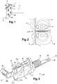
- the figure 1 shows an example of bonding that one wishes to achieve with a device according to the invention. It is a question of sticking two plates 1 and 2 (in the example two samples of reduced size) of electrically conductive material, for example metallic materials or composite materials containing carbon fibers. All the examples provided in the present description apply to the assembly of two electrically conductive parts, but it is understood that the invention also applies to the assembly of two parts of which only one is in one electrically conductive material. In order to be able to assemble these plates by gluing, a thermally activatable adhesive, for example a thermosetting adhesive 3, intended to be heated by conduction, with which the faces to be joined together with plates 1 and 2 will be bonded.
- a thermally activatable adhesive for example a thermosetting adhesive 3 intended to be heated by conduction, with which the faces to be joined together with plates 1 and 2 will be bonded.
- This adhesive may or may not be "charged”, that is to say contain or not conductive particles making it reactive to induction heating.
- the principle of induction heating implemented by the invention is represented on the figure 2 : an induction coil 4 (here shown in section) is brought close to the assembly formed by the two plates whose facing faces are glued. The axis of the coil 4 is substantially perpendicular to the surface of the front plate 1, itself substantially parallel to the rear plate 2. The heating of the adhesive is indirectly carried out, as shown in FIG.
- the induction coil 4 by means of the induction coil 4: this will allow to heat the plates to be assembled, which will heat the adhesive by thermal conduction. Indeed, when the coil 4 is powered by alternating currents of predetermined intensity and frequency, it generates an electromagnetic field (the general shape of the field lines 5 is represented on the figure 2 ) which induces currents in the plates 1 and 2 which are conductive. In order to effectively heat the adhesive, it is necessary that the magnetic field reaches not only the front plate 1, but also the back plate 2.
- the figures 3 and 4 show an exemplary embodiment of a bonding tool according to the invention: it comprises in this configuration an applicator 10 and a separate capacity box 20.
- the capacity box 20 contains a series of capacitors connected in parallel and which can be separately connected or disconnected by means of a system of pads, so as to vary the total capacitance of the capacity box 20.
- This adaptability of the capacitance box makes it possible to optimize the operation of the applicator 10 according to the generator of induction to feed it. Indeed, to use the induction generator at the desired frequency and at an optimized power, it is necessary that the total impedance of the load that it feeds, which can be likened to a circuit type "RLC" , adapted to its own impedance.
- the capacitance C of the load is therefore required as the adjustment variable, the one which is the simplest of vary to obtain the desired impedance.
- a separate capacitor box provides easy access to the stud system for adjusting capacity.
- the capacity box could be an integral part of the applicator 10.
- the adjustable capacity box will allow very fine adjustment of the frequency of the current supplied by the induction generator within a frequency range compatible with its operation.
- the inductive means will be controlled primarily by frequency: first of all it will be sought to feed the induction coil at a determined frequency because for materials with fixed characteristics, the frequency Inductive currents will determine the depth of penetration of the magnetic field (and therefore the thickness of material subject to induction heating). So, the frequency of the alternating current supplying the coil 18 will be determined precisely for each application, in particular according to the nature and the thickness of the materials to be assembled.
- the magnetic field that it generates passes through the first plate and reaches the front face of the second plate. It must indeed be ensured that the faces in contact of the two plates to be assembled are correctly heated.
- the depth of penetration of the magnetic field generated by the coil will be a function of the frequency thereof, and therefore of the frequency of the current supplied by the induction generator. This frequency will therefore finely adjust the operation of the applicator according to the parts to be assembled.
- the induction frequency is controlled in a range between 70 kHz and 140 kHz depending on the nature and the thickness of the parts 1 and 2 to be assembled, so that the temperature T3 in the adhesive reaches the crosslinking temperature of said adhesive throughout its thickness while the temperatures T1 and T2 of the parts to be assembled, and more particularly the temperature T1 on the surface of the part 1 induction coil side, remain below the temperature of thermal degradation of the material constituting said parts.
- the parts to be assembled consist of a composite material comprising a fibrous reinforcement, said reinforcement being electrically conductive, in a matrix, in particular epoxide, electrically and thermally insulating
- the choice of the induction frequency is essential to obtain heating the adhesive through the two pieces.
- a frequency that is too high for the induction current heats up the placed reinforcing layer. the closest to the inductor, the heat propagates very difficult by conduction in the thickness of the room, so that the resin is thermally degraded before the adhesive has reached the proper temperature of bonding.
- a frequency too low for example less than 50 kHz, the currents pass through the thickness of the assembly without causing significant heating.
- the applicator will be powered by an alternating current of fixed frequency.
- the bonding tool according to the invention is described below, in its variant with a box of separate capacity.
- the applicator 10 can be manipulated directly by an operator or fixed at the end of a robot arm and thus implemented automatically.
- the figure 3 presents a variant of the applicator more particularly intended to be used directly by an operator.
- the applicator comprises a body 11 of axis XX ', the body comprising at a front end an induction coil of axis substantially perpendicular to the axis XX'.
- the body 11 comprises two handling handles, a main handle or rear handle 12 and an auxiliary handle or front handle 13.
- the main handle 12 is disposed near the vertical center of gravity of the applicator, in a substantially parallel direction to the axis XX '.
- the auxiliary handle 13 is arranged in front of the main handle 12.
- the auxiliary handle is arranged in such a way that the axis formed by the leg of the "T" of the handle is perpendicular to the axis XX '. axis being close or confused with the axis of the induction coil. So, in the configuration of the figure 3 , the applicator 10 is intended to be mainly used in horizontal position (that is to say with the axis XX 'of substantially horizontal direction). This configuration is particularly suitable for assembling panels arranged horizontally, the main handle 12 for supporting the applicator while the auxiliary handle 13 allows to exert a pressure of substantially vertical directional pressure.
- a control box 14 comprising in the example two buttons 14 1 , 14 2 , allowing the operator to control the various functions of the applicator.
- a flexible sheath 15 for example of thermoplastic material, which contains the energy feeds 16, in particular electrical current and cooling fluid.
- These leads 16, as well as the flexible sheath 15, are connected to the capacity box 20.
- the sheath 15 containing the energy supply may be shielded to limit the level of electromagnetic radiation in the environment. In all cases, this sheath 15 must allow the movements necessary for the implementation of the applicator 10.
- the tool head 17 comprises a rigid shielding casing 17 1 inside which is trapped the induction coil 18.
- the outer diameter of the coil will be small, for example less than 30 millimeters.
- the free end of the tool head comprises a contact head 17 2 .
- the contact head 17 2 has at its free end a contact surface 17 3 , preferably substantially flat and substantially perpendicular to the axis of the induction coil 18.
- This contact surface 17 3 ensures the dual function of allowing the operator on the one hand, to exert a force with the applicator (in order to exert a creep stress on the adhesive and / or obtain a determined spacing between the plates) and, d ' on the other hand, to benefit from a safe and repeatable automatic referencing, the distance between the coil and the contact surface being invariable.
- the induction coil will always be arranged at the same predetermined distance from the anterior plate, regardless of the number of repeated bonding operations.
- the figure 5 shows the body 11 partially disassembled, distinguish the shield casing 17 1 associated with the contact head 17 2 .
- the contact head 17 2 consists of a removable electrically insulating pad, for example plastic, elastomer, or composite material or ceramic.
- a removable electrically insulating pad for example plastic, elastomer, or composite material or ceramic.
- the contact head 17 2 is removable, it is possible to instantly vary the thickness thereof by a simple exchange with a pellet of appropriate thickness. This allows a quick and fine adjustment of the referencing distance of the coil vis-à-vis the plate on which the applicator must be used, while ensuring the required repeatability.
- the winding axis of the coil is substantially perpendicular to the axis XX 'of the body 11. This configuration corresponds to ergonomics optimized for an operator. However, we can consider any kind of alternative configuration, especially that the axis of the coil is parallel to the axis of the body 11.
- the applicator 10 will be equipped with a temperature measuring device such as a pyrometer, to control the heating temperature obtained by the applicator.
- a temperature measuring device such as a pyrometer
- the probe 19 is positioned to measure the temperature of the front plate. It is also possible, in addition or in substitution, to position a probe so as to measure the temperature of the back plate.
- a Bragg grating optical measurement system comprising an optical fiber 22 inserted in the tool head 17 of the applicator, and positioned in a hole opening on the contact surface of the contact head 17 2 .
- Such a system makes it possible to measure the temperature as close to the place heated by the applicator 10, and also has the advantage of not being disturbed by the magnetic field.
- the applicator is provided with pressure means 21 arranged opposite the contact head 17 2 , and to operate, when possible and necessary, a pinch of the two parts to assemble.
- the pressure means 21 comprise a jaw 21 1 disposed opposite the contact head 17 2 .
- This jaw is articulated on an angle 21 2 , and is thus actuated by a pneumatic actuator 21 3 disposed under the body 11, parallel thereto.
- This actuator may be linear, for example a pneumatic jack, or rotary, associated with a nut / worm system.
- FIG. 7 An alternative embodiment of the induction coil 18 is shown on the figure 7 Instead of a conventional coil formed of a single winding, there is provided a coil 18 comprising a double winding.
- the two supply strands of the coil 18 1 and 18 2 form two concentric windings, an inner winding of smaller diameter and an outer winding of larger diameter. This produces a coil for obtaining a more restricted and more concentrated heating zone.
- a phenomenon inherent to single-wound coils is avoided: the disturbance of the lines of the magnetic field caused by one of the supply strands running along the coil (outside or inside the coils of the coil). ci), which breaks the central symmetry of an "ideal" coil.
- an induction generator capable of producing an alternating current of predetermined intensity and frequency in order to supply the induction coil.
- the operating parameters of the generator will of course be adapted according to the nature of the bonding concerned (type of material to be assembled, nature of the adhesive, etc.). For example, frequencies of between 50 and 100 kHz are envisaged for parts to be assembled in composite material based on carbon fibers, the fine tuning of the frequency then depending essentially on the thicknesses of the parts to be assembled.
- the capacity box 20 is connected in parallel with the induction coil 18.
- the connection between the generator and the capacitance box is made by simple electrical cables adapted to the intensity of the current supplied by the generator.
- connection between the capacitor box 20 and the applicator 10 is in practice an inductor over its entire length (in addition to the coil 18 itself), with the loss of efficiency and the problems of electromagnetic radiation that implies. It is therefore advantageous, when feasible, to minimize the length of the capacitor / applicator box link in favor of the link generator / cabinet capacity. Furthermore, the choice of an applicator and a separate capacitance box allows in particular to reduce the weight of the applicator, which is particularly interesting in the case of manual manipulation of the applicator. However, it will be possible to combine these two subsets in a single device, for example if it is robotized, or, as mentioned above, if the use of a fixed capacity is possible.
- each feed 16 comprises an insulating pipe, for example made of reinforced PVC, inside which is disposed an electrical conductor, for example a copper braid of suitable diameter, and in which a heat transfer fluid is circulated. such as water.
- the feeds 16 are protected within the flexible sheath 15 connecting the capacity box 20 to the applicator 10.
- the figure 8 shows an example of integration of the tool object of the invention within a workstation 30, thus forming an assembly system according to the invention.
- the workstation comprises a console 300 and a table 301, these two elements being, in the example, rolling and independent.
- the table 301 is able to support a fastening frame 303 for holding parts 304a, 304b to be assembled.
- the console 300 is equipped with housings respectively receiving the induction generator 302 and the capacity box 20.
- the console 300 is provided with a horizontal support arm 305 for suspending the supply duct 15 as well as for that of the applicator 10 by means of a cable 307 and an automatic winding device, or balancer 306.
- the support arm 305 is articulated about a vertical axis relative to the console 302.
- the suspension elements the sheath 15 and the applicator 10 are able to move easily along the support arm 305, thus making it possible not to hinder the movements of the operator provided with the applicator 10.
- the control of the tool according to the invention can be simplified to the maximum, with for example a single command triggering the heating for a predetermined time if the applicator is piloted in heating time, or until a set temperature is reached if it is temperature controlled.
- this single command can also control their implementation, also for a predetermined time and with a predetermined force.
- the implementation of the pressure means may be simultaneous or deferred with respect to the implementation of the heating, as required.
Landscapes
- Engineering & Computer Science (AREA)
- Mechanical Engineering (AREA)
- Physics & Mathematics (AREA)
- Thermal Sciences (AREA)
- Electromagnetism (AREA)
- Chemical & Material Sciences (AREA)
- Chemical Kinetics & Catalysis (AREA)
- General Chemical & Material Sciences (AREA)
- General Induction Heating (AREA)
- Adhesives Or Adhesive Processes (AREA)
Description
- La présente invention se rapporte à un dispositif d'assemblage par collage comportant des moyens de chauffage inductif, permettant la réticulation de points ou de bandes d'un matériau adhésif, tel qu'une colle, notamment dans le but d'assembler des pièces.
- Le dispositif objet de l'invention est particulièrement adapté à l'assemblage de matériaux composites comportant au moins une phase conductrice de l'électricité, tels que des composites comprenant une matrice organique renforcée par des fibres de carbone
- Des méthodes pour assembler des structures formées de panneaux électriquement conducteurs au moyen d'un adhésif thermodurcissable chauffé par induction, sont connues de l'art antérieur. Les adhésifs thermodurcissables sont des adhésifs dont la réticulation (ou polymérisation) est obtenue par activation thermique ou par réaction à un rayonnement ultraviolet. Cette réticulation à chaud est obtenue pour certains adhésifs par une réaction exothermique consécutive au mélange de deux composants constitutifs de l'adhésif. D'autres adhésifs nécessitent une source de chaleur externe afin de susciter leur activation thermique. Pour cette dernière catégorie, de nombreuses solutions ont été développées dans le but de réaliser efficacement l'activation thermique de l'adhésif employé.
- Un moyen efficace d'apporter la chaleur nécessaire à la réticulation de l'adhésif est le chauffage par induction, à condition que l'adhésif ou au moins un des éléments de la structure à assembler soit électriquement conducteur.
- A titre d'exemple brevet américain
US-B-4 528 057 décrit une presse apte à réaliser le collage par point de deux plaques métalliques, au moyen d'un adhésif thermodurcissable déposé en revêtement sur la face en vis-à-vis de l'une des plaques. La bobine d'induction sensiblement cylindrique dont l'axe s'étend sensiblement perpendiculairement à l'interface d'assemblage permet de générer un chauffage par induction des plaques métalliques, dans une zone délimitée dans laquelle les plaques sont maintenues fermement en contact l'une de l'autre et ainsi de cuire l'adhésif pour provoquer le collage. - Lorsque les plaques à assembler ne sont pas conductrices, un suscepteur peut être utilisé. Un tel suscepteur est constitué, par exemple, d'une feuille métallique, laquelle feuille métallique est placée entre les plaques à assembler au contact de l'adhésif. Ainsi les courants induits agissent sur le suscepteur, qui, transmettant sa chaleur à l'adhésif, permet la fusion ou la réticulation du dit adhésif et l'assemblage des plaques. Une telle solution est décrite par exemple dans la demande de brevet américaine publiée sous la référence
US-A-2004/0050839 . Dans cet exemple de réalisation de l'art antérieur, la répartition de l'énergie thermique dans l'épaisseur de l'adhésif est calibrée par le nombre et la position des suscepteurs au contact de la couche adhésive et la sélection de la puissance de l'induction en fonction de l'épaisseur de la couche adhésive et de l'épaisseur des suscepteurs. La présence de ces suscepteurs qui restent prisonniers de la couche adhésive n'est pas toujours adaptée au collage de pièces structurales. - Dans le cas de l'assemblage de matériaux composites, particulièrement lorsque ceux-ci sont constitués d'une phase conductrice de l'électricité, telle que des fibres de carbone et une phase isolante, telle qu'une résine époxyde, ces techniques de l'art antérieur sont peu opérantes car la phase conductrice est susceptible d'agir comme une cage de Faraday et que la phase isolante est généralement sensible à la dégradation thermique ou brûlure. Ainsi, le suscepteur ne peut être chauffé à travers de la couche de fibres et l'augmentation de la puissance d'induction conduit à la brûlure de la phase isolante du composite.
- Afin de résoudre les insuffisances de l'art antérieur, l'invention concerne un dispositif d'assemblage permettant le collage par points, au moyen d'un adhésif activable thermiquement, notamment thermodurcissable, placé à l'interface d'assemblage, de deux pièces dont au moins une est constituée d'un matériau électriquement conducteur, notamment un matériau composite comportant une phase conductrice, le dispositif comprenant :
- une bobine d'induction destinée à chauffer la surface en contact avec l'adhésif d'au moins une des pièces à assembler en contact avec l'adhésif ;
- un carter rigide à l'intérieur duquel est disposée la bobine d'induction ;
- une tête de contact située à une extrémité libre du carter rigide, comprenant une surface de contact destinée à assurer le positionnement du dispositif par contact avec une des pièces à assembler ;
- un coffret de capacité réglable relié en parallèle à la bobine d'induction ;
- un applicateur, séparé du coffret de capacité et portant la bobine d'induction, ledit applicateur étant pourvu de moyens de mesure de température ;
- Le contrôle de la distance entre la bobine d'induction et la surface de contact, combiné au contrôle de la fréquence d'induction par le coffret de capacité permet de convoyer l'énergie de chauffage au plus proche de l'adhésif placé entre les plaques en limitant l'effet de cage de Faraday dans le cas d'une plaque en matériau composite. L'asservissement en température rendu possible par la présence de la mesure en température permet de piloter l'énergie de chauffage de sorte à éviter toute brûlure. Le contrôle de la fréquence permet en outre de chauffer par transparence directement la surface de contact entre la couche adhésive et la plaque.
- L'invention peut être mise en oeuvre selon les modes de réalisation exposés ci-après, lesquels peuvent être considérés individuellement ou selon toute combinaison techniquement opérante.
- Dans une réalisation, la tête de contact est en matériau électriquement isolant.
- Dans une réalisation, la tête de contact est démontable.
- Dans une réalisation, la tête de contact est interchangeable, son épaisseur permettant de faire varier la distance entre la bobine d'induction et la surface de contact.
- Dans une réalisation, des moyens de pression sont disposés en regard de la surface de contact.
- Selon un mode de réalisation avantageux, le coffret de capacité réglable comprend un jeu de capacités permettant de régler la fréquence entre 70 kHz et 140 kHz. Cette gamme de fréquence est particulièrement avantageuse pour le chauffage par induction de l'interface d'assemblage pièces composites comportant un renfort fibreux sous la forme de fibres de carbone.
- Selon ce mode de réalisation avantageux le coffret de capacité réglable comprend deux blocs de deux capacités en série, lesdits blocs étant connectés en parallèles. Cette configuration permet de faire varier la fréquence dans la gamme désirée de manière économique par combinaison en série ou en parallèles des capacités.
- Dans une réalisation, la bobine d'induction est une bobine à double enroulement. Cette configuration permet, de manière surprenante, une pénétration plus concentrée et plus profonde du flux magnétique.
- Dans une réalisation, la liaison électrique entre l'applicateur et le coffret de capacité est réalisée au moyen d'amenées souples.
- Ainsi le dispositif objet de l'invention permet d'assurer un chauffage particulièrement optimisé, avec un rendement et une localisation du chauffage maximisés
- Dans une réalisation, chaque amenée comprend un tuyau isolant au sein duquel on fait circuler un fluide caloporteur et comprenant un conducteur électrique souple, par exemple en cuivre.
- Dans une réalisation, les amenées sont disposées à l'intérieur d'une gaine de protection flexible.
- Dans une réalisation, le dispositif comprend une ou plusieurs poignées de manipulation, afin d'être mis en oeuvre par un opérateur.
- Dans une réalisation, le dispositif comprend des moyens pour être fixé à un bras robotisé.
- Ainsi le dispositif objet de l'invention permet un positionnement efficace, précis et répétable de la bobine d'induction vis-à-vis des pièces à assembler
- L'invention concerne également un système d'assemblage mettant en oeuvre un dispositif tel que défini ci-dessus, et comprenant un générateur d'induction relié électriquement en parallèle au dispositif.
- Dans une réalisation, le système d'assemblage comprend un support de maintien des pièces à assembler et une console de support du générateur et du dispositif d'assemblage.
- Dans une réalisation, la console de support comprend un bras articulé de support du dispositif d'assemblage.
- L'invention exposée ci-après de manière détaillée selon ses modes de réalisation préférés, nullement limitatifs, en référence aux
figures 1 à 10 dans lesquelles : - les
figures 1 et 2 montrent le principe de collage par induction selon l'invention ; - les
figures 3 à 7 montrent des perspectives d'ensemble ou partielles des différents composants d'un dispositif selon l'invention ; - la
figure 8 montre une réalisation d'un système selon l'invention ; - la
figure 9 représente un assemblage de deux pièces, de profil et en coupe ; - et la
figure 10 est un schéma électrique de principe illustrant le mode de réglage de la fréquence d'induction à partir de la connexion et série ou en parallèle de capacités. - La
figure 1 montre un exemple de collage que l'on souhaite pouvoir réaliser avec un dispositif selon l'invention. Il s'agit de coller deux plaques 1 et 2 (dans l'exemple deux échantillons de taille réduite) en matériau électriquement conducteur, par exemple des matériaux métalliques ou des matériaux composites contenant des fibres de carbone. L'ensemble des exemples fournis dans la présente description s'applique à l'assemblage de deux pièces électriquement conductrices, mais il est entendu que l'invention s'applique également à l'assemblage de deux pièces dont seulement l'une est en un matériau électriquement conducteur. Pour pouvoir assembler ces plaques par collage, on prévoit un adhésif activable thermiquement, par exemple un adhésif thermodurcissable 3, destiné à être chauffé par conduction, avec lequel on va encoller les faces à assembler des plaques 1 et 2. Afin de réaliser des points de fixation en une pluralité d'endroits espacés 3a, 3b, 3c, 3d, chacun de ces endroits va être successivement chauffé pour obtenir le durcissement de l'adhésif. Cet adhésif pourra être « chargé » ou non, c'est-à-dire contenir ou non des particules conductrices le rendant réactif au chauffage par induction. Le principe de chauffage par induction mis en oeuvre par l'invention est représenté sur lafigure 2 : une bobine d'induction 4 (ici représentée en coupe) est amenée à proximité de l'ensemble formé par les deux plaques dont les faces en regard sont encollées. L'axe de la bobine 4 est sensiblement perpendiculaire à la surface de la plaque avant 1, elle-même sensiblement parallèle à la plaque arrière 2. Le chauffage de l'adhésif est indirectement réalisé, comme montré sur lafigure 2 , au moyen de la bobine d'induction 4 : celle-ci va permettre de chauffer les plaques à assembler, qui chaufferont l'adhésif par conduction thermique. En effet, lorsque la bobine 4 est alimentée par des courants alternatifs d'intensité et de fréquence prédéterminées, elle génère un champ électromagnétique (dont la forme générale des lignes de champ 5 est représentée sur lafigure 2 ) qui induit des courants dans les plaques 1 et 2 qui sont conductrices. Afin de pouvoir chauffer efficacement l'adhésif, il est nécessaire que le champ magnétique atteigne non seulement la plaque avant 1, mais également la plaque arrière 2. - Les
figures 3 et4 montrent un exemple de réalisation d'un outil de collage selon l'invention : il comprend dans cette configuration un applicateur 10 et un coffret de capacité séparé 20. Le coffret de capacité 20 contient une série de condensateurs montés en parallèle et qui peuvent être séparément connectés ou déconnectés au moyen d'un système de plots, de manière à faire varier la capacité totale du coffret de capacité 20. Ce caractère adaptable du coffret de capacité permet d'optimiser le fonctionnement de l'applicateur 10 en fonction du générateur d'induction devant l'alimenter. En effet, pour utiliser le générateur d'induction à la fréquence désirée et à une puissance optimisée, il est nécessaire que l'impédance totale de la charge qu'il alimente, que l'on peut assimiler à un circuit de type « RLC », soit adaptée à son impédance propre. La résistance R et l'inductance L de la charge étant très fortement déterminées par les inducteurs et les éléments à chauffer, la capacité C de la charge s'impose donc comme la variable d'ajustement, celle qu'il est le plus simple de faire varier pour obtenir l'impédance voulue. De fait, un coffret de capacité séparé offre un accès facilité au système de plots permettant le réglage de la capacité. Bien entendu, dans une application qui permettrait l'utilisation d'une capacité fixe prédéterminée, le coffret de capacité pourrait faire partie intégrante de l'applicateur 10. - En pratique, le coffret de capacité réglable va permettre d'ajuster très finement la fréquence du courant fourni par le générateur d'induction à l'intérieur d'une plage de fréquences compatible avec son fonctionnement. En effet, dans la plupart des applications de la présente invention, les moyens inductifs seront pilotés prioritairement en fréquence : on cherchera en effet en premier lieu à alimenter la bobine d'induction à une fréquence déterminée car pour des matériaux aux caractéristiques fixées, la fréquence des courants inducteurs déterminera la profondeur de pénétration du champ magnétique (et donc l'épaisseur de matériau sujet au chauffage par induction). Ainsi, la fréquence du courant alternatif alimentant la bobine 18 sera déterminée précisément pour chaque application, notamment en fonction de la nature et de l'épaisseur des matériaux à assembler. En effet, toujours dans le but de maximiser l'efficacité de l'outil conforme à l'invention, on s'attachera à ce que le champ magnétique qu'il génère traverse la première plaque et atteigne de façon certaine la face antérieure de la deuxième plaque. On doit en effet s'assurer que les faces en contact des deux plaques à assembler sont correctement chauffées. Pour un matériau donné, on sait que la profondeur de pénétration du champ magnétique généré par la bobine sera fonction de la fréquence de celui-ci, donc de la fréquence du courant fourni par le générateur d'induction. Cette fréquence permettra donc d'ajuster finement le fonctionnement de l'applicateur selon les pièces à assembler.
-
Figure 9 , plus précisément la fréquence de l'induction est pilotée dans une gamme comprise en 70 kHz et 140 kHz en fonction de la nature et de l'épaisseur des pièces 1 et 2 à assembler, de telle sorte que la température T3 dans l'adhésif atteigne la température de réticulation dudit adhésif dans toute son épaisseur alors que les températures T1 et T2 des pièces à assembler, et plus particulièrement la température T1 sur la surface de la pièce 1 côté bobine d'induction, restent inférieures à la température de dégradation thermique de la matière constituant lesdites pièces. Dans le cas où les pièces à assembler sont constituées d'un matériau composite comportant un renfort fibreux, ledit renfort étant électriquement conducteur, dans une matrice, notamment époxyde, électriquement et thermiquement isolante, le choix de la fréquence d'induction est primordial pour obtenir un chauffage de l'adhésif par l'intermédiaire des deux pièces. Ainsi, lorsque le renfort est placé sous forme de plis s'étendant selon des surfaces sensiblement parallèles à l'interface d'assemblage, une fréquence trop élevée du courant d'induction, par exemple supérieure à 140 kHz, échauffe la couche de renfort placée la plus proche de l'inducteur, la chaleur se propageant très difficilement par conduction dans l'épaisseur de la pièce, de sorte que la résine se dégrade thermiquement avant que l'adhésif n'ait atteint la température adéquate de collage. Dans le cas d'utilisation d'une fréquence trop faible, par exemple inférieure à 50 kHz, les courants traversent l'épaisseur de l'assemblage sans provoquer d'échauffement significatif. - Par exemple, pour assembler deux panneaux composites comprenant une matrice époxyde renforcée de fibres de carbone dont le panneau avant, côté bobine d'induction, présente une épaisseur de 0,6 mm et le second présente une épaisseur de 2,5 mm, on prévoira une fréquence de l'ordre de 80 kHz, pour une puissance d'induction comprise entre 2,4 kW et 3,2 kW. Dans ces conditions, la température T3 maximale atteinte au cours de l'opération de collage est de l'ordre de 110 °C alors que la température T1 à la surface de la pièce côté bobine d'induction reste inférieure à 130 °C. D'une manière générale, pour une application donnée (matériaux et épaisseurs des pièces définis), l'applicateur sera alimenté par un courant alternatif de fréquence fixe.
-
Figure 10 , le coffret de capacité réglable 20 est interposé entre le générateur 302 et l'applicateur 10. Les deux circuits sont séparés par un transformateur 360. Selon un exemple de réalisation de ce coffret 20, celui-ci comprend deux blocs de deux capacités C1, C2 et C3, C4 en parallèle, lesdits deux blocs étant connectés en série. La fréquence d'induction est obtenue en combinant les valeurs de capacités, par exemple : - pour une fréquence de 82 kHz : C1=C2=C3=C4=2,5 µF ;
- pour une fréquence de 110 kHz : C1=C2=0,66 µF, les capacités C3 et C4 étant shuntées ;
- pour une fréquence de 138 kHz : C1=C2=0,66 µF, C3=2,5 µF et C4 étant shuntée.
- On décrit ci-après l'outil de collage selon l'invention, dans sa variante avec coffret de capacité séparé. Selon les cas, l'applicateur 10 pourra être manipulé directement par un opérateur ou fixé au bout d'un bras de robot et donc mis en oeuvre automatiquement. La
figure 3 présente une variante de l'applicateur plus particulièrement destiné à être utilisé directement par un opérateur. L'applicateur comprend un corps 11 d'axe XX', le corps comprenant à une extrémité avant une bobine d'induction d'axe sensiblement perpendiculaire à l'axe XX'. Le corps 11 comprend deux poignées de manipulation, une poignée principale ou poignée arrière 12 et une poignée auxiliaire ou poignée avant 13. La poignée principale 12 est disposée à proximité de la verticale du centre de gravité de l'applicateur, selon une direction sensiblement parallèle à l'axe XX'. La poignée auxiliaire 13 est quant à elle disposée en avant de la poignée principale 12. La poignée auxiliaire est disposée de telle sorte que l'axe formé par la jambe du « T » de la poignée est perpendiculaire à l'axe XX', cet axe étant proche voire confondu avec l'axe de la bobine d'induction. Ainsi, dans la configuration de lafigure 3 , l'applicateur 10 est prévu pour être principalement utilisé en position horizontale (c'est-à-dire avec l'axe XX' de direction sensiblement horizontale). Cette configuration est particulièrement adaptée à l'assemblage de panneaux disposés horizontalement, la poignée principale 12 permettant de soutenir l'applicateur tandis que la poignée auxiliaire 13 permet d'exercer un effort de pression de direction sensiblement verticale. - Entre les deux poignées 12, 13 est disposé, sur une partie supérieure du corps 11, un boîtier de commande 14, comportant dans l'exemple deux boutons de commande 141, 142, permettant à l'opérateur de commander les différentes fonctions de l'applicateur. À une extrémité arrière du corps est disposée une gaine flexible 15, par exemple en matière thermoplastique, qui contient les amenées 16 d'énergie, notamment de courant électrique et fluide de refroidissement. Ces amenées 16, ainsi que la gaine flexible 15, sont reliées au coffret de capacité 20. Selon les cas, la gaine 15 contenant les amenées d'énergie pourra être blindée afin de limiter le niveau de rayonnement électromagnétique dans l'environnement. Dans tous les cas, cette gaine 15 doit permettre les mouvements nécessaires à la mise en oeuvre de l'applicateur 10.
- À l'extrémité avant du corps 11 est disposée une tête d'outil 17. La tête d'outil 17 comprend un carter de blindage rigide 171 à l'intérieur duquel est emprisonnée la bobine d'induction 18. Dans le but de mieux localiser le chauffage, le diamètre externe de la bobine sera peu important, par exemple inférieur à 30 millimètres. L'extrémité libre de la tête d'outil comprend une tête de contact 172. Conformément à l'invention la tête de contact 172 présente à son extrémité libre une surface de contact 173, de préférence sensiblement plane et sensiblement perpendiculaire à l'axe de la bobine d'induction 18. Cette surface de contact 173 assure la double fonction de permettre à l'opérateur d'une part, d'exercer un effort avec l'applicateur (afin d'exercer une contrainte de fluage sur l'adhésif et/ou obtenir un espacement déterminé entre les plaques) et, d'autre part, de bénéficier d'un référencement automatique sûr et répétable, la distance entre la bobine et la surface de contact étant invariable. Ainsi, on est certain que la bobine d'induction sera toujours disposée à une même distance prédéterminée de la plaque antérieure, quel que soit le nombre d'opérations de collage répétées. La
figure 5 montre le corps 11 partiellement démonté, permettent de distinguer le carter de blindage 171 associé à la tête de contact 172. Dans l'exemple, la tête de contact 172 est constituée d'une pastille amovible électriquement isolante, par exemple en matière plastique, en élastomère, ou encore en matériau composite ou céramique. Comme la tête de contact 172 est amovible, on peut ainsi faire varier instantanément l'épaisseur de celle-ci par un simple échange avec une pastille d'épaisseur appropriée. On permet ainsi un réglage rapide et fin de la distance de référencement de la bobine vis-à-vis de la plaque sur laquelle doit être utilisé l'applicateur, tout en assurant la répétabilité requise. - Sur les
figures 3 et5 , on peut voir que l'axe d'enroulement de la bobine est sensiblement perpendiculaire à l'axe XX' du corps 11. Cette configuration correspond à une ergonomie optimisée pour un opérateur. On peut toutefois envisager toute sorte de configuration alternative, notamment que l'axe de la bobine soit parallèle à l'axe du corps 11. - De manière avantageuse, l'applicateur 10 sera équipé d'un dispositif de mesure de la température tel qu'un pyromètre, permettant de contrôler la température de chauffe obtenue par l'applicateur. Dans l'exemple de la
figure 3 , on a prévu, sur la partie avant de l'applicateur, une sonde de mesure infrarouge 19, disposée à l'extrémité d'un bras de support 190. Dans l'exemple, la sonde 19 est positionnée de manière à mesurer la température de la plaque avant. On pourra également, en addition ou en substitution, positionner une sonde de manière à mesurer la température de la plaque arrière. Dans l'exemple de lafigure 5 , on a également représenté un système de mesure optique à réseaux de Bragg, comprenant une fibre optique 22 insérée dans la tête d'outil 17 de l'applicateur, et positionnée dans un trou débouchant sur la surface de contact de la tête de contact 172. Un tel système permet de mesurer la température au plus près de l'endroit chauffé par l'applicateur 10, et présente en outre l'avantage de ne pas être perturbé par le champ magnétique. - Dans une variante de réalisation de l'invention, l'applicateur est pourvu de moyens de pression 21 disposés en regard de la tête de contact 172, et permettant d'opérer, lorsque c'est possible et nécessaire, un pincement des deux pièces à assembler. Un exemple de réalisation de cette variante est montré sur la
figure 6 . Les moyens de pression 21 comprennent une mâchoire 211 disposée en regard de la tête de contact 172. Cette mâchoire est articulée sur un renvoi d'angle 212, et est ainsi actionnée par un actionneur pneumatique 213 disposé sous le corps 11, parallèlement à celui-ci. Cet actionneur peut être linéaire, par exemple un vérin pneumatique, ou rotatif, associé à un système écrou/vis sans fin. Ainsi, lors d'une opération de collage, la présence de ces moyens de pression va permettre le pincement des deux plaques à assembler entre la mâchoire 211 et la tête de contact 172, avec un effort prédéterminé, contrôlable et répétable, le tout de manière entièrement automatique. - Une variante de réalisation de la bobine d'induction 18 est montrée sur la
figure 7 : au lieu d'une bobine classique formée d'un simple enroulement, on prévoit une bobine 18 comprenant un double enroulement. Ainsi, les deux brins d'alimentation de la bobine 181 et 182 forment deux enroulements concentriques, un enroulement interne de plus petit diamètre et un enroulement externe de plus grand diamètre. On réalise ainsi une bobine permettant d'obtenir une zone de chauffe plus restreinte et plus concentrée. De plus, on évite un phénomène inhérent aux bobines à simple enroulement : la perturbation des lignes du champ magnétique causée par l'un des brins d'alimentation qui longe la bobine (à l'extérieur ou à l'intérieur des spires de celle-ci), et qui rompt la symétrie centrale d'une bobine « idéale ». - Afin d'alimenter l'applicateur 10, il est nécessaire de prévoir un générateur d'induction, pouvant produire un courant alternatif d'intensité et de fréquence prédéterminées afin d'alimenter la bobine d'induction. Les paramètres de fonctionnement du générateur seront bien entendu adaptés en fonction de la nature du collage concerné (type de matériau à assembler, nature de l'adhésif, etc.). Par exemple, on prévoit des fréquences comprises entre 50 et 100 kHz pour des pièces à assembler en matériau composite à base de fibres de carbone, l'adaptation fine de la fréquence dépendant ensuite essentiellement des épaisseurs des pièces à assembler. Le coffret de capacité 20 est connecté en parallèle de la bobine d'induction 18. La liaison entre le générateur et le coffret de capacité est réalisée par de simples câbles électriques adaptés à l'intensité du courant fourni par le générateur. La liaison entre le coffret de capacité 20 et l'applicateur 10 constitue en pratique un inducteur sur toute sa longueur (en plus de la bobine 18 en elle-même), avec la perte de rendement et les problèmes de rayonnement électromagnétique que cela implique. Il y a donc intérêt, lorsque c'est faisable, à minimiser la longueur de la liaison coffret de capacité/applicateur au profit de la liaison générateur/coffret de capacité. Par ailleurs, le choix d'un applicateur et d'un coffret de capacité séparés permet notamment de réduire le poids de l'applicateur, ce qui est particulièrement intéressant dans le cas d'une manipulation manuelle de l'applicateur. On pourra toutefois envisager de réunir ces deux sous-ensembles dans un dispositif unique, par exemple si celui-ci est robotisé, ou, comme évoqué plus haut, si l'utilisation d'une capacité fixe est possible.
- Dans l'exemple, le coffret de capacité est un coffret séparé, et il est relié électriquement à l'applicateur par des amenées souples. Ces amenées doivent permettre l'alimentation en courant de la bobine d'induction 18, tout en assurant un refroidissement de cette liaison qui peut être soumise à des courants de très forte intensité. Dans l'exemple, chaque amenée 16 comprend un tuyau isolant, par exemple en PVC armé, à l'intérieur duquel est disposé un conducteur électrique, par exemple une tresse de cuivre de diamètre adapté, et au sein duquel on fait circuler un fluide caloporteur tel que de l'eau. Les amenées 16 sont protégées au sein de la gaine flexible 15 reliant le coffret de capacité 20 à l'applicateur 10.
- La
figure 8 montre un exemple d'intégration de l'outil objet de l'invention au sein d'un poste de travail 30, formant ainsi un système d'assemblage conforme à l'invention. Le poste de travail comprend une console 300 et une table 301, ces deux éléments étant, dans l'exemple, roulants et indépendants. La table 301 est apte à supporter un cadre de fixation 303 destiné au maintien des pièces 304a, 304b à assembler. La console 300 est équipée de logements recevant respectivement le générateur d'induction 302 et le coffret de capacité 20. La console 300 est pourvue d'un bras horizontal de support 305 destiné à la suspension de la gaine d'amenées 15 ainsi qu'à celle de l'applicateur 10 au moyen d'un câble 307 et d'un dispositif à enroulement automatique, ou équilibreur 306. Le bras de support 305 est articulé autour d'un axe vertical par rapport à la console 302. Les éléments de suspension de la gaine 15 et de l'applicateur 10 sont aptes à se déplacer facilement le long du bras de support 305, permettant ainsi de ne pas entraver les mouvements de l'opérateur muni de l'applicateur 10. - Pour l'opérateur, la commande de l'outil conforme à l'invention peut être simplifiée au maximum, avec par exemple une commande unique déclenchant la chauffe pendant un temps prédéterminé si l'applicateur est piloté en temps de chauffe, ou jusqu'à ce qu'une température de consigne soit atteinte s'il est piloté en température. Dans le cas où l'outil est équipé de moyens additionnels de pression, cette commande unique peut également contrôler leur mise en oeuvre, également pendant un temps déterminé et avec une force prédéterminée. La mise en oeuvre des moyens de pression pourra être simultanée ou différée par rapport à la mise en oeuvre du chauffage, selon les besoins.
Claims (15)
- Dispositif d'assemblage pour le collage par points, au moyen d'un adhésif thermodurcissable (3) placé à l'interface d'assemblage, de deux pièces (1, 2) constituées d'un matériau composite comportant une phase conductrice susceptible d'agir comme une cage de Faraday dans une matrice isolante sensible à la dégradation thermique, lequel dispositif comporte:- une bobine d'induction (18) ;- un carter rigide (171) à l'intérieur duquel est disposée la bobine d'induction ;- une tête de contact (172) située à une extrémité libre du carter rigide (171), comprenant une surface de contact (173) destinée à assurer lepositionnement du dispositif par contact avec une des pièces à assembler;- un applicateur (10) séparé du coffret de capacité et portant la bobine d'induction, ledit applicateur étant pourvu de moyens de mesure de température (19, 22). ;- le dispositif étant agencé de sorte que la distance entre la bobine d'induction et la surface de contact est fixe, la surface de contact (173) étant sensiblement perpendiculaire à l'axe d'enroulement de la bobine ;- caractérisé en ce qu'il comprend un coffret de capacité (20) réglable relié en parallèle à la bobine d'induction (18) comprenant un jeu de capacités (C1, C2, C3, C4) pour régler la fréquence du courant électrique circulant dans la bobine d'induction entre 70 kHz et 140 kHz, de sorte à chauffer l'adhésif à sa température de réticulation sans dégrader lematériau constituant les pièces à assembler.
- Dispositif selon la revendication 1, dans lequel la tête de contact (172) est en matériau électriquement isolant.
- Dispositif selon la revendication 2, dans lequel la tête de contact (172) est démontable.
- Dispositif selon la revendication 3, dans lequel la tête de contact (172) est interchangeable, son épaisseur permettant de faire varier ladistance entre la bobine d'induction et la surface de contact (173).
- Dispositif selon la revendication 1, dans lequel des moyens de pression (21) sont disposés en regard de la surface de contact (173).
- Dispositif selon la revendication 1, caractérisé en ce que le coffret de capacité (20) réglable comprend deux blocs de deux capacités (C1, C2 et C3, C4) en parallèle, lesdits blocs étant connectés en série.
- Dispositif selon la revendication 1, dans lequel la bobine d'induction (18) est une bobine à double enroulement.
- Dispositif selon la revendication 1, dans lequel la liaison électrique entre l'applicateur (10) et le coffret de capacité (20) est réalisée au moyen d'amenées souples (16).
- Dispositif selon la revendication 8, dans lequel chaque amenée (16) comprend un tuyau isolant au sein duquel on fait circuler un fluide caloporteur et comprenant un conducteur électrique souple, par exemple en cuivre.
- Dispositif selon les revendications 8 ou 9, dans lequel les amenées (16) sont disposées à l'intérieur d'une gaine de protection flexible (15).
- Dispositif selon la revendication 1, comprenant une ou plusieurs poignées de manipulation (12, 13) afin d'être mis en oeuvre par un opérateur.
- Dispositif selon la revendication 1, comprenant des moyens pour être fixé à un bras robotisé.
- Système d'assemblage mettant en oeuvre un dispositif selon l'une des revendications 1 à 12, comprenant un générateur d'induction (302) relié électriquement en parallèle au dispositif.
- Système d'assemblage selon la revendication 13, comprenant un support (301) de maintien des pièces à assembler et une console de support (300) du générateur (302) et du dispositif d'assemblage.
- Système d'assemblage selon la revendication 13, dans lequel la console de support (300) comprend un bras articulé (305) de support du dispositif d'assemblage.
Applications Claiming Priority (2)
| Application Number | Priority Date | Filing Date | Title |
|---|---|---|---|
| FR0959566A FR2954888B1 (fr) | 2009-12-24 | 2009-12-24 | Dispositif d'assemblage par collage utilisant un chauffage par induction |
| PCT/EP2010/070718 WO2011076945A1 (fr) | 2009-12-24 | 2010-12-24 | Dispositif d'assemblage par collage utilisant un chauffage par induction |
Publications (2)
| Publication Number | Publication Date |
|---|---|
| EP2517532A1 EP2517532A1 (fr) | 2012-10-31 |
| EP2517532B1 true EP2517532B1 (fr) | 2017-07-12 |
Family
ID=42358405
Family Applications (1)
| Application Number | Title | Priority Date | Filing Date |
|---|---|---|---|
| EP10796428.0A Not-in-force EP2517532B1 (fr) | 2009-12-24 | 2010-12-24 | Dispositif d'assemblage par collage utilisant un chauffage par induction |
Country Status (3)
| Country | Link |
|---|---|
| EP (1) | EP2517532B1 (fr) |
| FR (1) | FR2954888B1 (fr) |
| WO (1) | WO2011076945A1 (fr) |
Cited By (1)
| Publication number | Priority date | Publication date | Assignee | Title |
|---|---|---|---|---|
| EP4468821A1 (fr) * | 2023-05-24 | 2024-11-27 | SMS group GmbH | Dispositif de chauffage par induction, ligne de production et utilisation d'un dispositif de chauffage par induction et procédé de fonctionnement d'un tel dispositif de chauffage par induction |
Families Citing this family (2)
| Publication number | Priority date | Publication date | Assignee | Title |
|---|---|---|---|---|
| USD719596S1 (en) | 2012-12-20 | 2014-12-16 | Sfs Intec Holding Ag | Induction apparatus |
| FR3016548A1 (fr) * | 2014-01-17 | 2015-07-24 | Eder Numero 1 | Dispositif d'impression en trois dimensions, par le procede de depot de filament fondu, de tous materiaux couche par couche |
Family Cites Families (4)
| Publication number | Priority date | Publication date | Assignee | Title |
|---|---|---|---|---|
| ZA73969B (en) * | 1972-02-29 | 1974-09-25 | Illinois Tool Works | Induction heating unit |
| US4528057A (en) * | 1983-09-08 | 1985-07-09 | The Taylor-Winfield Corporation | Adhesive spot curing press and method for metallic parts |
| GB2325982B (en) * | 1998-05-20 | 1999-08-04 | Valro Mfg Ltd | Portable induction heater |
| CA2392078C (fr) * | 1999-11-03 | 2005-02-22 | Nexicor Llc | Outil a induction a main |
-
2009
- 2009-12-24 FR FR0959566A patent/FR2954888B1/fr not_active Expired - Fee Related
-
2010
- 2010-12-24 WO PCT/EP2010/070718 patent/WO2011076945A1/fr not_active Ceased
- 2010-12-24 EP EP10796428.0A patent/EP2517532B1/fr not_active Not-in-force
Non-Patent Citations (1)
| Title |
|---|
| None * |
Cited By (1)
| Publication number | Priority date | Publication date | Assignee | Title |
|---|---|---|---|---|
| EP4468821A1 (fr) * | 2023-05-24 | 2024-11-27 | SMS group GmbH | Dispositif de chauffage par induction, ligne de production et utilisation d'un dispositif de chauffage par induction et procédé de fonctionnement d'un tel dispositif de chauffage par induction |
Also Published As
| Publication number | Publication date |
|---|---|
| WO2011076945A1 (fr) | 2011-06-30 |
| EP2517532A1 (fr) | 2012-10-31 |
| FR2954888A1 (fr) | 2011-07-01 |
| FR2954888B1 (fr) | 2013-05-10 |
Similar Documents
| Publication | Publication Date | Title |
|---|---|---|
| CA2718485C (fr) | Dispositif de transformation de materiaux utilisant un chauffage par induction et des moyens de compactage deformables | |
| EP1894442B1 (fr) | Dispositif de chauffage par induction et procede de fabrication de pieces a l'aide d'un tel dispositif | |
| EP0984853B1 (fr) | Outillage de reparation sur site d'une structure composite presentant une zone endommagee et procede correspondant | |
| CA2559925C (fr) | Procede pour chauffer des materiaux en vue de produire des objets et dispositif mettant en oeuvre ce procede | |
| EP1575336B1 (fr) | Module d'assemblage de bobines d'induction d'une zone de cuisson par chauffage par induction et zone de cuisson comprenant lesdits modules | |
| EP0713351A1 (fr) | Foyer de cuisson à induction | |
| EP3455044B1 (fr) | Dispositif et procédé pour le moulage et la consolidation d'une préforme textile | |
| EP2517532A1 (fr) | Dispositif d'assemblage par collage utilisant un chauffage par induction | |
| EP0772955B1 (fr) | Inducteur et procede de realisation d'un inducteur | |
| EP2312967B1 (fr) | Dispositif de lissage des cheveux integrant des moyens de chauffage | |
| EP2796265B1 (fr) | Appareil de réparation par chauffage d'une surface en matériau composite, au moyen d'un organe chauffant "suscepteur" activé localement par une pluralité de bobines d'induction | |
| WO2015150515A1 (fr) | Procédé et installation de réalisation d'une pièce en matériau composite | |
| KR101832193B1 (ko) | 용접예열히터 | |
| WO2008142337A2 (fr) | Procede et dispositif de chauffage de pieces tubulaires ou pleines par induction | |
| FR3066010B1 (fr) | Module chauffant pour appareil de chauffage electrique | |
| FR2793468A1 (fr) | Pale de rotor d'helicoptere repliable avec boite de spirale de cable et dispositif de cable | |
| FR2730118A3 (fr) | Element chauffant a resistance electrique | |
| WO2014083114A1 (fr) | Rotor de moteur electrique a manchon exterieur forme par enroulement, procede de fabrication d'un tel rotor et moteur electrique comprenant un tel rotor | |
| BE1021035B1 (fr) | Procede pour l'assemblage de feuilles de materiaux et dispositif pour sa mise en oeuvre | |
| FR2649576A1 (fr) | Plaque de cuisson par chauffage par induction | |
| CH622729A5 (en) | Press for induction brazing metal workpieces including raised or curved peripheral portions | |
| EP1420614A1 (fr) | Dispositif inducteur pour foyer de cuisson par induction | |
| CA2908449C (fr) | Appareil de chauffage avec dispositif de securite | |
| FR3007828A1 (fr) | Element chauffant et chauffe-eau comportant un tel element chauffant | |
| FR2982521A1 (fr) | Procede de desassemblage de deux elements soudes par ultrason et element apte a etre soude par ultrason a un autre element permettant la mise en oeuvre dudit procede |
Legal Events
| Date | Code | Title | Description |
|---|---|---|---|
| PUAI | Public reference made under article 153(3) epc to a published international application that has entered the european phase |
Free format text: ORIGINAL CODE: 0009012 |
|
| 17P | Request for examination filed |
Effective date: 20120722 |
|
| AK | Designated contracting states |
Kind code of ref document: A1 Designated state(s): AL AT BE BG CH CY CZ DE DK EE ES FI FR GB GR HR HU IE IS IT LI LT LU LV MC MK MT NL NO PL PT RO RS SE SI SK SM TR |
|
| DAX | Request for extension of the european patent (deleted) | ||
| GRAP | Despatch of communication of intention to grant a patent |
Free format text: ORIGINAL CODE: EPIDOSNIGR1 |
|
| INTG | Intention to grant announced |
Effective date: 20160819 |
|
| RAP1 | Party data changed (applicant data changed or rights of an application transferred) |
Owner name: ROCTOOL |
|
| GRAS | Grant fee paid |
Free format text: ORIGINAL CODE: EPIDOSNIGR3 |
|
| GRAJ | Information related to disapproval of communication of intention to grant by the applicant or resumption of examination proceedings by the epo deleted |
Free format text: ORIGINAL CODE: EPIDOSDIGR1 |
|
| GRAL | Information related to payment of fee for publishing/printing deleted |
Free format text: ORIGINAL CODE: EPIDOSDIGR3 |
|
| GRAP | Despatch of communication of intention to grant a patent |
Free format text: ORIGINAL CODE: EPIDOSNIGR1 |
|
| INTC | Intention to grant announced (deleted) | ||
| INTG | Intention to grant announced |
Effective date: 20170202 |
|
| GRAA | (expected) grant |
Free format text: ORIGINAL CODE: 0009210 |
|
| AK | Designated contracting states |
Kind code of ref document: B1 Designated state(s): AL AT BE BG CH CY CZ DE DK EE ES FI FR GB GR HR HU IE IS IT LI LT LU LV MC MK MT NL NO PL PT RO RS SE SI SK SM TR |
|
| REG | Reference to a national code |
Ref country code: GB Ref legal event code: FG4D Free format text: NOT ENGLISH |
|
| REG | Reference to a national code |
Ref country code: CH Ref legal event code: EP |
|
| REG | Reference to a national code |
Ref country code: AT Ref legal event code: REF Ref document number: 909421 Country of ref document: AT Kind code of ref document: T Effective date: 20170715 |
|
| REG | Reference to a national code |
Ref country code: IE Ref legal event code: FG4D Free format text: LANGUAGE OF EP DOCUMENT: FRENCH |
|
| REG | Reference to a national code |
Ref country code: DE Ref legal event code: R096 Ref document number: 602010043620 Country of ref document: DE |
|
| REG | Reference to a national code |
Ref country code: NL Ref legal event code: FP |
|
| REG | Reference to a national code |
Ref country code: LT Ref legal event code: MG4D |
|
| REG | Reference to a national code |
Ref country code: AT Ref legal event code: MK05 Ref document number: 909421 Country of ref document: AT Kind code of ref document: T Effective date: 20170712 |
|
| REG | Reference to a national code |
Ref country code: FR Ref legal event code: PLFP Year of fee payment: 8 |
|
| PG25 | Lapsed in a contracting state [announced via postgrant information from national office to epo] |
Ref country code: HR Free format text: LAPSE BECAUSE OF FAILURE TO SUBMIT A TRANSLATION OF THE DESCRIPTION OR TO PAY THE FEE WITHIN THE PRESCRIBED TIME-LIMIT Effective date: 20170712 Ref country code: FI Free format text: LAPSE BECAUSE OF FAILURE TO SUBMIT A TRANSLATION OF THE DESCRIPTION OR TO PAY THE FEE WITHIN THE PRESCRIBED TIME-LIMIT Effective date: 20170712 Ref country code: AT Free format text: LAPSE BECAUSE OF FAILURE TO SUBMIT A TRANSLATION OF THE DESCRIPTION OR TO PAY THE FEE WITHIN THE PRESCRIBED TIME-LIMIT Effective date: 20170712 Ref country code: LT Free format text: LAPSE BECAUSE OF FAILURE TO SUBMIT A TRANSLATION OF THE DESCRIPTION OR TO PAY THE FEE WITHIN THE PRESCRIBED TIME-LIMIT Effective date: 20170712 Ref country code: SE Free format text: LAPSE BECAUSE OF FAILURE TO SUBMIT A TRANSLATION OF THE DESCRIPTION OR TO PAY THE FEE WITHIN THE PRESCRIBED TIME-LIMIT Effective date: 20170712 Ref country code: NO Free format text: LAPSE BECAUSE OF FAILURE TO SUBMIT A TRANSLATION OF THE DESCRIPTION OR TO PAY THE FEE WITHIN THE PRESCRIBED TIME-LIMIT Effective date: 20171012 |
|
| PG25 | Lapsed in a contracting state [announced via postgrant information from national office to epo] |
Ref country code: IS Free format text: LAPSE BECAUSE OF FAILURE TO SUBMIT A TRANSLATION OF THE DESCRIPTION OR TO PAY THE FEE WITHIN THE PRESCRIBED TIME-LIMIT Effective date: 20171112 Ref country code: LV Free format text: LAPSE BECAUSE OF FAILURE TO SUBMIT A TRANSLATION OF THE DESCRIPTION OR TO PAY THE FEE WITHIN THE PRESCRIBED TIME-LIMIT Effective date: 20170712 Ref country code: RS Free format text: LAPSE BECAUSE OF FAILURE TO SUBMIT A TRANSLATION OF THE DESCRIPTION OR TO PAY THE FEE WITHIN THE PRESCRIBED TIME-LIMIT Effective date: 20170712 Ref country code: ES Free format text: LAPSE BECAUSE OF FAILURE TO SUBMIT A TRANSLATION OF THE DESCRIPTION OR TO PAY THE FEE WITHIN THE PRESCRIBED TIME-LIMIT Effective date: 20170712 Ref country code: BG Free format text: LAPSE BECAUSE OF FAILURE TO SUBMIT A TRANSLATION OF THE DESCRIPTION OR TO PAY THE FEE WITHIN THE PRESCRIBED TIME-LIMIT Effective date: 20171012 Ref country code: PL Free format text: LAPSE BECAUSE OF FAILURE TO SUBMIT A TRANSLATION OF THE DESCRIPTION OR TO PAY THE FEE WITHIN THE PRESCRIBED TIME-LIMIT Effective date: 20170712 Ref country code: GR Free format text: LAPSE BECAUSE OF FAILURE TO SUBMIT A TRANSLATION OF THE DESCRIPTION OR TO PAY THE FEE WITHIN THE PRESCRIBED TIME-LIMIT Effective date: 20171013 |
|
| REG | Reference to a national code |
Ref country code: DE Ref legal event code: R097 Ref document number: 602010043620 Country of ref document: DE |
|
| PG25 | Lapsed in a contracting state [announced via postgrant information from national office to epo] |
Ref country code: CZ Free format text: LAPSE BECAUSE OF FAILURE TO SUBMIT A TRANSLATION OF THE DESCRIPTION OR TO PAY THE FEE WITHIN THE PRESCRIBED TIME-LIMIT Effective date: 20170712 Ref country code: RO Free format text: LAPSE BECAUSE OF FAILURE TO SUBMIT A TRANSLATION OF THE DESCRIPTION OR TO PAY THE FEE WITHIN THE PRESCRIBED TIME-LIMIT Effective date: 20170712 Ref country code: DK Free format text: LAPSE BECAUSE OF FAILURE TO SUBMIT A TRANSLATION OF THE DESCRIPTION OR TO PAY THE FEE WITHIN THE PRESCRIBED TIME-LIMIT Effective date: 20170712 |
|
| PLBE | No opposition filed within time limit |
Free format text: ORIGINAL CODE: 0009261 |
|
| STAA | Information on the status of an ep patent application or granted ep patent |
Free format text: STATUS: NO OPPOSITION FILED WITHIN TIME LIMIT |
|
| PG25 | Lapsed in a contracting state [announced via postgrant information from national office to epo] |
Ref country code: SM Free format text: LAPSE BECAUSE OF FAILURE TO SUBMIT A TRANSLATION OF THE DESCRIPTION OR TO PAY THE FEE WITHIN THE PRESCRIBED TIME-LIMIT Effective date: 20170712 Ref country code: EE Free format text: LAPSE BECAUSE OF FAILURE TO SUBMIT A TRANSLATION OF THE DESCRIPTION OR TO PAY THE FEE WITHIN THE PRESCRIBED TIME-LIMIT Effective date: 20170712 Ref country code: SK Free format text: LAPSE BECAUSE OF FAILURE TO SUBMIT A TRANSLATION OF THE DESCRIPTION OR TO PAY THE FEE WITHIN THE PRESCRIBED TIME-LIMIT Effective date: 20170712 Ref country code: IT Free format text: LAPSE BECAUSE OF FAILURE TO SUBMIT A TRANSLATION OF THE DESCRIPTION OR TO PAY THE FEE WITHIN THE PRESCRIBED TIME-LIMIT Effective date: 20170712 |
|
| 26N | No opposition filed |
Effective date: 20180413 |
|
| REG | Reference to a national code |
Ref country code: CH Ref legal event code: PL |
|
| GBPC | Gb: european patent ceased through non-payment of renewal fee |
Effective date: 20171224 |
|
| PG25 | Lapsed in a contracting state [announced via postgrant information from national office to epo] |
Ref country code: SI Free format text: LAPSE BECAUSE OF FAILURE TO SUBMIT A TRANSLATION OF THE DESCRIPTION OR TO PAY THE FEE WITHIN THE PRESCRIBED TIME-LIMIT Effective date: 20170712 |
|
| REG | Reference to a national code |
Ref country code: IE Ref legal event code: MM4A |
|
| PG25 | Lapsed in a contracting state [announced via postgrant information from national office to epo] |
Ref country code: LU Free format text: LAPSE BECAUSE OF NON-PAYMENT OF DUE FEES Effective date: 20171224 Ref country code: MT Free format text: LAPSE BECAUSE OF FAILURE TO SUBMIT A TRANSLATION OF THE DESCRIPTION OR TO PAY THE FEE WITHIN THE PRESCRIBED TIME-LIMIT Effective date: 20170712 |
|
| REG | Reference to a national code |
Ref country code: BE Ref legal event code: MM Effective date: 20171231 |
|
| PG25 | Lapsed in a contracting state [announced via postgrant information from national office to epo] |
Ref country code: IE Free format text: LAPSE BECAUSE OF NON-PAYMENT OF DUE FEES Effective date: 20171224 |
|
| PG25 | Lapsed in a contracting state [announced via postgrant information from national office to epo] |
Ref country code: CH Free format text: LAPSE BECAUSE OF NON-PAYMENT OF DUE FEES Effective date: 20171231 Ref country code: LI Free format text: LAPSE BECAUSE OF NON-PAYMENT OF DUE FEES Effective date: 20171231 Ref country code: BE Free format text: LAPSE BECAUSE OF NON-PAYMENT OF DUE FEES Effective date: 20171231 Ref country code: GB Free format text: LAPSE BECAUSE OF NON-PAYMENT OF DUE FEES Effective date: 20171224 |
|
| PGFP | Annual fee paid to national office [announced via postgrant information from national office to epo] |
Ref country code: DE Payment date: 20181221 Year of fee payment: 9 |
|
| PGFP | Annual fee paid to national office [announced via postgrant information from national office to epo] |
Ref country code: FR Payment date: 20181227 Year of fee payment: 9 |
|
| PGFP | Annual fee paid to national office [announced via postgrant information from national office to epo] |
Ref country code: NL Payment date: 20181221 Year of fee payment: 9 |
|
| PG25 | Lapsed in a contracting state [announced via postgrant information from national office to epo] |
Ref country code: MC Free format text: LAPSE BECAUSE OF FAILURE TO SUBMIT A TRANSLATION OF THE DESCRIPTION OR TO PAY THE FEE WITHIN THE PRESCRIBED TIME-LIMIT Effective date: 20170712 Ref country code: HU Free format text: LAPSE BECAUSE OF FAILURE TO SUBMIT A TRANSLATION OF THE DESCRIPTION OR TO PAY THE FEE WITHIN THE PRESCRIBED TIME-LIMIT; INVALID AB INITIO Effective date: 20101224 |
|
| PG25 | Lapsed in a contracting state [announced via postgrant information from national office to epo] |
Ref country code: CY Free format text: LAPSE BECAUSE OF NON-PAYMENT OF DUE FEES Effective date: 20170712 |
|
| PG25 | Lapsed in a contracting state [announced via postgrant information from national office to epo] |
Ref country code: MK Free format text: LAPSE BECAUSE OF FAILURE TO SUBMIT A TRANSLATION OF THE DESCRIPTION OR TO PAY THE FEE WITHIN THE PRESCRIBED TIME-LIMIT Effective date: 20170712 |
|
| PG25 | Lapsed in a contracting state [announced via postgrant information from national office to epo] |
Ref country code: TR Free format text: LAPSE BECAUSE OF FAILURE TO SUBMIT A TRANSLATION OF THE DESCRIPTION OR TO PAY THE FEE WITHIN THE PRESCRIBED TIME-LIMIT Effective date: 20170712 |
|
| PG25 | Lapsed in a contracting state [announced via postgrant information from national office to epo] |
Ref country code: PT Free format text: LAPSE BECAUSE OF FAILURE TO SUBMIT A TRANSLATION OF THE DESCRIPTION OR TO PAY THE FEE WITHIN THE PRESCRIBED TIME-LIMIT Effective date: 20170712 |
|
| REG | Reference to a national code |
Ref country code: DE Ref legal event code: R119 Ref document number: 602010043620 Country of ref document: DE |
|
| PG25 | Lapsed in a contracting state [announced via postgrant information from national office to epo] |
Ref country code: AL Free format text: LAPSE BECAUSE OF FAILURE TO SUBMIT A TRANSLATION OF THE DESCRIPTION OR TO PAY THE FEE WITHIN THE PRESCRIBED TIME-LIMIT Effective date: 20170712 |
|
| REG | Reference to a national code |
Ref country code: NL Ref legal event code: MM Effective date: 20200101 |
|
| PG25 | Lapsed in a contracting state [announced via postgrant information from national office to epo] |
Ref country code: NL Free format text: LAPSE BECAUSE OF NON-PAYMENT OF DUE FEES Effective date: 20200101 |
|
| PG25 | Lapsed in a contracting state [announced via postgrant information from national office to epo] |
Ref country code: DE Free format text: LAPSE BECAUSE OF NON-PAYMENT OF DUE FEES Effective date: 20200701 Ref country code: FR Free format text: LAPSE BECAUSE OF NON-PAYMENT OF DUE FEES Effective date: 20191231 |
|
| P01 | Opt-out of the competence of the unified patent court (upc) registered |
Effective date: 20230531 |