EP2516822B1 - Module d'admission en gaz d'un moteur de véhicule automobile comportant un échangeur de chaleur. - Google Patents
Module d'admission en gaz d'un moteur de véhicule automobile comportant un échangeur de chaleur. Download PDFInfo
- Publication number
- EP2516822B1 EP2516822B1 EP10787742.5A EP10787742A EP2516822B1 EP 2516822 B1 EP2516822 B1 EP 2516822B1 EP 10787742 A EP10787742 A EP 10787742A EP 2516822 B1 EP2516822 B1 EP 2516822B1
- Authority
- EP
- European Patent Office
- Prior art keywords
- opening
- module according
- valve
- heat exchanger
- channel
- Prior art date
- Legal status (The legal status is an assumption and is not a legal conclusion. Google has not performed a legal analysis and makes no representation as to the accuracy of the status listed.)
- Active
Links
Images


Classifications
-
- F—MECHANICAL ENGINEERING; LIGHTING; HEATING; WEAPONS; BLASTING
- F02—COMBUSTION ENGINES; HOT-GAS OR COMBUSTION-PRODUCT ENGINE PLANTS
- F02M—SUPPLYING COMBUSTION ENGINES IN GENERAL WITH COMBUSTIBLE MIXTURES OR CONSTITUENTS THEREOF
- F02M35/00—Combustion-air cleaners, air intakes, intake silencers, or induction systems specially adapted for, or arranged on, internal-combustion engines
- F02M35/10—Air intakes; Induction systems
- F02M35/10091—Air intakes; Induction systems characterised by details of intake ducts: shapes; connections; arrangements
- F02M35/10144—Connections of intake ducts to each other or to another device
-
- F—MECHANICAL ENGINEERING; LIGHTING; HEATING; WEAPONS; BLASTING
- F02—COMBUSTION ENGINES; HOT-GAS OR COMBUSTION-PRODUCT ENGINE PLANTS
- F02B—INTERNAL-COMBUSTION PISTON ENGINES; COMBUSTION ENGINES IN GENERAL
- F02B29/00—Engines characterised by provision for charging or scavenging not provided for in groups F02B25/00, F02B27/00 or F02B33/00 - F02B39/00; Details thereof
- F02B29/04—Cooling of air intake supply
- F02B29/0406—Layout of the intake air cooling or coolant circuit
-
- F—MECHANICAL ENGINEERING; LIGHTING; HEATING; WEAPONS; BLASTING
- F02—COMBUSTION ENGINES; HOT-GAS OR COMBUSTION-PRODUCT ENGINE PLANTS
- F02B—INTERNAL-COMBUSTION PISTON ENGINES; COMBUSTION ENGINES IN GENERAL
- F02B29/00—Engines characterised by provision for charging or scavenging not provided for in groups F02B25/00, F02B27/00 or F02B33/00 - F02B39/00; Details thereof
- F02B29/04—Cooling of air intake supply
- F02B29/045—Constructional details of the heat exchangers, e.g. pipes, plates, ribs, insulation, materials, or manufacturing and assembly
- F02B29/0475—Constructional details of the heat exchangers, e.g. pipes, plates, ribs, insulation, materials, or manufacturing and assembly the intake air cooler being combined with another device, e.g. heater, valve, compressor, filter or EGR cooler, or being assembled on a special engine location
-
- F—MECHANICAL ENGINEERING; LIGHTING; HEATING; WEAPONS; BLASTING
- F02—COMBUSTION ENGINES; HOT-GAS OR COMBUSTION-PRODUCT ENGINE PLANTS
- F02M—SUPPLYING COMBUSTION ENGINES IN GENERAL WITH COMBUSTIBLE MIXTURES OR CONSTITUENTS THEREOF
- F02M26/00—Engine-pertinent apparatus for adding exhaust gases to combustion-air, main fuel or fuel-air mixture, e.g. by exhaust gas recirculation [EGR] systems
- F02M26/13—Arrangement or layout of EGR passages, e.g. in relation to specific engine parts or for incorporation of accessories
- F02M26/17—Arrangement or layout of EGR passages, e.g. in relation to specific engine parts or for incorporation of accessories in relation to the intake system
- F02M26/21—Arrangement or layout of EGR passages, e.g. in relation to specific engine parts or for incorporation of accessories in relation to the intake system with EGR valves located at or near the connection to the intake system
-
- F—MECHANICAL ENGINEERING; LIGHTING; HEATING; WEAPONS; BLASTING
- F02—COMBUSTION ENGINES; HOT-GAS OR COMBUSTION-PRODUCT ENGINE PLANTS
- F02M—SUPPLYING COMBUSTION ENGINES IN GENERAL WITH COMBUSTIBLE MIXTURES OR CONSTITUENTS THEREOF
- F02M26/00—Engine-pertinent apparatus for adding exhaust gases to combustion-air, main fuel or fuel-air mixture, e.g. by exhaust gas recirculation [EGR] systems
- F02M26/51—EGR valves combined with other devices, e.g. with intake valves or compressors
-
- F—MECHANICAL ENGINEERING; LIGHTING; HEATING; WEAPONS; BLASTING
- F02—COMBUSTION ENGINES; HOT-GAS OR COMBUSTION-PRODUCT ENGINE PLANTS
- F02M—SUPPLYING COMBUSTION ENGINES IN GENERAL WITH COMBUSTIBLE MIXTURES OR CONSTITUENTS THEREOF
- F02M35/00—Combustion-air cleaners, air intakes, intake silencers, or induction systems specially adapted for, or arranged on, internal-combustion engines
- F02M35/10—Air intakes; Induction systems
- F02M35/10006—Air intakes; Induction systems characterised by the position of elements of the air intake system in direction of the air intake flow, i.e. between ambient air inlet and supply to the combustion chamber
- F02M35/10078—Connections of intake systems to the engine
- F02M35/10085—Connections of intake systems to the engine having a connecting piece, e.g. a flange, between the engine and the air intake being foreseen with a throttle valve, fuel injector, mixture ducts or the like
-
- F—MECHANICAL ENGINEERING; LIGHTING; HEATING; WEAPONS; BLASTING
- F02—COMBUSTION ENGINES; HOT-GAS OR COMBUSTION-PRODUCT ENGINE PLANTS
- F02M—SUPPLYING COMBUSTION ENGINES IN GENERAL WITH COMBUSTIBLE MIXTURES OR CONSTITUENTS THEREOF
- F02M35/00—Combustion-air cleaners, air intakes, intake silencers, or induction systems specially adapted for, or arranged on, internal-combustion engines
- F02M35/10—Air intakes; Induction systems
- F02M35/10209—Fluid connections to the air intake system; their arrangement of pipes, valves or the like
- F02M35/10222—Exhaust gas recirculation [EGR]; Positive crankcase ventilation [PCV]; Additional air admission, lubricant or fuel vapour admission
-
- F—MECHANICAL ENGINEERING; LIGHTING; HEATING; WEAPONS; BLASTING
- F02—COMBUSTION ENGINES; HOT-GAS OR COMBUSTION-PRODUCT ENGINE PLANTS
- F02M—SUPPLYING COMBUSTION ENGINES IN GENERAL WITH COMBUSTIBLE MIXTURES OR CONSTITUENTS THEREOF
- F02M35/00—Combustion-air cleaners, air intakes, intake silencers, or induction systems specially adapted for, or arranged on, internal-combustion engines
- F02M35/10—Air intakes; Induction systems
- F02M35/10242—Devices or means connected to or integrated into air intakes; Air intakes combined with other engine or vehicle parts
- F02M35/10255—Arrangements of valves; Multi-way valves
-
- Y—GENERAL TAGGING OF NEW TECHNOLOGICAL DEVELOPMENTS; GENERAL TAGGING OF CROSS-SECTIONAL TECHNOLOGIES SPANNING OVER SEVERAL SECTIONS OF THE IPC; TECHNICAL SUBJECTS COVERED BY FORMER USPC CROSS-REFERENCE ART COLLECTIONS [XRACs] AND DIGESTS
- Y02—TECHNOLOGIES OR APPLICATIONS FOR MITIGATION OR ADAPTATION AGAINST CLIMATE CHANGE
- Y02T—CLIMATE CHANGE MITIGATION TECHNOLOGIES RELATED TO TRANSPORTATION
- Y02T10/00—Road transport of goods or passengers
- Y02T10/10—Internal combustion engine [ICE] based vehicles
- Y02T10/12—Improving ICE efficiencies
Definitions
- Gas supply module for a motor vehicle engine comprising a heat exchanger.
- the invention relates to a gas supply module for a motor vehicle engine comprising a heat exchanger and an interface piece between this exchanger and the cylinder head of the engine.
- a module is known from the document FR2931517 .
- a motor vehicle engine has a combustion chamber, generally formed by a plurality of cylinders, in which a mixture of oxidant and fuel is burned to generate the engine work.
- the oxidant comprises air, which can be compressed or not, depending on whether the engine comprises a turbocharger or not.
- the interface piece has two openings: a first opening for a first gas from a valve located vis-à-vis the first opening, and a second opening for a second gas, more particularly charge air having passed through a heat exchanger.
- the mixture of the two gases is then carried out at an inlet volume of a cylinder head of a motor vehicle.
- Recirculated exhaust gas is used when exhaust gases are taken downstream of the engine combustion chamber to be re-routed (recirculated) to the intake gas stream, upstream of the combustion chamber, where they are mixed with the charge air for admission to the combustion chamber.
- a valve is secured to the interface piece, thus making the assembly bulky while the space allocated under the hood for the gas supply module is increasingly reduced.
- the invention aims to improve the situation.
- a module according to the invention thus makes it possible to integrate at least a part of the elements of the valve thus reducing the bulk of the gas supply module. .
- the interface piece 10 closes the inlet volume of the cylinder head and defines a first passage for gases leaving a valve 50 (described below) and a second passage for gases leaving the heat exchanger 12.
- the first opening 14 has a profile capable of cooperating with a valve element comprising a movable part (or actuator) 52 of a valve 50 for at least partial closure of the first opening 14 by the element having the movable portion 52 of the valve 50.
- the first opening 14 is adapted to receive at least a portion of the valve 50.
- the valve 50 will be called, in the following description, EGR valve 50.
- the opening is adapted to receive a welcoming sleeve, here, the movable portion 52 of the EGR valve 50.
- the profile of the first opening 14 corresponds, here, to the profile of the sleeve.
- the profile of the first opening 14 is a valve seat.
- the profile of the first opening 14 is able to receive the actuator 52 of the EGR valve 50.
- the interface piece 10 further comprises a connecting channel 18, connecting the first opening 14 and the second opening 16.
- the connecting channel 18 makes it possible, in other words, to communicate the first and second openings so as to obtain a mixture of the two gases (here of the supercharging air and recirculated exhaust gas).
- the mixture between the two gases will be at the second opening 16, the connecting channel 18 for directing the gas from the EGR valve 50 from the first opening 14 to the second opening 16.
- the interface piece 10 further comprises an injection channel 20.
- the injection channel 20 extends between the connecting channel 18 and a remote end 16-2 of the connecting channel 18 of the second opening 16. In other words, in this embodiment, the injection channel 20 is deployed. along the second opening 16. Here, the injection channel 20 extends over the entire length of the second opening 16.
- the injection channel 20 is in the extension of the connecting channel 18 and it runs along the second opening 16.
- the two channels 18 and 20 are merged so as to form a channel fulfilling the functions of connection between the two openings and of the injection of the first gas into the second gas at the level of the second opening 16.
- the recirculated exhaust gases do not pass through the heat exchanger 12 and are introduced into the interface piece 10 by the two channels 18 and 20, the interface piece 10 being disposed at the exit of the beam heat exchanging heat exchanger 12.
- the connecting channel 18 and the injection channel 20 are made from the casting of the interface piece 10.
- the injection channel 20 has a decreasing volume between its end located adjacent to the connecting channel 18 and its end located adjacent to the distal end 16-2 of the second opening 16 of the linkage channel 18.
- the connecting channel 18 also has a decreasing volume between the first opening 14 and the second opening 16, the volume located near the first opening 14, that is to say at the beginning of the connecting channel 18 , being greater than that located near the second opening 16, that is to say at the end of the connecting channel 18.
- the injection channel 20 comprises a plurality of orifices opening along the second opening 16 and in the volume defined by the second opening 16.
- the plurality of injection orifices 30 makes it possible to define a rail injection for the first gas (here recirculated exhaust gas) in the second opening 16.
- the injection of the recirculated exhaust gas takes place perpendicular to the flow of the second gas (in this case supercharging air) which passes through the exchange bundle of the heat exchanger 12.
- first opening 14 is bordered by a flange 22 adapted to define a fixing flange for a body 54 of the EGR valve 50.
- the interface piece 10 has a periphery having orifices 24 for its connection to the cylinder head.
- the orifices 24 for fixing the interface piece to the cylinder head are arranged at protuberances arranged at least in the vicinity of the injection channel 20.
- the orifices 24 are able to receive fastening means, here screws , able to fix the interface element 10 on the cylinder head of the engine.
- the orifices 24 are located on the entire periphery of the interface piece 10.
- the interface piece 10 further comprises a housing to accommodate a temperature sensor 25 and / or pressure.
- the invention also relates to an assembly of an interface piece as described above and an EGR valve 50.
- the EGR valve 50 comprises at least one movable portion 52 and a body 54.
- the movable part 52 of the EGR valve 50 is inserted into a valve element made in the form of a jacket.
- the body 54 of the valve receives the jacket comprising the movable portion 52 of the EGR valve 50.
- the jacket comprising the movable portion 52 of the EGR valve 50 is adapted to cooperate with the profile of the first opening 14 for at least partial sealing of the first opening 14 by the jacket of the EGR valve 50.
- the jacket accommodating the mobile part 52 is able to close at least part of the volume of the first opening 14 of the interface piece 10.
- the movable portion 52 of the EGR valve 50 is a valve.
- the body 54 of the EGR valve 50 is provided, at the proximal end of the interface piece 10, with a fastening flange adapted to cooperate with the flange 22 of the interface piece 10 for the EGR valve connection 50.
- interface piece 10 In the embodiment illustrated here, the EGR valve 50 and the interface piece are each provided with through-holes allowing their connection by means of screws.
- the gas supply module further comprises the heat exchanger 12 provided with a beam (not shown) positioned at least partly in front of the second opening 16 of the interface part 10.
- the heat exchange bundle is crossed by the charge air, this supercharging air mixing at the interface piece 10 with the recirculated exhaust gas injected through the channels 18 and 20.
- the gas supply module is configured to allow the passage of a first fluid passing through the heat exchanger 12 (here, supercharging air) and the path of a second fluid (here, the recirculated exhaust gas) passing through the EGR valve 50 and the two channels 18 and 20, the two fluids meeting and mixing at the beam outlet exchanging heat exchanger 12 (here, at the interface piece 10 disposed at the output of the beam).
- the heat exchanger 12 comprises a housing 26.
- the housing 26 is secured to the interface element 10, for example, by brazing or welding.
- the housing 26 is formed by four metal plates, for example aluminum, assembled to each other, for example, by brazing.
- the plates of the casing 26 form an envelope comprising four so-called solid faces and two so-called free faces.
- the free faces of the housing 26 are located opposite one another.
- the heat exchange bundle (not shown) is inserted into the housing 26.
- This bundle may, for example be made in the form of a stack of plates, not shown, providing a passage for the feed gases and a passage for a coolant.
- an inlet manifold (also called diffuser box) 28 for the charge air is attached to one of the free faces of the housing 26 while the interface piece 10 is attached to the other free face.
- the gas supply module comprises, here, a gas supply valve 60 able to direct said gases at least through the heat exchanger 12.
- the gas supply valve 60 adapted to direct said gases at least through the heat exchanger 12 comprises a movable portion made in the form of a butterfly (or flap). The latter makes it possible to dose the amount of supercharging air passing through the heat exchanger 12 and / or to quench the engine.
- the gas supply valve 60 of the heat exchanger 12 comprises, here, at least one valve body and an element 62 called an output element 62.
- the valve body has an inlet for the gases in the valve 60. supply of gas to the heat exchanger 12.
- the output member 62 is attached to the valve body to form a first output of the supply valve 60 to the heat exchanger 12.
- the output member 62 allows communication between the gas supply 60 of the heat exchanger heat 12 and the heat exchanger 12 (and more particularly between the feed valve 60 and the inlet manifold of the latter).
Landscapes
- Engineering & Computer Science (AREA)
- Chemical & Material Sciences (AREA)
- Combustion & Propulsion (AREA)
- Mechanical Engineering (AREA)
- General Engineering & Computer Science (AREA)
- Physics & Mathematics (AREA)
- Thermal Sciences (AREA)
- Exhaust-Gas Circulating Devices (AREA)
Description
- Module d'alimentation en gaz d'un moteur de véhicule automobile comportant un échangeur de chaleur. L'invention concerne un module d'alimentation en gaz d'un moteur de véhicule automobile comportant un échangeur de chaleur et une pièce d'interface entre cet échangeur et la culasse du moteur. Un tel module est connu du document
FR2931517 - Un moteur thermique de véhicule automobile comporte une chambre de combustion, généralement formée par une pluralité de cylindres, dans laquelle un mélange de comburant et de carburant est brûlé pour générer le travail du moteur. Le comburant comporte de l'air, qui peut être comprimé ou non, selon que le moteur comporte un turbocompresseur ou non.
Dans ce document, la pièce d'interface comporte deux ouvertures : une première ouverture pour un premier gaz provenant d'une vanne située en vis-à-vis de la première ouverture, et une deuxième ouverture pour un deuxième gaz, plus particulièrement de l'air de suralimentation ayant traversé un échangeur de chaleur.
Le mélange des deux gaz s'effectue alors au niveau d'un volume d'entrée d'une culasse d'un véhicule automobile.
On parle de gaz d'échappement recirculés quand des gaz d'échappement sont prélevés en aval de la chambre de combustion du moteur pour être réacheminés (recirculés) vers le flux de gaz d'admission, en amont de la chambre de combustion, où ils sont mélangés à l'air de suralimentation en vue de leur admission dans la chambre de combustion. - Comme indiqué plus haut, une vanne est assujettie à la pièce d'interface, rendant ainsi l'ensemble encombrant alors que l'espace alloué sous le capot pour le module d'alimentation en gaz est de plus en plus réduit.
L'invention vise à améliorer la situation. - A cet effet, elle propose un module d'alimentation selon la revendication indépendante 1. Un module selon l'invention permet ainsi d'intégrer au moins une partie des éléments de la vanne en réduisant ainsi l'encombrement du module d'alimentation en gaz.
- Des modes de réalisation particuliers de l'invention sont proposés dans les revendications dépendantes. L'invention sera mieux comprise à l'aide de la description suivante de la forme de réalisation préférée du dispositif et du moteur de l'invention, en référence aux dessins annexés, sur lesquels:
- la
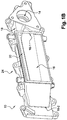
figure 1A est une vue de face - coté faisceau d'échange de chaleur - d'une pièce d'interface selon l'invention - la
figure 1B est vue en perspective de la pièce d'interface de lafigure 1A - la
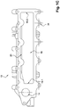
figure 1C est une vue de face - coté culasse du moteur - d'une pièce d'interface selon l'invention - la
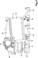
figure 2 est une vue de dessus d'un module d'alimentation en gaz d'un moteur selon l'invention, et, - la
figure 3 est une vue de perspective partiellement écorchée - coté culasse du moteur - du module de lafigure 2 . - La pièce d'interface 10 ferme le volume d'entrée de la culasse et définit un premier passage pour des gaz sortant d'une vanne 50 (décrite plus loin) et un deuxième passage pour des gaz sortant de l'échangeur de chaleur 12.
- Selon l'invention, la première ouverture 14 présente un profil apte à coopérer avec un élément de la vanne comportant une partie mobile (ou actionneur) 52 d'une vanne 50 en vue de l'obturation au moins partielle de la première ouverture 14 par l'élément présentant la partie mobile 52 de la vanne 50.
- Autrement dit, selon l'invention, la première ouverture 14 est apte à recevoir au moins une partie de la vanne 50. La vanne 50 sera dénommée, dans la suite de la description, vanne EGR 50.
- Dans le mode de réalisation illustré ici, l'ouverture est apte à recevoir une chemise accueillant, ici, la partie mobile 52 de la vanne EGR 50. Le profil de la première ouverture 14 correspond donc, ici, au profil de la chemise.
- Un autre mode de réalisation non illustré propose que le profil de la première ouverture 14 soit un siège de soupape. En d'autres termes, dans un tel cas, le profil de la première ouverture 14 est apte à recevoir l'actionneur 52 de la vanne EGR 50.
- Dans ce mode de réalisation, la pièce d'interface 10 comporte en outre un canal de liaison 18, reliant la première ouverture 14 et la deuxième ouverture 16.
- Le canal de liaison 18 permet, en d'autres termes, de faire communiquer les première et deuxième ouvertures de manière à obtenir un mélange des deux gaz (ici de l'air de suralimentation et des gaz d'échappement recirculés).
- Dans ce mode de réalisation, le mélange entre les deux gaz se fera au niveau de la deuxième ouverture 16, le canal de liaison 18 permettant diriger les gaz provenant de la vanne EGR 50 de la première ouverture 14 vers la deuxième ouverture 16.
- Ici, la pièce d'interface 10 comporte en outre un canal d'injection 20.
- Le canal s'injection 20 s'étend entre le canal de liaison 18 et une extrémité distante 16-2 du canal de liaison 18 de la deuxième ouverture 16. Autrement dit, dans ce mode de réalisation, le canal d'injection 20 se déploie le long de la deuxième ouverture 16. Ici, le canal d'injection 20 s'étend sur la totalité de la longueur de la deuxième ouverture 16.
- Dans le mode de réalisation illustré, le canal d'injection 20 se situe dans le prolongement du canal de liaison 18 et il longe la deuxième ouverture 16.
- Autrement dit, ici, les deux canaux 18 et 20 sont confondus de manière à former un canal remplissant les fonctions de liaison entre les deux ouvertures et d'injection du premier gaz dans le deuxième gaz au niveau de la deuxième ouverture 16.
- Encore autrement dit, les gaz d'échappement recirculés ne traversent pas l'échangeur de chaleur 12 et sont introduit dans la pièce d'interface 10 par les deux canaux 18 et 20, la pièce d'interface 10 étant disposée à la sortie du faisceau d'échange de chaleur de l'échangeur de chaleur 12.
- Dans un mode de réalisation particulier, le canal de liaison 18 et le canal d'injection 20 sont réalisés venue de fonderie de la pièce d'interface 10.
- Selon un mode de réalisation particulier, le canal d'injection 20 présente un volume décroissant entre son extrémité située de manière attenante au canal de liaison 18 et son extrémité située de manière attenante à l'extrémité distale 16-2 de la deuxième ouverture 16 du canal de liaison 18.
- Comme plus particulièrement visible à la
figure 3 , le canal de liaison 18 présente, lui aussi, un volume décroissant entre la première ouverture 14 et la deuxième ouverture 16, le volume situé à proximité de la première ouverture 14, c'est-à-dire au début du canal de liaison 18, étant plus important que celui situé à proximité de la deuxième ouverture 16, c'est-à-dire à la fin du canal de liaison 18. - Dans cet exemple, le canal d'injection 20 comporte une pluralité d'orifices débouchant le long de la deuxième ouverture 16 et dans le volume défini par la deuxième ouverture 16. La pluralité d'orifices d'injection 30 permet de définir un rail d'injection pour le premier gaz (soit ici les gaz d'échappement recirculés) dans la deuxième ouverture 16.
- Ici, l'injection des gaz d'échappement recirculés s'effectue de manière perpendiculaire au flux du deuxième gaz (ici, de l'air de suralimentation) qui traverse le faisceau d'échange de l'échangeur de chaleur 12.
- En outre, la première ouverture 14 est bordée par une collerette 22 apte à définir un rebord de fixation pour un corps 54 de la vanne EGR 50.
- La pièce d'interface 10 comporte une périphérie présentant des orifices 24 pour sa liaison à la culasse. Ici, les orifices 24 pour la fixation de la pièce d'interface à la culasse sont disposés au niveau de protubérances disposées au moins à proximité du canal d'injection 20. Les orifices 24 sont aptes à recevoir des moyens de fixation, ici des vis, aptes à fixer l'élément d'interface 10 sur la culasse du moteur.
- Dans le mode de réalisation illustré aux
figures 1A à 1C , les orifices 24 sont situés sur l'ensemble du pourtour de la pièce d'interface 10. - Une variante de réalisation propose que la pièce d'interface 10 comporte en outre un logement pour accueillir un capteur 25 de température et/ou de pression.
- L'invention concerne aussi un ensemble d'une pièce d'interface telle que précédemment décrite et d'une vanne EGR 50.
- La vanne EGR 50 comporte au moins une partie mobile 52 et un corps 54.
- Ici, la partie mobile 52 de la vanne EGR 50 est insérée dans un élément de la vanne réalisé sous la forme d'une chemise. Dans ce mode de réalisation, le corps 54 de la vanne reçoit la chemise comportant la partie mobile 52 de la vanne EGR 50.
La chemise comportant la partie mobile 52 de la vanne EGR 50 est apte à coopérer avec le profil de la première ouverture 14 en vue de l'obturation au moins partielle de la première ouverture 14 par la chemise de la vanne EGR 50.
Autrement dit, ici, la chemise accueillant la partie mobile 52 est apte à fermer au moins en partie le volume de la première ouverture 14 de la pièce d'interface 10.
Dans de mode de réalisation, la partie mobile 52 de la vanne EGR 50 est une soupape.
Le corps 54 de la vanne EGR 50 est muni, à l'extrémité proximale de la pièce d'interface 10, d'une bride fixation apte à coopérer avec la collerette 22 de la pièce d'interface 10 pour la liaison vanne EGR 50 - pièce d'interface 10.
Dans le mode de réalisation illustré ici, la vanne EGR 50 et la pièce d'interface sont munies chacune d'orifices traversant permettant leur liaison par l'intermédiaire de vis. - Le module d'alimentation en gaz comporte en outre l'échangeur de chaleur 12 muni d'un faisceau (non représenté) positionné au moins en partie devant la deuxième ouverture 16 de la pièce d'interface 10. Le faisceau d'échange de chaleur est traversé par de l'air de suralimentation, cet air de suralimentation se mélangeant au niveau de la pièce d'interface 10 avec les gaz d'échappement recirculés injectés par l'intermédiaire des canaux 18 et 20.
Autrement dit, le module d'alimentation en gaz est configuré pour permettre le trajet d'un premier fluide traversant l'échangeur de chaleur 12 (ici, de l'air de suralimentation) et le trajet d'un second fluide (ici, des gaz d'échappement recirculés) traversant la vanne EGR 50 et les deux canaux 18 et 20, les deux fluides se rencontrant et se mélangeant en sortie du faisceau d'échange de chaleur de l'échangeur 12 (ici, au niveau de la pièce d'interface 10 disposé en sortie du faisceau). - Dans ce mode de réalisation, l'échangeur de chaleur 12 comporte un boîtier 26. Le boîtier 26 est assujetti à l'élément d'interface 10, par exemple, par brasage ou soudage.
- Dans le mode de réalisation illustré ici, le boîtier 26 est formé par quatre plaques métalliques, par exemple en aluminium, assemblées les unes aux autres, par exemple, par brasage. Les plaques du boîtier 26 forment une enveloppe comportant quatre faces dites pleines et deux faces dites libres. Les faces libres du boîtier 26 sont situées en face l'une de l'autre.
- Le faisceau d'échange de chaleur (non représenté) est inséré dans le boîtier 26. Ce faisceau pourra, par exemple être réalisé sous la forme d'un empilement de plaques, non représentées, ménageant un passage pour les gaz d'alimentation et un passage pour un fluide caloporteur.
- Ici, une boite collectrice d'entrée (encore appelée boite diffuseur) 28 pour l'air de suralimentation est fixée à une des faces libres du boîtier 26 tandis que la pièce d'interface 10 est fixé à l'autre face libre.
- Le module d'alimentation en gaz comporte, ici, une vanne 60 d'alimentation en gaz apte à orienter lesdits gaz au moins au travers de l'échangeur de chaleur 12.
- Dans ce mode de réalisation, la vanne 60 d'alimentation en gaz apte à orienter lesdits gaz au moins au travers de l'échangeur de chaleur 12 comporte une partie mobile réalisée sous la forme d'un papillon (ou volet). Cette dernière permet de doser la quantité d'air de suralimentation traversant l'échangeur de chaleur 12 et/ou d'étouffer le moteur.
- La vanne 60 d'alimentation en gaz de l'échangeur de chaleur 12 comporte, ici, au moins un corps de vanne et un élément 62 dit élément de sortie 62. Le corps de vanne présente une entrée pour les gaz dans la vanne 60 d'alimentation en gaz de l'échangeur de chaleur 12.
- L'élément de sortie 62 est attaché au corps de vanne de manière à former une première sortie de la vanne d'alimentation 60 vers l'échangeur de chaleur 12. En d'autres termes, l'élément de sortie 62 permet une communication entre la 60 d'alimentation en gaz de l'échangeur de chaleur 12 et l'échangeur de chaleur 12 (et plus particulièrement, entre la vanne d'alimentation 60 et la boite collectrice d'entrée de ce dernier).
- L'invention ne se limite pas aux modes de réalisation décrits ci avant, seulement à titre d'exemples, mais elle englobe toutes les variantes que pourra envisager l'homme de l'art dans le cadre des revendications ci-après. Les variantes décrites précédemment peuvent être prises séparément ou en combinaison les unes avec les autres.
La première ouverture 14 est traversée, dans ce mode de réalisation, par des gaz d'échappement recirculés.
La deuxième ouverture 16, quant à elle et toujours dans le mode de réalisation illustré ici, permet le passage d'un deuxième gaz (ici, de l'air de suralimentation) ayant préalablement traversé le faisceau d'échange de l'échangeur de chaleur 12.
Dans le mode de réalisation illustré, ici, la deuxième ouverture 16 présente une extrémité proximale 16-1 d'un canal de liaison 18 (décrit plus loin) et une extrémité distale 16-2 du canal de liaison 18. L'extrémité distale 16-2 pourra aussi être appelée extrémité distante 16-2 du canal de liaison 18 de la deuxième ouverture 16. La deuxième ouverture 16 présente, en outre, une longueur et une hauteur.
Claims (9)
- Module d'alimentation en gaz d'un moteur de véhicule automobile, comportant :- un échangeur de chaleur (12) d'air de suralimentation muni d'un faisceau,- une pièce d'interface (10) entre une culasse du moteur et l'échangeur de chaleur (12) et,- une vanne (50) comportant un élément comprenant une partie mobile (52),la pièce d'interface (10) comportant :- une première ouverture (14) pour le passage de gaz d'échappement recirculés, ladite première ouverture (14) présentant un profil apte à coopérer avec ledit élément de la vanne (50) en vue de l'obturation au moins partielle de ladite première ouverture (14) par ladite partie mobile (52),- une deuxième ouverture (16) pour le passage d'air de suralimentation venant en regard d'au moins une partie du faisceau de l'échangeur de chaleur (12), et- un canal de liaison (18), ladite première ouverture (14) et ladite deuxième ouverture (16) étant reliées par ledit canal de liaison (18),- un canal d'injection (20) s'étendant entre ledit canal de liaison (18) et une extrémité distante (16-2) dudit canal de liaison (18) de ladite deuxième ouverture (16),le canal d'injection (20) se déployant le long de la deuxième ouverture (16), le canal d'injection (20) s'étendant sur la totalité de la longueur de la deuxième ouverture (16).
- Module selon la revendication 1, ledit canal de liaison (18) et ledit canal d'injection (20) étant réalisés venue de fonderie de ladite pièce d'interface (10).
- Module selon l'une des revendications 1 ou 2, ladite deuxième ouverture (16) présentant une extrémité proximale (16-1) dudit canal de liaison (18) et une extrémité distale (16-2) dudit canal de liaison (18), ledit canal d'injection (20) présentant un volume décroissant entre son extrémité attenante audit canal de liaison (18) et son extrémité attenante à ladite extrémité distale (16-2) dudit canal de liaison (18).
- Module selon l'une des revendications 1 à 3, ledit canal d'injection (20) comportant une pluralité d'orifices (30) débouchant le long de la deuxième ouverture (16).
- Module selon l'une des revendications précédentes, ladite première ouverture (14) étant bordée par une collerette (22) apte à définir un rebord de fixation pour un corps (54) de ladite vanne (50).
- Module selon l'une des revendications précédentes, la pièce d'interface comportant une périphérie présentant des orifices (24) pour la liaison de ladite pièce d'interface (10) à ladite culasse.
- Module selon l'une des revendications précédentes, la pièce d'interface comportant en outre un logement pour accueillir un capteur (25) de température et/ou de pression.
- Module selon l'une quelconque des revendications précédentes, ladite partie mobile (52) étant une soupape et ledit profil de ladite première ouverture (14) correspondant au profil dudit élément comportant ladite soupape.
- Module selon l'une quelconque des revendications précédentes, comportant en outre une vanne d'alimentation en air de suralimentation de manière à orienter l'air de suralimentation au moins au travers dudit échangeur de chaleur (12).
Applications Claiming Priority (2)
| Application Number | Priority Date | Filing Date | Title |
|---|---|---|---|
| FR0906209A FR2954414B1 (fr) | 2009-12-21 | 2009-12-21 | Piece d'interface entre une culasse d'un moteur de vehicule automobile et un echangeur de chaleur. |
| PCT/EP2010/068775 WO2011076539A1 (fr) | 2009-12-21 | 2010-12-02 | Piece d'interface entre une culasse d'un moteur de vehicule automobile et un echangeur de chaleur |
Publications (2)
| Publication Number | Publication Date |
|---|---|
| EP2516822A1 EP2516822A1 (fr) | 2012-10-31 |
| EP2516822B1 true EP2516822B1 (fr) | 2018-02-14 |
Family
ID=42227633
Family Applications (1)
| Application Number | Title | Priority Date | Filing Date |
|---|---|---|---|
| EP10787742.5A Active EP2516822B1 (fr) | 2009-12-21 | 2010-12-02 | Module d'admission en gaz d'un moteur de véhicule automobile comportant un échangeur de chaleur. |
Country Status (6)
| Country | Link |
|---|---|
| US (1) | US9394862B2 (fr) |
| EP (1) | EP2516822B1 (fr) |
| KR (1) | KR101751089B1 (fr) |
| CN (1) | CN102667095B (fr) |
| FR (1) | FR2954414B1 (fr) |
| WO (1) | WO2011076539A1 (fr) |
Families Citing this family (7)
| Publication number | Priority date | Publication date | Assignee | Title |
|---|---|---|---|---|
| FR2933469B1 (fr) * | 2008-07-01 | 2013-01-11 | Valeo Sys Controle Moteur Sas | Ensemble d'un corps de vanne et d'un joint d'etancheite, ensemble d'un corps de vanne,d'un joint d'etancheite et d'une canalisation,joint pour l'ensemble |
| FR2958337B1 (fr) * | 2010-03-31 | 2013-03-01 | Valeo Systemes Thermiques | Collecteur de repartition de gaz dans la culasse d'un moteur, ensemble d'un collecteur de repartition et d'une culasse de moteur. |
| FR2981410B1 (fr) * | 2011-10-12 | 2013-10-18 | Valeo Systemes De Controle Moteur | Module d'alimentation en gaz d'un moteur de vehicule automobile |
| FR3030637B1 (fr) * | 2014-12-22 | 2018-02-16 | Valeo Systemes De Controle Moteur | Module d'alimentation pour moteur a combustion, comportant un canal de refroidissement |
| CN107250502B (zh) * | 2015-02-23 | 2020-04-14 | 日产自动车株式会社 | 内燃机的进气系统配管构造 |
| JP6565381B2 (ja) * | 2015-06-30 | 2019-08-28 | 三菱自動車工業株式会社 | インテークマニホールド |
| KR20180109195A (ko) * | 2017-03-27 | 2018-10-08 | 현대자동차주식회사 | 알루미늄 이지알 쿨러를 구비한 엔진 |
Citations (11)
| Publication number | Priority date | Publication date | Assignee | Title |
|---|---|---|---|---|
| DE10028131C1 (de) | 2000-06-07 | 2001-12-13 | Daimler Chrysler Ag | Abgasrückführsystem für eine Brennkraftmaschine |
| DE10341393B3 (de) | 2003-09-05 | 2004-09-23 | Pierburg Gmbh | Luftansaugkanalsystem für eine Verbrennungskraftmaschine |
| DE102004013309A1 (de) | 2004-03-17 | 2005-10-06 | Mahle Filtersysteme Gmbh | Sauganlage für eine Brennkraftmaschine |
| US20060075997A1 (en) * | 2004-10-08 | 2006-04-13 | Huebler Mark S | Intake manifold for an internal combustion engine |
| DE102004048867A1 (de) | 2004-10-07 | 2006-04-27 | Daimlerchrysler Ag | Wassergekühlte Brennkraftmaschine mit V-förmig angeordneten Zylinderreihen |
| DE102006039497A1 (de) | 2005-08-23 | 2007-03-01 | Detroit Diesel Corp., Detroit | Krümmerkörper für einen Verbrennungsmotor |
| EP1870591A2 (fr) | 2003-11-19 | 2007-12-26 | Mahle Filtersysteme GmbH | Dispositif d'admission pour un moteur à combustion interne |
| WO2008061693A1 (fr) | 2006-11-20 | 2008-05-29 | Valeo Systemes De Controle Moteur | Dispositif d'admission de gaz |
| DE102007040661A1 (de) | 2007-08-27 | 2009-03-05 | Behr Gmbh & Co. Kg | Saugrohr für einen Verbrennungsmotor |
| FR2931517A1 (fr) * | 2008-05-20 | 2009-11-27 | Valeo Sys Controle Moteur Sas | Dispositif d'admission de gaz |
| EP2129888B1 (fr) | 2007-03-23 | 2012-10-31 | Behr GmbH & Co. KG | Module d'aspiration de fluide de charge et moteur à combustion interne |
Family Cites Families (6)
| Publication number | Priority date | Publication date | Assignee | Title |
|---|---|---|---|---|
| JPS51137010A (en) * | 1975-05-22 | 1976-11-26 | Nissan Motor Co Ltd | A multi point ignition engine |
| EP1270924A3 (fr) * | 2001-06-28 | 2004-01-07 | Delphi Technologies, Inc. | Ensemble intégré de collecteur d'admission pour un moteur à combustion interne |
| JP4015528B2 (ja) * | 2002-10-21 | 2007-11-28 | 愛三工業株式会社 | 内燃機関の排気還流装置 |
| US7204240B2 (en) * | 2004-06-12 | 2007-04-17 | Borgwarner Inc. | Integrated valve |
| US7441403B2 (en) * | 2004-12-20 | 2008-10-28 | Detroit Diesel Corporation | Method and system for determining temperature set points in systems having particulate filters with regeneration capabilities |
| KR20070108948A (ko) | 2005-03-08 | 2007-11-13 | 보르그워너 인코퍼레이티드 | 대기 위치를 갖는 egr 밸브 |
-
2009
- 2009-12-21 FR FR0906209A patent/FR2954414B1/fr active Active
-
2010
- 2010-12-02 EP EP10787742.5A patent/EP2516822B1/fr active Active
- 2010-12-02 US US13/516,829 patent/US9394862B2/en active Active
- 2010-12-02 CN CN201080058612.6A patent/CN102667095B/zh active Active
- 2010-12-02 KR KR1020127018500A patent/KR101751089B1/ko not_active Expired - Fee Related
- 2010-12-02 WO PCT/EP2010/068775 patent/WO2011076539A1/fr not_active Ceased
Patent Citations (11)
| Publication number | Priority date | Publication date | Assignee | Title |
|---|---|---|---|---|
| DE10028131C1 (de) | 2000-06-07 | 2001-12-13 | Daimler Chrysler Ag | Abgasrückführsystem für eine Brennkraftmaschine |
| DE10341393B3 (de) | 2003-09-05 | 2004-09-23 | Pierburg Gmbh | Luftansaugkanalsystem für eine Verbrennungskraftmaschine |
| EP1870591A2 (fr) | 2003-11-19 | 2007-12-26 | Mahle Filtersysteme GmbH | Dispositif d'admission pour un moteur à combustion interne |
| DE102004013309A1 (de) | 2004-03-17 | 2005-10-06 | Mahle Filtersysteme Gmbh | Sauganlage für eine Brennkraftmaschine |
| DE102004048867A1 (de) | 2004-10-07 | 2006-04-27 | Daimlerchrysler Ag | Wassergekühlte Brennkraftmaschine mit V-förmig angeordneten Zylinderreihen |
| US20060075997A1 (en) * | 2004-10-08 | 2006-04-13 | Huebler Mark S | Intake manifold for an internal combustion engine |
| DE102006039497A1 (de) | 2005-08-23 | 2007-03-01 | Detroit Diesel Corp., Detroit | Krümmerkörper für einen Verbrennungsmotor |
| WO2008061693A1 (fr) | 2006-11-20 | 2008-05-29 | Valeo Systemes De Controle Moteur | Dispositif d'admission de gaz |
| EP2129888B1 (fr) | 2007-03-23 | 2012-10-31 | Behr GmbH & Co. KG | Module d'aspiration de fluide de charge et moteur à combustion interne |
| DE102007040661A1 (de) | 2007-08-27 | 2009-03-05 | Behr Gmbh & Co. Kg | Saugrohr für einen Verbrennungsmotor |
| FR2931517A1 (fr) * | 2008-05-20 | 2009-11-27 | Valeo Sys Controle Moteur Sas | Dispositif d'admission de gaz |
Also Published As
| Publication number | Publication date |
|---|---|
| FR2954414A1 (fr) | 2011-06-24 |
| WO2011076539A1 (fr) | 2011-06-30 |
| FR2954414B1 (fr) | 2013-09-13 |
| CN102667095B (zh) | 2015-10-21 |
| KR20120115319A (ko) | 2012-10-17 |
| US9394862B2 (en) | 2016-07-19 |
| CN102667095A (zh) | 2012-09-12 |
| US20120298066A1 (en) | 2012-11-29 |
| EP2516822A1 (fr) | 2012-10-31 |
| KR101751089B1 (ko) | 2017-06-26 |
Similar Documents
| Publication | Publication Date | Title |
|---|---|---|
| EP2504556B1 (fr) | Module d'alimentation en gaz d'un moteur de vehicule automobile, ensemble d'une culasse d'un moteur et d'un tel module, et moteur de vehicule automobile comportant un tel ensemble | |
| EP2516822B1 (fr) | Module d'admission en gaz d'un moteur de véhicule automobile comportant un échangeur de chaleur. | |
| FR2938051A1 (fr) | Unite d'echange thermique a usage par exemple dans un circuit de recirculation de gaz d'echappement | |
| WO2003102396A1 (fr) | Module d'echange de chaleur conforme pour envelopper un moteur de vehicule automobile | |
| FR2856746A1 (fr) | Module de refroidissement de l'air de suralimentation et des gaz recircules d'un moteur a combustion interne de vehicule automobile | |
| FR2908832A1 (fr) | Carter pour echangeur de chaleur | |
| EP1983171A1 (fr) | Echangeur de chaleur pour véhicule automobile | |
| EP2469067B1 (fr) | Carter pour module d'admission, notamment pour module d'admission de moteur thermique de véhicule automobile, et module d'admission comprenant un tel carter | |
| WO2016097566A1 (fr) | Vanne comportant des moyens d'actionnement entre deux conduits d'entrée | |
| FR2983533A1 (fr) | Dispositif de regulation thermique de l'air d'admission d'un moteur a combustion interne d'un vehicule automobile et vehicule automobile comprenant un tel dispositif | |
| WO2011076538A1 (fr) | Module d'alimentation en gaz d'un moteur de vehicule automobile, ensemble d'une culasse d'un moteur et d'un tel module et moteur thermique comportant un tel ensemble | |
| FR2721349A1 (fr) | Moteur à combustion interne à recirculation des gaz d'échappement. | |
| FR2930022A1 (fr) | Echangeur de chaleur pour vehicule automobile | |
| EP3803093A1 (fr) | Répartiteur d'admission pour moteur thermique avec dispositif de melange optimisé de gaz recirculés | |
| EP3561282B1 (fr) | Moteur à combustion interne avec plaque de fermeture d'une face de distribution | |
| FR2915274A1 (fr) | Echangeur de chaleur pour vehicule automobile | |
| EP3550120A1 (fr) | Module d'admission double flux de moteur thermique | |
| FR2906574A1 (fr) | Dispositif de recirculation des gaz d'echappement d'un moteur a combustion interne et moteur a combustion interne equipe d'un tel dispositif | |
| FR2879518A1 (fr) | Agencement de conduit d'admission d'air d'un moteur a combustion interne | |
| FR3049981A1 (fr) | Moteur a combustion interne comportant une conduite de redirection des gaz d'echappement integree a la culasse | |
| FR3062173A1 (fr) | Moteur comprenant une ligne d'alimentation en gaz d'admission pourvu d'au moins un echangeur thermique | |
| WO2019145212A1 (fr) | Circuit d'admission d'air optimisee d'un groupe motopropulseur de vehicule | |
| FR2961860A1 (fr) | Raccord pour la jonction des gaz d'echappement et de l'air d'admission a l'entree du repartiteur du collecteur d'admission d'un moteur thermique. | |
| FR2969271A1 (fr) | Boitier d'echangeur de chaleur, echangeur de chaleur muni d'un tel boitier et module d'admission equipe d'un tel echangeur | |
| FR2979953A1 (fr) | Culasse pour un moteur a combustion interne et moteur et vehicule comportant une telle culasse |
Legal Events
| Date | Code | Title | Description |
|---|---|---|---|
| PUAI | Public reference made under article 153(3) epc to a published international application that has entered the european phase |
Free format text: ORIGINAL CODE: 0009012 |
|
| 17P | Request for examination filed |
Effective date: 20120723 |
|
| AK | Designated contracting states |
Kind code of ref document: A1 Designated state(s): AL AT BE BG CH CY CZ DE DK EE ES FI FR GB GR HR HU IE IS IT LI LT LU LV MC MK MT NL NO PL PT RO RS SE SI SK SM TR |
|
| DAX | Request for extension of the european patent (deleted) | ||
| 17Q | First examination report despatched |
Effective date: 20141222 |
|
| STAA | Information on the status of an ep patent application or granted ep patent |
Free format text: STATUS: EXAMINATION IS IN PROGRESS |
|
| REG | Reference to a national code |
Ref country code: DE Ref legal event code: R079 Ref document number: 602010048501 Country of ref document: DE Free format text: PREVIOUS MAIN CLASS: F02B0029040000 Ipc: F02M0035100000 |
|
| RIC1 | Information provided on ipc code assigned before grant |
Ipc: F02M 35/10 20060101AFI20170720BHEP Ipc: F02M 26/00 20160101ALI20170720BHEP Ipc: F02M 26/51 20160101ALI20170720BHEP Ipc: F02M 26/21 20160101ALI20170720BHEP Ipc: F02B 29/04 20060101ALI20170720BHEP |
|
| GRAP | Despatch of communication of intention to grant a patent |
Free format text: ORIGINAL CODE: EPIDOSNIGR1 |
|
| STAA | Information on the status of an ep patent application or granted ep patent |
Free format text: STATUS: GRANT OF PATENT IS INTENDED |
|
| INTG | Intention to grant announced |
Effective date: 20170906 |
|
| GRAS | Grant fee paid |
Free format text: ORIGINAL CODE: EPIDOSNIGR3 |
|
| GRAA | (expected) grant |
Free format text: ORIGINAL CODE: 0009210 |
|
| STAA | Information on the status of an ep patent application or granted ep patent |
Free format text: STATUS: THE PATENT HAS BEEN GRANTED |
|
| AK | Designated contracting states |
Kind code of ref document: B1 Designated state(s): AL AT BE BG CH CY CZ DE DK EE ES FI FR GB GR HR HU IE IS IT LI LT LU LV MC MK MT NL NO PL PT RO RS SE SI SK SM TR |
|
| REG | Reference to a national code |
Ref country code: GB Ref legal event code: FG4D Free format text: NOT ENGLISH |
|
| REG | Reference to a national code |
Ref country code: CH Ref legal event code: EP |
|
| REG | Reference to a national code |
Ref country code: IE Ref legal event code: FG4D Free format text: LANGUAGE OF EP DOCUMENT: FRENCH |
|
| REG | Reference to a national code |
Ref country code: DE Ref legal event code: R096 Ref document number: 602010048501 Country of ref document: DE Ref country code: AT Ref legal event code: REF Ref document number: 970003 Country of ref document: AT Kind code of ref document: T Effective date: 20180315 |
|
| REG | Reference to a national code |
Ref country code: NL Ref legal event code: MP Effective date: 20180214 |
|
| REG | Reference to a national code |
Ref country code: AT Ref legal event code: MK05 Ref document number: 970003 Country of ref document: AT Kind code of ref document: T Effective date: 20180214 |
|
| PG25 | Lapsed in a contracting state [announced via postgrant information from national office to epo] |
Ref country code: FI Free format text: LAPSE BECAUSE OF FAILURE TO SUBMIT A TRANSLATION OF THE DESCRIPTION OR TO PAY THE FEE WITHIN THE PRESCRIBED TIME-LIMIT Effective date: 20180214 Ref country code: NO Free format text: LAPSE BECAUSE OF FAILURE TO SUBMIT A TRANSLATION OF THE DESCRIPTION OR TO PAY THE FEE WITHIN THE PRESCRIBED TIME-LIMIT Effective date: 20180514 Ref country code: CY Free format text: LAPSE BECAUSE OF FAILURE TO SUBMIT A TRANSLATION OF THE DESCRIPTION OR TO PAY THE FEE WITHIN THE PRESCRIBED TIME-LIMIT Effective date: 20180214 Ref country code: NL Free format text: LAPSE BECAUSE OF FAILURE TO SUBMIT A TRANSLATION OF THE DESCRIPTION OR TO PAY THE FEE WITHIN THE PRESCRIBED TIME-LIMIT Effective date: 20180214 Ref country code: LT Free format text: LAPSE BECAUSE OF FAILURE TO SUBMIT A TRANSLATION OF THE DESCRIPTION OR TO PAY THE FEE WITHIN THE PRESCRIBED TIME-LIMIT Effective date: 20180214 Ref country code: HR Free format text: LAPSE BECAUSE OF FAILURE TO SUBMIT A TRANSLATION OF THE DESCRIPTION OR TO PAY THE FEE WITHIN THE PRESCRIBED TIME-LIMIT Effective date: 20180214 Ref country code: ES Free format text: LAPSE BECAUSE OF FAILURE TO SUBMIT A TRANSLATION OF THE DESCRIPTION OR TO PAY THE FEE WITHIN THE PRESCRIBED TIME-LIMIT Effective date: 20180214 |
|
| PG25 | Lapsed in a contracting state [announced via postgrant information from national office to epo] |
Ref country code: BG Free format text: LAPSE BECAUSE OF FAILURE TO SUBMIT A TRANSLATION OF THE DESCRIPTION OR TO PAY THE FEE WITHIN THE PRESCRIBED TIME-LIMIT Effective date: 20180514 Ref country code: GR Free format text: LAPSE BECAUSE OF FAILURE TO SUBMIT A TRANSLATION OF THE DESCRIPTION OR TO PAY THE FEE WITHIN THE PRESCRIBED TIME-LIMIT Effective date: 20180515 Ref country code: RS Free format text: LAPSE BECAUSE OF FAILURE TO SUBMIT A TRANSLATION OF THE DESCRIPTION OR TO PAY THE FEE WITHIN THE PRESCRIBED TIME-LIMIT Effective date: 20180214 Ref country code: AT Free format text: LAPSE BECAUSE OF FAILURE TO SUBMIT A TRANSLATION OF THE DESCRIPTION OR TO PAY THE FEE WITHIN THE PRESCRIBED TIME-LIMIT Effective date: 20180214 Ref country code: SE Free format text: LAPSE BECAUSE OF FAILURE TO SUBMIT A TRANSLATION OF THE DESCRIPTION OR TO PAY THE FEE WITHIN THE PRESCRIBED TIME-LIMIT Effective date: 20180214 Ref country code: LV Free format text: LAPSE BECAUSE OF FAILURE TO SUBMIT A TRANSLATION OF THE DESCRIPTION OR TO PAY THE FEE WITHIN THE PRESCRIBED TIME-LIMIT Effective date: 20180214 |
|
| PG25 | Lapsed in a contracting state [announced via postgrant information from national office to epo] |
Ref country code: MT Free format text: LAPSE BECAUSE OF FAILURE TO SUBMIT A TRANSLATION OF THE DESCRIPTION OR TO PAY THE FEE WITHIN THE PRESCRIBED TIME-LIMIT Effective date: 20180214 |
|
| PG25 | Lapsed in a contracting state [announced via postgrant information from national office to epo] |
Ref country code: PL Free format text: LAPSE BECAUSE OF FAILURE TO SUBMIT A TRANSLATION OF THE DESCRIPTION OR TO PAY THE FEE WITHIN THE PRESCRIBED TIME-LIMIT Effective date: 20180214 Ref country code: EE Free format text: LAPSE BECAUSE OF FAILURE TO SUBMIT A TRANSLATION OF THE DESCRIPTION OR TO PAY THE FEE WITHIN THE PRESCRIBED TIME-LIMIT Effective date: 20180214 Ref country code: RO Free format text: LAPSE BECAUSE OF FAILURE TO SUBMIT A TRANSLATION OF THE DESCRIPTION OR TO PAY THE FEE WITHIN THE PRESCRIBED TIME-LIMIT Effective date: 20180214 Ref country code: IT Free format text: LAPSE BECAUSE OF FAILURE TO SUBMIT A TRANSLATION OF THE DESCRIPTION OR TO PAY THE FEE WITHIN THE PRESCRIBED TIME-LIMIT Effective date: 20180214 Ref country code: AL Free format text: LAPSE BECAUSE OF FAILURE TO SUBMIT A TRANSLATION OF THE DESCRIPTION OR TO PAY THE FEE WITHIN THE PRESCRIBED TIME-LIMIT Effective date: 20180214 |
|
| REG | Reference to a national code |
Ref country code: DE Ref legal event code: R026 Ref document number: 602010048501 Country of ref document: DE |
|
| PLBI | Opposition filed |
Free format text: ORIGINAL CODE: 0009260 |
|
| PLAX | Notice of opposition and request to file observation + time limit sent |
Free format text: ORIGINAL CODE: EPIDOSNOBS2 |
|
| PG25 | Lapsed in a contracting state [announced via postgrant information from national office to epo] |
Ref country code: SK Free format text: LAPSE BECAUSE OF FAILURE TO SUBMIT A TRANSLATION OF THE DESCRIPTION OR TO PAY THE FEE WITHIN THE PRESCRIBED TIME-LIMIT Effective date: 20180214 Ref country code: DK Free format text: LAPSE BECAUSE OF FAILURE TO SUBMIT A TRANSLATION OF THE DESCRIPTION OR TO PAY THE FEE WITHIN THE PRESCRIBED TIME-LIMIT Effective date: 20180214 Ref country code: SM Free format text: LAPSE BECAUSE OF FAILURE TO SUBMIT A TRANSLATION OF THE DESCRIPTION OR TO PAY THE FEE WITHIN THE PRESCRIBED TIME-LIMIT Effective date: 20180214 Ref country code: CZ Free format text: LAPSE BECAUSE OF FAILURE TO SUBMIT A TRANSLATION OF THE DESCRIPTION OR TO PAY THE FEE WITHIN THE PRESCRIBED TIME-LIMIT Effective date: 20180214 |
|
| 26 | Opposition filed |
Opponent name: MAHLE INTERNATIONAL GMBH Effective date: 20181112 |
|
| PG25 | Lapsed in a contracting state [announced via postgrant information from national office to epo] |
Ref country code: SI Free format text: LAPSE BECAUSE OF FAILURE TO SUBMIT A TRANSLATION OF THE DESCRIPTION OR TO PAY THE FEE WITHIN THE PRESCRIBED TIME-LIMIT Effective date: 20180214 |
|
| PLBB | Reply of patent proprietor to notice(s) of opposition received |
Free format text: ORIGINAL CODE: EPIDOSNOBS3 |
|
| REG | Reference to a national code |
Ref country code: CH Ref legal event code: PL |
|
| GBPC | Gb: european patent ceased through non-payment of renewal fee |
Effective date: 20181202 |
|
| PG25 | Lapsed in a contracting state [announced via postgrant information from national office to epo] |
Ref country code: LU Free format text: LAPSE BECAUSE OF NON-PAYMENT OF DUE FEES Effective date: 20181202 Ref country code: MC Free format text: LAPSE BECAUSE OF FAILURE TO SUBMIT A TRANSLATION OF THE DESCRIPTION OR TO PAY THE FEE WITHIN THE PRESCRIBED TIME-LIMIT Effective date: 20180214 |
|
| REG | Reference to a national code |
Ref country code: IE Ref legal event code: MM4A |
|
| REG | Reference to a national code |
Ref country code: BE Ref legal event code: MM Effective date: 20181231 |
|
| PG25 | Lapsed in a contracting state [announced via postgrant information from national office to epo] |
Ref country code: IE Free format text: LAPSE BECAUSE OF NON-PAYMENT OF DUE FEES Effective date: 20181202 |
|
| PG25 | Lapsed in a contracting state [announced via postgrant information from national office to epo] |
Ref country code: BE Free format text: LAPSE BECAUSE OF NON-PAYMENT OF DUE FEES Effective date: 20181231 |
|
| PG25 | Lapsed in a contracting state [announced via postgrant information from national office to epo] |
Ref country code: CH Free format text: LAPSE BECAUSE OF NON-PAYMENT OF DUE FEES Effective date: 20181231 Ref country code: GB Free format text: LAPSE BECAUSE OF NON-PAYMENT OF DUE FEES Effective date: 20181202 Ref country code: LI Free format text: LAPSE BECAUSE OF NON-PAYMENT OF DUE FEES Effective date: 20181231 |
|
| PG25 | Lapsed in a contracting state [announced via postgrant information from national office to epo] |
Ref country code: TR Free format text: LAPSE BECAUSE OF FAILURE TO SUBMIT A TRANSLATION OF THE DESCRIPTION OR TO PAY THE FEE WITHIN THE PRESCRIBED TIME-LIMIT Effective date: 20180214 |
|
| PG25 | Lapsed in a contracting state [announced via postgrant information from national office to epo] |
Ref country code: PT Free format text: LAPSE BECAUSE OF FAILURE TO SUBMIT A TRANSLATION OF THE DESCRIPTION OR TO PAY THE FEE WITHIN THE PRESCRIBED TIME-LIMIT Effective date: 20180214 |
|
| PG25 | Lapsed in a contracting state [announced via postgrant information from national office to epo] |
Ref country code: HU Free format text: LAPSE BECAUSE OF FAILURE TO SUBMIT A TRANSLATION OF THE DESCRIPTION OR TO PAY THE FEE WITHIN THE PRESCRIBED TIME-LIMIT; INVALID AB INITIO Effective date: 20101202 Ref country code: MK Free format text: LAPSE BECAUSE OF NON-PAYMENT OF DUE FEES Effective date: 20180214 |
|
| PG25 | Lapsed in a contracting state [announced via postgrant information from national office to epo] |
Ref country code: IS Free format text: LAPSE BECAUSE OF FAILURE TO SUBMIT A TRANSLATION OF THE DESCRIPTION OR TO PAY THE FEE WITHIN THE PRESCRIBED TIME-LIMIT Effective date: 20180614 |
|
| PLCK | Communication despatched that opposition was rejected |
Free format text: ORIGINAL CODE: EPIDOSNREJ1 |
|
| APAH | Appeal reference modified |
Free format text: ORIGINAL CODE: EPIDOSCREFNO |
|
| APBM | Appeal reference recorded |
Free format text: ORIGINAL CODE: EPIDOSNREFNO |
|
| APBP | Date of receipt of notice of appeal recorded |
Free format text: ORIGINAL CODE: EPIDOSNNOA2O |
|
| APBQ | Date of receipt of statement of grounds of appeal recorded |
Free format text: ORIGINAL CODE: EPIDOSNNOA3O |
|
| P01 | Opt-out of the competence of the unified patent court (upc) registered |
Effective date: 20230603 |
|
| REG | Reference to a national code |
Ref country code: DE Ref legal event code: R100 Ref document number: 602010048501 Country of ref document: DE |
|
| APBU | Appeal procedure closed |
Free format text: ORIGINAL CODE: EPIDOSNNOA9O |
|
| PLBN | Opposition rejected |
Free format text: ORIGINAL CODE: 0009273 |
|
| STAA | Information on the status of an ep patent application or granted ep patent |
Free format text: STATUS: OPPOSITION REJECTED |
|
| 27O | Opposition rejected |
Effective date: 20231013 |
|
| PGFP | Annual fee paid to national office [announced via postgrant information from national office to epo] |
Ref country code: DE Payment date: 20241211 Year of fee payment: 15 |
|
| PGFP | Annual fee paid to national office [announced via postgrant information from national office to epo] |
Ref country code: FR Payment date: 20251230 Year of fee payment: 16 |