EP2515727B1 - Infusion unit for drinks with washing system - Google Patents
Infusion unit for drinks with washing system Download PDFInfo
- Publication number
- EP2515727B1 EP2515727B1 EP10812927.1A EP10812927A EP2515727B1 EP 2515727 B1 EP2515727 B1 EP 2515727B1 EP 10812927 A EP10812927 A EP 10812927A EP 2515727 B1 EP2515727 B1 EP 2515727B1
- Authority
- EP
- European Patent Office
- Prior art keywords
- infusion
- hot water
- moving element
- seat
- infusion unit
- Prior art date
- Legal status (The legal status is an assumption and is not a legal conclusion. Google has not performed a legal analysis and makes no representation as to the accuracy of the status listed.)
- Active
Links
- 238000001802 infusion Methods 0.000 title claims description 86
- 238000005406 washing Methods 0.000 title claims description 31
- XLYOFNOQVPJJNP-UHFFFAOYSA-N water Substances O XLYOFNOQVPJJNP-UHFFFAOYSA-N 0.000 claims description 67
- 239000002775 capsule Substances 0.000 claims description 57
- 235000013361 beverage Nutrition 0.000 claims description 37
- 235000013353 coffee beverage Nutrition 0.000 claims description 20
- 239000004615 ingredient Substances 0.000 claims description 18
- 238000007789 sealing Methods 0.000 claims 1
- 230000006835 compression Effects 0.000 description 6
- 238000007906 compression Methods 0.000 description 6
- 239000000843 powder Substances 0.000 description 6
- 235000015114 espresso Nutrition 0.000 description 4
- 239000000796 flavoring agent Substances 0.000 description 3
- 235000019634 flavors Nutrition 0.000 description 3
- 238000004891 communication Methods 0.000 description 2
- 238000007599 discharging Methods 0.000 description 2
- 230000000694 effects Effects 0.000 description 2
- 238000000605 extraction Methods 0.000 description 2
- 230000004913 activation Effects 0.000 description 1
- 235000019568 aromas Nutrition 0.000 description 1
- 238000005452 bending Methods 0.000 description 1
- 235000013305 food Nutrition 0.000 description 1
- 238000010438 heat treatment Methods 0.000 description 1
- 239000007788 liquid Substances 0.000 description 1
- 238000004519 manufacturing process Methods 0.000 description 1
- 239000000463 material Substances 0.000 description 1
- 238000010137 moulding (plastic) Methods 0.000 description 1
Images


Classifications
-
- A—HUMAN NECESSITIES
- A47—FURNITURE; DOMESTIC ARTICLES OR APPLIANCES; COFFEE MILLS; SPICE MILLS; SUCTION CLEANERS IN GENERAL
- A47J—KITCHEN EQUIPMENT; COFFEE MILLS; SPICE MILLS; APPARATUS FOR MAKING BEVERAGES
- A47J31/00—Apparatus for making beverages
- A47J31/44—Parts or details or accessories of beverage-making apparatus
- A47J31/60—Cleaning devices
-
- A—HUMAN NECESSITIES
- A47—FURNITURE; DOMESTIC ARTICLES OR APPLIANCES; COFFEE MILLS; SPICE MILLS; SUCTION CLEANERS IN GENERAL
- A47J—KITCHEN EQUIPMENT; COFFEE MILLS; SPICE MILLS; APPARATUS FOR MAKING BEVERAGES
- A47J31/00—Apparatus for making beverages
- A47J31/24—Coffee-making apparatus in which hot water is passed through the filter under pressure, i.e. in which the coffee grounds are extracted under pressure
- A47J31/34—Coffee-making apparatus in which hot water is passed through the filter under pressure, i.e. in which the coffee grounds are extracted under pressure with hot water under liquid pressure
- A47J31/36—Coffee-making apparatus in which hot water is passed through the filter under pressure, i.e. in which the coffee grounds are extracted under pressure with hot water under liquid pressure with mechanical pressure-producing means
- A47J31/3666—Coffee-making apparatus in which hot water is passed through the filter under pressure, i.e. in which the coffee grounds are extracted under pressure with hot water under liquid pressure with mechanical pressure-producing means whereby the loading of the brewing chamber with the brewing material is performed by the user
- A47J31/3676—Cartridges being employed
- A47J31/368—Permeable cartridges being employed
- A47J31/3685—Brewing heads therefor
-
- A—HUMAN NECESSITIES
- A47—FURNITURE; DOMESTIC ARTICLES OR APPLIANCES; COFFEE MILLS; SPICE MILLS; SUCTION CLEANERS IN GENERAL
- A47J—KITCHEN EQUIPMENT; COFFEE MILLS; SPICE MILLS; APPARATUS FOR MAKING BEVERAGES
- A47J31/00—Apparatus for making beverages
- A47J31/44—Parts or details or accessories of beverage-making apparatus
- A47J31/4403—Constructional details
- A47J31/446—Filter holding means; Attachment of filters to beverage-making apparatus
- A47J31/4467—Filter holding means; Attachment of filters to beverage-making apparatus by means of linear guides, e.g. drawer-type engagement
Definitions
- the present invention relates to improvements to machines for making beverages, in particular but not exclusively for making espresso coffee, and to the infusion units built in said machines.
- machines for making beverages in particular for machines for making coffee such as espresso coffee or the like, of the automatic or semi-automatic type, for household or professional use, which use single-dose coffee capsules or other ingredients for making beverages, or loose products that are first inserted into a filter or cup that is then placed into an infusion unit.
- machines for making coffee such as espresso coffee or the like
- automatic or semi-automatic type for household or professional use, which use single-dose coffee capsules or other ingredients for making beverages, or loose products that are first inserted into a filter or cup that is then placed into an infusion unit.
- WO-A-2009/069167 describes an infusion unit for making coffee, comprising a sliding drawer, forming a moving element with a seat for single-dose capsules containing coffee powder or other ingredients for making a beverage, in particular espresso coffee.
- the moving element can shift from a loading position of the capsules to an infusion position, wherein the capsule seat is interposed between a hot water dispensing device and a beverage outlet nozzle, opposite to each other.
- an accessory is usually provided which consists of a sort of mock capsule that is manually inserted into the seat and used in replacement of a real capsule to carry out one or more washing cycles with hot water under pressure. By flowing through this washing capsule, the water crosses the beverage dispensing circuit removing any scrap or deposits.
- Some coffee machines in particular in machines using infusion capsules containing coffee powders, which are inserted in a drawer system of the type described above, exhibit a system for closing the infusion chamber of the hydraulic type.
- An example of this infusion unit with hydraulic closure of the infusion chamber is described in WO2009/093202 .
- the piston also comprises a water heating system and is removably constrained to a stem stiffly connected to a hydraulic piston sliding in a hydraulic cylinder forming a cylinder/piston actuator with the above hydraulic piston.
- This system is particularly complex and expensive to manufacture.
- the invention aims at totally or partly overcoming one or more of the drawbacks of the prior art.
- the invention provides an infusion unit of the type described above, with a moving element or drawer fitted with a seat for single-dose capsules of doses of loose ingredients for making coffee or other beverage, a simpler and easier washing of the beverage dispensing circuit.
- the infusion unit provides for the moving element to integrally carry, that is, constrained thereto, a washing member which (through the movement of the moving element) may be positioned between the hot water dispensing device and the beverage outlet nozzle for forming a washing channel, wherethrough the water dispensed by the hot water dispensing device flows towards the beverage outlet nozzle.
- a washing member which (through the movement of the moving element) may be positioned between the hot water dispensing device and the beverage outlet nozzle for forming a washing channel, wherethrough the water dispensed by the hot water dispensing device flows towards the beverage outlet nozzle.
- the washing operations of the infusion unit are greatly simplified and the risk of losing the washing accessories normally provided in traditional machines is prevented.
- the moving element may be configured for taking two positions only, the extracted or charging position coinciding with the washing position.
- the infusion unit is made for handling single-dose capsules, for example made of a plastic material or the like, which contain coffee powder or other ingredients for making the beverage.
- the concepts at the basis of the invention may advantageously be used also in machines and infusion units wherein the ingredients are inserted into the machine in a different manner, for example placing them into a cup or filter, that is, in a containment member provided with a pierced wall that allows the outflow of the beverage or other food product obtained by extracting the flavours from the ingredients with hot water under pressure.
- the invention also relates to a coffee machine comprising an infusion unit of the type defined above.
- Fig. 12 globally indicates a coffee machine 1, wherein an infusion unit according to the invention is built in, as shall be better described hereinafter in Figs. 1 to 10 .
- Machine 1 comprises, in a per se known manner, a water tank, a pump for feeding the water to a boiler, wherefrom the hot water under pressure is fed to the infusion unit, described hereinafter.
- the water fed by the pump is also used for closing the infusion unit, as shall be better described hereinafter.
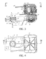
- the infusion unit globally indicated with 3, comprises a bearing structure 5 defining side guides 7 for the sliding (according to the double arrow f9) of a moving element or unit globally indicated with 9.
- the moving element 9 is substantially configured as a drawer sliding along guides 7 and substantially exhibits a frame with a substantially rectangular development 11 with a wide window or central opening 13 that extends longitudinally in the direction of arrow f9.
- the trajectory performed by the moving element 9 is inclined relative to the horizontal for the purposes that shall be explained hereinafter.
- the moving element 9 carries a seat 15 for receiving single-dose capsules C of coffee powder for making espresso coffee or similar beverages.
- seat 15 is delimited on the one side by a wall 15A, with circa semi-cylindrical development, and on the opposite side by a pair of oscillating arms 15B hinged in 17 to the moving element 9.
- the inside surfaces of the oscillating arms 15B and the inside surface of wall 15A laterally delimit an infusion chamber whose shape corresponds to the shape of the single-dose capsule C.
- the infusion chamber is completed and closed at the top and at the bottom by mechanical components described hereinafter, so as to define a closed volume wherethrough hot water under pressure is made to flow to extract the flavours contained in the single-dose capsule C.
- the moving element 9 is fixed to a washing member globally indicated with 19.
- the washing member 19 exhibits a substantially cylindrical body 21 having a top face 21A and a bottom face 21B.
- an annular seat is made on the top face 21A for a seal 23A, whereas an annular seat is made on the bottom face for a bottom seal 23B, for the purposes described hereinafter.
- a conduit 25 develops through the substantially cylindrical body 21 of the washing member 19 that crosses the entire body 21 and is open on the top face 21A and on the bottom face 21B and more exactly at respective lowered zones made on said two top 21A and bottom 21B faces.
- Body 21 of the washing member 19 is steadily constrained to the moving member 9 to move therewith.
- the constraint between body 21 of the washing member 19 and the moving member 9 comprises an elastic element, for example an elastic sheet 27.
- this elastic sheet 27 is formed integrally, with body 21 and with the moving element 9 or more exactly with frame 11 that is the main part thereof. This allows making the device with a simple plastic moulding operation.
- the elastic sheet 27 acts as laminar spring and allows a movement of body 21 of the washing member 19 in a direction substantially orthogonal to direction f9 of movement of the moving member 9 for the purposes described hereinafter.
- structure 5 exhibits a discharge opening 31 with a discharge hopper 33 developing downwards to discharge the spent capsules C.
- a collecting container may be positioned underneath the discharge opening 31. Adjacent the discharge opening 31 structure 5 carries an outlet nozzle of the beverage, globally indicated with 35. The nozzle may be fitted with two side spouts that allow dispensing the coffee or other beverage in one or two cups located one adjacent the other on a plane 1A ( Fig. 12 ) machine 1 is provided with.
- nozzle 35 for the beverage outlet is fitted with an outlet opening 37, preferably closed by a counter pressure valve 39 comprising for example a gate and an elastic member, in the example shown formed by a compression spring.
- the counter pressure valve 39 opens when the pressure of the infusion water in capsule C has reached a certain value, the valve being calibrated for obtaining particular organoleptic features of the drink.
- Structure 5 carries, in a position overlying and opposite the outlet nozzle 35 of the beverage, a hot water dispensing device 41.
- the dispensing device 41 exhibits a hydraulic closing system of the infusion chamber, as shown in the drawing.
- the hot water dispensing device may be made in a different way and have for example a mechanical closing system.
- the hot water dispensing device has no piercer, as it uses capsules C that need not be pierced.
- the hot water dispensing device 41 may be provided with a top piercer to pierce capsules C at the top. In the example shown there is provided a bottom piercer to pierce the bottom surface in capsules C.
- the hot water dispensing device 41 comprises a cylinder-piston actuator the cylinder whereof consists at least partly of a liner 43 seated in a seat 45 and locked therein by a closing flange 46.
- Liner 43 has a top closing wall 43A wherein a port 43B for feeding water under pressure opens.
- Port 43B is in connection with a chamber 43C wherein a first conduit 48 leads that feeds water under pressure fed by a pump, as shall be described hereinafter with reference to the schematic representation of the hydraulic circuit Fig. 11 .
- a piston 47 slides fitted with an annular seal 49 and at the top forming a pressure surface 47A.
- Piston 47 also forms a collar 47B, surrounding a main body 47C of piston 47.
- elastic members acting on the piston with a force opposite the force exerted by the water under pressure fed through conduit 48.
- the elastic members are formed by compression springs 51 arranged about the axis of piston 47 in a suitable number, for example three or four. Springs 51 are compressed between collar 47B of piston 47 and flange 46 constrained to seat 45.
- body 47C of piston 47 is integral to a block 53 forming a chamber 55 for feeding hot water under pressure.
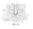
- Chamber 55 is in connection with a conduit 57 for feeding hot water under pressure coming from the boiler machine 1 is fitted with and that shall be described briefly with reference to Fig. 11 .
- the hot water reaches a dispensing opening 53B ( Fig. 13 ) made on a bottom surface 53A of block 53, which forms a closing surface of the infusion chamber.
- chamber 55 for feeding the hot water and the dispensing opening 53B made on surface 53A of block 53 are in flow communication through a port 55A ( Fig. 13 ) that is closed by a calibrated valve 61.
- the latter comprises a gate 63 elastically stressed by an elastic member, for example a helical compression spring 65 seated, along with gate 63, within a sliding seat formed in body 47C of piston 47.
- This calibrated valve 63 allows the proper operation of the hot water dispensing device 41 as shall be better clarified hereinafter with reference to the dispensing cycle.
- a channel 56 extends between opening 53B and port 55A visible in the section of Fig. 13 , wherethrough the hot water under pressure flows when it has reached an opening pressure of the calibrated valve 61.
- the block formed by flange 46 and by seat 45 is fixed relative to structure 5 and an elastic element 67 is constrained thereto, for example formed by a shaped elastic sheet having the function of ejecting capsule C from seat 15.
- Fig. 1 shows the position that the infusion unit takes when a new capsule C is charged into seat 15.
- the moving element or sliding drawer 9 is in a charging position, so as to be accessible to the user from outside machine 1. In this way it is easy to insert capsule C into the seat formed between the oscillating arms 15B and the fixed wall 15A constrained to the moving element 9.
- the moving element or drawer 9 is pushed within the machine up to moving seat 15 in alignment with the hot water dispensing device 41 and with the beverage outlet nozzle 35.
- capsule C is arranged with its bottom in contact with a disc 69 defining the bottom wall of the infusion chamber, the side walls thereof are formed by arms 15B and by wall 15A.
- capsule C has been brought to its infusion position ( Fig. 3 ) going beyond the elastic element 67 which in rest condition, is at a lower height than the top flange CF of capsule C in infusion position. This is made possible by the elasticity of the elastic element 67 and by the chamfered shape thereof that allows, under the effect of the thrust given by the moving element 9, the lifting of the elastic movement 67 and the overtaking of the latter by capsule C.
- the hot water dispensing device 41 is actuated feeding water under pressure in the cylinder formed by liner 43.
- the compression pushes wall 47A of piston 47 downwards causing the compression of springs 51 and thus the lowering of surface 53A against the top surface of capsule C in this way defining the top closing wall of the infusion chamber.
- the latter therefore remains formed by the bottom closing wall or surface 53A constrained to piston 47, by arms 15B, by wall 15A and by the wall formed by disc 69 associated to the drink outlet nozzle 35.
- the hot water under pressure fed through conduit 57 acts on the calibrated valve 61 to cause the opening thereof through the compression of spring 65 and upwards sliding of the cursor or gate 63, so as to put the hot water dispensing opening 53B in communication with the hot water feeding chamber 55.
- Valve 61 is calibrated so that the opening pressure is sufficiently high to ensure an adequate pressure in capsule C, but sufficiently limited to ensure an adequate seal between the closing surface 53A and the top face or surface of capsule C.
- the hot water under pressure fed to chamber 55 and the water under pressure fed to the cylinder-piston actuator 43, 47 is provided by the same pump and therefore it has about the same pressure value in the two chambers.
- valve 61 It is therefore necessary to calibrate valve 61 considering the pressure at which the flavour extraction from the ingredients contained in capsule C must be carried out, the value of the closing force to be exerted on capsule C by the cylinder-piston actuator and the area of surfaces 47A and 53A.
- the infusion unit is shown in the position immediately before the activation of the dispensing device 41, with the closing surface 53A of the infusion chamber still at a certain distance relative to the top surface of capsule C. It should be understood that the infusion occurs when piston 47 has lowered up to bringing surface 53A to press against the top surface of capsule C.
- piston 47 At the end of the drink dispensing, piston 47 is returned to the rest position by the effect of springs 51 and discharging the pressure into the circuit that feeds conduit 48 and conduit 57, so that also valve 61 closes.
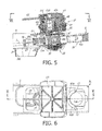
- the moving element or drawer 9 is again moved to the loading position of a new capsule, as shown in Figs. 5 and 6 .
- the elastic element 67 retains the spent capsule C, that is, just used in the infusion cycle that has just ended, in the infusion position, interposed between the hot water dispensing device 41 and the drink outlet nozzle 35.
- This spent capsule is discharged at the next infusion cycle, or with a loadless inwards movement of the moving element 9, as shown in Figs. 7 and 8 .
- arms 15B push the spent capsule C away from its infusion position bringing it towards the discharge opening 31.
- the inclination of the path (arrow f9) of the moving element 9 favours the discharge of the spent capsule and also the optional outflow towards the liquid discharge opening 31 that optionally remains in the infusion zone.
- the opening and closing movement of the elastic arms 15B for allowing the outlet of the spent capsule C and the subsequent ejection by thrust may be obtained by known systems, for example of the type described in WO-A-2009/069167 .
- the moving element 9 is brought to the position shown in Figs. 9 and 10 . With an extra-stroke outwards, the moving element 9 reaches such position that the washing member 19 is interposed between the drink outlet nozzle 35 and the hot water dispensing device 41, moving to the position normally taken by a capsule C.
- the hot water dispensing device 41 closes pushing piston 47 downwards until the bottom surface 53A of block 53 integral to piston 47 presses against the top face or surface 21A of body 21 of the washing member 19. The latter is pushed downwards with a bending of sheet 27 up to press the annular seal 23B against plate 69 surrounding the outlet port 37 of the beverage outlet nozzle 35. A sealed passage is thus formed that extends from the water dispensing opening 53B made on surface 53A up to port 37 and hence through the drink outlet nozzle 35, up to the drink dispensing spouts (not shown). By feeding hot water under pressure through conduit 57 it is so possible to wash the entire circuit downstream of surface 53A, removing any residues or deposits formed during the previous dispensing cycles.
- the movement of the moving element 9 can be obtained in any way. According to some embodiments, the movement is controlled manually for example by thrust, with a lever actuated by the user, or through an actuator, for example a hydraulic, pneumatic, electrical or similar actuator. In some embodiments it is possible to provide a pinion and rack mechanism, with a rack constrained to frame 11 of the moving element 9 and a pinion actuated by an electrical motor, not shown.
- the moving element 9 may be associated to microswitches for detecting its position during the various steps of the infusion or washing cycle, for providing the consensus to the dispensing of hot water under pressure.
- Fig. 11 schematically shows some components of the hydraulic circuit of machine 1.
- This figure shows a water tank 71 with an outlet conduit 73, whereon a feeding pump 75 is placed.
- Pump 75 feeds at an adequate pressure, for example between 8 and 12 bar, typically and preferably between 10 and 15 bar, the water collected from tank 71 towards the feeding conduit 77.
- the latter branches into a conduit 79 connected to conduit 48 described above for feeding the water under pressure provided by the pump 75 to the cylinder-piston actuator 43, 47.
- Reference numeral 81 indicates a second branching of conduit 77 that feeds a boiler 83.
- Boiler 83 may advantageously be an instant boiler, or a storage boiler.
- conduit 81 there is arranged a check valve 85 and a discharge valve 87 for discharging the pressure from the circuit at the end of the infusion cycle.
- a check valve 85 and a discharge valve 87 for discharging the pressure from the circuit at the end of the infusion cycle.
- the hot water under pressure is fed to a conduit 89 connected to conduit 57 described above, for feeding the hot water to chamber 55.
- a single pump 75 feeds water under pressure to both the closing actuator 43 and 47 of the infusion unit, and to the boiler that provides the water at the adequate pressure and temperature to the feeding chamber 55.
- the pressure in the circuit between pump 75 and the infusion unit 41 is discharged by opening valve 87.
- the check valve 85 prevents the outflow of water from boiler 83 towards the discharge and the calibrated valve 61 prevents the outflow of water towards the infusion zone.
- the arrangement of the calibrated valve 61 into the infusion unit prevents the need of a further check valve downstream of the boiler.
Description
- The present invention relates to improvements to machines for making beverages, in particular but not exclusively for making espresso coffee, and to the infusion units built in said machines.
- At present there exist different types of machines for making beverages, in particular for machines for making coffee such as espresso coffee or the like, of the automatic or semi-automatic type, for household or professional use, which use single-dose coffee capsules or other ingredients for making beverages, or loose products that are first inserted into a filter or cup that is then placed into an infusion unit.
-
WO-A-2009/069167 describes an infusion unit for making coffee, comprising a sliding drawer, forming a moving element with a seat for single-dose capsules containing coffee powder or other ingredients for making a beverage, in particular espresso coffee. The moving element can shift from a loading position of the capsules to an infusion position, wherein the capsule seat is interposed between a hot water dispensing device and a beverage outlet nozzle, opposite to each other. - In this type of infusion units it is necessary to wash the beverage dispensing circuit located downstream of the position in which the capsule containing the coffee powder is during the infusion, in order to remove the beverage residues that build up during use. To this end, an accessory is usually provided which consists of a sort of mock capsule that is manually inserted into the seat and used in replacement of a real capsule to carry out one or more washing cycles with hot water under pressure. By flowing through this washing capsule, the water crosses the beverage dispensing circuit removing any scrap or deposits. These accessories are inconvenient to use and are easily lost due to their small dimensions.
- Some coffee machines, in particular in machines using infusion capsules containing coffee powders, which are inserted in a drawer system of the type described above, exhibit a system for closing the infusion chamber of the hydraulic type. A piston moved under the thrust of water under pressure presses on top of the capsule closing the infusion chamber and feeding water under pressure and at a high temperature through the same capsule for extracting the aromas from the ingredients contained therein and producing the required beverage. An example of this infusion unit with hydraulic closure of the infusion chamber is described in
WO2009/093202 . In this known infusion unit, the piston also comprises a water heating system and is removably constrained to a stem stiffly connected to a hydraulic piston sliding in a hydraulic cylinder forming a cylinder/piston actuator with the above hydraulic piston. This system is particularly complex and expensive to manufacture. - The invention aims at totally or partly overcoming one or more of the drawbacks of the prior art.
- In one embodiment, the invention provides an infusion unit of the type described above, with a moving element or drawer fitted with a seat for single-dose capsules of doses of loose ingredients for making coffee or other beverage, a simpler and easier washing of the beverage dispensing circuit.
- To this end, according to some embodiments, the infusion unit provides for the moving element to integrally carry, that is, constrained thereto, a washing member which (through the movement of the moving element) may be positioned between the hot water dispensing device and the beverage outlet nozzle for forming a washing channel, wherethrough the water dispensed by the hot water dispensing device flows towards the beverage outlet nozzle. In this way it is possible to perform the washing cycle through a simple positioning of the moving element, without the need of inserting a special accessory within the single/dose capsule seat for performing the machine washing cycle.
- The washing operations of the infusion unit are greatly simplified and the risk of losing the washing accessories normally provided in traditional machines is prevented.
- Further and advantageous embodiments of the infusion unit according to the invention are indicated in the annexed claims, which form an integral part of the present description.
- Hereinafter, specific reference shall be made to an infusion unit made and configured for seating single-dose capsules of coffee powder. However, it should be understood that the concepts at the basis of the invention may advantageously be used also in machines for making other types of drinks, which use an extraction system through hot water which flows through a charge of suitably dosed ingredients.
- Moreover, hereinafter reference shall be made to systems for managing the capsules with a moving element that may take three different positions. However, in some embodiments, not shown, the moving element may be configured for taking two positions only, the extracted or charging position coinciding with the washing position.
- Moreover, in the following detailed description, reference shall be made to an exemplary embodiment wherein the infusion unit is made for handling single-dose capsules, for example made of a plastic material or the like, which contain coffee powder or other ingredients for making the beverage. However, it should be understood that the concepts at the basis of the invention may advantageously be used also in machines and infusion units wherein the ingredients are inserted into the machine in a different manner, for example placing them into a cup or filter, that is, in a containment member provided with a pierced wall that allows the outflow of the beverage or other food product obtained by extracting the flavours from the ingredients with hot water under pressure.
- The invention also relates to a coffee machine comprising an infusion unit of the type defined above.
- The invention will be better understood by following the description and accompanying drawing, which shows a non-limiting practical embodiment of the invention. More in particular, in the drawing:
-
Fig. 1 shows a vertical a section according to the trace plane I-I ofFig. 2 , of an infusion unit according to the invention in a position of charging a single-dose capsule; -
Fig. 2 shows a plan view according to II-II ofFig. 1 ; -
Figs. 3 and 4 respectively show a section according to a vertical plane of trace III-III inFig. 4 and a plan view according to IV-IV ofFig. 3 of the infusion unit in the infusion position before closing the infusion chamber; -
Figs. 5 and 6 show a section according to V-V inFig. 6 and a plan view according to VI-VI ofFig. 5 of the same infusion unit in the step subsequent to an infusion cycle; -
Figs. 7 and 8 show a section according to VII-VII and a plan view according to VIII-VIII of the infusion unit in the step of ejection of an spent single-dose capsule; -
Figs. 9 and 10 show a cutaway view according to a vertical plane IX-IX ofFig. 10 and according to a plan view according to X-X ofFig. 9 of the infusion unit in a washing step; -
Fig. 11 schematically shows some components of the hydraulic circuit associated to the infusion unit; -
Fig. 12 schematically shows a coffee machine incorporating the infusion unit ofFigs. 1 to 10 ; and -
Fig. 13 shows a section according to a trace plan XIII-XIII ofFig. 1 of the dispensing device of the water under pressure in the infusion chamber. -
Fig. 12 globally indicates a coffee machine 1, wherein an infusion unit according to the invention is built in, as shall be better described hereinafter inFigs. 1 to 10 . Machine 1 comprises, in a per se known manner, a water tank, a pump for feeding the water to a boiler, wherefrom the hot water under pressure is fed to the infusion unit, described hereinafter. In a per se known manner, the water fed by the pump is also used for closing the infusion unit, as shall be better described hereinafter. - The infusion unit and its operation are illustrated in detail in the sequence of
Figs. 1 to 10 . - The infusion unit, globally indicated with 3, comprises a
bearing structure 5 defining side guides 7 for the sliding (according to the double arrow f9) of a moving element or unit globally indicated with 9. The moving element 9 is substantially configured as a drawer sliding along guides 7 and substantially exhibits a frame with a substantiallyrectangular development 11 with a wide window orcentral opening 13 that extends longitudinally in the direction of arrow f9. The trajectory performed by the moving element 9 is inclined relative to the horizontal for the purposes that shall be explained hereinafter. - The moving element 9 carries a
seat 15 for receiving single-dose capsules C of coffee powder for making espresso coffee or similar beverages. According to some embodiments,seat 15 is delimited on the one side by awall 15A, with circa semi-cylindrical development, and on the opposite side by a pair of oscillatingarms 15B hinged in 17 to the moving element 9. The inside surfaces of the oscillatingarms 15B and the inside surface ofwall 15A laterally delimit an infusion chamber whose shape corresponds to the shape of the single-dose capsule C. The infusion chamber is completed and closed at the top and at the bottom by mechanical components described hereinafter, so as to define a closed volume wherethrough hot water under pressure is made to flow to extract the flavours contained in the single-dose capsule C. - The moving element 9 is fixed to a washing member globally indicated with 19. In some embodiments, the
washing member 19 exhibits a substantiallycylindrical body 21 having atop face 21A and a bottom face 21B. In some embodiments, an annular seat is made on thetop face 21A for aseal 23A, whereas an annular seat is made on the bottom face for a bottom seal 23B, for the purposes described hereinafter. Aconduit 25 develops through the substantiallycylindrical body 21 of thewashing member 19 that crosses theentire body 21 and is open on thetop face 21A and on the bottom face 21B and more exactly at respective lowered zones made on said two top 21A and bottom 21B faces. -
Body 21 of thewashing member 19 is steadily constrained to the moving member 9 to move therewith. In some embodiments, the constraint betweenbody 21 of thewashing member 19 and the moving member 9 comprises an elastic element, for example anelastic sheet 27. In some embodiments, thiselastic sheet 27 is formed integrally, withbody 21 and with the moving element 9 or more exactly withframe 11 that is the main part thereof. This allows making the device with a simple plastic moulding operation. Theelastic sheet 27 acts as laminar spring and allows a movement ofbody 21 of thewashing member 19 in a direction substantially orthogonal to direction f9 of movement of the moving member 9 for the purposes described hereinafter. - In some embodiments,
structure 5 exhibits a discharge opening 31 with a discharge hopper 33 developing downwards to discharge the spent capsules C. A collecting container, not shown, may be positioned underneath the discharge opening 31. Adjacent the discharge opening 31structure 5 carries an outlet nozzle of the beverage, globally indicated with 35. The nozzle may be fitted with two side spouts that allow dispensing the coffee or other beverage in one or two cups located one adjacent the other on aplane 1A (Fig. 12 ) machine 1 is provided with. - In some embodiments,
nozzle 35 for the beverage outlet is fitted with an outlet opening 37, preferably closed by acounter pressure valve 39 comprising for example a gate and an elastic member, in the example shown formed by a compression spring. Thecounter pressure valve 39 opens when the pressure of the infusion water in capsule C has reached a certain value, the valve being calibrated for obtaining particular organoleptic features of the drink. -
Structure 5 carries, in a position overlying and opposite theoutlet nozzle 35 of the beverage, a hotwater dispensing device 41. In some embodiments, the dispensingdevice 41 exhibits a hydraulic closing system of the infusion chamber, as shown in the drawing. It should be understood that in other embodiments, the hot water dispensing device may be made in a different way and have for example a mechanical closing system. In the embodiment shown, the hot water dispensing device has no piercer, as it uses capsules C that need not be pierced. However, it should be understood that in other embodiments, the hotwater dispensing device 41 may be provided with a top piercer to pierce capsules C at the top. In the example shown there is provided a bottom piercer to pierce the bottom surface in capsules C. - In the example shown, the hot
water dispensing device 41 comprises a cylinder-piston actuator the cylinder whereof consists at least partly of aliner 43 seated in aseat 45 and locked therein by a closingflange 46.Liner 43 has atop closing wall 43A wherein a port 43B for feeding water under pressure opens. Port 43B is in connection with a chamber 43C wherein afirst conduit 48 leads that feeds water under pressure fed by a pump, as shall be described hereinafter with reference to the schematic representation of the hydraulic circuitFig. 11 . - Inside the cylinder formed by
liner 43, apiston 47 slides fitted with anannular seal 49 and at the top forming apressure surface 47A.Piston 47 also forms a collar 47B, surrounding amain body 47C ofpiston 47. Aboutbody 47C and underneath collar 47B there are arranged elastic members acting on the piston with a force opposite the force exerted by the water under pressure fed throughconduit 48. In the embodiment shown, the elastic members are formed by compression springs 51 arranged about the axis ofpiston 47 in a suitable number, for example three or four.Springs 51 are compressed between collar 47B ofpiston 47 andflange 46 constrained toseat 45. - In some embodiments,
body 47C ofpiston 47 is integral to ablock 53 forming achamber 55 for feeding hot water under pressure.Chamber 55 is in connection with aconduit 57 for feeding hot water under pressure coming from the boiler machine 1 is fitted with and that shall be described briefly with reference toFig. 11 . From the feedingchamber 55, the hot water reaches a dispensing opening 53B (Fig. 13 ) made on abottom surface 53A ofblock 53, which forms a closing surface of the infusion chamber. - In some embodiments,
chamber 55 for feeding the hot water and the dispensing opening 53B made onsurface 53A ofblock 53 are in flow communication through aport 55A (Fig. 13 ) that is closed by a calibratedvalve 61. The latter comprises agate 63 elastically stressed by an elastic member, for example a helical compression spring 65 seated, along withgate 63, within a sliding seat formed inbody 47C ofpiston 47. This calibratedvalve 63 allows the proper operation of the hotwater dispensing device 41 as shall be better clarified hereinafter with reference to the dispensing cycle. Achannel 56 extends between opening 53B andport 55A visible in the section ofFig. 13 , wherethrough the hot water under pressure flows when it has reached an opening pressure of the calibratedvalve 61. - In some embodiments, the block formed by
flange 46 and byseat 45 is fixed relative to structure 5 and anelastic element 67 is constrained thereto, for example formed by a shaped elastic sheet having the function of ejecting capsule C fromseat 15. - The infusion unit 3 described hereinbefore operates as follows.
Fig. 1 shows the position that the infusion unit takes when a new capsule C is charged intoseat 15. The moving element or sliding drawer 9 is in a charging position, so as to be accessible to the user from outside machine 1. In this way it is easy to insert capsule C into the seat formed between theoscillating arms 15B and the fixedwall 15A constrained to the moving element 9. - In the next step, shown in
Figs. 3 and 4 , the moving element or drawer 9 is pushed within the machine up to movingseat 15 in alignment with the hotwater dispensing device 41 and with thebeverage outlet nozzle 35. In this position, capsule C is arranged with its bottom in contact with adisc 69 defining the bottom wall of the infusion chamber, the side walls thereof are formed byarms 15B and bywall 15A. As is seen by comparingFigs. 1 and3 , capsule C has been brought to its infusion position (Fig. 3 ) going beyond theelastic element 67 which in rest condition, is at a lower height than the top flange CF of capsule C in infusion position. This is made possible by the elasticity of theelastic element 67 and by the chamfered shape thereof that allows, under the effect of the thrust given by the moving element 9, the lifting of theelastic movement 67 and the overtaking of the latter by capsule C. - In the position of
Fig. 3 the hotwater dispensing device 41 is actuated feeding water under pressure in the cylinder formed byliner 43. The compression pusheswall 47A ofpiston 47 downwards causing the compression ofsprings 51 and thus the lowering ofsurface 53A against the top surface of capsule C in this way defining the top closing wall of the infusion chamber. The latter therefore remains formed by the bottom closing wall orsurface 53A constrained topiston 47, byarms 15B, bywall 15A and by the wall formed bydisc 69 associated to thedrink outlet nozzle 35. - The hot water under pressure fed through
conduit 57 acts on the calibratedvalve 61 to cause the opening thereof through the compression of spring 65 and upwards sliding of the cursor orgate 63, so as to put the hot water dispensing opening 53B in communication with the hotwater feeding chamber 55.Valve 61 is calibrated so that the opening pressure is sufficiently high to ensure an adequate pressure in capsule C, but sufficiently limited to ensure an adequate seal between the closingsurface 53A and the top face or surface of capsule C. In some embodiments, the hot water under pressure fed tochamber 55 and the water under pressure fed to the cylinder-piston actuator valve 61 considering the pressure at which the flavour extraction from the ingredients contained in capsule C must be carried out, the value of the closing force to be exerted on capsule C by the cylinder-piston actuator and the area ofsurfaces - In
Fig. 3 , the infusion unit is shown in the position immediately before the activation of the dispensingdevice 41, with theclosing surface 53A of the infusion chamber still at a certain distance relative to the top surface of capsule C. It should be understood that the infusion occurs whenpiston 47 has lowered up to bringingsurface 53A to press against the top surface of capsule C. - At the end of the drink dispensing,
piston 47 is returned to the rest position by the effect ofsprings 51 and discharging the pressure into the circuit that feedsconduit 48 andconduit 57, so that alsovalve 61 closes. - Once pressure has been discharged, the moving element or drawer 9 is again moved to the loading position of a new capsule, as shown in
Figs. 5 and 6 . During this return movement of the moving element 9, theelastic element 67 retains the spent capsule C, that is, just used in the infusion cycle that has just ended, in the infusion position, interposed between the hotwater dispensing device 41 and thedrink outlet nozzle 35. This spent capsule is discharged at the next infusion cycle, or with a loadless inwards movement of the moving element 9, as shown inFigs. 7 and 8 . In this movement,arms 15B push the spent capsule C away from its infusion position bringing it towards thedischarge opening 31. The inclination of the path (arrow f9) of the moving element 9 favours the discharge of the spent capsule and also the optional outflow towards the liquid discharge opening 31 that optionally remains in the infusion zone. The opening and closing movement of theelastic arms 15B for allowing the outlet of the spent capsule C and the subsequent ejection by thrust may be obtained by known systems, for example of the type described inWO-A-2009/069167 . - To carry out a washing cycle, the moving element 9 is brought to the position shown in
Figs. 9 and 10 . With an extra-stroke outwards, the moving element 9 reaches such position that thewashing member 19 is interposed between thedrink outlet nozzle 35 and the hotwater dispensing device 41, moving to the position normally taken by a capsule C. - Once this position has been reached, the hot
water dispensing device 41closes pushing piston 47 downwards until thebottom surface 53A ofblock 53 integral topiston 47 presses against the top face orsurface 21A ofbody 21 of thewashing member 19. The latter is pushed downwards with a bending ofsheet 27 up to press the annular seal 23B againstplate 69 surrounding theoutlet port 37 of thebeverage outlet nozzle 35. A sealed passage is thus formed that extends from the water dispensing opening 53B made onsurface 53A up toport 37 and hence through thedrink outlet nozzle 35, up to the drink dispensing spouts (not shown). By feeding hot water under pressure throughconduit 57 it is so possible to wash the entire circuit downstream ofsurface 53A, removing any residues or deposits formed during the previous dispensing cycles. - The movement of the moving element 9 can be obtained in any way. According to some embodiments, the movement is controlled manually for example by thrust, with a lever actuated by the user, or through an actuator, for example a hydraulic, pneumatic, electrical or similar actuator. In some embodiments it is possible to provide a pinion and rack mechanism, with a rack constrained to frame 11 of the moving element 9 and a pinion actuated by an electrical motor, not shown. The moving element 9 may be associated to microswitches for detecting its position during the various steps of the infusion or washing cycle, for providing the consensus to the dispensing of hot water under pressure.
-
Fig. 11 schematically shows some components of the hydraulic circuit of machine 1. This figure shows awater tank 71 with anoutlet conduit 73, whereon afeeding pump 75 is placed.Pump 75 feeds at an adequate pressure, for example between 8 and 12 bar, typically and preferably between 10 and 15 bar, the water collected fromtank 71 towards the feedingconduit 77. The latter branches into aconduit 79 connected toconduit 48 described above for feeding the water under pressure provided by thepump 75 to the cylinder-piston actuator Reference numeral 81 indicates a second branching ofconduit 77 that feeds aboiler 83.Boiler 83 may advantageously be an instant boiler, or a storage boiler. Alongconduit 81 there is arranged acheck valve 85 and a discharge valve 87 for discharging the pressure from the circuit at the end of the infusion cycle. Fromboiler 83, the hot water under pressure is fed to aconduit 89 connected toconduit 57 described above, for feeding the hot water tochamber 55. - From this brief description of the hydraulic circuit it is understood that a
single pump 75 feeds water under pressure to both the closingactuator chamber 55. At the end of the infusion cycle, the pressure in the circuit betweenpump 75 and theinfusion unit 41 is discharged by opening valve 87. Thecheck valve 85 prevents the outflow of water fromboiler 83 towards the discharge and the calibratedvalve 61 prevents the outflow of water towards the infusion zone. The arrangement of the calibratedvalve 61 into the infusion unit prevents the need of a further check valve downstream of the boiler. - It is understood that the drawing shows just one example, provided merely as a practical demonstration of the invention, which can vary in its forms and arrangements, without however departing from the scope of the concept underlying the invention. Any reference numbers in the appended claims are provided to facilitate reading of the claims with reference to the description and to the drawing, and do not limit the scope of protection represented by the claims.
Claims (15)
- An infusion unit (3) for making drinks, comprising a moving element (9) with a seat (15) for the ingredients for making said drinks, movable from an ingredient charging position to an infusion position, wherein said seat is between a hot water dispensing device (41) and a beverage outlet nozzle (35) opposite to one another, characterised in that said moving element is integral to a washing member (19) that by moving said moving element may be positioned between said hot water dispensing device and said beverage outlet nozzle for forming a washing channel, wherethrough the water dispensed by said hot water dispensing device flows towards said beverage outlet nozzle.
- Infusion unit (3) according to claim 1, characterised in that said seat (15) is configured for seating single-dose capsules (C) containing the ingredients for making beverages.
- Infusion unit (3) according to claim 1 or 2, characterised in that said moving element (9) is provided with a sliding movement according to a trajectory passing by the hot water dispensing device (41) and the beverage outlet nozzle (35) to take three alternative positions: said ingredient charging position, said infusion position and a washing position, the infusion position being intermediate between the charging position and the washing position.
- Infusion unit (3) according to claim 1, 2 or 3, characterised in that said moving element (9) comprises a frame structure with an opening extending according to a longitudinal direction parallel to the direction of the movement of said moving element, said seat (15) and said washing member (19) being arranged in said opening.
- Dispensing unit (3) according to one or more of the previous claims, characterised in that said washing member (19) comprises a body (21) with a top face (2 1 a) and a bottom face (21b), wherethrough an open conduit extends on said top face and on said bottom face, the top face forming a surface cooperating with said hot water dispensing device (41) and said bottom face forming a surface cooperating with said beverage outlet nozzle (35).
- Infusion unit (3) according to claim 5, characterised in that said washing member (19) comprises seals (23a, 23b) on said top face (21a) and on said bottom face (21b).
- Infusion unit (3) according to one or more of the previous claims, characterised in that said washing member (19) is constrained to said moving element (9) by an elastic connection that allows the movement of the washing member towards the beverage outlet nozzle (35) under the thrust of the hot water dispensing device (41).
- Infusion unit (3) according to one or more of the previous claims, characterised in that said dispensing device (41) comprises a cylinder-piston actuator fed by a circuit of water under pressure that controls a closing movement of the dispensing device towards said seat (15), and in that the piston (47) of said actuator is associated to a feeding conduit (57) of hot water under pressure, the piston having a chamber (55) for feeding the hot water under pressure with an outlet port of the hot water on a closing surface (53A) cooperating with said seat.
- Infusion unit (3) according to claim 8, characterised in that said closing surface (53A) is made and arranged for sealing on a surface of a single-dose capsule (C) containing the ingredients for making said beverages seated in said seat (15).
- Infusion unit (3) according to one or more of the previous claims, characterised in that it comprises a discharge opening (31) for spent capsules (C) containing the ingredients for making said beverages.
- Infusion unit (3) according to claim 10, characterised in that it comprises a stopping element of single-dose capsules containing the ingredients for making said beverages, for retaining a capsule (C) in an infusion position between the hot water dispensing device (41) and the beverage outlet nozzle (35) when the moving element (19) is returned to the charging position, said moving element comprising an ejector for ejecting the capsule from the infusion position when the subsequent movement is carried out from the charging position to the infusion position, so as to push the capsule held into infusion position towards said discharge opening (31).
- Infusion unit (3) according to one or more of the previous claims, characterised in that said seat (15) is configured for receiving a capsule of ingredients for making said beverages and for releasing a capsule in the infusion position when said moving element (19) is moved from the infusion position to the charging position.
- Infusion unit (3) according to one or more of the previous claims, characterised in that said beverage outlet nozzle (35) comprises a counter pressure valve (39) that opens when the pressure of the beverage being prepared has reached a predetermined value.
- Infusion unit (3) according to one or more of the previous claims, characterised in that said seat (15) comprises a pair of oscillating arms (15b) defining a seat for single-dose capsules containing the ingredients for making said beverages.
- Coffee machine (1) comprising an infusion unit (3) according to one or more of claims 1 - 14.
Applications Claiming Priority (2)
| Application Number | Priority Date | Filing Date | Title |
|---|---|---|---|
| ITFI2009A000267A IT1397492B1 (en) | 2009-12-21 | 2009-12-21 | INFUSION GROUP FOR BEVERAGES WITH A WASHING SYSTEM. |
| PCT/IB2010/055941 WO2011077349A2 (en) | 2009-12-21 | 2010-12-20 | Infusion unit for drinks with washing system |
Publications (2)
| Publication Number | Publication Date |
|---|---|
| EP2515727A2 EP2515727A2 (en) | 2012-10-31 |
| EP2515727B1 true EP2515727B1 (en) | 2013-10-16 |
Family
ID=42710604
Family Applications (1)
| Application Number | Title | Priority Date | Filing Date |
|---|---|---|---|
| EP10812927.1A Active EP2515727B1 (en) | 2009-12-21 | 2010-12-20 | Infusion unit for drinks with washing system |
Country Status (10)
| Country | Link |
|---|---|
| US (1) | US8881643B2 (en) |
| EP (1) | EP2515727B1 (en) |
| JP (1) | JP5694370B2 (en) |
| KR (1) | KR20120106833A (en) |
| CN (1) | CN102665504B (en) |
| BR (1) | BR112012015027B1 (en) |
| IT (1) | IT1397492B1 (en) |
| MX (1) | MX2012007157A (en) |
| RU (1) | RU2542565C2 (en) |
| WO (1) | WO2011077349A2 (en) |
Cited By (1)
| Publication number | Priority date | Publication date | Assignee | Title |
|---|---|---|---|---|
| US9282849B2 (en) | 2014-03-11 | 2016-03-15 | Starbucks Corporation | Beverage production machines with restrictors |
Families Citing this family (18)
| Publication number | Priority date | Publication date | Assignee | Title |
|---|---|---|---|---|
| EP2543291A1 (en) * | 2011-07-08 | 2013-01-09 | Koninklijke Philips Electronics N.V. | Brewing unit with a water heater |
| WO2013014047A1 (en) * | 2011-07-22 | 2013-01-31 | Ciaramelli Marco | Beverage production method and devices |
| WO2013188246A2 (en) * | 2012-06-10 | 2013-12-19 | Urnex Inc. | System and method for cleaning a brewing machine |
| AU2014250125A1 (en) * | 2013-04-03 | 2015-11-05 | Koninklijke Douwe Egberts B.V. | Pad with a relatively large outlet opening comprising a soluble beverage preparation product for use in a coffee machine |
| EP2981198A4 (en) | 2013-04-03 | 2016-11-16 | 2266170 Ontario Inc | Capsule machine and components |
| WO2014163498A2 (en) | 2013-04-03 | 2014-10-09 | Koninklijke Douwe Egberts B.V. | Coffee pad for use in a coffee machine |
| RU2015147000A (en) | 2013-04-03 | 2017-05-10 | Конинклейке Дауве Егбертс Б.В. | PALS CONTAINING A SOLUBLE PRODUCT FOR PREPARING A DRINK, FOR USE IN A COFFEE MACHINE |
| US9375114B2 (en) | 2013-05-22 | 2016-06-28 | Sunbeam Products, Inc. | Hot beverage maker with cleaning apparatus and related method |
| US20150129003A1 (en) * | 2013-11-13 | 2015-05-14 | Uni-Splendor Corp. | Coffee Brewer Nozzle Cleaning Device |
| DE102014109760B4 (en) * | 2014-07-11 | 2018-06-28 | Melitta Single Portions Gmbh & Co. Kg | Apparatus and method for preparing a brewed beverage |
| DE102014109761B4 (en) | 2014-07-11 | 2020-07-09 | Melitta Single Portions Gmbh & Co. Kg | Device and method for preparing a brewed beverage |
| ES2720260T3 (en) | 2014-09-29 | 2019-07-19 | Koninklijke Philips Nv | Consumable for a dispenser and processing unit for a dispenser |
| US10610044B2 (en) | 2014-12-19 | 2020-04-07 | Koninklijke Philips N.V. | Processing unit, system comrising a consumable and use of a consumable |
| US10694886B2 (en) | 2014-12-19 | 2020-06-30 | Koninklijke Philips N.V. | Capsule-type consumable for use in a dispenser for the preparation of foodstuff products and processing unit for such a dispenser |
| RU2695831C1 (en) * | 2015-07-03 | 2019-07-29 | САГА Коффее С.п.А. | Beverage preparation machine |
| PT109303B (en) * | 2016-04-07 | 2021-02-15 | Novadelta Comercio Ind Cafes Sa | EXTRACTION DEVICE WITH MOBILE CAPSULE SUPPORT |
| PL3831254T3 (en) * | 2018-08-01 | 2023-10-09 | Novadelta - Comércio e Indústria de Cafés, Unipessoal Lda | Beverage distribution system with enhanced purge and residues discharge, and process of operation of said system |
| CN114286804A (en) * | 2019-08-30 | 2022-04-05 | 77视觉路有限公司 | Device for dispensing mineralized water and associated method |
Family Cites Families (20)
| Publication number | Priority date | Publication date | Assignee | Title |
|---|---|---|---|---|
| IT1194662B (en) * | 1980-06-11 | 1988-09-22 | Giuseppe Stefano Piana | MACHINE FOR THE PREPARATION OF ESPRESSO COFFEE, CAPPUCCINO, TEA, BROTH OR OTHER INFUSIONS, AUTOMATICALLY OPERATED, BY A DISPOSABLE FILTER, CONTAINING ONE OR MORE DOSES OF PRODUCTS, INTRODUCED AS A COIN |
| IT8423846V0 (en) * | 1984-11-21 | 1984-11-21 | Cavalli Alfredo | DOMESTIC USE EQUIPMENT FOR THE AUTOMATIC PREPARATION OF ESPRESSO COFFEE. |
| US4709625A (en) * | 1986-10-22 | 1987-12-01 | Gross-Given Manufacturing Co. | Dispensing machine for tea |
| DK162918C (en) * | 1989-09-21 | 1992-05-25 | Wittenborg As | APPLICATION FOR PORTFOLIOUS USE OF BEVERAGES, ESPECIALLY COFFEE |
| DE59007858D1 (en) * | 1990-02-20 | 1995-01-12 | Wmf Wuerttemberg Metallwaren | Coffee machine. |
| IT1310537B1 (en) * | 1999-02-22 | 2002-02-18 | Simac Vetrella Spa | MACHINE FOR THE PRODUCTION OF ESPRESSO COFFEE |
| CN2527198Y (en) * | 2001-08-20 | 2002-12-25 | 美国·灿坤公司 | Coffee-making apparatus for electric coffee maker |
| US6955116B2 (en) * | 2003-06-13 | 2005-10-18 | Robert Hale | Beverage dispensing machine including cartridge ejector assembly |
| PL1656863T3 (en) * | 2004-11-11 | 2011-07-29 | Nestec Sa | Self-cleaning mixing head for producing a milk-based mixture and beverage production machines comprising such a mixing head |
| CN2746853Y (en) * | 2004-11-23 | 2005-12-21 | 大统营实业股份有限公司 | Coffee processing apparatus |
| PL1688072T3 (en) * | 2005-02-07 | 2008-09-30 | Nestec Sa | Device for preparing a beverage from a capsule by injecting a pressurized fluid |
| EP1829954B1 (en) * | 2006-03-03 | 2014-05-07 | Diversey, Inc. | Unit dose detergent for cleaning a coffee machine |
| DK1967100T3 (en) * | 2007-03-06 | 2009-07-20 | Nestec Sa | System and method for preparing a nutrient liquid from a capsule |
| ITBA20070054A1 (en) * | 2007-07-13 | 2009-01-14 | Spinel Srl | IMPROVEMENT OF ESPRESSO COFFEE MAKING MACHINES BY USING GROUND COFFEE COFFEE PODS |
| CN201061463Y (en) * | 2007-07-23 | 2008-05-21 | 王冬雷 | Device for preparing hot beverage |
| ITFI20070267A1 (en) | 2007-11-28 | 2009-05-29 | Saeco Ipr Ltd | "INFUSION GROUP FOR THE PREPARATION OF DRINKS FROM SINGLE-DOSE PACKAGES AND MACHINE INCLUDING THE GROUP" |
| WO2009093202A2 (en) * | 2008-01-23 | 2009-07-30 | Moka Efti S.P.A. | Machine for infusion drinks with raw material in single-dose packaging |
| US8807019B2 (en) * | 2008-02-05 | 2014-08-19 | Luigi Lavazza S.P.A. | Granular infusion cartridge loading and ejecting device and related beverage dispensing machine |
| IT1394284B1 (en) * | 2009-05-21 | 2012-06-06 | Saeco Strategic Services Ltd | INFUSION GROUP FOR THE PREPARATION OF BEVERAGES FROM SINGLE-DOSE PACKAGES AND MACHINE INCLUDING THE GROUP |
| DE102010027523A1 (en) * | 2010-07-16 | 2012-01-19 | Krüger Gmbh & Co. Kg | Cleaning capsule for coffee dispenser, comprises disposing unit, such that cleaning capsule is prevented from inserting in brewing chamber, where disposing unit is provided as removed boundary |
-
2009
- 2009-12-21 IT ITFI2009A000267A patent/IT1397492B1/en active
-
2010
- 2010-12-20 BR BR112012015027-8A patent/BR112012015027B1/en not_active IP Right Cessation
- 2010-12-20 KR KR1020127018987A patent/KR20120106833A/en not_active Application Discontinuation
- 2010-12-20 RU RU2012131329/12A patent/RU2542565C2/en active
- 2010-12-20 CN CN201080058430.9A patent/CN102665504B/en active Active
- 2010-12-20 MX MX2012007157A patent/MX2012007157A/en active IP Right Grant
- 2010-12-20 JP JP2012543990A patent/JP5694370B2/en not_active Expired - Fee Related
- 2010-12-20 US US13/517,107 patent/US8881643B2/en active Active
- 2010-12-20 EP EP10812927.1A patent/EP2515727B1/en active Active
- 2010-12-20 WO PCT/IB2010/055941 patent/WO2011077349A2/en active Application Filing
Cited By (1)
| Publication number | Priority date | Publication date | Assignee | Title |
|---|---|---|---|---|
| US9282849B2 (en) | 2014-03-11 | 2016-03-15 | Starbucks Corporation | Beverage production machines with restrictors |
Also Published As
| Publication number | Publication date |
|---|---|
| EP2515727A2 (en) | 2012-10-31 |
| JP2013514825A (en) | 2013-05-02 |
| RU2542565C2 (en) | 2015-02-20 |
| CN102665504A (en) | 2012-09-12 |
| BR112012015027A8 (en) | 2018-02-06 |
| BR112012015027A2 (en) | 2017-12-12 |
| RU2012131329A (en) | 2014-01-27 |
| MX2012007157A (en) | 2012-07-03 |
| WO2011077349A2 (en) | 2011-06-30 |
| US8881643B2 (en) | 2014-11-11 |
| CN102665504B (en) | 2015-08-19 |
| KR20120106833A (en) | 2012-09-26 |
| ITFI20090267A1 (en) | 2011-06-22 |
| JP5694370B2 (en) | 2015-04-01 |
| US20130112082A1 (en) | 2013-05-09 |
| WO2011077349A3 (en) | 2011-11-17 |
| BR112012015027B1 (en) | 2020-01-07 |
| IT1397492B1 (en) | 2013-01-16 |
Similar Documents
| Publication | Publication Date | Title |
|---|---|---|
| EP2515727B1 (en) | Infusion unit for drinks with washing system | |
| EP2515726B1 (en) | Infusion unit for drinks with hydraulic closing system | |
| AU2002344146B2 (en) | Extracting device with integrated capsule loading system | |
| US10405690B2 (en) | Single serve brewing machine | |
| KR102314294B1 (en) | Apparatus and method for preparing a brewed beverage | |
| JP4030502B2 (en) | Apparatus and method for selecting and extracting capsules for preparing beverages | |
| RU2525068C2 (en) | Device for extraction of cartridge | |
| AU2012298465B2 (en) | Cartridge positioning system | |
| EP2747611A1 (en) | Cartridge chamber of extraction system | |
| EP2747608A1 (en) | Long-lasting cartridge piercer | |
| CN111315267B (en) | Machine for multi-ingredient beverage preparation from various container types and system thereof | |
| CN109561780A (en) | It is used to prepare system, device, method, capsule and the capsule kit of beverage | |
| EP3206543B1 (en) | Infusion group for machines for the dispensing of beverages in the form of infusion | |
| EP4081081B1 (en) | Coffee machine, closing and/or tamping system and valve arrangement suitable for use in a coffee machine |
Legal Events
| Date | Code | Title | Description |
|---|---|---|---|
| PUAI | Public reference made under article 153(3) epc to a published international application that has entered the european phase |
Free format text: ORIGINAL CODE: 0009012 |
|
| 17P | Request for examination filed |
Effective date: 20120723 |
|
| AK | Designated contracting states |
Kind code of ref document: A2 Designated state(s): AL AT BE BG CH CY CZ DE DK EE ES FI FR GB GR HR HU IE IS IT LI LT LU LV MC MK MT NL NO PL PT RO RS SE SI SK SM TR |
|
| DAX | Request for extension of the european patent (deleted) | ||
| GRAP | Despatch of communication of intention to grant a patent |
Free format text: ORIGINAL CODE: EPIDOSNIGR1 |
|
| INTG | Intention to grant announced |
Effective date: 20130508 |
|
| GRAS | Grant fee paid |
Free format text: ORIGINAL CODE: EPIDOSNIGR3 |
|
| GRAA | (expected) grant |
Free format text: ORIGINAL CODE: 0009210 |
|
| RAP1 | Party data changed (applicant data changed or rights of an application transferred) |
Owner name: KONINKLIJKE PHILIPS N.V. |
|
| AK | Designated contracting states |
Kind code of ref document: B1 Designated state(s): AL AT BE BG CH CY CZ DE DK EE ES FI FR GB GR HR HU IE IS IT LI LT LU LV MC MK MT NL NO PL PT RO RS SE SI SK SM TR |
|
| REG | Reference to a national code |
Ref country code: GB Ref legal event code: FG4D |
|
| REG | Reference to a national code |
Ref country code: CH Ref legal event code: EP |
|
| REG | Reference to a national code |
Ref country code: IE Ref legal event code: FG4D |
|
| REG | Reference to a national code |
Ref country code: AT Ref legal event code: REF Ref document number: 636040 Country of ref document: AT Kind code of ref document: T Effective date: 20131115 |
|
| REG | Reference to a national code |
Ref country code: DE Ref legal event code: R096 Ref document number: 602010011078 Country of ref document: DE Effective date: 20131212 |
|
| REG | Reference to a national code |
Ref country code: NL Ref legal event code: VDEP Effective date: 20131016 |
|
| REG | Reference to a national code |
Ref country code: AT Ref legal event code: MK05 Ref document number: 636040 Country of ref document: AT Kind code of ref document: T Effective date: 20131016 |
|
| REG | Reference to a national code |
Ref country code: LT Ref legal event code: MG4D |
|
| PG25 | Lapsed in a contracting state [announced via postgrant information from national office to epo] |
Ref country code: SE Free format text: LAPSE BECAUSE OF FAILURE TO SUBMIT A TRANSLATION OF THE DESCRIPTION OR TO PAY THE FEE WITHIN THE PRESCRIBED TIME-LIMIT Effective date: 20131016 Ref country code: FI Free format text: LAPSE BECAUSE OF FAILURE TO SUBMIT A TRANSLATION OF THE DESCRIPTION OR TO PAY THE FEE WITHIN THE PRESCRIBED TIME-LIMIT Effective date: 20131016 Ref country code: HR Free format text: LAPSE BECAUSE OF FAILURE TO SUBMIT A TRANSLATION OF THE DESCRIPTION OR TO PAY THE FEE WITHIN THE PRESCRIBED TIME-LIMIT Effective date: 20131016 Ref country code: LT Free format text: LAPSE BECAUSE OF FAILURE TO SUBMIT A TRANSLATION OF THE DESCRIPTION OR TO PAY THE FEE WITHIN THE PRESCRIBED TIME-LIMIT Effective date: 20131016 Ref country code: NO Free format text: LAPSE BECAUSE OF FAILURE TO SUBMIT A TRANSLATION OF THE DESCRIPTION OR TO PAY THE FEE WITHIN THE PRESCRIBED TIME-LIMIT Effective date: 20140116 Ref country code: IS Free format text: LAPSE BECAUSE OF FAILURE TO SUBMIT A TRANSLATION OF THE DESCRIPTION OR TO PAY THE FEE WITHIN THE PRESCRIBED TIME-LIMIT Effective date: 20140216 Ref country code: NL Free format text: LAPSE BECAUSE OF FAILURE TO SUBMIT A TRANSLATION OF THE DESCRIPTION OR TO PAY THE FEE WITHIN THE PRESCRIBED TIME-LIMIT Effective date: 20131016 Ref country code: BE Free format text: LAPSE BECAUSE OF FAILURE TO SUBMIT A TRANSLATION OF THE DESCRIPTION OR TO PAY THE FEE WITHIN THE PRESCRIBED TIME-LIMIT Effective date: 20131016 |
|
| PG25 | Lapsed in a contracting state [announced via postgrant information from national office to epo] |
Ref country code: CY Free format text: LAPSE BECAUSE OF FAILURE TO SUBMIT A TRANSLATION OF THE DESCRIPTION OR TO PAY THE FEE WITHIN THE PRESCRIBED TIME-LIMIT Effective date: 20131016 Ref country code: RS Free format text: LAPSE BECAUSE OF FAILURE TO SUBMIT A TRANSLATION OF THE DESCRIPTION OR TO PAY THE FEE WITHIN THE PRESCRIBED TIME-LIMIT Effective date: 20131016 Ref country code: AT Free format text: LAPSE BECAUSE OF FAILURE TO SUBMIT A TRANSLATION OF THE DESCRIPTION OR TO PAY THE FEE WITHIN THE PRESCRIBED TIME-LIMIT Effective date: 20131016 Ref country code: ES Free format text: LAPSE BECAUSE OF FAILURE TO SUBMIT A TRANSLATION OF THE DESCRIPTION OR TO PAY THE FEE WITHIN THE PRESCRIBED TIME-LIMIT Effective date: 20131016 Ref country code: LV Free format text: LAPSE BECAUSE OF FAILURE TO SUBMIT A TRANSLATION OF THE DESCRIPTION OR TO PAY THE FEE WITHIN THE PRESCRIBED TIME-LIMIT Effective date: 20131016 |
|
| PG25 | Lapsed in a contracting state [announced via postgrant information from national office to epo] |
Ref country code: PT Free format text: LAPSE BECAUSE OF FAILURE TO SUBMIT A TRANSLATION OF THE DESCRIPTION OR TO PAY THE FEE WITHIN THE PRESCRIBED TIME-LIMIT Effective date: 20140217 |
|
| REG | Reference to a national code |
Ref country code: DE Ref legal event code: R097 Ref document number: 602010011078 Country of ref document: DE |
|
| PG25 | Lapsed in a contracting state [announced via postgrant information from national office to epo] |
Ref country code: EE Free format text: LAPSE BECAUSE OF FAILURE TO SUBMIT A TRANSLATION OF THE DESCRIPTION OR TO PAY THE FEE WITHIN THE PRESCRIBED TIME-LIMIT Effective date: 20131016 |
|
| PLBE | No opposition filed within time limit |
Free format text: ORIGINAL CODE: 0009261 |
|
| STAA | Information on the status of an ep patent application or granted ep patent |
Free format text: STATUS: NO OPPOSITION FILED WITHIN TIME LIMIT |
|
| PG25 | Lapsed in a contracting state [announced via postgrant information from national office to epo] |
Ref country code: IT Free format text: LAPSE BECAUSE OF FAILURE TO SUBMIT A TRANSLATION OF THE DESCRIPTION OR TO PAY THE FEE WITHIN THE PRESCRIBED TIME-LIMIT Effective date: 20131016 Ref country code: LU Free format text: LAPSE BECAUSE OF FAILURE TO SUBMIT A TRANSLATION OF THE DESCRIPTION OR TO PAY THE FEE WITHIN THE PRESCRIBED TIME-LIMIT Effective date: 20131220 Ref country code: RO Free format text: LAPSE BECAUSE OF FAILURE TO SUBMIT A TRANSLATION OF THE DESCRIPTION OR TO PAY THE FEE WITHIN THE PRESCRIBED TIME-LIMIT Effective date: 20131016 Ref country code: PL Free format text: LAPSE BECAUSE OF FAILURE TO SUBMIT A TRANSLATION OF THE DESCRIPTION OR TO PAY THE FEE WITHIN THE PRESCRIBED TIME-LIMIT Effective date: 20131016 Ref country code: SK Free format text: LAPSE BECAUSE OF FAILURE TO SUBMIT A TRANSLATION OF THE DESCRIPTION OR TO PAY THE FEE WITHIN THE PRESCRIBED TIME-LIMIT Effective date: 20131016 Ref country code: CZ Free format text: LAPSE BECAUSE OF FAILURE TO SUBMIT A TRANSLATION OF THE DESCRIPTION OR TO PAY THE FEE WITHIN THE PRESCRIBED TIME-LIMIT Effective date: 20131016 |
|
| 26N | No opposition filed |
Effective date: 20140717 |
|
| REG | Reference to a national code |
Ref country code: IE Ref legal event code: MM4A |
|
| PG25 | Lapsed in a contracting state [announced via postgrant information from national office to epo] |
Ref country code: DK Free format text: LAPSE BECAUSE OF FAILURE TO SUBMIT A TRANSLATION OF THE DESCRIPTION OR TO PAY THE FEE WITHIN THE PRESCRIBED TIME-LIMIT Effective date: 20131016 |
|
| REG | Reference to a national code |
Ref country code: DE Ref legal event code: R097 Ref document number: 602010011078 Country of ref document: DE Effective date: 20140717 |
|
| PG25 | Lapsed in a contracting state [announced via postgrant information from national office to epo] |
Ref country code: IE Free format text: LAPSE BECAUSE OF NON-PAYMENT OF DUE FEES Effective date: 20131220 |
|
| PG25 | Lapsed in a contracting state [announced via postgrant information from national office to epo] |
Ref country code: SI Free format text: LAPSE BECAUSE OF FAILURE TO SUBMIT A TRANSLATION OF THE DESCRIPTION OR TO PAY THE FEE WITHIN THE PRESCRIBED TIME-LIMIT Effective date: 20131016 |
|
| PG25 | Lapsed in a contracting state [announced via postgrant information from national office to epo] |
Ref country code: MC Free format text: LAPSE BECAUSE OF FAILURE TO SUBMIT A TRANSLATION OF THE DESCRIPTION OR TO PAY THE FEE WITHIN THE PRESCRIBED TIME-LIMIT Effective date: 20131016 |
|
| PG25 | Lapsed in a contracting state [announced via postgrant information from national office to epo] |
Ref country code: SM Free format text: LAPSE BECAUSE OF FAILURE TO SUBMIT A TRANSLATION OF THE DESCRIPTION OR TO PAY THE FEE WITHIN THE PRESCRIBED TIME-LIMIT Effective date: 20131016 |
|
| PG25 | Lapsed in a contracting state [announced via postgrant information from national office to epo] |
Ref country code: HU Free format text: LAPSE BECAUSE OF FAILURE TO SUBMIT A TRANSLATION OF THE DESCRIPTION OR TO PAY THE FEE WITHIN THE PRESCRIBED TIME-LIMIT; INVALID AB INITIO Effective date: 20101220 Ref country code: MK Free format text: LAPSE BECAUSE OF FAILURE TO SUBMIT A TRANSLATION OF THE DESCRIPTION OR TO PAY THE FEE WITHIN THE PRESCRIBED TIME-LIMIT Effective date: 20131016 Ref country code: BG Free format text: LAPSE BECAUSE OF FAILURE TO SUBMIT A TRANSLATION OF THE DESCRIPTION OR TO PAY THE FEE WITHIN THE PRESCRIBED TIME-LIMIT Effective date: 20131016 |
|
| REG | Reference to a national code |
Ref country code: CH Ref legal event code: PL |
|
| PG25 | Lapsed in a contracting state [announced via postgrant information from national office to epo] |
Ref country code: MT Free format text: LAPSE BECAUSE OF FAILURE TO SUBMIT A TRANSLATION OF THE DESCRIPTION OR TO PAY THE FEE WITHIN THE PRESCRIBED TIME-LIMIT Effective date: 20131016 Ref country code: GR Free format text: LAPSE BECAUSE OF NON-PAYMENT OF DUE FEES Effective date: 20131016 |
|
| PG25 | Lapsed in a contracting state [announced via postgrant information from national office to epo] |
Ref country code: LI Free format text: LAPSE BECAUSE OF NON-PAYMENT OF DUE FEES Effective date: 20141231 Ref country code: CH Free format text: LAPSE BECAUSE OF NON-PAYMENT OF DUE FEES Effective date: 20141231 |
|
| REG | Reference to a national code |
Ref country code: FR Ref legal event code: PLFP Year of fee payment: 6 |
|
| PG25 | Lapsed in a contracting state [announced via postgrant information from national office to epo] |
Ref country code: GR Free format text: LAPSE BECAUSE OF FAILURE TO SUBMIT A TRANSLATION OF THE DESCRIPTION OR TO PAY THE FEE WITHIN THE PRESCRIBED TIME-LIMIT Effective date: 20140117 |
|
| REG | Reference to a national code |
Ref country code: FR Ref legal event code: PLFP Year of fee payment: 7 |
|
| REG | Reference to a national code |
Ref country code: FR Ref legal event code: PLFP Year of fee payment: 8 |
|
| PGFP | Annual fee paid to national office [announced via postgrant information from national office to epo] |
Ref country code: TR Payment date: 20171212 Year of fee payment: 8 |
|
| PG25 | Lapsed in a contracting state [announced via postgrant information from national office to epo] |
Ref country code: AL Free format text: LAPSE BECAUSE OF FAILURE TO SUBMIT A TRANSLATION OF THE DESCRIPTION OR TO PAY THE FEE WITHIN THE PRESCRIBED TIME-LIMIT Effective date: 20131016 |
|
| PGFP | Annual fee paid to national office [announced via postgrant information from national office to epo] |
Ref country code: GB Payment date: 20191226 Year of fee payment: 10 |
|
| GBPC | Gb: european patent ceased through non-payment of renewal fee |
Effective date: 20201220 |
|
| PG25 | Lapsed in a contracting state [announced via postgrant information from national office to epo] |
Ref country code: GB Free format text: LAPSE BECAUSE OF NON-PAYMENT OF DUE FEES Effective date: 20201220 |
|
| PG25 | Lapsed in a contracting state [announced via postgrant information from national office to epo] |
Ref country code: TR Free format text: LAPSE BECAUSE OF NON-PAYMENT OF DUE FEES Effective date: 20201220 |
|
| PGFP | Annual fee paid to national office [announced via postgrant information from national office to epo] |
Ref country code: DE Payment date: 20221227 Year of fee payment: 13 |
|
| REG | Reference to a national code |
Ref country code: DE Ref legal event code: R081 Ref document number: 602010011078 Country of ref document: DE Owner name: VERSUNI HOLDING B.V., NL Free format text: FORMER OWNER: KONINKLIJKE PHILIPS N.V., EINDHOVEN, NL |
|
| PGFP | Annual fee paid to national office [announced via postgrant information from national office to epo] |
Ref country code: FR Payment date: 20231226 Year of fee payment: 14 |