EP2515321A1 - Charged particle beam processing system with pivoting annular gas delivery system - Google Patents
Charged particle beam processing system with pivoting annular gas delivery system Download PDFInfo
- Publication number
- EP2515321A1 EP2515321A1 EP12002787A EP12002787A EP2515321A1 EP 2515321 A1 EP2515321 A1 EP 2515321A1 EP 12002787 A EP12002787 A EP 12002787A EP 12002787 A EP12002787 A EP 12002787A EP 2515321 A1 EP2515321 A1 EP 2515321A1
- Authority
- EP
- European Patent Office
- Prior art keywords
- annular piping
- particle beam
- processing system
- interaction region
- annular
- Prior art date
- Legal status (The legal status is an assumption and is not a legal conclusion. Google has not performed a legal analysis and makes no representation as to the accuracy of the status listed.)
- Granted
Links
Images


Classifications
-
- H—ELECTRICITY
- H01—ELECTRIC ELEMENTS
- H01J—ELECTRIC DISCHARGE TUBES OR DISCHARGE LAMPS
- H01J37/00—Discharge tubes with provision for introducing objects or material to be exposed to the discharge, e.g. for the purpose of examination or processing thereof
- H01J37/30—Electron-beam or ion-beam tubes for localised treatment of objects
- H01J37/317—Electron-beam or ion-beam tubes for localised treatment of objects for changing properties of the objects or for applying thin layers thereon, e.g. for ion implantation
- H01J37/3178—Electron-beam or ion-beam tubes for localised treatment of objects for changing properties of the objects or for applying thin layers thereon, e.g. for ion implantation for applying thin layers on objects
-
- H—ELECTRICITY
- H01—ELECTRIC ELEMENTS
- H01J—ELECTRIC DISCHARGE TUBES OR DISCHARGE LAMPS
- H01J37/00—Discharge tubes with provision for introducing objects or material to be exposed to the discharge, e.g. for the purpose of examination or processing thereof
- H01J37/30—Electron-beam or ion-beam tubes for localised treatment of objects
- H01J37/3002—Details
-
- H—ELECTRICITY
- H01—ELECTRIC ELEMENTS
- H01J—ELECTRIC DISCHARGE TUBES OR DISCHARGE LAMPS
- H01J37/00—Discharge tubes with provision for introducing objects or material to be exposed to the discharge, e.g. for the purpose of examination or processing thereof
- H01J37/30—Electron-beam or ion-beam tubes for localised treatment of objects
- H01J37/305—Electron-beam or ion-beam tubes for localised treatment of objects for casting, melting, evaporating, or etching
- H01J37/3053—Electron-beam or ion-beam tubes for localised treatment of objects for casting, melting, evaporating, or etching for evaporating or etching
- H01J37/3056—Electron-beam or ion-beam tubes for localised treatment of objects for casting, melting, evaporating, or etching for evaporating or etching for microworking, e. g. etching of gratings or trimming of electrical components
-
- H—ELECTRICITY
- H01—ELECTRIC ELEMENTS
- H01J—ELECTRIC DISCHARGE TUBES OR DISCHARGE LAMPS
- H01J2237/00—Discharge tubes exposing object to beam, e.g. for analysis treatment, etching, imaging
- H01J2237/006—Details of gas supplies, e.g. in an ion source, to a beam line, to a specimen or to a workpiece
-
- H—ELECTRICITY
- H01—ELECTRIC ELEMENTS
- H01J—ELECTRIC DISCHARGE TUBES OR DISCHARGE LAMPS
- H01J2237/00—Discharge tubes exposing object to beam, e.g. for analysis treatment, etching, imaging
- H01J2237/30—Electron or ion beam tubes for processing objects
- H01J2237/317—Processing objects on a microscale
- H01J2237/3174—Etching microareas
- H01J2237/31742—Etching microareas for repairing masks
- H01J2237/31744—Etching microareas for repairing masks introducing gas in vicinity of workpiece
Definitions
- the present inventions relates to a processing system, which comprises a particle beam column having a focusing lens for directing a particle beam onto an interaction region on an object and a gas supply arrangement for supplying a gas to the interaction region.
- the gas, which is supplied to the interaction region may have a function for neutralizing a space charge at the object.
- the space charge may be caused by the impingement of the particle beam onto the object.
- the gas, which is supplied to the interaction region may further have a function of a processing gas in such that it is activated by the particle beam and causes material deposition or material ablation in the interaction region.
- a further particle beam column may be integrated in the configuration which comprises a particle beam column and a gas supply arrangement.
- the further particle beam column may direct a further particle beam onto the interaction region.
- a processing system comprises a first particle beam column having a focusing lens for directing a first particle beam along a beam path of the first particle beam onto an interaction region.
- the interaction region may be defined as a focus region or an object region of the first particle beam and/or the second particle beam.
- the object region may be defined as a region, where a portion of the object is arranged for processing of the portion.
- the processing system may further comprise an object holder for arranging an object in the interaction region, wherein the object holder is configured to tilt the object relative to the first particle beam column about a tilting axis, wherein the tilting axis is oriented perpendicular or transverse to the direction of the particle beam.
- the processing system may further comprise a gas supply arrangement, which comprises an annular piping and a gas supply line.
- a gas supply arrangement which comprises an annular piping and a gas supply line.
- One end of the gas supply line may be coupleable to a gas reservoir.
- the gas supply line opens into the annular piping at a further end of the gas supply line.
- the gas supply line may be coupled to the annular piping at the further end of the gas supply line. Thereby, gas may be supplied from the gas reservoir into the annular piping.
- the annular piping extends annularly around the beam path of the first and/or a second particle beam.
- the annular piping may form a single closed loop surrounding the first and/or second particle beam.
- the annular piping may extend in the form of a circular annular shape around the beam path of the first particle beam and/or a second particle beam.
- the pivot axis of the annular piping may be aligned with or located within a principal plane of the annular piping.
- the principal plane of the annular piping may intersect the annular piping.
- the principal plane may divide the annular piping into two halves of substantially equal size.
- a longitudinal axis of a channel of the annular piping may be aligned with or located within the principal plane.
- the annular piping may be arranged between the focusing lens and the interaction region.
- a plurality of exit openings are provided for the gas towards the interaction region.
- the plurality of exit openings may be arranged such that a gas flow of the gas is produced, wherein at least a portion of the gas flow is directed towards the interaction region when leaving the annular piping.
- the gas exit openings may be arranged on an object side relative to a principal plane of the annular piping. Additionally or alternatively, the plurality of exit openings may face the interaction region and/or may be oriented towards the interaction region.
- the annular piping may comprise a holder, which is configured to pivot the annular piping about a pivot axis, which is parallel to a tilting axis of the object holder.
- the holder may be arranged at the gas supply line, the annular piping and/or a linear section of the gas supply line.
- the holder may be configured to pivotably support the gas supply line, the annular piping and/or the linear section of the gas supply line.
- the pivot axis of the annular piping may be arranged at a distance from the tilt axis of the object holder.
- the pivot axis may be arranged along or arranged parallel to a longitudinal axis of the gas supply line or a longitudinal axis of a linear section of the gas supply line.
- the annular piping may be orientable along a same orientation as the object.
- the annular piping may extend parallel to a plane object surface, wherein this is possible for each of a plurality of different tilt positions of the object holder.
- the annular piping may be supported or carried by the gas supply line.
- no further structures may be provided, which support the annular piping or which are connected to the annular piping.
- a longitudinal axis of the gas supply line may be aligned with or located within the principal plane of the annular piping.
- the gas supply line may further comprise a linear section, which extends linearly.
- the linear section may extend along or parallel to the pivot axis.
- the linear section may comprise a straight longitudinal axis.
- the pivot axis may be arranged within a cross section of the gas supply line or within a cross section of the linear section of the gas supply line.
- the pivot axis may pass through a center of the cross section or through a portion of the cross section, which is located closest to the object among all portions within the cross section.
- the plurality of exit openings are be equally distributed, as seen along a circumferential direction of the annular piping.
- the openings may be arranged at equal distances or at substantially equal distances along the circumferential direction or along a perimeter of the annular piping.
- the exit openings may be gas exit openings for supplying gas to the interaction region on the object.
- two, three, four or more exit openings such as six, ten or even more exit openings may be provided.
- a number of exit openings may be less than 500 or less than 100.
- the exit openings may for example have a circular cross section or may be formed as slits, which extend along the circumferential direction of the annular piping.
- the plurality of exit openings, which are distributed along the circumferential direction may also be in a form of one single annular opening, which continuously extends along a circumferential direction.
- the single annular opening may extend around the full perimeter of the annular piping.
- an inner diameter of the ring i.e. a distance between opposite side walls of the annular piping, which face each other and which also face the beam path may be chosen as small as possible for enabling an arrangement of the exit opening close to the interaction region.
- the inner diameter may further be chosen as big as necessary for allowing one or more particle beams to pass through the ring towards the interaction region and also to allow a scanning of the one or more particle beams over a sufficiently large portion of the object.
- the particle beam, which is directed onto the interaction region is deflected away from a symmetry axis or an optical axis of the focusing lens for scanning the beam, for example over the object.
- the pivot axis of the annular piping may coincide with the tilt axis of the object holder.
- the pivot axis of the annular piping may extend along the tilt axis of the object holder.
- the pivot axis of the annular piping has a distance from the tilt axis of the object holder of more than 0.25 mm or of more than 1.0 mm. In particular, this distance may be selected such that it is equal to the distance between a surface of the object and the surface or area of the annular piping, which faces the object.
- the pivot axis of the annular piping may be oriented parallel to the tilt axis of the object holder.
- FIG. 1 is a schematic illustration of an exemplary embodiment of a processing system 1.
- the processing system 1 comprises two particle beam columns.
- the two particle beam columns consist of an electron beam column 3 for generating an electron beam 5 and an ion beam column 7 for generating an ion beam 9.
- Each of the beams is directed to an interaction region 11.
- a surface of an object 13 to be processed is arranged.
- the object 13 to be processed may for example be a semiconductor wafer 13.
- the processing of the object 13 may comprise a plurality of steps: for example, the electron beam column 3 may be operated as an electron microscope for generating an electron microscopical image of the portion of the object which is arranged in the interaction region.
- the electron beam 5 is directed as a primary beam onto the object 13 for generating secondary particles, such as back-scattered electrons and secondary electrons.
- the back-scattered electrons and/or secondary electrons are detected by one or more detectors, such as an electron detector, for generating an electron microscopic image.
- the electron beam 5, which is directed onto the surface of the object 13, may cause a local electrical charging on the object surface.
- a gas supply arrangement 15 is provided. With this gas supply arrangement 15, it is possible to supply to the interaction region 11 a gas, such as nitrogen, oxygen, air and/or water vapor.
- the gas may be ionized by the electron beam.
- the ionized gas may neutralize charges, which are located on the object surface.
- the processing of the object 13 may further be performed with the ion beam column 7.
- the ion beam column 7 may be used to deposit or ablate material in the interaction region 11 of the object 13.
- the ablation of material may be caused by the ion beam 9 impinging on the object 13 and removing single atoms or groups of atoms from the object 13.
- the ablation of material is performed by using a process gas, such as xenon difluoride, iodine, chlorine or water vapor.
- the process gas is supplied to the interaction region and is excited by the ion beam.
- the process gas establishes chemical bonds with atoms or molecules of the object 13 and removes the atoms or molecules from the object 13.
- the thereby required process gas may also be supplied via the gas supply arrangement 15 to the interaction region 11.
- the deposition of material on the object may be performed such that the process gas is supplied to the interaction region and activated by the ion beam such that decomposition products of molecules of the process gas are deposited at the object.
- process gases are tungsten hexacarbonyl, phenanthrene, silan compounds, dimethylacetylacetonategold and methylcyclopentadienyltrimethylplatinum.
- the supply of such a process gas may be performed with the gas supply arrangement 15.
- ions of the ion beam 9 as primary particles for acquiring an image of the object 13 in the interaction region 11, wherein the ions remove secondary particles from the object, such as further ions and electrons, which then are detected. Additionally or alternatively, it is possible, to excite a process gas in the interaction region 11 with the electron beam 5 for performing a deposition of material on the object or an ablation of material from the object.
- the electron beam column 3 comprises an electron source 21 having a cathode 23 and an anode 25, one or more condenser lenses 27 for generating the electron beam 5.
- the electron beam column 3 further comprises an electron detector 29, which, in the illustrated example, is arranged within the electron beam column.
- the electron beam column 3 further comprises an objective lens 31 for directing and/or focusing the electron beam 5 onto the interaction region 11.
- the electron detector 29 is configured to detect secondary electrons and/or back-scattered electrons for acquiring an electron microscopic image of the object portion in the interaction region 11.
- the electron detector 29 is arranged within the electron beam column 3.
- the electron detector 29 is arranged outside of the electron beam column 3.
- the electron detector 29 is arranged such that electrons, which emanate from the interaction region 11 are detectable.
- the electron beam column 3 further comprises a beam deflector 33 for varying an impingement location of the electron beam 5 on the object within the interaction region 11.
- a beam deflector 33 for varying an impingement location of the electron beam 5 on the object within the interaction region 11.
- the ion beam column 7 comprises an ion source 37 and electrodes 41 for forming and accelerating the ion beam 9.
- the ion beam column 7 further comprises focusing coils or focusing electrodes 43 for focusing the ion beam 9 within the interaction region 11.
- the ion beam column 7 further comprises a beam deflector 45 for varying an impingement location of the ion beam 9 on the object 13 within the interaction region 11.
- the object 13 is held by an object holder 51, such that a portion of the surface of the object 13 is arranged in the interaction region 11.
- the object holder 51 is further configured to tilt the object 13 about a tilt axis 43, which is oriented perpendicular to the drawing plane of Figure 1 , such that the object is arrangeable at a plurality of tilt positions relative to the electron beam column 3 and the ion beam column 7, respectively.
- the surface of the object 13 is oriented relative to the electron beam column 3 such that the electron beam 5 impinges substantially perpendicular onto the surface of the object.
- the angle between the ion beam 9 and the electron beam 5 is 54°.
- this angle is significantly greater than 60°. According to a further possible embodiment, this angle amounts to 90°.
- the object In the tilt position of the object 13 and the object holder 51, which is illustrated in Figure 1 in dashed lines, the object is arranged relative to the ion beam column 7 such that the ion beam 9 impinges substantially perpendicularly onto the surface of the object 13, whereas the electron beam 5 impinges obliquely onto the surface.
- the tilting of the object relative to the particle beam columns 3, 7 is desirable for forming and inspecting three-dimensional structures on the object.
- a hole which extends perpendicularly or vertically into the object can be prepared by irradiating the object with the ion beam 9 in the tilt position, which is illustrated in Figure 1 in dashed lines. In the tilt position, which is illustrated in Figure 1 in unbroken lines, the hole can be inspected with the electron beam.
- a configuration of the gas supply arrangement 15 is described in the following with reference to Figures 2 to 5 .
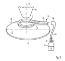
- Figure 2 is a perspective representation, in which substantially an outer casing 61 of the focusing lens 31 of the electron beam column 3, the gas supply arrangement 15 and the object 13 is schematically illustrated.
- Figure 3 is a plan view from bottom side onto a portion of the gas supply arrangement 15 and Figure 4 is a cross sectional view of the portion of the gas supply arrangement 15, shown in Figure 3 , taken along line IV-IV in Figure 3 .
- the gas supply arrangement 15 comprises an annular piping 63, which extends as a torus about a symmetry axis 64 or optical axis of the focusing lens 31 and thereby also about the beam path of the electron beam 5.
- a gas supply line 65 comprises a first end 66 which is connected via suitable lines 68 to a reservoir 74 containing a gas 71. Valves 72 or other devices such as heating or cooling devices are provided for controlling a flow of the gas 71 in the gas supply line 65.
- the gas supply line 65 opens into the annular piping 63.
- the gas supply line 65 is connected with the annular piping 63 such that the annular piping 63 is supported and/or carried by the gas supply line 65.
- the annular piping 63 is rigidly connected to the gas supply line 65.
- the annular piping 63 comprises a pipewall 67 which defines a substantially closed channel 69.
- the pipewall 67 surrounds the axis 64.
- the gas supply line 65 comprises a pipewall 75, which defines a channel 76, wherein the gas supply line 65 is connected to the annular piping such that the channel 76 opens into the annular channel 69.
- gas 71 can be supplied from the reservoir 74 through the gas supply line 65 into the annular channel 69, and the gas exits to the interaction region via the exit openings 73.
- the gas acts according to its desired function, such as for example neutralization of charging on the surface of the object, removal of material from the object or deposition of material on the object.
- the gas supply line 65 is pivotably or rotatably supported by a bearing 81 such that it is pivotable or rotatable about a longitudinal axis 83 of the gas supply line 65, as schematically illustrated in Figure 4 .
- the annular piping 63 is pivotable about the longitudinal axis 83.
- the pivot axis 83 extends parallel to the tilt axis 53 of the object holder, such that the annular piping is pivotable together, synchronously and/or in correspondence with the object, in particular when the object is to be arranged at a different tilt position relative to the particle beam columns.
- FIG 1 there are illustrated two pivot positions of the annular piping 63.
- the unbroken lines illustrate a pivot position, in which the side 71 of the annular piping 63, which faces the object, is arranged parallel to the surface of the object 13, when the object is arranged in the tilt position, which is shown in unbroken lines.
- the dashed lines illustrate a pivot position, in which the side 71 of the annular piping 63 is arranged parallel to the surface of the object 13, when the object is arranged in the tilt position, which is illustrated in dashed lines.
- Figure 5 shows, similarly as Figure 4 , a cross sectional representation of an exemplary embodiment of an annular piping for illustrating the underlying geometry and possible variants.
- the annular piping 63 extends around or surrounds an electron beam 5 and an ion beam 9.
- a principal plane of the ring piping 63 is oriented parallel to a surface of an object 13 to be processed.
- the electron beam 5 is oriented parallel to a surface normal of the object 13, whereas the ion beam 9 is oriented at an angle ⁇ of 54 ° to the surface normal.
- the object 13 is tiltable about a tilt axis 53, which is oriented perpendicular to the electron beam 5 and also perpendicular to the ion beam 9, whereas the annular piping 63 is tiltable or pivotable about a pivot axis 83, which is oriented parallel to the tilt axis 53.
- the annular piping 63 is arranged at a distance a from the surface of the object 13, and an inner diameter d of the ring of the annular piping 63 is selected such that both beams 5 and 9 can traverse the ring and scan a common region on the surface of the object.
- the annular piping 67 comprises a circular cross section, whereas the cross section of the annular piping, which is shown in Figure 4 , is rectangular. Also, other different geometries for the cross section of the annular piping are conceivable.
- openings 73 of the annular piping are oriented at an angle of 54° to a principal plane of the ring, such that gas, which flows out from the annular piping 67 via the openings 73, is directed to the intersection of both particle beams 5 and 9.
- the openings 73 of the annular piping are oriented at an angle of 90° relative to a principal plane of the ring, such that the outflowing gas is incident substantially perpendicular on the surface of the object.
- angle at which the openings of the annular piping are oriented relative to the principal plane of the ring, may be varied for controlling the flow of the gas towards the impingement location of the particle beams on the object in order to meet predefined criterions.
- the constant orientation of the annular piping relative to the object which is independent from the tilt position of the object relative to the focusing lens, results in a symmetrization of electric and magnetic fields, which are generated by the focusing lenses of the particle beam columns, such that the particle beams can be focused optimally onto the object, without being dependent from the tilt position of the object.
- a distance is provided between the tilt axis of the object holder and the pivot axis of the annular piping, which substantially corresponds to the distance between the surface of the object and the annular piping.
- the tilt axis of the object holder and the pivot axis of the annular piping may coincide or substantially coincide.
- the object holder and the annular piping may be pivotable about a common axis.
- the pivot axis of the annular piping may be located on the tilt axis of the object holder.
- the annular piping of the gas supply arrangement is not arranged stationary in the region between the objective lens and the object holder, but is removable from this region and can be inserted when needed.
- the gas supply line of the gas supply arrangement may traverse a vacuum chamber wall of the processing system, such that by longitudinally moving and/or pivoting the gas supply line from outside of the vacuum chamber wall, the annular piping is positionable or removable from the region between the objective lens and the object holder.
- the processing system comprises two particle beam columns, wherein one of which is configured as an electron beam column and the other is configured as an ion beam column.
- third or a plurality of further particle beam columns are provided.
- two particle beam columns are provided, wherein both of which are configured as electron beam columns or ion beam columns.
- only one particle beam column is provided, which is either configured as an electron beam column or an ion beam column.
Landscapes
- Chemical & Material Sciences (AREA)
- Analytical Chemistry (AREA)
- Physics & Mathematics (AREA)
- Engineering & Computer Science (AREA)
- Plasma & Fusion (AREA)
- Electron Sources, Ion Sources (AREA)
- Physical Vapour Deposition (AREA)
- Exposure And Positioning Against Photoresist Photosensitive Materials (AREA)
- Analysing Materials By The Use Of Radiation (AREA)
- Chemical Vapour Deposition (AREA)
Abstract

Description
- The present application claims priority of Patent Application No.
10 2011 018 460.0, filed April 21, 2011 in Germany, entitled "Processing System", the contents of which is hereby incorporated by reference in its entirety. - The present inventions relates to a processing system, which comprises a particle beam column having a focusing lens for directing a particle beam onto an interaction region on an object and a gas supply arrangement for supplying a gas to the interaction region. The gas, which is supplied to the interaction region, may have a function for neutralizing a space charge at the object. The space charge may be caused by the impingement of the particle beam onto the object. The gas, which is supplied to the interaction region may further have a function of a processing gas in such that it is activated by the particle beam and causes material deposition or material ablation in the interaction region.
- From prior art, there are known configurations of gas supply arrangements, which are integrated in a particle beam column. Examples for such configurations are known from
US 5,055,696 ,EP 2 091 066 A2 ,DE 102 08 043 A1 ,DE 10 2008 040 426 A1 ,DE 10 2007 054 074 A1 , andUS 2007/0246651 A1 . - A further particle beam column may be integrated in the configuration which comprises a particle beam column and a gas supply arrangement. The further particle beam column may direct a further particle beam onto the interaction region. For such configurations, it may be desirable that the object is tiltable relative to both particle beam columns. This, for example, allows to selectively direct either the first or the second particle beam perpendicular onto a surface of the object.
- Commonly known configurations of integrated particle beam columns and gas supply arrangements have disadvantages in that they are inflexible, they do not permit at the same time having small distances of the focusing lens of the particle beam column from the object and tilting the object. They also may have a negative influence on a symmetry of electric or magnetic fields of the focusing lens in the region of the object surface. Thereby, these configurations have a detrimental effect on a quality of the particle beam in the interaction region or on the gas supply to the interaction region.
- Accordingly, it is an object to provide a processing system, which allows an integration of a gas supply arrangement with a particle beam column, such that the above mentioned negative effects are at least partially mitigated.
- According to an embodiment, a processing system comprises a first particle beam column having a focusing lens for directing a first particle beam along a beam path of the first particle beam onto an interaction region. The interaction region may be defined as a focus region or an object region of the first particle beam and/or the second particle beam. The object region may be defined as a region, where a portion of the object is arranged for processing of the portion. The processing system may further comprise an object holder for arranging an object in the interaction region, wherein the object holder is configured to tilt the object relative to the first particle beam column about a tilting axis, wherein the tilting axis is oriented perpendicular or transverse to the direction of the particle beam. The processing system may further comprise a gas supply arrangement, which comprises an annular piping and a gas supply line. One end of the gas supply line may be coupleable to a gas reservoir. The gas supply line opens into the annular piping at a further end of the gas supply line. In other words, the gas supply line may be coupled to the annular piping at the further end of the gas supply line. Thereby, gas may be supplied from the gas reservoir into the annular piping.
- The annular piping extends annularly around the beam path of the first and/or a second particle beam. In other words, the annular piping may form a single closed loop surrounding the first and/or second particle beam. In particular, the annular piping may extend in the form of a circular annular shape around the beam path of the first particle beam and/or a second particle beam. The pivot axis of the annular piping may be aligned with or located within a principal plane of the annular piping. The principal plane of the annular piping may intersect the annular piping. The principal plane may divide the annular piping into two halves of substantially equal size. A longitudinal axis of a channel of the annular piping may be aligned with or located within the principal plane.
- The annular piping may be arranged between the focusing lens and the interaction region. On a side of the annular piping, which faces the interaction region, a plurality of exit openings are provided for the gas towards the interaction region. The plurality of exit openings may be arranged such that a gas flow of the gas is produced, wherein at least a portion of the gas flow is directed towards the interaction region when leaving the annular piping. Additionally or alternatively the gas exit openings may be arranged on an object side relative to a principal plane of the annular piping. Additionally or alternatively, the plurality of exit openings may face the interaction region and/or may be oriented towards the interaction region.
- The annular piping may comprise a holder, which is configured to pivot the annular piping about a pivot axis, which is parallel to a tilting axis of the object holder. The holder may be arranged at the gas supply line, the annular piping and/or a linear section of the gas supply line. The holder may be configured to pivotably support the gas supply line, the annular piping and/or the linear section of the gas supply line. The pivot axis of the annular piping may be arranged at a distance from the tilt axis of the object holder. The pivot axis may be arranged along or arranged parallel to a longitudinal axis of the gas supply line or a longitudinal axis of a linear section of the gas supply line.
- Thereby, it is possible to pivot the angular piping of the gas supply arrangement when the object holder is being tilted relative to the particle beam column, such that a collision of the object with the gas supply arrangement is avoided even at small distances between the object and the gas supply arrangement. In particular, at each of a plurality of different tilt positions of the object holder, the annular piping may be orientable along a same orientation as the object. For example, the annular piping may extend parallel to a plane object surface, wherein this is possible for each of a plurality of different tilt positions of the object holder. This allows to provide at a plurality of different tilt positions of the object relative to the particle beam column, substantially constant configurations of electric and magnetic fields of the focusing lens, such that a focusing or a focus of the particle beam in the interaction region is largely independent from the tilt position of the object relative to the particle beam column. Also, parameters for supplying the gas may be largely independent from the tilt position of the object relative to the particle beam column.
- The annular piping may be supported or carried by the gas supply line. In addition to the gas supply line, no further structures may be provided, which support the annular piping or which are connected to the annular piping. A longitudinal axis of the gas supply line may be aligned with or located within the principal plane of the annular piping.
- The gas supply line may further comprise a linear section, which extends linearly. In particular, the linear section may extend along or parallel to the pivot axis. The linear section may comprise a straight longitudinal axis. The pivot axis may be arranged within a cross section of the gas supply line or within a cross section of the linear section of the gas supply line.
- The pivot axis may pass through a center of the cross section or through a portion of the cross section, which is located closest to the object among all portions within the cross section.
- According to an embodiment, the plurality of exit openings are be equally distributed, as seen along a circumferential direction of the annular piping. The openings may be arranged at equal distances or at substantially equal distances along the circumferential direction or along a perimeter of the annular piping.
- The exit openings may be gas exit openings for supplying gas to the interaction region on the object. For example, two, three, four or more exit openings, such as six, ten or even more exit openings may be provided. A number of exit openings may be less than 500 or less than 100. The exit openings may for example have a circular cross section or may be formed as slits, which extend along the circumferential direction of the annular piping. In particular, the plurality of exit openings, which are distributed along the circumferential direction, may also be in a form of one single annular opening, which continuously extends along a circumferential direction. The single annular opening may extend around the full perimeter of the annular piping.
- In practice, an inner diameter of the ring, i.e. a distance between opposite side walls of the annular piping, which face each other and which also face the beam path may be chosen as small as possible for enabling an arrangement of the exit opening close to the interaction region. The inner diameter may further be chosen as big as necessary for allowing one or more particle beams to pass through the ring towards the interaction region and also to allow a scanning of the one or more particle beams over a sufficiently large portion of the object. In some embodiments, the particle beam, which is directed onto the interaction region is deflected away from a symmetry axis or an optical axis of the focusing lens for scanning the beam, for example over the object.
- The pivot axis of the annular piping may coincide with the tilt axis of the object holder. In other words, the pivot axis of the annular piping may extend along the tilt axis of the object holder. According to embodiments, the pivot axis of the annular piping has a distance from the tilt axis of the object holder of more than 0.25 mm or of more than 1.0 mm. In particular, this distance may be selected such that it is equal to the distance between a surface of the object and the surface or area of the annular piping, which faces the object. The pivot axis of the annular piping may be oriented parallel to the tilt axis of the object holder.
- The forgoing as well as other advantageous features will be more apparent from the following detailed description of exemplary embodiments with reference to the accompanying drawings. It is noted that not all possible embodiments necessarily exhibit each and every, or any, of the advantages identified herein.
- Figure 1
- is a schematic illustration of a processing system according to an exemplary embodiment;
- Figure 2
- is a perspective view of a portion of the processing system shown in
Figure 1 ; - Figure 3
- is a plan view from bottom side showing the gas supply arrangement of the processing system illustrated in
Figures 1 and2 ; - Figure 4
- is a cross section of the gas supply arrangement, illustrated in
Figure 3 along line IV-IV; and - Figure 5
- is a cross section of the gas supply arrangement according to a further exemplary embodiment.
- In the exemplary embodiments described below, components that are alike in function and structure are designated as far as possible by alike reference numerals. Therefore, to understand the features of the individual components of a specific embodiment, the descriptions of other embodiments and of the summary should be referred to.
-
Figure 1 is a schematic illustration of an exemplary embodiment of aprocessing system 1. Theprocessing system 1 comprises two particle beam columns. The two particle beam columns consist of anelectron beam column 3 for generating anelectron beam 5 and an ion beam column 7 for generating anion beam 9. Each of the beams is directed to aninteraction region 11. In theinteraction region 11, a surface of anobject 13 to be processed is arranged. Theobject 13 to be processed may for example be asemiconductor wafer 13. - The processing of the
object 13 may comprise a plurality of steps: for example, theelectron beam column 3 may be operated as an electron microscope for generating an electron microscopical image of the portion of the object which is arranged in the interaction region. To this end, theelectron beam 5 is directed as a primary beam onto theobject 13 for generating secondary particles, such as back-scattered electrons and secondary electrons. The back-scattered electrons and/or secondary electrons are detected by one or more detectors, such as an electron detector, for generating an electron microscopic image. - The
electron beam 5, which is directed onto the surface of theobject 13, may cause a local electrical charging on the object surface. In some applications, it is desirable to reduce such a charging. To this end, agas supply arrangement 15 is provided. With thisgas supply arrangement 15, it is possible to supply to the interaction region 11 a gas, such as nitrogen, oxygen, air and/or water vapor. The gas may be ionized by the electron beam. The ionized gas may neutralize charges, which are located on the object surface. - The processing of the
object 13 may further be performed with the ion beam column 7. The ion beam column 7 may be used to deposit or ablate material in theinteraction region 11 of theobject 13. - The ablation of material may be caused by the
ion beam 9 impinging on theobject 13 and removing single atoms or groups of atoms from theobject 13. In many cases, the ablation of material is performed by using a process gas, such as xenon difluoride, iodine, chlorine or water vapor. The process gas is supplied to the interaction region and is excited by the ion beam. The process gas establishes chemical bonds with atoms or molecules of theobject 13 and removes the atoms or molecules from theobject 13. The thereby required process gas may also be supplied via thegas supply arrangement 15 to theinteraction region 11. - The deposition of material on the object may be performed such that the process gas is supplied to the interaction region and activated by the ion beam such that decomposition products of molecules of the process gas are deposited at the object. Examples for such process gases are tungsten hexacarbonyl, phenanthrene, silan compounds, dimethylacetylacetonategold and methylcyclopentadienyltrimethylplatinum. Also, the supply of such a process gas may be performed with the
gas supply arrangement 15. - Furthermore, it is possible to use ions of the
ion beam 9 as primary particles for acquiring an image of theobject 13 in theinteraction region 11, wherein the ions remove secondary particles from the object, such as further ions and electrons, which then are detected. Additionally or alternatively, it is possible, to excite a process gas in theinteraction region 11 with theelectron beam 5 for performing a deposition of material on the object or an ablation of material from the object. - The
electron beam column 3 comprises anelectron source 21 having acathode 23 and ananode 25, one ormore condenser lenses 27 for generating theelectron beam 5. Theelectron beam column 3 further comprises anelectron detector 29, which, in the illustrated example, is arranged within the electron beam column. Theelectron beam column 3 further comprises anobjective lens 31 for directing and/or focusing theelectron beam 5 onto theinteraction region 11. Theelectron detector 29 is configured to detect secondary electrons and/or back-scattered electrons for acquiring an electron microscopic image of the object portion in theinteraction region 11. In the illustrated example, theelectron detector 29 is arranged within theelectron beam column 3. However, it is also conceivable that theelectron detector 29 is arranged outside of theelectron beam column 3. Theelectron detector 29 is arranged such that electrons, which emanate from theinteraction region 11 are detectable. - The
electron beam column 3 further comprises a beam deflector 33 for varying an impingement location of theelectron beam 5 on the object within theinteraction region 11. In particular, by operating the beam deflector 33, it is possible to schematically scan theelectron beam 5 over the surface of theobject 13 and to simultaneously detect secondary electrons and/or back-scattered electrons with theelectron detector 29 for acquiring an electron microscopic image of the object. - The ion beam column 7 comprises an
ion source 37 andelectrodes 41 for forming and accelerating theion beam 9. The ion beam column 7 further comprises focusing coils or focusingelectrodes 43 for focusing theion beam 9 within theinteraction region 11. The ion beam column 7 further comprises abeam deflector 45 for varying an impingement location of theion beam 9 on theobject 13 within theinteraction region 11. - The
object 13 is held by anobject holder 51, such that a portion of the surface of theobject 13 is arranged in theinteraction region 11. Theobject holder 51 is further configured to tilt theobject 13 about atilt axis 43, which is oriented perpendicular to the drawing plane ofFigure 1 , such that the object is arrangeable at a plurality of tilt positions relative to theelectron beam column 3 and the ion beam column 7, respectively. In the tilt position of theobject 13 and theobject holder 51, which is illustrated inFigure 1 with unbroken lines, the surface of theobject 13 is oriented relative to theelectron beam column 3 such that theelectron beam 5 impinges substantially perpendicular onto the surface of the object. Theion beam 9, which is oriented at an angle of for example 40° to 60° relative to theelectron beam 5 then impinges obliquely onto the surface of theobject 13. According to an embodiment, the angle between theion beam 9 and theelectron beam 5 is 54°. However, it is also conceivable, that this angle is significantly greater than 60°. According to a further possible embodiment, this angle amounts to 90°. - In the tilt position of the
object 13 and theobject holder 51, which is illustrated inFigure 1 in dashed lines, the object is arranged relative to the ion beam column 7 such that theion beam 9 impinges substantially perpendicularly onto the surface of theobject 13, whereas theelectron beam 5 impinges obliquely onto the surface. - The tilting of the object relative to the
particle beam columns 3, 7 is desirable for forming and inspecting three-dimensional structures on the object. For example, a hole which extends perpendicularly or vertically into the object, can be prepared by irradiating the object with theion beam 9 in the tilt position, which is illustrated inFigure 1 in dashed lines. In the tilt position, which is illustrated inFigure 1 in unbroken lines, the hole can be inspected with the electron beam. - A configuration of the
gas supply arrangement 15 is described in the following with reference toFigures 2 to 5 . -
Figure 2 is a perspective representation, in which substantially anouter casing 61 of the focusinglens 31 of theelectron beam column 3, thegas supply arrangement 15 and theobject 13 is schematically illustrated. -
Figure 3 is a plan view from bottom side onto a portion of thegas supply arrangement 15 andFigure 4 is a cross sectional view of the portion of thegas supply arrangement 15, shown inFigure 3 , taken along line IV-IV inFigure 3 . - The
gas supply arrangement 15 comprises anannular piping 63, which extends as a torus about asymmetry axis 64 or optical axis of the focusinglens 31 and thereby also about the beam path of theelectron beam 5. Agas supply line 65 comprises afirst end 66 which is connected viasuitable lines 68 to areservoir 74 containing agas 71.Valves 72 or other devices such as heating or cooling devices are provided for controlling a flow of thegas 71 in thegas supply line 65. At theother end 75 of thegas supply line 65, thegas supply line 65 opens into theannular piping 63. Thegas supply line 65 is connected with theannular piping 63 such that theannular piping 63 is supported and/or carried by thegas supply line 65. Theannular piping 63 is rigidly connected to thegas supply line 65. - The
annular piping 63 comprises apipewall 67 which defines a substantially closedchannel 69. Thepipewall 67 surrounds theaxis 64. On aside 61 of thewall 67, which faces theobject 13, thewall 67 comprises a plurality ofopenings 73, which open into thechannel 69. Thegas supply line 65 comprises apipewall 75, which defines achannel 76, wherein thegas supply line 65 is connected to the annular piping such that thechannel 76 opens into theannular channel 69. Thereby,gas 71 can be supplied from thereservoir 74 through thegas supply line 65 into theannular channel 69, and the gas exits to the interaction region via theexit openings 73. There, the gas acts according to its desired function, such as for example neutralization of charging on the surface of the object, removal of material from the object or deposition of material on the object. - The
gas supply line 65 is pivotably or rotatably supported by a bearing 81 such that it is pivotable or rotatable about alongitudinal axis 83 of thegas supply line 65, as schematically illustrated inFigure 4 . Thereby, also theannular piping 63 is pivotable about thelongitudinal axis 83. - The
pivot axis 83 extends parallel to thetilt axis 53 of the object holder, such that the annular piping is pivotable together, synchronously and/or in correspondence with the object, in particular when the object is to be arranged at a different tilt position relative to the particle beam columns. InFigure 1 , there are illustrated two pivot positions of theannular piping 63. The unbroken lines illustrate a pivot position, in which theside 71 of theannular piping 63, which faces the object, is arranged parallel to the surface of theobject 13, when the object is arranged in the tilt position, which is shown in unbroken lines. The dashed lines illustrate a pivot position, in which theside 71 of theannular piping 63 is arranged parallel to the surface of theobject 13, when the object is arranged in the tilt position, which is illustrated in dashed lines. -
Figure 5 shows, similarly asFigure 4 , a cross sectional representation of an exemplary embodiment of an annular piping for illustrating the underlying geometry and possible variants. Theannular piping 63 extends around or surrounds anelectron beam 5 and anion beam 9. A principal plane of the ring piping 63 is oriented parallel to a surface of anobject 13 to be processed. As shown inFigure 5 , theelectron beam 5 is oriented parallel to a surface normal of theobject 13, whereas theion beam 9 is oriented at an angle α of 54 ° to the surface normal. Also in the exemplary embodiment, which is illustrated inFigure 5 , theobject 13 is tiltable about atilt axis 53, which is oriented perpendicular to theelectron beam 5 and also perpendicular to theion beam 9, whereas theannular piping 63 is tiltable or pivotable about apivot axis 83, which is oriented parallel to thetilt axis 53. - In the configuration, which is shown in
Figure 5 , theannular piping 63 is arranged at a distance a from the surface of theobject 13, and an inner diameter d of the ring of theannular piping 63 is selected such that bothbeams - In the example, which is illustrated in
Figure 5 , theannular piping 67 comprises a circular cross section, whereas the cross section of the annular piping, which is shown inFigure 4 , is rectangular. Also, other different geometries for the cross section of the annular piping are conceivable. - Furthermore,
openings 73 of the annular piping, which are shown inFigure 5 , are oriented at an angle of 54° to a principal plane of the ring, such that gas, which flows out from theannular piping 67 via theopenings 73, is directed to the intersection of bothparticle beams Figure 4 , theopenings 73 of the annular piping are oriented at an angle of 90° relative to a principal plane of the ring, such that the outflowing gas is incident substantially perpendicular on the surface of the object. It is obvious, that the angle, at which the openings of the annular piping are oriented relative to the principal plane of the ring, may be varied for controlling the flow of the gas towards the impingement location of the particle beams on the object in order to meet predefined criterions. - Through the pivoting of the annular piping in correspondence or synchronously with the tilting of the object, it is possible to arrange the object particularly close to the particle beam columns and to tilt the object without risking a collision between the gas supply arrangement and the object. Thereby, a required installation space for the annular piping is comparatively small. Furthermore, also the distance of the annular piping from the object is comparatively small, such that the process gas is emitted from the gas supply arrangement at a location close to the object and the process gas can be sufficiently supplied to the object. Furthermore, the constant orientation of the annular piping relative to the object, which is independent from the tilt position of the object relative to the focusing lens, results in a symmetrization of electric and magnetic fields, which are generated by the focusing lenses of the particle beam columns, such that the particle beams can be focused optimally onto the object, without being dependent from the tilt position of the object.
- In the exemplary embodiments described above, a distance is provided between the tilt axis of the object holder and the pivot axis of the annular piping, which substantially corresponds to the distance between the surface of the object and the annular piping. However, it is also conceivable to provide different distances between the tilt axis of the object holder and the pivot axis of the annular piping, which are greater or smaller than the distance between the surface of the object and the annular piping. For example, the tilt axis of the object holder and the pivot axis of the annular piping may coincide or substantially coincide. Thereby, the object holder and the annular piping may be pivotable about a common axis. In other words, the pivot axis of the annular piping may be located on the tilt axis of the object holder.
- It is also conceivable, that the annular piping of the gas supply arrangement is not arranged stationary in the region between the objective lens and the object holder, but is removable from this region and can be inserted when needed. To this end, the gas supply line of the gas supply arrangement may traverse a vacuum chamber wall of the processing system, such that by longitudinally moving and/or pivoting the gas supply line from outside of the vacuum chamber wall, the annular piping is positionable or removable from the region between the objective lens and the object holder.
- In the exemplary embodiments described above, the processing system comprises two particle beam columns, wherein one of which is configured as an electron beam column and the other is configured as an ion beam column. However, it is also conceivable, that third or a plurality of further particle beam columns are provided. It is further conceivable that two particle beam columns are provided, wherein both of which are configured as electron beam columns or ion beam columns. It is further conceivable that only one particle beam column is provided, which is either configured as an electron beam column or an ion beam column.
- While the foregoing disclosure has been described with respect to certain exemplary embodiments thereof, it is evident that many alternatives, modifications and variations will be apparent to those skilled in the art. Accordingly, the exemplary embodiments set forth herein are intended to be illustrative and not limiting in any way. Various changes may be made without departing from the spirit and scope of the present disclosure as defined in the following claims.
Claims (14)
- A processing system, comprising:a first particle beam column (3) having a focusing lens (31) for focusing a first particle beam (5) along a beam path of the first particle beam (5) onto an interaction region (11);an object holder (51) for arranging an object (13) in the interaction region (11), wherein the object holder (51) is configured to tilt the object (13) relative to the first particle beam column (3) about a tilt axis (53) of the object holder (51), wherein the tilt axis (53) is oriented transverse to a direction of the beam path of the first particle beam (5); anda gas supply arrangement (15), which comprises an annular piping (63) and a gas supply line (65);wherein an end (66) of the gas supply line (65) is coupleable to a gas reservoir (74) and at a further end (75) of the gas supply line (65), the gas supply line (65) opens into the annular piping (63) for supplying gas (71) from the gas reservoir (74) to the annular piping (63);wherein the annular piping (63) extends annularly around the beam path of the first particle beam (5) between the focusing lens (31) and the interaction region (11);wherein the annular piping (63) comprises on a side, which faces the interaction region (11), a plurality of exit openings (73) for the gas (71) towards the interaction region (11); andwherein the annular piping (63) comprises a holder (81), which is configured to pivot the annular piping (63) about a pivot axis (83) of the annular piping (63), wherein the pivot axis (83) is parallel to the tilt axis (53) of the object holder (51).
- The processing system according to claim 1, wherein the gas supply line (65) comprises a section, which extends linearly along the pivot axis (83).
- The processing system according to claim 1 or 2, wherein the annular piping (63) is supported by the gas supply line (65).
- The processing system according to any one of claims 1 to 3, wherein the exit openings (73) are equally distributed, as seen along a circumferential direction of the annular piping (63).
- The processing system according to any one of claims 1 to 4, wherein an inner diameter (d) of the annular piping (63), measured in a direction transverse to the pivot axis (83) of the annular piping (63), is greater than 0.1 mm, or greater than 0.5 mm.
- The processing system according to any one of claims 1 to 5, wherein an inner diameter (d) of the annular piping (63), measured in a direction transverse to the pivot axis (83) of the annular piping (63) is smaller than 10.0 mm, or smaller than 5.0 mm.
- The processing system according to any one of claims 1 to 6, wherein a distance (a) between the tilt axis (53) of the object holder (51) and a side of the annular piping (63), which is averted from the object holder (51), when the annular piping (63) is oriented parallel to the object (13), is greater than 0.5 mm, or greater than 1.0 mm.
- The processing system according to any one of claims 1 to 7, wherein a distance (a) between the tilt axis (53) of the object holder (51) and a side of the annular piping (63), which is averted from the object holder (51), when the annular piping (63) is oriented parallel to the object (13), is smaller than 4.0 mm, or smaller than 2.0 mm.
- The processing system according to any one of claims 1 to 8, wherein the first particle beam column (3) is configured to direct an electron beam or an ion beam onto the interaction region (11).
- The processing system according to any one of claims 1 to 9, further comprising a second particle beam column (7) having a focusing lens (43) for directing a second particle beam (9) along a beam path of the second particle beam (9) onto the interaction region (11);
wherein the annular piping (63) also extends annularly around the beam path of the second particle beam (9) and is arranged between the focusing lens (43) of the second particle beam column (7) and the interaction region (11). - The processing system according to claim 10, wherein a direction of the beam path of the second particle beam (9) is oriented perpendicular to the tilt axis (53) of the object holder (51).
- The processing system according to claim 10 or 11, wherein the second particle beam column (7) is configured to direct an electron beam or an ion beam onto the interaction region (11).
- The processing system according to any one of claims 10 to 12, wherein the first particle beam column (3) is configured to direct an electron beam onto the interaction region (11), and the second particle beam column (7) is configured to direct an ion beam onto the interaction region (11).
- The processing system according to any one of claims 1 to 13, wherein the annular piping (63) extends in the form of a circular annular shape around the beam path of the first particle beam (5).
Applications Claiming Priority (1)
| Application Number | Priority Date | Filing Date | Title |
|---|---|---|---|
| DE102011018460A DE102011018460A1 (en) | 2011-04-21 | 2011-04-21 | processing system |
Publications (2)
| Publication Number | Publication Date |
|---|---|
| EP2515321A1 true EP2515321A1 (en) | 2012-10-24 |
| EP2515321B1 EP2515321B1 (en) | 2014-04-16 |
Family
ID=46245763
Family Applications (1)
| Application Number | Title | Priority Date | Filing Date |
|---|---|---|---|
| EP20120002787 Active EP2515321B1 (en) | 2011-04-21 | 2012-04-20 | Charged particle beam processing system with pivoting annular gas delivery system |
Country Status (4)
| Country | Link |
|---|---|
| US (1) | US8415644B2 (en) |
| EP (1) | EP2515321B1 (en) |
| CN (1) | CN102760649B (en) |
| DE (1) | DE102011018460A1 (en) |
Citations (9)
| Publication number | Priority date | Publication date | Assignee | Title |
|---|---|---|---|---|
| US5055696A (en) | 1988-08-29 | 1991-10-08 | Hitachi, Ltd. | Multilayered device micro etching method and system |
| US5851413A (en) * | 1996-06-19 | 1998-12-22 | Micrion Corporation | Gas delivery systems for particle beam processing |
| DE10208043A1 (en) | 2002-02-25 | 2003-09-11 | Leo Elektronenmikroskopie Gmbh | Material processing system, material processing method and gas supply therefor |
| US20070246651A1 (en) | 2005-12-16 | 2007-10-25 | Hirotami Koike | Charged particle beam apparatus |
| US20080302954A1 (en) * | 2005-11-07 | 2008-12-11 | Fibics Incorporated | Apparatus and Method for Surface Modification Using Charged Particle Beams |
| DE102007054074A1 (en) | 2007-11-13 | 2009-05-14 | Carl Zeiss Nts Gmbh | System for editing an object |
| EP2091066A2 (en) | 2008-02-18 | 2009-08-19 | Carl Zeiss NTS GmbH | Processing system |
| DE102008040426A1 (en) | 2008-07-15 | 2010-02-11 | Carl Zeiss Nts Gmbh | Method for examining surface of object using particle beam of particle beam device, involves arranging object in sample chamber, and supplying particle beam to predetermined location on surface of object |
| US20100051828A1 (en) * | 2008-09-01 | 2010-03-04 | Carl Zeiss Nts Gmbh | Processing system |
Family Cites Families (1)
| Publication number | Priority date | Publication date | Assignee | Title |
|---|---|---|---|---|
| US20050103272A1 (en) | 2002-02-25 | 2005-05-19 | Leo Elektronenmikroskopie Gmbh | Material processing system and method |
-
2011
- 2011-04-21 DE DE102011018460A patent/DE102011018460A1/en not_active Ceased
-
2012
- 2012-04-20 US US13/451,734 patent/US8415644B2/en active Active
- 2012-04-20 EP EP20120002787 patent/EP2515321B1/en active Active
- 2012-04-23 CN CN201210239469.1A patent/CN102760649B/en active Active
Patent Citations (10)
| Publication number | Priority date | Publication date | Assignee | Title |
|---|---|---|---|---|
| US5055696A (en) | 1988-08-29 | 1991-10-08 | Hitachi, Ltd. | Multilayered device micro etching method and system |
| US5851413A (en) * | 1996-06-19 | 1998-12-22 | Micrion Corporation | Gas delivery systems for particle beam processing |
| DE10208043A1 (en) | 2002-02-25 | 2003-09-11 | Leo Elektronenmikroskopie Gmbh | Material processing system, material processing method and gas supply therefor |
| US20080302954A1 (en) * | 2005-11-07 | 2008-12-11 | Fibics Incorporated | Apparatus and Method for Surface Modification Using Charged Particle Beams |
| US20070246651A1 (en) | 2005-12-16 | 2007-10-25 | Hirotami Koike | Charged particle beam apparatus |
| DE102007054074A1 (en) | 2007-11-13 | 2009-05-14 | Carl Zeiss Nts Gmbh | System for editing an object |
| US20090152460A1 (en) * | 2007-11-13 | 2009-06-18 | Carl Zeiss Nts Gmbh | System for Processing an Object |
| EP2091066A2 (en) | 2008-02-18 | 2009-08-19 | Carl Zeiss NTS GmbH | Processing system |
| DE102008040426A1 (en) | 2008-07-15 | 2010-02-11 | Carl Zeiss Nts Gmbh | Method for examining surface of object using particle beam of particle beam device, involves arranging object in sample chamber, and supplying particle beam to predetermined location on surface of object |
| US20100051828A1 (en) * | 2008-09-01 | 2010-03-04 | Carl Zeiss Nts Gmbh | Processing system |
Also Published As
| Publication number | Publication date |
|---|---|
| CN102760649B (en) | 2017-07-11 |
| US8415644B2 (en) | 2013-04-09 |
| US20120267545A1 (en) | 2012-10-25 |
| DE102011018460A1 (en) | 2012-10-25 |
| EP2515321B1 (en) | 2014-04-16 |
| CN102760649A (en) | 2012-10-31 |
Similar Documents
| Publication | Publication Date | Title |
|---|---|---|
| TWI709992B (en) | Method for inspecting a specimen and charged particle multi-beam device | |
| JP5087366B2 (en) | Gas field ion source for multipurpose applications | |
| EP1577927B1 (en) | Charged particle beam system | |
| US7968855B2 (en) | Dual mode gas field ion source | |
| JP6118846B2 (en) | Composite focused ion beam apparatus and sample processing method using the same | |
| JP5498955B2 (en) | Apparatus and method for analyzing and / or processing samples | |
| US7629578B2 (en) | Charged particle beam device | |
| NL1037117C2 (en) | Method and device for examining a surface of an object. | |
| JP7692034B2 (en) | Apparatus and method for analyzing and/or processing a sample with a particle beam - Patents.com | |
| US20100108902A1 (en) | Dual mode gas field ion source | |
| JP2008112999A (en) | Charged particle exposure equipment | |
| JP2015043343A (en) | Composite convergent ion beam device | |
| JP2015525951A (en) | Multi-ion source | |
| US7923702B2 (en) | System and method for processing an object | |
| EP2515321B1 (en) | Charged particle beam processing system with pivoting annular gas delivery system | |
| US11199480B2 (en) | Thin-sample-piece fabricating device and thin-sample-piece fabricating method | |
| JP2010114082A (en) | Gas electric field ion source of dual mode | |
| US6992288B2 (en) | Apparatus and method for directing gas towards a specimen | |
| JP4988308B2 (en) | Gas amplification type detector and electron beam application apparatus using the same | |
| JP7182003B2 (en) | charged particle beam system | |
| KR102695451B1 (en) | Specimen treating apparatus using charged particles | |
| JP7117107B2 (en) | Impact ionization source | |
| JP2007165210A (en) | Charged particle beam equipment | |
| JP2024141055A (en) | Nozzle for particle beam assisted processing device and particle beam assisted processing device |
Legal Events
| Date | Code | Title | Description |
|---|---|---|---|
| PUAI | Public reference made under article 153(3) epc to a published international application that has entered the european phase |
Free format text: ORIGINAL CODE: 0009012 |
|
| AK | Designated contracting states |
Kind code of ref document: A1 Designated state(s): AL AT BE BG CH CY CZ DE DK EE ES FI FR GB GR HR HU IE IS IT LI LT LU LV MC MK MT NL NO PL PT RO RS SE SI SK SM TR |
|
| AX | Request for extension of the european patent |
Extension state: BA ME |
|
| 17P | Request for examination filed |
Effective date: 20130422 |
|
| GRAP | Despatch of communication of intention to grant a patent |
Free format text: ORIGINAL CODE: EPIDOSNIGR1 |
|
| RIC1 | Information provided on ipc code assigned before grant |
Ipc: H01J 37/305 20060101AFI20130527BHEP Ipc: H01J 37/30 20060101ALI20130527BHEP Ipc: H01J 37/317 20060101ALI20130527BHEP |
|
| INTG | Intention to grant announced |
Effective date: 20130618 |
|
| GRAP | Despatch of communication of intention to grant a patent |
Free format text: ORIGINAL CODE: EPIDOSNIGR1 |
|
| GRAP | Despatch of communication of intention to grant a patent |
Free format text: ORIGINAL CODE: EPIDOSNIGR1 |
|
| INTG | Intention to grant announced |
Effective date: 20131120 |
|
| INTG | Intention to grant announced |
Effective date: 20131217 |
|
| GRAS | Grant fee paid |
Free format text: ORIGINAL CODE: EPIDOSNIGR3 |
|
| GRAA | (expected) grant |
Free format text: ORIGINAL CODE: 0009210 |
|
| RAP1 | Party data changed (applicant data changed or rights of an application transferred) |
Owner name: CARL ZEISS MICROSCOPY GMBH |
|
| AK | Designated contracting states |
Kind code of ref document: B1 Designated state(s): AL AT BE BG CH CY CZ DE DK EE ES FI FR GB GR HR HU IE IS IT LI LT LU LV MC MK MT NL NO PL PT RO RS SE SI SK SM TR |
|
| REG | Reference to a national code |
Ref country code: GB Ref legal event code: FG4D |
|
| REG | Reference to a national code |
Ref country code: CH Ref legal event code: EP |
|
| REG | Reference to a national code |
Ref country code: AT Ref legal event code: REF Ref document number: 662998 Country of ref document: AT Kind code of ref document: T Effective date: 20140515 |
|
| REG | Reference to a national code |
Ref country code: IE Ref legal event code: FG4D |
|
| REG | Reference to a national code |
Ref country code: DE Ref legal event code: R096 Ref document number: 602012001375 Country of ref document: DE Effective date: 20140528 |
|
| REG | Reference to a national code |
Ref country code: NL Ref legal event code: T3 |
|
| REG | Reference to a national code |
Ref country code: AT Ref legal event code: MK05 Ref document number: 662998 Country of ref document: AT Kind code of ref document: T Effective date: 20140416 |
|
| REG | Reference to a national code |
Ref country code: LT Ref legal event code: MG4D |
|
| PG25 | Lapsed in a contracting state [announced via postgrant information from national office to epo] |
Ref country code: CY Free format text: LAPSE BECAUSE OF FAILURE TO SUBMIT A TRANSLATION OF THE DESCRIPTION OR TO PAY THE FEE WITHIN THE PRESCRIBED TIME-LIMIT Effective date: 20140416 Ref country code: IS Free format text: LAPSE BECAUSE OF FAILURE TO SUBMIT A TRANSLATION OF THE DESCRIPTION OR TO PAY THE FEE WITHIN THE PRESCRIBED TIME-LIMIT Effective date: 20140816 Ref country code: BG Free format text: LAPSE BECAUSE OF FAILURE TO SUBMIT A TRANSLATION OF THE DESCRIPTION OR TO PAY THE FEE WITHIN THE PRESCRIBED TIME-LIMIT Effective date: 20140716 Ref country code: FI Free format text: LAPSE BECAUSE OF FAILURE TO SUBMIT A TRANSLATION OF THE DESCRIPTION OR TO PAY THE FEE WITHIN THE PRESCRIBED TIME-LIMIT Effective date: 20140416 Ref country code: GR Free format text: LAPSE BECAUSE OF FAILURE TO SUBMIT A TRANSLATION OF THE DESCRIPTION OR TO PAY THE FEE WITHIN THE PRESCRIBED TIME-LIMIT Effective date: 20140717 Ref country code: LT Free format text: LAPSE BECAUSE OF FAILURE TO SUBMIT A TRANSLATION OF THE DESCRIPTION OR TO PAY THE FEE WITHIN THE PRESCRIBED TIME-LIMIT Effective date: 20140416 Ref country code: NO Free format text: LAPSE BECAUSE OF FAILURE TO SUBMIT A TRANSLATION OF THE DESCRIPTION OR TO PAY THE FEE WITHIN THE PRESCRIBED TIME-LIMIT Effective date: 20140716 |
|
| PG25 | Lapsed in a contracting state [announced via postgrant information from national office to epo] |
Ref country code: RS Free format text: LAPSE BECAUSE OF FAILURE TO SUBMIT A TRANSLATION OF THE DESCRIPTION OR TO PAY THE FEE WITHIN THE PRESCRIBED TIME-LIMIT Effective date: 20140416 Ref country code: ES Free format text: LAPSE BECAUSE OF FAILURE TO SUBMIT A TRANSLATION OF THE DESCRIPTION OR TO PAY THE FEE WITHIN THE PRESCRIBED TIME-LIMIT Effective date: 20140416 Ref country code: AT Free format text: LAPSE BECAUSE OF FAILURE TO SUBMIT A TRANSLATION OF THE DESCRIPTION OR TO PAY THE FEE WITHIN THE PRESCRIBED TIME-LIMIT Effective date: 20140416 Ref country code: HR Free format text: LAPSE BECAUSE OF FAILURE TO SUBMIT A TRANSLATION OF THE DESCRIPTION OR TO PAY THE FEE WITHIN THE PRESCRIBED TIME-LIMIT Effective date: 20140416 Ref country code: SE Free format text: LAPSE BECAUSE OF FAILURE TO SUBMIT A TRANSLATION OF THE DESCRIPTION OR TO PAY THE FEE WITHIN THE PRESCRIBED TIME-LIMIT Effective date: 20140416 Ref country code: LV Free format text: LAPSE BECAUSE OF FAILURE TO SUBMIT A TRANSLATION OF THE DESCRIPTION OR TO PAY THE FEE WITHIN THE PRESCRIBED TIME-LIMIT Effective date: 20140416 Ref country code: PL Free format text: LAPSE BECAUSE OF FAILURE TO SUBMIT A TRANSLATION OF THE DESCRIPTION OR TO PAY THE FEE WITHIN THE PRESCRIBED TIME-LIMIT Effective date: 20140416 |
|
| PG25 | Lapsed in a contracting state [announced via postgrant information from national office to epo] |
Ref country code: PT Free format text: LAPSE BECAUSE OF FAILURE TO SUBMIT A TRANSLATION OF THE DESCRIPTION OR TO PAY THE FEE WITHIN THE PRESCRIBED TIME-LIMIT Effective date: 20140818 |
|
| REG | Reference to a national code |
Ref country code: DE Ref legal event code: R097 Ref document number: 602012001375 Country of ref document: DE |
|
| REG | Reference to a national code |
Ref country code: IE Ref legal event code: MM4A |
|
| PG25 | Lapsed in a contracting state [announced via postgrant information from national office to epo] |
Ref country code: SK Free format text: LAPSE BECAUSE OF FAILURE TO SUBMIT A TRANSLATION OF THE DESCRIPTION OR TO PAY THE FEE WITHIN THE PRESCRIBED TIME-LIMIT Effective date: 20140416 Ref country code: MC Free format text: LAPSE BECAUSE OF FAILURE TO SUBMIT A TRANSLATION OF THE DESCRIPTION OR TO PAY THE FEE WITHIN THE PRESCRIBED TIME-LIMIT Effective date: 20140416 Ref country code: DK Free format text: LAPSE BECAUSE OF FAILURE TO SUBMIT A TRANSLATION OF THE DESCRIPTION OR TO PAY THE FEE WITHIN THE PRESCRIBED TIME-LIMIT Effective date: 20140416 Ref country code: EE Free format text: LAPSE BECAUSE OF FAILURE TO SUBMIT A TRANSLATION OF THE DESCRIPTION OR TO PAY THE FEE WITHIN THE PRESCRIBED TIME-LIMIT Effective date: 20140416 Ref country code: BE Free format text: LAPSE BECAUSE OF FAILURE TO SUBMIT A TRANSLATION OF THE DESCRIPTION OR TO PAY THE FEE WITHIN THE PRESCRIBED TIME-LIMIT Effective date: 20140416 Ref country code: RO Free format text: LAPSE BECAUSE OF FAILURE TO SUBMIT A TRANSLATION OF THE DESCRIPTION OR TO PAY THE FEE WITHIN THE PRESCRIBED TIME-LIMIT Effective date: 20140416 |
|
| PLBE | No opposition filed within time limit |
Free format text: ORIGINAL CODE: 0009261 |
|
| STAA | Information on the status of an ep patent application or granted ep patent |
Free format text: STATUS: NO OPPOSITION FILED WITHIN TIME LIMIT |
|
| REG | Reference to a national code |
Ref country code: FR Ref legal event code: ST Effective date: 20150213 |
|
| 26N | No opposition filed |
Effective date: 20150119 |
|
| PG25 | Lapsed in a contracting state [announced via postgrant information from national office to epo] |
Ref country code: IT Free format text: LAPSE BECAUSE OF FAILURE TO SUBMIT A TRANSLATION OF THE DESCRIPTION OR TO PAY THE FEE WITHIN THE PRESCRIBED TIME-LIMIT Effective date: 20140416 |
|
| PG25 | Lapsed in a contracting state [announced via postgrant information from national office to epo] |
Ref country code: IE Free format text: LAPSE BECAUSE OF NON-PAYMENT OF DUE FEES Effective date: 20140420 |
|
| REG | Reference to a national code |
Ref country code: DE Ref legal event code: R097 Ref document number: 602012001375 Country of ref document: DE Effective date: 20150119 |
|
| PG25 | Lapsed in a contracting state [announced via postgrant information from national office to epo] |
Ref country code: FR Free format text: LAPSE BECAUSE OF NON-PAYMENT OF DUE FEES Effective date: 20140616 |
|
| PG25 | Lapsed in a contracting state [announced via postgrant information from national office to epo] |
Ref country code: SI Free format text: LAPSE BECAUSE OF FAILURE TO SUBMIT A TRANSLATION OF THE DESCRIPTION OR TO PAY THE FEE WITHIN THE PRESCRIBED TIME-LIMIT Effective date: 20140416 |
|
| REG | Reference to a national code |
Ref country code: CH Ref legal event code: PL |
|
| PG25 | Lapsed in a contracting state [announced via postgrant information from national office to epo] |
Ref country code: LI Free format text: LAPSE BECAUSE OF NON-PAYMENT OF DUE FEES Effective date: 20150430 Ref country code: CH Free format text: LAPSE BECAUSE OF NON-PAYMENT OF DUE FEES Effective date: 20150430 |
|
| PG25 | Lapsed in a contracting state [announced via postgrant information from national office to epo] |
Ref country code: MT Free format text: LAPSE BECAUSE OF FAILURE TO SUBMIT A TRANSLATION OF THE DESCRIPTION OR TO PAY THE FEE WITHIN THE PRESCRIBED TIME-LIMIT Effective date: 20140416 |
|
| PG25 | Lapsed in a contracting state [announced via postgrant information from national office to epo] |
Ref country code: SM Free format text: LAPSE BECAUSE OF FAILURE TO SUBMIT A TRANSLATION OF THE DESCRIPTION OR TO PAY THE FEE WITHIN THE PRESCRIBED TIME-LIMIT Effective date: 20140416 |
|
| PG25 | Lapsed in a contracting state [announced via postgrant information from national office to epo] |
Ref country code: HU Free format text: LAPSE BECAUSE OF FAILURE TO SUBMIT A TRANSLATION OF THE DESCRIPTION OR TO PAY THE FEE WITHIN THE PRESCRIBED TIME-LIMIT; INVALID AB INITIO Effective date: 20120420 Ref country code: TR Free format text: LAPSE BECAUSE OF FAILURE TO SUBMIT A TRANSLATION OF THE DESCRIPTION OR TO PAY THE FEE WITHIN THE PRESCRIBED TIME-LIMIT Effective date: 20140416 Ref country code: LU Free format text: LAPSE BECAUSE OF NON-PAYMENT OF DUE FEES Effective date: 20140420 |
|
| GBPC | Gb: european patent ceased through non-payment of renewal fee |
Effective date: 20160420 |
|
| PG25 | Lapsed in a contracting state [announced via postgrant information from national office to epo] |
Ref country code: GB Free format text: LAPSE BECAUSE OF NON-PAYMENT OF DUE FEES Effective date: 20160420 |
|
| PG25 | Lapsed in a contracting state [announced via postgrant information from national office to epo] |
Ref country code: MK Free format text: LAPSE BECAUSE OF FAILURE TO SUBMIT A TRANSLATION OF THE DESCRIPTION OR TO PAY THE FEE WITHIN THE PRESCRIBED TIME-LIMIT Effective date: 20140416 |
|
| PG25 | Lapsed in a contracting state [announced via postgrant information from national office to epo] |
Ref country code: AL Free format text: LAPSE BECAUSE OF FAILURE TO SUBMIT A TRANSLATION OF THE DESCRIPTION OR TO PAY THE FEE WITHIN THE PRESCRIBED TIME-LIMIT Effective date: 20140416 |
|
| PGFP | Annual fee paid to national office [announced via postgrant information from national office to epo] |
Ref country code: NL Payment date: 20210420 Year of fee payment: 10 |
|
| REG | Reference to a national code |
Ref country code: NL Ref legal event code: MM Effective date: 20220501 |
|
| PG25 | Lapsed in a contracting state [announced via postgrant information from national office to epo] |
Ref country code: NL Free format text: LAPSE BECAUSE OF NON-PAYMENT OF DUE FEES Effective date: 20220501 |
|
| PGFP | Annual fee paid to national office [announced via postgrant information from national office to epo] |
Ref country code: DE Payment date: 20250422 Year of fee payment: 14 |
|
| PGFP | Annual fee paid to national office [announced via postgrant information from national office to epo] |
Ref country code: CZ Payment date: 20250414 Year of fee payment: 14 |