EP2091066A2 - Processing system - Google Patents
Processing system Download PDFInfo
- Publication number
- EP2091066A2 EP2091066A2 EP20090002286 EP09002286A EP2091066A2 EP 2091066 A2 EP2091066 A2 EP 2091066A2 EP 20090002286 EP20090002286 EP 20090002286 EP 09002286 A EP09002286 A EP 09002286A EP 2091066 A2 EP2091066 A2 EP 2091066A2
- Authority
- EP
- European Patent Office
- Prior art keywords
- processing chamber
- chamber wall
- processing
- processing system
- orientation
- Prior art date
- Legal status (The legal status is an assumption and is not a legal conclusion. Google has not performed a legal analysis and makes no representation as to the accuracy of the status listed.)
- Granted
Links
Images


Classifications
-
- H—ELECTRICITY
- H01—ELECTRIC ELEMENTS
- H01J—ELECTRIC DISCHARGE TUBES OR DISCHARGE LAMPS
- H01J37/00—Discharge tubes with provision for introducing objects or material to be exposed to the discharge, e.g. for the purpose of examination or processing thereof
- H01J37/30—Electron-beam or ion-beam tubes for localised treatment of objects
- H01J37/317—Electron-beam or ion-beam tubes for localised treatment of objects for changing properties of the objects or for applying thin layers thereon, e.g. for ion implantation
- H01J37/3178—Electron-beam or ion-beam tubes for localised treatment of objects for changing properties of the objects or for applying thin layers thereon, e.g. for ion implantation for applying thin layers on objects
-
- C—CHEMISTRY; METALLURGY
- C23—COATING METALLIC MATERIAL; COATING MATERIAL WITH METALLIC MATERIAL; CHEMICAL SURFACE TREATMENT; DIFFUSION TREATMENT OF METALLIC MATERIAL; COATING BY VACUUM EVAPORATION, BY SPUTTERING, BY ION IMPLANTATION OR BY CHEMICAL VAPOUR DEPOSITION, IN GENERAL; INHIBITING CORROSION OF METALLIC MATERIAL OR INCRUSTATION IN GENERAL
- C23C—COATING METALLIC MATERIAL; COATING MATERIAL WITH METALLIC MATERIAL; SURFACE TREATMENT OF METALLIC MATERIAL BY DIFFUSION INTO THE SURFACE, BY CHEMICAL CONVERSION OR SUBSTITUTION; COATING BY VACUUM EVAPORATION, BY SPUTTERING, BY ION IMPLANTATION OR BY CHEMICAL VAPOUR DEPOSITION, IN GENERAL
- C23C16/00—Chemical coating by decomposition of gaseous compounds, without leaving reaction products of surface material in the coating, i.e. chemical vapour deposition [CVD] processes
- C23C16/44—Chemical coating by decomposition of gaseous compounds, without leaving reaction products of surface material in the coating, i.e. chemical vapour deposition [CVD] processes characterised by the method of coating
- C23C16/48—Chemical coating by decomposition of gaseous compounds, without leaving reaction products of surface material in the coating, i.e. chemical vapour deposition [CVD] processes characterised by the method of coating by irradiation, e.g. photolysis, radiolysis, particle radiation
- C23C16/486—Chemical coating by decomposition of gaseous compounds, without leaving reaction products of surface material in the coating, i.e. chemical vapour deposition [CVD] processes characterised by the method of coating by irradiation, e.g. photolysis, radiolysis, particle radiation using ion beam radiation
-
- C—CHEMISTRY; METALLURGY
- C23—COATING METALLIC MATERIAL; COATING MATERIAL WITH METALLIC MATERIAL; CHEMICAL SURFACE TREATMENT; DIFFUSION TREATMENT OF METALLIC MATERIAL; COATING BY VACUUM EVAPORATION, BY SPUTTERING, BY ION IMPLANTATION OR BY CHEMICAL VAPOUR DEPOSITION, IN GENERAL; INHIBITING CORROSION OF METALLIC MATERIAL OR INCRUSTATION IN GENERAL
- C23C—COATING METALLIC MATERIAL; COATING MATERIAL WITH METALLIC MATERIAL; SURFACE TREATMENT OF METALLIC MATERIAL BY DIFFUSION INTO THE SURFACE, BY CHEMICAL CONVERSION OR SUBSTITUTION; COATING BY VACUUM EVAPORATION, BY SPUTTERING, BY ION IMPLANTATION OR BY CHEMICAL VAPOUR DEPOSITION, IN GENERAL
- C23C16/00—Chemical coating by decomposition of gaseous compounds, without leaving reaction products of surface material in the coating, i.e. chemical vapour deposition [CVD] processes
- C23C16/44—Chemical coating by decomposition of gaseous compounds, without leaving reaction products of surface material in the coating, i.e. chemical vapour deposition [CVD] processes characterised by the method of coating
- C23C16/48—Chemical coating by decomposition of gaseous compounds, without leaving reaction products of surface material in the coating, i.e. chemical vapour deposition [CVD] processes characterised by the method of coating by irradiation, e.g. photolysis, radiolysis, particle radiation
- C23C16/487—Chemical coating by decomposition of gaseous compounds, without leaving reaction products of surface material in the coating, i.e. chemical vapour deposition [CVD] processes characterised by the method of coating by irradiation, e.g. photolysis, radiolysis, particle radiation using electron radiation
-
- H—ELECTRICITY
- H01—ELECTRIC ELEMENTS
- H01J—ELECTRIC DISCHARGE TUBES OR DISCHARGE LAMPS
- H01J37/00—Discharge tubes with provision for introducing objects or material to be exposed to the discharge, e.g. for the purpose of examination or processing thereof
- H01J37/02—Details
- H01J37/16—Vessels; Containers
-
- H—ELECTRICITY
- H01—ELECTRIC ELEMENTS
- H01J—ELECTRIC DISCHARGE TUBES OR DISCHARGE LAMPS
- H01J37/00—Discharge tubes with provision for introducing objects or material to be exposed to the discharge, e.g. for the purpose of examination or processing thereof
- H01J37/02—Details
- H01J37/20—Means for supporting or positioning the object or the material; Means for adjusting diaphragms or lenses associated with the support
-
- H—ELECTRICITY
- H01—ELECTRIC ELEMENTS
- H01J—ELECTRIC DISCHARGE TUBES OR DISCHARGE LAMPS
- H01J37/00—Discharge tubes with provision for introducing objects or material to be exposed to the discharge, e.g. for the purpose of examination or processing thereof
- H01J37/26—Electron or ion microscopes; Electron or ion diffraction tubes
- H01J37/261—Details
-
- H—ELECTRICITY
- H01—ELECTRIC ELEMENTS
- H01J—ELECTRIC DISCHARGE TUBES OR DISCHARGE LAMPS
- H01J37/00—Discharge tubes with provision for introducing objects or material to be exposed to the discharge, e.g. for the purpose of examination or processing thereof
- H01J37/30—Electron-beam or ion-beam tubes for localised treatment of objects
-
- H—ELECTRICITY
- H01—ELECTRIC ELEMENTS
- H01J—ELECTRIC DISCHARGE TUBES OR DISCHARGE LAMPS
- H01J37/00—Discharge tubes with provision for introducing objects or material to be exposed to the discharge, e.g. for the purpose of examination or processing thereof
- H01J37/30—Electron-beam or ion-beam tubes for localised treatment of objects
- H01J37/305—Electron-beam or ion-beam tubes for localised treatment of objects for casting, melting, evaporating, or etching
- H01J37/3053—Electron-beam or ion-beam tubes for localised treatment of objects for casting, melting, evaporating, or etching for evaporating or etching
- H01J37/3056—Electron-beam or ion-beam tubes for localised treatment of objects for casting, melting, evaporating, or etching for evaporating or etching for microworking, e. g. etching of gratings or trimming of electrical components
-
- H—ELECTRICITY
- H01—ELECTRIC ELEMENTS
- H01J—ELECTRIC DISCHARGE TUBES OR DISCHARGE LAMPS
- H01J2237/00—Discharge tubes exposing object to beam, e.g. for analysis treatment, etching, imaging
- H01J2237/18—Vacuum control means
- H01J2237/188—Differential pressure
-
- H—ELECTRICITY
- H01—ELECTRIC ELEMENTS
- H01J—ELECTRIC DISCHARGE TUBES OR DISCHARGE LAMPS
- H01J2237/00—Discharge tubes exposing object to beam, e.g. for analysis treatment, etching, imaging
- H01J2237/20—Positioning, supporting, modifying or maintaining the physical state of objects being observed or treated
- H01J2237/2002—Controlling environment of sample
-
- H—ELECTRICITY
- H01—ELECTRIC ELEMENTS
- H01J—ELECTRIC DISCHARGE TUBES OR DISCHARGE LAMPS
- H01J2237/00—Discharge tubes exposing object to beam, e.g. for analysis treatment, etching, imaging
- H01J2237/26—Electron or ion microscopes
- H01J2237/2602—Details
-
- H—ELECTRICITY
- H01—ELECTRIC ELEMENTS
- H01J—ELECTRIC DISCHARGE TUBES OR DISCHARGE LAMPS
- H01J2237/00—Discharge tubes exposing object to beam, e.g. for analysis treatment, etching, imaging
- H01J2237/30—Electron or ion beam tubes for processing objects
- H01J2237/303—Electron or ion optical systems
-
- H—ELECTRICITY
- H01—ELECTRIC ELEMENTS
- H01J—ELECTRIC DISCHARGE TUBES OR DISCHARGE LAMPS
- H01J2237/00—Discharge tubes exposing object to beam, e.g. for analysis treatment, etching, imaging
- H01J2237/30—Electron or ion beam tubes for processing objects
- H01J2237/317—Processing objects on a microscale
- H01J2237/3174—Etching microareas
- H01J2237/31742—Etching microareas for repairing masks
- H01J2237/31744—Etching microareas for repairing masks introducing gas in vicinity of workpiece
Definitions
- the present application relates to a processing system for processing an object in the presence of a process gas.
- the present application relates to a two-beam processing system being adapted at least for generating and focussing a pair of energy beams which energy beams may comprise an electron beam, an ion beam and a photon beam.
- Processing systems are employed in methods for material processing by material deposition from gases, such as CVD (Chemical Vapour Deposition) or by material ablation upon supply of reaction gases.
- a reaction gas is activated by an electron beam, an ion beam or a photon beam to cause material deposition or to cause material ablation at a region of the object to be processed.
- a conventional inspection and processing system comprising an electron microscopic system and an ion beam system is for example known from US 6,855,938 B2 .
- beam axes of an ion beam column and an electron beam column are arranged enclosing an angle in-between and the system comprises focussing optics for focussing the ion beam and the electron beam at a scanning region.
- Such a system may for example be utilised for analysis of a previously manufactured semiconductor structure.
- Upon orthogonal incidence of the ion beam onto the semiconductor structure for example a trench may be cut into the structure and using an electron beam running transverse to the ion beam a sidewall of the trench may be inspected.
- a layer sequence in the manufactured semiconductor structure may be analyzed for quality control.
- this conventional system does not allow processing the object in the presence of a reaction gas.
- a conventional material processing system comprising a gas supply system for material deposition and material ablation is for example known from US 2006/0284090 A1 .
- the material processing system comprises an electron beam column for generating an electron beam and focussing the electron beam in an object region in which the object to be processed is arrangeable.
- the system further comprises a gas supply system formed by gas nozzles.
- a processing system for processing an object which comprises a first energy beam guiding system having a first beam optics for generating a first energy beam and focussing the same in a focussing region arranged in a vacuum chamber; a second energy beam guiding system having a second beam optics for generating a second energy beam and focussing the same in the focussing region; and at least one processing chamber wall arrangeable within the vacuum chamber such that the processing chamber wall at least partially encompasses the focussing region, wherein the processing chamber wall comprises a front face surrounding, in particular enclosing, the first energy beam and the second energy beam, the front face facing the object; the processing chamber wall further comprises at least one connector for supplying process gas to the focussing region; an opening for traversal of the first energy beam; and an opening for traversal of the second energy beam.
- the first energy beam guiding system is formed by optical components or is adapted as particle beam column and the first energy beam comprises one of a photon beam, an electron beam and an ion beam.
- the second energy beam guiding system is configured as at least one of an electron beam column and an ion beam column and the second energy beam comprises one of an electron beam and an ion beam.
- the processing chamber wall may comprise one connector for supplying process gas to the focussing region or also multiple connectors, potentially at different wall sides or regions for supplying multiple (different) process gases to the focussing region.
- the processing system further comprises an object holder for holding the object, wherein the object holder is adapted, to change an orientation of the object relative to a beam direction of the first energy beam from a first orientation to a second orientation different from the first orientation, wherein the processing chamber wall is configured such that both in the first orientation and in the second orientation one of the following holds: a gap is formed between the front face of the processing chamber wall and the object; the front face of the processing chamber wall abuts on the object.
- the processing chamber wall delimits a processing chamber containing the object to be processed from a vacuum chamber of the processing system in the first orientation of the object as well as in the second orientation of the object.
- a concentration of process gas supplied via the connector may considerably be higher (such as 10 times, 100 times, or 1000 times) than the concentration of the process gas in other parts of the vacuum chamber housing the processing system.
- the processing chamber wall may comprise one or more processing chamber wall portions.
- the gap formed between the front face of the processing chamber wall and the object may have a width of less than 2 mm, in particular less than 0,5 mm, further in particular less than 200 ⁇ m.
- the width or distance between the front face and the object may differ at different positions of the object.
- the front face of the processing chamber wall contacts the object or an object holder holding the object.
- the process gas within the processing chamber delimited by the processing chamber wall may effectively be maintained within the processing chamber by the thus provided sealing effect between the front face and the object or the object holder.
- the first energy beam guiding system is adapted as an electron beam column and the first energy beam comprises an electron beam
- the second energy beam guiding system is adapted as an ion beam column and the second energy beam comprises an ion beam.
- a particle optical processing system for processing an object comprises an electron beam column, an ion beam column and a processing chamber wall.
- the electron beam column is equipped with an electron optics for generating an electron beam and focussing the same in a focussing region arranged within a vacuum chamber.
- the ion beam column is equipped with an ion optics for generating an ion beam and focussing the same in the focussing region.
- the processing chamber wall is arrangeable within the vacuum chamber such that the processing chamber wall at least partially encompasses the focussing region.
- the processing chamber wall of this embodiment may exhibit a front face surrounding, in particular enclosing, the electron beam and the ion beam, the front face facing the object; a connector for supplying process gas to the focussing region; an opening for traversal of the electron beam; and an opening for traversal of the ion beam.
- the focussing region may correspond to at least a part of an object plane of the electron beam column or the ion beam column.
- the part of the object plane thereby may correspond to a scanning region of the particle beams.
- Both particle beam columns may comprise a scanning system having deflection elements to guide the corresponding particle beam across the scanning region, for example line by line or column by column.
- the electron optics may comprise a magnetic lens and/or an electrostatic lens, in particular a magnetic lens having an electrostatic immersion lens.
- the magnetic lens may comprise two pole pieces forming a pole piece gap arranged axially or transversely relative to an axis of the electron beam.
- the electron optics may further include a beam tube adapted as anode onto which a high positive voltage (for example +8 kV) may be applied during operation.
- the electron optics may further comprise an electrode onto which a suitable potential (for example 0 V to 50 V) may be applied, wherein the electrode (also called termination electrode) is arranged between the beam tube adapted as anode and the object to be processed of inspected.
- the electron beam column enables to generate electrons, to accelerate the electrons to a high kinetic energy and to decelerate the electrons to a relatively low kinetic energy before incidence in the focussing region at the surface of the object.
- the processing system further comprises at least one electron detector for detecting electrons emanating from the object.
- the electrons emanating from the object may comprise backscatter electrons and/or secondary electrons.
- an electron microscopic image of the object to be examined may be acquired.
- the ion beam column may comprise electrostatic lenses and magnetic lenses. Further, the ion beam column comprises an ion source including a reservoir of solid material or a reservoir of liquid material and/or including a gas supply. From the reservoir of solid material or the reservoir of liquid material materials, such as liquid gallium, may be extracted by thermal activation and using an extractor electrode which generates an electric field. Via the gas supply gaseous elements or molecules may be supplied. After ionising the particles extracted from the reservoir of solid material or the reservoir of liquid material or the particles supplied via the gas supply the particles are accelerated by a suitable electric field to form the ion beam.
- an ion source including a reservoir of solid material or a reservoir of liquid material and/or including a gas supply. From the reservoir of solid material or the reservoir of liquid material materials, such as liquid gallium, may be extracted by thermal activation and using an extractor electrode which generates an electric field. Via the gas supply gaseous elements or molecules may be supplied. After ionising the particles extracted from the reservoir of solid material or
- a beam axis of the electron beam column and a beam axis of the ion beam column may in particular include an angle which is greater than 10°. This angle may however also be smaller than 10°, as long as the electron beam column and the ion beam column are adapted, to focus the electron beam and the ion beam in the same focussing region.
- the processing chamber wall may delimit a processing chamber within the vacuum chamber, wherein the processing chamber may contain process gas in an enhanced concentration when compared to the concentration within the vacuum chamber.
- the focussing region is situated within the such delimited processing chamber.
- the processing chamber wall may exhibit different shapes.
- the processing chamber wall may for example comprise a bowl shape, a shape of a cylindrical shell or a dome shape.
- the processing chamber wall may comprise elastic, flexible materials, wherein the processing chamber wall may be integrally formed or may be manufactured from several separate elements.
- the front face of the processing chamber wall facing the object may annularly enclose the electron beam and the ion beam, wherein an annular shape is not necessarily a circular shape, but may for example also comprise a rectangular shape, a quadratic shape, a ellipse shape and the like.
- the connector provided in the processing chamber wall for supplying process gas to the focussing region enables to provide process gas in the vicinity of the focussing region.
- the process gas may be activated, to thus process the object.
- corresponding openings are provided in the processing chamber wall.
- Plural openings for beam traversal may be provided, for example for different orientations or lateral positions of the object.
- the particle optical processing system allows in an advantageous way processing an object in the presence of a process gas by activating the process gas by the electron beam and/or the ion beam and/or the photon beam and the particle optical processing system allows also inspecting the object using the electron beam and/or the ion beam and/or the photon beam.
- the front face of the processing chamber wall substantially extends in a plane.
- the plane in which the front face is substantially located may for example be defined by a fitting plan representing a good approximation of a shape of the front face of the processing chamber wall.
- a major portion of the front face may however be considered, to define a fitting plane having small deviations from the front face of the processing chamber wall.
- the fitting plane of the front face of the processing chamber wall may substantially extend parallel to a surface of the object to be processed.
- the processing chamber wall partially extends transverse to the fitting plane.
- a processing chamber is formed comprising a space located above the focussing region.
- a supplied process gas is delimited from the vacuum chamber of the processing system by the processing chamber wall and thus may be maintained at a relatively high concentration compared to its concentration within the vacuum chamber.
- the processing chamber wall further comprises a connector for discharging gas from the focussing region.
- the process gas thereby may be discharged from the focussing region and thus from the processing chamber to terminate processing the object using the process gas or to remove process gas that has reacted with the object or to remove purge gas.
- the processing chamber wall is adapted, to be arranged facing the object such that the gap between the object and the front face has a width of less than 2 mm, in particular less than 2,5 mm, further in particular less than 200 ⁇ m, still further in particular less than 20 ⁇ m.
- the processing chamber wall or the front face of the processing chamber wall may contact the object or may contact an object holder holding the object.
- the processing chamber wall is set without a gap, and thus in a flush way, on the object. This may be achieved by a mechanical spring mechanism or an elastic material between object or object holder and processing chamber wall.
- the processing chamber wall and in particular the front face of the processing chamber wall may contact the object or the object holder at plural contact points, such as three or more contact points, and in other portions of the front face of the processing chamber wall a gap is formed between the object and the processing chamber wall.
- a processing chamber When the object and the processing chamber wall contact each other or when a gap having a small width is provided in-between a processing chamber may effectively be delimited from the vacuum chamber to avoid that the vacuum chamber and components of the processing system situated therein are exposed to process gas to an excessive degree. Thus, damage of these components of the processing system may be reduced and a reliable operation of the processing system may be ensured.
- the at least one processing chamber wall comprises a first processing chamber wall and a second processing chamber wall which are alternatively arrangeable within the vacuum chamber, wherein the first processing chamber wall is adapted, to form the gap in the first orientation of the object, and wherein the second processing chamber wall is adapted, to form the gap in the second orientation of the object.
- This embodiment may in particular be advantageously employed in cases, where only two orientations of the object must be set for processing and inspecting the object.
- the first processing chamber wall and the second processing chamber wall may be constructed in a particular simple and cost effective way and may be alternatively arranged for different orientations of the object, to at least partially encompass the focussing region and thus to form the processing chamber.
- the first processing chamber wall and the second processing chamber wall may substantially be orthogonally displaceable relative to one of the particle beam directions for removal and/or insertion.
- the front face is adapted to surround the object in the first orientation and in the second orientation and the front face and the object holder are adapted, to contact each other in the first orientation and the second orientation.
- the front face of the processing chamber wall is flush with the object holder, to effectively form a gas sealing.
- the at least one processing chamber wall comprises a first processing chamber wall and a second processing chamber wall which are alternatively arrangeable within the vacuum chamber, wherein the front face of the first processing chamber wall is adapted, to contact the object holder in the first orientation of the object, and wherein the front face of the second processing chamber wall is adapted, to contact the object holder in the second orientation of the object.
- the processing chamber wall comprises at least two wall portions being displaceable relative to each other of which a first wall portion comprises the opening for the first energy beam and the opening for the second energy beam and of which a second wall portion provides at least a part of the front face facing the object.
- the first wall portion of the processing chamber wall thereby may be fixedly, for example directly or indirectly, connected to the electron beam column and/or the ion beam column, to ensure that a position of the opening for traversal of the ion beam and a position of the opening for traversal of the electron beam is substantially unchanged for different orientations of the object.
- the gap between the object or the object holder and the front face of the processing chamber wall or a gap free sealing face may thereby be partially formed by the second processing wall portion and the object.
- the first wall portion and the second wall portion are pivotable relative to each other around a pivoting axis. Thereby it is enabled, to form the gap between the object or the object holder and the front face of the processing chamber wall for different orientations of the object with substantially unchanged width. Thus, a processing chamber is formed for different orientations of the object.
- the first wall portion and the second wall portion are partially overlapping arranged side by side.
- An amount of overlap of the first wall portion and the second wall portion may be different for different orientations of the object.
- a sealing element may be arranged, to provide an effective sealing for process gas, such as for example via a gap free abutment in overlap regions.
- a region of the first wall portion which does not overlap with the second wall portion in any of the orientations of the object to be set may be equipped with the connector for supplying the process gas as well as with a connector for discharging the process gas.
- the first wall portion and the second wall portion are elastically connected to each other by a third wall portion.
- the third wall portion may for example comprise an elastic, flexible material or may for example comprise a bellows, to enable a necessary shape change of the processing chamber wall for different orientations of the object.
- the third wall portion may comprise elements that are telescopically displaceable into each other.
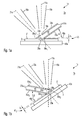
- Figures 1a and 1b schematically show sectional views of a particle optical processing system 1a for two different orientations of the object 3 relative to an axis 11a of an electron beam column 10a.
- the particle optical processing system 1a comprises an electron beam column 10a for generating an electron beam 11a and an ion beam column 20a for generating an ion beam 21a.
- the electron beam column 10a as well as the ion beam column 20a are known from the prior art.
- the electron beam columns 10a and the ion beam column 20a may be constructed as in US 6,855,938 B2 illustrated in Figure 8 and described in the text. The disclosure of US 6,855,938 B2 is entirely incorporated by reference into the present application.
- the electron beam column 10a comprises an electron optics, to focus the electron beam within the vacuum chamber 2a in a focussing region 29a.
- the ion beam column 20a comprises an ion optics, to focus the ion beam 21a in the focussing region 29a.
- Both particle beam columns each comprise a scanning system for deflecting the particle beams in a controlled way, to scan the focussed particle beams across the focussing region 29a.
- processing and inspecting a predefined region of the object 3 arranged in the focussing region is enabled.
- the ion beam column 20a comprises a not illustrated ion source in which liquid gallium is extracted from a reservoir of liquid material and in which the extracted gallium is ionised.
- the object 3 is hold on the object holder 43a such that the surface 3' of the object 3 comprises the focussing region 29a.
- the surface 3' of the object 3 is oriented in a first orientation relative to the beam axis of the electron beam column 10a, wherein a normal of the surface 3' of the object 3 substantially runs parallel to the beam axis of the electron beam column 10a.
- the particle optical processing system 1a comprises a first processing chamber wall 35a 1 being adapted as a cylindrical tube.
- the cylinder may be adapted as an elliptic, circular or a general cylinder.
- the cylindrical tube 35a 1 includes an angle ⁇ with the surface 3' of the object 3, wherein the angle ⁇ is about 35°.
- the angle ⁇ may assume larger or smaller values.
- the angle ⁇ may be selected depending on the application.
- the cylindrical tube 35a 1 exhibits a front face 36a 1 formed by cutting the cylinder with a plane and is arranged opposite to the surface 3' of the object 3 such that a gap 42 1 is formed between the front face 36a 1 of the processing chamber wall 35a 1 and the surface 3' of the object 3.
- the width b of the gap 42 1 amounts to less than 200 ⁇ m, in particular less than 20 ⁇ m.
- the front face 36a 1 abuts on the surface 3' of the object 3 or on the object holder 43, for example via an elastomer lip.
- the front face 36a 1 surrounds the electron beam 11a and the ion beam 21a.
- the first processing chamber wall 35a 1 comprises a connector 37a for supplying process gas to the focussing region 29a.
- process gas is supplied to the space 45 (also referred to as processing chamber) delimited from the vacuum chamber 2a.
- the processing chamber 45 is delimited from the vacuum chamber 2a by the processing chamber wall 35a 1 .
- the first processing chamber wall 35a 1 exhibits an opening 38a for traversal of the electron beam 11a to the focussing region. Further the first processing chamber wall 35a 1 exhibits an opening 39a for traversal of the ion beam 21a to the focussing region 29a. Shapes of both openings 38a and 39a may be adapted in dependence of the orientation of the processing chamber wall 35a 1 relative to the directions of the electron beam 11a or the ion beam 21a.
- the particle optical processing system 1a allows, to direct the electron beam 11a and the ion beam 21a to the focussing region 29a in which the surface 3' of the object 3 is arranged in the presence of a process gas.
- the space 45 in which process gas is present in a relatively high concentration is delimited from other components arranged within the vacuum chamber 2a, in order not to deteriorate a function of these components due to the presence of process gas.
- Electrons emanating from the surface 3' of the object 3 are detected by electron detectors not illustrated in Figures 1a and 1b .
- the electrons emanating from the object may comprise backscatter electrons and secondary electrons.
- the electron detectors may be arranged within the electron beam tube 10a (inline detectors) or may be arranged outside therefrom.
- the electrons emanating from the surface 3' of the object 3 may be released by illuminating the object 3 using the ion beam 21a and/or using the electron beam 11a.
- the detector may also be embedded into the processing chamber wall or may be fixed thereon. Evolving secondary particles (ions, electrons) may be drawn from the processing region towards the detectors by applying an extraction voltage.
- the process gas arriving via the gas connector 37a into the processing chamber 45 and thus in proximity of the focussing region 29a may be activated by the electron beam 11a and/or the ion beam 21a (or an alternative or additional photon beam), to process the object 3 within the focussing region 29a.
- the processing by the activated process gas may comprise ablating material from the surface 3' and/or deposition of material onto the surface 3' of the object 3.
- Figure 1b schematically shows the particle optical processing system 1a in a sectional view for a second orientation of the object 3 relative to the beam axis of the electron beam column 10a.
- a normal of the surface 3' of the object 3 substantially runs parallel to a beam axis of the ion beam column 20a.
- a trench may be cut into the object 3 in a known way by illuminating using the ion beam 21a. Simultaneously a side face of the trench may be inspected using the electron beam 11a via inclined illumination.
- the particle optical processing system 1a comprises, instead of the first processing chamber wall 35a 1 illustrated in Figure 1a , a second processing chamber wall 35a 2 different from the first processing chamber wall 35a 1 .
- the second processing chamber wall 35a 2 is also adapted as a cylindrical tube.
- the second processing chamber wall 35a 2 is adapted, to form a gap 42 2 between the front face 36a 2 of the second processing chamber wall 35a 2 and the surface 3' of the object 3 in the second orientation of the surface 3' of the object 3 relative to the electron beam column 10a, as illustrated in Figure 1b .
- the processing chamber wall 35a 2 includes an angle ⁇ with the surface 3' of the object 3, wherein the angle ⁇ amounts to about 45° in the illustrated example.
- the angle ⁇ is different from the angle ⁇ , indicated in Figure 1a .
- a shape of the front face 36a 2 of the second processing chamber wall 35a 2 differs from a shape of the front face 36a 1 of the first processing chamber wall 35a 1 .
- the width b 2 of the gap 42 2 illustrated in Figure 1b is approximately equal to the width b 1 of the gap 42 1 illustrated in Figure 1a .
- the processing chamber 45 is sealed and delimited from the vacuum chamber 2a in both orientations of the object.
- the second processing chamber wall 35a 2 For traversal of the electron beam 11a from its source to the object the second processing chamber wall 35a 2 exhibits an opening 38a and for traversal of the ion beam 21a the second processing chamber wall 35a 2 exhibits an opening 39a.
- the shapes of these openings are different from the shapes of the openings 38a and 39a of the processing chamber wall 35a 1 .
- the second processing chamber wall 35a 2 comprises a connector 37a for supplying process gas into the space 45.
- this angle may be larger or smaller.
- the angle between the two different orientations may amount to 10°, 20°, 30°, 40°, 50°, 60°g, 75° or may assume a value in-between.
- the processing chamber walls illustrated in Figures 1a and 1b are adapted, such that the first processing chamber wall 35a 1 contacts the object 3 or the object holder 43a in a first orientation of the object and such that the second processing chamber wall 35a 2 contacts the object 3 or the object holder 43a in a second orientation of the object.
- the front face of the corresponding contacting processing chamber wall may for example comprise elastic materials, such as rubber seals.
- the corresponding contacting processing chamber wall may be flush with a corresponding face of the object or the object holder or may contact this face at several contact points.
- FIGs 2a, 2b , and 2c schematically illustrate a further embodiment 1b of a particle optical processing system.
- the particle optical processing system 1a illustrated in Figures 1a and 1b the particle optical processing system 1b comprises an electron beam column 10b for generating an electron beam 11b and focussing the same in the focussing region 29b, as well as an ion beam column 20b for generating an ion beam 21b and focussing the ion beam in the focussing region 29b.
- the object 3 is hold at the object holder 43b, to achieve an orientation of the object 3 in which a normal of the surface 3' of the object 3 is aligned substantially parallel to the beam axis defined by a propagation direction of the electron beam 11b.
- the particle optical processing system 1b further comprises a first wall portion 35b' having an opening 38b for traversal of the electron beam 11b and having an opening 39b for traversal of the ion beam 21b.
- the processing chamber wall of the system 1b further comprises a second wall portion 35b" which is arranged such that a front face 36b of the processing chamber wall 35b faces the surface 3' of the object 3.
- the second wall portion 35b" of the processing chamber wall 35b is pivotable around a pivoting axis 44b relative to the first processing chamber wall 35b' as illustrated in a plan view of the particle optical processing system 1b in Figure 2c .
- Figures 2a and 2b however illustrate a sectional view of the processing system 1b so that the pivoting axis 44b is not visible. Further, in Figures 2a and 2b front and rear end faces of the processing chamber wall formed by the first wall portion 35b' and the second wall portion 35b" are not illustrated.
- Figure 2b schematically illustrates the particle optical processing system 1b in a sectional view in a second orientation of the object 3 relative to the electron beam column 10b.
- This second orientation of the object corresponds to the second orientation of the object which is shown in Figure 1b .
- the second wall portion 35b" is pivoted relative to the first wall portion 35b' around the pivoting axis 44b so that compared to the configuration illustrated in Figure 2a other parts of the second wall portion 35b" overlap with the first wall portion 35b'.
- a gap 42b is formed between the front face 36b and the surface 3' of the object 3, wherein the gap 42b has a substantially unchanged width b compared to the width of the gap 42b in the first orientation illustrated in Figure 2a .
- a demarcation of a processing chamber 45b from the vacuum chamber 2b is enabled, to allow processing the object in the presence of a sufficient concentration of process gas.
- Figure 2c schematically illustrates the particle optical processing system 1b in a plan view according to in Figure 2a indicated directions 2c.
- the first wall portion 35b' comprises the two openings 38b and 39b for traversal of the electron beam 11b and the ion beam 21b, respectively.
- a front end face of the first wall portion 35b' (in the plan view of Figure 2c a lower part of the first wall portion 35b') comprises one or more connectors 37b for supplying process gas (which may comprise a mixture of gases) via a connecting pipe 46.
- a rear end face of the first wall portion 35b' (in the plan view of Figure 2c an upper part of the first wall portion 35b') comprises a connector 41b for discharging the process gas from the focussing region 29b via a discharge pipe 47.
- the second wall portion 35b" is pivotable relative to the first wall portion 35b' around a pivoting axis 44b. Thereby, a discrimination of the processing chamber 45b from the vacuum chamber 2b may be achieved by a suitable relative rotation (pivoting) of the first wall portion 35b' and the second wall portion 35b".
- process gas for activation by the electron beam 11b and/or the ion beam 21b may be provided to the object 3, to cause depositions onto the surface 3' of the object 3 or to cause ablations of material from the surface 3' of the object 3 or to cause conversion of the material.
- processing the object and also inspecting the object may be performed in different orientations of the object relative to the electron beam column 10b or the ion beam column 20b.
- a partial pressure of the process gas within the processing chamber 45b thereby may be a factor of greater than 2, in particular greater than 5, further in particular greater than 20, higher than a partial pressure of the process gas in the vacuum chamber 2b.
- the first wall portion 35b' of the processing chamber wall 35b and the second wall portion 35b" of the processing chamber wall 35b partly assume a shape of a cylinder barrel.
- these wall portions may also assume another shape, as long as a relative displacement of the wall portions relative to each other is enabled that allow demarcation of the processing chamber 45b from the vacuum chamber 2b for different orientations of the object.
- the processing chamber wall 35b may be displaced along directions indicated by the double arrow 49 substantially perpendicular to a plane 48 spanned by the beam axis of the electron beam 11b and the ion beam 21b, to withdraw the processing chamber wall 35b from the focussing region.
- an object at the object holder may for example be replaced or positioned.
- the processing system may be utilized as a pure inspection system.
- the withdrawn processing chamber wall 35b is shifted along a direction defined by the double arrow 49 illustrated in Figure 2c , to partially encompass the focussing region 29b for forming a processing chamber 45b.
- orientations of the object are not restricted to the exemplary orientations illustrated in Figures 2a and 2b , but may have other relative angles, such as 10°, 20°, 30°, 40°, 50°, 60°, or values in-between.
- FIGs 3a and 3b schematically illustrate a processing chamber wall 35c that may be employed in particle optical processing systems.
- Figures 3a and 3b each illustrate front views of the processing chamber wall 35c.
- the processing chamber wall 35c is formed by a first wall portion 35c' and plural second wall portions 35c".
- the wall portions 35c" are pivotable relative to the first wall portion 35c' around a pivoting axis 44c, which is perpendicular to the drawing plane of Figures 3a and 3b .
- Figure 3a illustrates a state of the processing chamber wall 35c, wherein the different wall portions 35c' and 35c" have relative orientations such that overlap regions 48 between abutting wall portions are relatively small. Thereby, a maximal pivoting range of the object holder is defined. During operation the state illustrated in Figure 3a does usually not occur.
- Figure 3b schematically illustrates a state, wherein the wall portions 35c" are pivoted relative to the first wall portion 35c' such that they maximally overlap with the first wall portion 35c' in the overlap regions 48. States of different pivoting of the wall portions relative to each other may be adjusted depending on requirements, to provide a processing chamber 45 in a particle optical processing system.
- FIGs 4a and 4b schematically illustrate in a sectional view analogous to the sectional views of the Figures 1a, 1b , 2a, and 2b a processing system 1d according to a further embodiment.
- the processing system 1d has many components in common with the processing systems 1a and 1b illustrated in Figures 1a and 1b , and in the Figures 2a to 2c , respectively, so that a detailed description of these components may be taken from the description of processing systems 1a and 1b.
- the processing system 1d mainly differs from the afore shown processing systems 1a and 1b by the configuration of the processing chamber wall 35d.
- the processing chamber wall 35d in processing system 1d is formed by a first wall portion 35d', a second wall portion 35d" and a third wall portion 35d"'.
- the first wall portion 35d' comprises an opening 38d for traversal of the electron beam 11d running inside the electron beam column 10d.
- the electron beam 11d is incident in the focussing region 29d onto the object 3.
- the first wall portion 35d' further comprises an opening 39d for traversal of the ion beam 21d running inside the ion beam column 20d.
- the ion beam 21d is incident after traversal through the opening 39d at the focussing region 29d onto the surface 3' of the object 3.
- the second wall portion 35d" comprises a front face 36d of the processing chamber wall 35d which together with the surface 3' of the object 3 forms a gap 42d having a width b of less than 2 mm, in particular less than 200 ⁇ m, further in particular less than 20 ⁇ m.
- the front face 36d may abut at the surface 3' of the object 3 such that no gap is formed.
- the first wall portion 35d' is elastically connected to the second wall portion 35d" via a third wall portion, a bellows 35d"'.
- the bellows 35d"' is a conventional bellows made from metal which is for example used in vacuum technology. Instead of using a bellows also a ring structure comprising elastic material may be employed.
- Figure 4a illustrates a state of the processing system 1d in a first orientation of the object 3 relative to the electron beam column 10d, wherein a normal of the surface 3' of the object is substantially aligned parallel to a propagation direction of the electron beam 11d.
- Figure 4b schematically illustrates the processing system 1d in a state, wherein the object 3 is aligned in a second orientation relative to the electron beam column 10d such that the normal of the surface 3' of the object is substantially aligned parallel to a propagation direction of the ion beam 21d.
- the third wall portion 35d"' in Figure 4b is elastically deformed such that the front face 36d comprised in the second wall portion 35d" together with the surface 3' of the object forms a gap 42d having a width b being substantially unchanged compared to the width in the first orientation.
- Positions of the openings 38d and 39d in Figure 4b are substantially unchanged compared to positions of the openings 38d and 39d in Figure 4a , to allow in both orientations an unhindered traversal of the ion beam and the electron beam to the focussing region 29d.
- a gas supply not illustrated in the Figures 4a and 4b due to the sectional view is adapted, to supply process gas or process gases to the focussing region 29d, so that processing the object may be performed in the presence of process gas. Further, the object may be inspected using the ion beam 21d and/or the electron beam 11d, to determine a progress of the processing.
- FIGs 5a and 5b schematically illustrate in the sectional view analogues to the sectional views of the Figures 1a, 1b , 2a, 2b , 4a, and 4b a processing system 1e according to a still further embodiment.
- the processing system 1e has a number of components in common with the processing systems 1a, 1b or 1d illustrated in Figures 1a and 1b , 2a to 2c , and 4a and 4b , respectively so that a detailed description of these components may be omitted.
- the processing system 1e differs from the afore shown processing systems 1a, 1b, and 1d mainly by the adaptation and configuration of the processing chamber wall 35e and its abutment to the object holder 43e.
- the processing chamber wall 35e in the processing system 1e is formed by a first wall portion 35e', a second wall portion 35e" and a third wall portion 35e"'.
- the first wall portion 35e' comprises an opening 38e for traversal of the electron beam 11e running inside the electron beam column 10e.
- the first wall portion 35e' comprises an opening 39e for traversal of the ion beam 21e running inside the ion beam column 20e.
- the electron beam 11e also the ion beam 21d is incident at the focussing region 29e onto the surface 3' of the object 3.
- the second wall portion 35e" annularly surrounds the object 3 and directly abuts at the object holder 43e.
- the second wall portion 35e" is formed from an elastic material (e.g. elastomer) and forms in the here shown examples a front face 36e of the processing chamber wall 35e which abuts at the object holder 43e.
- no gap is formed between the object 3 and the processing chamber wall.
- the front face 36e of the processing chamber wall 35e abutting with the object holder 43e and thus being flush with the object holder seals a processing chamber 45e from the vacuum chamber 2e, to thus maintain within the processing chamber 45e a partial pressure of a process gas being increased compared to the partial pressure within the vacuum chamber 2e.
- This enables advantageously processing the object by activating the process gas using for example the ion beam, the electron beam or a photon beam.
- the first wall portion 35e' is elastically connected to the second wall portion 35e" via a third wall portion, here a rubber ring (alternatively a bellows, such as made from metal) 35e"'.
- the rubber ring 35e"' is elastically deformable and enables a shape change of the processing chamber wall 35e for different orientation of the object 3 relative to the particle beam columns 10e and 20e.
- Figure 5a illustrates a state of the processing system 1e in a first orientation of the object 3 relative to the electron column 10e, wherein a normal of the surface 3' of the object is substantially aligned parallel to a propagation direction of the electron beam 10d.
- Figure 5b schematically illustrates the processing system 1e in a state, wherein the object 3 is aligned in a second orientation relative to the electron beam column 10e such that the normal of the surface 3' of the object is substantially aligned parallel to a propagation direction of the ion beam 21e.
- processing chamber wall Individual elements or portions of the processing chamber wall illustrated in different embodiments may be combined to provide further embodiments of a processing chamber wall that may be employed in processing systems.
- a gap of substantially same width may be formed in different orientations of the object.
- the processing chamber wall in particular the front face of the processing chamber wall
- the processing chamber wall may abut the object or the object holder, wherein in the latter case the processing chamber wall advantageously surrounds the object without contacting it.
- the processing chamber wall may be formed from one or plural wall portions, wherein the number of the wall portions may be 2, 3, 4, 5, 6 or a higher number.
- a mechanical and/or electronic controller for maintaining a substantially constant width b of the gap 42 between the front face 36 of the processing chamber wall 35 and the surface 3' of the object 3 may be provided.
- the processing chamber wall may comprise a third opening for traversal of a third particle beam and/or a light beam (laser beam).
- a light beam such as a laser beam, may be incident onto the object surface. This may be advantageous for particular applications, for example for surface heating, for reaction activation or for analysis purposes.
Landscapes
- Chemical & Material Sciences (AREA)
- Analytical Chemistry (AREA)
- Engineering & Computer Science (AREA)
- Toxicology (AREA)
- General Chemical & Material Sciences (AREA)
- Chemical Kinetics & Catalysis (AREA)
- Health & Medical Sciences (AREA)
- Materials Engineering (AREA)
- Mechanical Engineering (AREA)
- Metallurgy (AREA)
- Organic Chemistry (AREA)
- Physics & Mathematics (AREA)
- Plasma & Fusion (AREA)
- Analysing Materials By The Use Of Radiation (AREA)
- Welding Or Cutting Using Electron Beams (AREA)
Abstract
Description
- The present application relates to a processing system for processing an object in the presence of a process gas. In particular, the present application relates to a two-beam processing system being adapted at least for generating and focussing a pair of energy beams which energy beams may comprise an electron beam, an ion beam and a photon beam.
- Processing systems are employed in methods for material processing by material deposition from gases, such as CVD (Chemical Vapour Deposition) or by material ablation upon supply of reaction gases. In such processing methods a reaction gas is activated by an electron beam, an ion beam or a photon beam to cause material deposition or to cause material ablation at a region of the object to be processed.
- A conventional inspection and processing system comprising an electron microscopic system and an ion beam system is for example known from
US 6,855,938 B2 . Thereby beam axes of an ion beam column and an electron beam column are arranged enclosing an angle in-between and the system comprises focussing optics for focussing the ion beam and the electron beam at a scanning region. Such a system may for example be utilised for analysis of a previously manufactured semiconductor structure. Upon orthogonal incidence of the ion beam onto the semiconductor structure for example a trench may be cut into the structure and using an electron beam running transverse to the ion beam a sidewall of the trench may be inspected. Thereby for example a layer sequence in the manufactured semiconductor structure may be analyzed for quality control. However, this conventional system does not allow processing the object in the presence of a reaction gas. - A conventional material processing system comprising a gas supply system for material deposition and material ablation is for example known from
US 2006/0284090 A1 . Thereby, the material processing system comprises an electron beam column for generating an electron beam and focussing the electron beam in an object region in which the object to be processed is arrangeable. For supplying a reaction gas to the object region the system further comprises a gas supply system formed by gas nozzles. - Due to increasing miniaturizing of semiconductor components the requirements for processing systems for processing and inspecting such semiconductor structures enhance. In particular higher and higher requirements are imposed on a positioning accuracy of structures within the semiconductor material. Thereby, there is in particular a demand to improve, regarding their accuracy, processing systems operating in the presence of a reaction gas.
- When large amounts of process gas are present within the vacuum chamber of the processing system damage due to the reactive gas may occur (deposition and/or corrosion of the components of the beam optics). Often long evacuation times are required, before the object may be inspected in the absence of the process gas.
- In vie of the above, it is an object of the invention, to provide a processing system for processing an object which at least partly obviates the previously mentioned disadvantages. It is a further object to provide a flexible particle optical processing system which enables processing the object in a variety of ways and simultaneously enables inspecting the object.
- According to an embodiment of the invention, a processing system for processing an object is provided which comprises a first energy beam guiding system having a first beam optics for generating a first energy beam and focussing the same in a focussing region arranged in a vacuum chamber; a second energy beam guiding system having a second beam optics for generating a second energy beam and focussing the same in the focussing region; and at least one processing chamber wall arrangeable within the vacuum chamber such that the processing chamber wall at least partially encompasses the focussing region, wherein the processing chamber wall comprises a front face surrounding, in particular enclosing, the first energy beam and the second energy beam, the front face facing the object; the processing chamber wall further comprises at least one connector for supplying process gas to the focussing region; an opening for traversal of the first energy beam; and an opening for traversal of the second energy beam. Thereby, the first energy beam guiding system is formed by optical components or is adapted as particle beam column and the first energy beam comprises one of a photon beam, an electron beam and an ion beam. Further, the second energy beam guiding system is configured as at least one of an electron beam column and an ion beam column and the second energy beam comprises one of an electron beam and an ion beam.
- Thereby, the processing chamber wall may comprise one connector for supplying process gas to the focussing region or also multiple connectors, potentially at different wall sides or regions for supplying multiple (different) process gases to the focussing region.
- According to an embodiment, the processing system further comprises an object holder for holding the object, wherein the object holder is adapted, to change an orientation of the object relative to a beam direction of the first energy beam from a first orientation to a second orientation different from the first orientation, wherein the processing chamber wall is configured such that both in the first orientation and in the second orientation one of the following holds: a gap is formed between the front face of the processing chamber wall and the object; the front face of the processing chamber wall abuts on the object. In particular, the processing chamber wall delimits a processing chamber containing the object to be processed from a vacuum chamber of the processing system in the first orientation of the object as well as in the second orientation of the object. In the processing chamber a concentration of process gas supplied via the connector may considerably be higher (such as 10 times, 100 times, or 1000 times) than the concentration of the process gas in other parts of the vacuum chamber housing the processing system. The processing chamber wall may comprise one or more processing chamber wall portions.
- According to an exemplary embodiment, the gap formed between the front face of the processing chamber wall and the object may have a width of less than 2 mm, in particular less than 0,5 mm, further in particular less than 200 µm. The width or distance between the front face and the object may differ at different positions of the object.
- According to an embodiment, the front face of the processing chamber wall contacts the object or an object holder holding the object. Thereby, the process gas within the processing chamber delimited by the processing chamber wall may effectively be maintained within the processing chamber by the thus provided sealing effect between the front face and the object or the object holder.
- According to an embodiment, the first energy beam guiding system is adapted as an electron beam column and the first energy beam comprises an electron beam, the second energy beam guiding system is adapted as an ion beam column and the second energy beam comprises an ion beam.
- According to a further exemplary embodiment, a particle optical processing system for processing an object comprises an electron beam column, an ion beam column and a processing chamber wall. The electron beam column is equipped with an electron optics for generating an electron beam and focussing the same in a focussing region arranged within a vacuum chamber. The ion beam column is equipped with an ion optics for generating an ion beam and focussing the same in the focussing region. The processing chamber wall is arrangeable within the vacuum chamber such that the processing chamber wall at least partially encompasses the focussing region. The processing chamber wall of this embodiment may exhibit a front face surrounding, in particular enclosing, the electron beam and the ion beam, the front face facing the object; a connector for supplying process gas to the focussing region; an opening for traversal of the electron beam; and an opening for traversal of the ion beam.
- The focussing region may correspond to at least a part of an object plane of the electron beam column or the ion beam column. The part of the object plane thereby may correspond to a scanning region of the particle beams. Both particle beam columns may comprise a scanning system having deflection elements to guide the corresponding particle beam across the scanning region, for example line by line or column by column.
- The electron optics may comprise a magnetic lens and/or an electrostatic lens, in particular a magnetic lens having an electrostatic immersion lens. The magnetic lens may comprise two pole pieces forming a pole piece gap arranged axially or transversely relative to an axis of the electron beam. The electron optics may further include a beam tube adapted as anode onto which a high positive voltage (for example +8 kV) may be applied during operation. The electron optics may further comprise an electrode onto which a suitable potential (for example 0 V to 50 V) may be applied, wherein the electrode (also called termination electrode) is arranged between the beam tube adapted as anode and the object to be processed of inspected. Thus, the electron beam column enables to generate electrons, to accelerate the electrons to a high kinetic energy and to decelerate the electrons to a relatively low kinetic energy before incidence in the focussing region at the surface of the object.
- According to an embodiment, the processing system further comprises at least one electron detector for detecting electrons emanating from the object. The electrons emanating from the object may comprise backscatter electrons and/or secondary electrons. Using a scanning system and the electron detector an electron microscopic image of the object to be examined may be acquired.
- The ion beam column may comprise electrostatic lenses and magnetic lenses. Further, the ion beam column comprises an ion source including a reservoir of solid material or a reservoir of liquid material and/or including a gas supply. From the reservoir of solid material or the reservoir of liquid material materials, such as liquid gallium, may be extracted by thermal activation and using an extractor electrode which generates an electric field. Via the gas supply gaseous elements or molecules may be supplied. After ionising the particles extracted from the reservoir of solid material or the reservoir of liquid material or the particles supplied via the gas supply the particles are accelerated by a suitable electric field to form the ion beam.
- A beam axis of the electron beam column and a beam axis of the ion beam column may in particular include an angle which is greater than 10°. This angle may however also be smaller than 10°, as long as the electron beam column and the ion beam column are adapted, to focus the electron beam and the ion beam in the same focussing region.
- Together with a surface of the object to be processed the processing chamber wall may delimit a processing chamber within the vacuum chamber, wherein the processing chamber may contain process gas in an enhanced concentration when compared to the concentration within the vacuum chamber. Thereby, the focussing region is situated within the such delimited processing chamber.
- The processing chamber wall may exhibit different shapes. The processing chamber wall may for example comprise a bowl shape, a shape of a cylindrical shell or a dome shape. The processing chamber wall may comprise elastic, flexible materials, wherein the processing chamber wall may be integrally formed or may be manufactured from several separate elements. The front face of the processing chamber wall facing the object may annularly enclose the electron beam and the ion beam, wherein an annular shape is not necessarily a circular shape, but may for example also comprise a rectangular shape, a quadratic shape, a ellipse shape and the like.
- The connector provided in the processing chamber wall for supplying process gas to the focussing region enables to provide process gas in the vicinity of the focussing region. Using the electron beam and/or the ion beam and/or the photon beam the process gas may be activated, to thus process the object. For traversal of the electron beam and for traversal the ion beam from their respective sources towards the focussing region corresponding openings are provided in the processing chamber wall.
- Plural openings for beam traversal may be provided, for example for different orientations or lateral positions of the object.
- Thus the particle optical processing system allows in an advantageous way processing an object in the presence of a process gas by activating the process gas by the electron beam and/or the ion beam and/or the photon beam and the particle optical processing system allows also inspecting the object using the electron beam and/or the ion beam and/or the photon beam.
- According to an embodiment, the front face of the processing chamber wall substantially extends in a plane. In cases, where the front face is not entirely located in a plane, but the front face exhibits deviations from a plane, the plane in which the front face is substantially located may for example be defined by a fitting plan representing a good approximation of a shape of the front face of the processing chamber wall. Thus, not all portions of the front face need to be located in the fitting plane, but may be located outside the fitting plane. A major portion of the front face may however be considered, to define a fitting plane having small deviations from the front face of the processing chamber wall. During operation of the processing system the fitting plane of the front face of the processing chamber wall may substantially extend parallel to a surface of the object to be processed.
- The processing chamber wall partially extends transverse to the fitting plane. By arranging the processing chamber wall such that it partially extends transverse to the plane a processing chamber is formed comprising a space located above the focussing region. In this processing chamber a supplied process gas is delimited from the vacuum chamber of the processing system by the processing chamber wall and thus may be maintained at a relatively high concentration compared to its concentration within the vacuum chamber.
- According to an embodiment, the processing chamber wall further comprises a connector for discharging gas from the focussing region. The process gas thereby may be discharged from the focussing region and thus from the processing chamber to terminate processing the object using the process gas or to remove process gas that has reacted with the object or to remove purge gas.
- According to an embodiment, the processing chamber wall is adapted, to be arranged facing the object such that the gap between the object and the front face has a width of less than 2 mm, in particular less than 2,5 mm, further in particular less than 200 µm, still further in particular less than 20 µm.
- According to another embodiment, the processing chamber wall or the front face of the processing chamber wall may contact the object or may contact an object holder holding the object. Thereby, the processing chamber wall is set without a gap, and thus in a flush way, on the object. This may be achieved by a mechanical spring mechanism or an elastic material between object or object holder and processing chamber wall. In other embodiments the processing chamber wall and in particular the front face of the processing chamber wall may contact the object or the object holder at plural contact points, such as three or more contact points, and in other portions of the front face of the processing chamber wall a gap is formed between the object and the processing chamber wall.
- When the object and the processing chamber wall contact each other or when a gap having a small width is provided in-between a processing chamber may effectively be delimited from the vacuum chamber to avoid that the vacuum chamber and components of the processing system situated therein are exposed to process gas to an excessive degree. Thus, damage of these components of the processing system may be reduced and a reliable operation of the processing system may be ensured.
- According to an embodiment, the at least one processing chamber wall comprises a first processing chamber wall and a second processing chamber wall which are alternatively arrangeable within the vacuum chamber, wherein the first processing chamber wall is adapted, to form the gap in the first orientation of the object, and wherein the second processing chamber wall is adapted, to form the gap in the second orientation of the object. This embodiment may in particular be advantageously employed in cases, where only two orientations of the object must be set for processing and inspecting the object. Thereby, the first processing chamber wall and the second processing chamber wall may be constructed in a particular simple and cost effective way and may be alternatively arranged for different orientations of the object, to at least partially encompass the focussing region and thus to form the processing chamber. For example, the first processing chamber wall and the second processing chamber wall may substantially be orthogonally displaceable relative to one of the particle beam directions for removal and/or insertion.
- According to an embodiment, the front face is adapted to surround the object in the first orientation and in the second orientation and the front face and the object holder are adapted, to contact each other in the first orientation and the second orientation. Thus, the front face of the processing chamber wall is flush with the object holder, to effectively form a gas sealing.
- According to an embodiment, the at least one processing chamber wall comprises a first processing chamber wall and a second processing chamber wall which are alternatively arrangeable within the vacuum chamber, wherein the front face of the first processing chamber wall is adapted, to contact the object holder in the first orientation of the object, and wherein the front face of the second processing chamber wall is adapted, to contact the object holder in the second orientation of the object.
- According to an embodiment, the processing chamber wall comprises at least two wall portions being displaceable relative to each other of which a first wall portion comprises the opening for the first energy beam and the opening for the second energy beam and of which a second wall portion provides at least a part of the front face facing the object. The first wall portion of the processing chamber wall thereby may be fixedly, for example directly or indirectly, connected to the electron beam column and/or the ion beam column, to ensure that a position of the opening for traversal of the ion beam and a position of the opening for traversal of the electron beam is substantially unchanged for different orientations of the object. The gap between the object or the object holder and the front face of the processing chamber wall or a gap free sealing face may thereby be partially formed by the second processing wall portion and the object.
- According to an embodiment, the first wall portion and the second wall portion are pivotable relative to each other around a pivoting axis. Thereby it is enabled, to form the gap between the object or the object holder and the front face of the processing chamber wall for different orientations of the object with substantially unchanged width. Thus, a processing chamber is formed for different orientations of the object.
- According to an embodiment, the first wall portion and the second wall portion are partially overlapping arranged side by side. An amount of overlap of the first wall portion and the second wall portion may be different for different orientations of the object. In the overlap region between the first wall portion and the second wall portion a sealing element may be arranged, to provide an effective sealing for process gas, such as for example via a gap free abutment in overlap regions. In particular a region of the first wall portion which does not overlap with the second wall portion in any of the orientations of the object to be set may be equipped with the connector for supplying the process gas as well as with a connector for discharging the process gas.
- According to a further embodiment, the first wall portion and the second wall portion are elastically connected to each other by a third wall portion. The third wall portion may for example comprise an elastic, flexible material or may for example comprise a bellows, to enable a necessary shape change of the processing chamber wall for different orientations of the object. Also, the third wall portion may comprise elements that are telescopically displaceable into each other.
- Embodiments of the present invention are now described referring to the accompanying drawings.
- Figures 1a and 1b
- schematically show an embodiment of a particle optical processing system;
- Figures 2a, 2b and 2c
- schematically show a further embodiment of a particle optical processing system;
- Figures 3a and 3b
- schematically show an embodiment of a processing chamber wall which may be employed in a particle optical processing system shown in
Figures 1 and2 ; - Figures 4a and 4b
- schematically show a further embodiment of a particle optical processing system; and
- Figures 5a and 5b
- schematically show a still further embodiment of a particle optical processing system.
-
Figures 1a and 1b schematically show sectional views of a particleoptical processing system 1a for two different orientations of theobject 3 relative to anaxis 11a of anelectron beam column 10a. - The particle
optical processing system 1a comprises anelectron beam column 10a for generating anelectron beam 11a and anion beam column 20a for generating anion beam 21a. Theelectron beam column 10a as well as theion beam column 20a are known from the prior art. For example, theelectron beam columns 10a and theion beam column 20a may be constructed as inUS 6,855,938 B2 illustrated in Figure 8 and described in the text. The disclosure ofUS 6,855,938 B2 is entirely incorporated by reference into the present application. Theelectron beam column 10a comprises an electron optics, to focus the electron beam within thevacuum chamber 2a in a focussingregion 29a. Similarly theion beam column 20a comprises an ion optics, to focus theion beam 21a in the focussingregion 29a. - Both particle beam columns each comprise a scanning system for deflecting the particle beams in a controlled way, to scan the focussed particle beams across the focussing
region 29a. Thus, processing and inspecting a predefined region of theobject 3 arranged in the focussing region is enabled. - In the example illustrated here the
ion beam column 20a comprises a not illustrated ion source in which liquid gallium is extracted from a reservoir of liquid material and in which the extracted gallium is ionised. Theobject 3 is hold on theobject holder 43a such that the surface 3' of theobject 3 comprises the focussingregion 29a. InFigure 1a the surface 3' of theobject 3 is oriented in a first orientation relative to the beam axis of theelectron beam column 10a, wherein a normal of the surface 3' of theobject 3 substantially runs parallel to the beam axis of theelectron beam column 10a. In this orientation of the surface 3' of theobject 3 the particleoptical processing system 1a comprises a first processing chamber wall 35a1 being adapted as a cylindrical tube. The cylinder may be adapted as an elliptic, circular or a general cylinder. In the sectional view ofFigure 1a the cylindrical tube 35a1 includes an angle α with the surface 3' of theobject 3, wherein the angle α is about 35°. In other embodiments, the angle α may assume larger or smaller values. In particular, the angle α may be selected depending on the application. - The cylindrical tube 35a1 exhibits a
front face 36a1 formed by cutting the cylinder with a plane and is arranged opposite to the surface 3' of theobject 3 such that a gap 421 is formed between thefront face 36a1 of the processing chamber wall 35a1 and the surface 3' of theobject 3. The width b of the gap 421 amounts to less than 200 µm, in particular less than 20 µm. In other embodiments thefront face 36a1 abuts on the surface 3' of theobject 3 or on the object holder 43, for example via an elastomer lip. Thefront face 36a1 surrounds theelectron beam 11a and theion beam 21a. - The first processing chamber wall 35a1 comprises a
connector 37a for supplying process gas to the focussingregion 29a. In particular, process gas is supplied to the space 45 (also referred to as processing chamber) delimited from thevacuum chamber 2a. Theprocessing chamber 45 is delimited from thevacuum chamber 2a by the processing chamber wall 35a1. - The first processing chamber wall 35a1 exhibits an
opening 38a for traversal of theelectron beam 11a to the focussing region. Further the first processing chamber wall 35a1 exhibits anopening 39a for traversal of theion beam 21a to the focussingregion 29a. Shapes of bothopenings electron beam 11a or theion beam 21a. Thus, the particleoptical processing system 1a allows, to direct theelectron beam 11a and theion beam 21a to the focussingregion 29a in which the surface 3' of theobject 3 is arranged in the presence of a process gas. At the same time thespace 45 in which process gas is present in a relatively high concentration is delimited from other components arranged within thevacuum chamber 2a, in order not to deteriorate a function of these components due to the presence of process gas. - Electrons emanating from the surface 3' of the
object 3 are detected by electron detectors not illustrated inFigures 1a and 1b . The electrons emanating from the object may comprise backscatter electrons and secondary electrons. The electron detectors may be arranged within theelectron beam tube 10a (inline detectors) or may be arranged outside therefrom. The electrons emanating from the surface 3' of theobject 3 may be released by illuminating theobject 3 using theion beam 21a and/or using theelectron beam 11a. Alternatively, the detector may also be embedded into the processing chamber wall or may be fixed thereon. Evolving secondary particles (ions, electrons) may be drawn from the processing region towards the detectors by applying an extraction voltage. - By scanning the one or more focussed particle beams across the focussing region and detecting the released electrons an electron microscopy image of the region of the
object 3 arranged in the focussingregion 29a is obtained. - The process gas arriving via the
gas connector 37a into theprocessing chamber 45 and thus in proximity of the focussingregion 29a may be activated by theelectron beam 11a and/or theion beam 21a (or an alternative or additional photon beam), to process theobject 3 within the focussingregion 29a. The processing by the activated process gas may comprise ablating material from the surface 3' and/or deposition of material onto the surface 3' of theobject 3. By supplying inert gas a protection of the object from reactive process gas may be achieved or a thermal treatment of the object may be performed. -
Figure 1b schematically shows the particleoptical processing system 1a in a sectional view for a second orientation of theobject 3 relative to the beam axis of theelectron beam column 10a. For this second orientation a normal of the surface 3' of theobject 3 substantially runs parallel to a beam axis of theion beam column 20a. In this orientation a trench may be cut into theobject 3 in a known way by illuminating using theion beam 21a. Simultaneously a side face of the trench may be inspected using theelectron beam 11a via inclined illumination. In the inFigure 1b illustrated orientation of the object relative to theelectron beam column 10a the particleoptical processing system 1a comprises, instead of the first processing chamber wall 35a1 illustrated inFigure 1a , a second processing chamber wall 35a2 different from the first processing chamber wall 35a1. The second processing chamber wall 35a2 is also adapted as a cylindrical tube. The second processing chamber wall 35a2 is adapted, to form a gap 422 between thefront face 36a2 of the second processing chamber wall 35a2 and the surface 3' of theobject 3 in the second orientation of the surface 3' of theobject 3 relative to theelectron beam column 10a, as illustrated inFigure 1b . The processing chamber wall 35a2 includes an angle β with the surface 3' of theobject 3, wherein the angle β amounts to about 45° in the illustrated example. In particular, the angle β is different from the angle α, indicated inFigure 1a . Thus, a shape of thefront face 36a2 of the second processing chamber wall 35a2 differs from a shape of thefront face 36a1 of the first processing chamber wall 35a1. The width b2 of the gap 422 illustrated inFigure 1b is approximately equal to the width b1 of the gap 421 illustrated inFigure 1a . Thus, theprocessing chamber 45 is sealed and delimited from thevacuum chamber 2a in both orientations of the object. - For traversal of the
electron beam 11a from its source to the object the second processing chamber wall 35a2 exhibits anopening 38a and for traversal of theion beam 21a the second processing chamber wall 35a2 exhibits anopening 39a. The shapes of these openings are different from the shapes of theopenings connector 37a for supplying process gas into thespace 45. Thus it is enabled, to inspect and to process theobject 3 also in this second orientation, in analogy as described with reference toFigure 1a . - The two orientations of the
object 3 illustrated inFigures 1a and 1b differ by an angle of about 45°. - Depending on an application this angle may be larger or smaller. For example the angle between the two different orientations may amount to 10°, 20°, 30°, 40°, 50°, 60°g, 75° or may assume a value in-between.
- In other embodiments, the processing chamber walls illustrated in
Figures 1a and 1b are adapted, such that the first processing chamber wall 35a1 contacts theobject 3 or theobject holder 43a in a first orientation of the object and such that the second processing chamber wall 35a2 contacts theobject 3 or theobject holder 43a in a second orientation of the object. Thereby, the front face of the corresponding contacting processing chamber wall may for example comprise elastic materials, such as rubber seals. Thereby, the corresponding contacting processing chamber wall may be flush with a corresponding face of the object or the object holder or may contact this face at several contact points. -
Figures 2a, 2b , and2c schematically illustrate afurther embodiment 1b of a particle optical processing system. As the particleoptical processing system 1a illustrated inFigures 1a and 1b the particleoptical processing system 1b comprises anelectron beam column 10b for generating anelectron beam 11b and focussing the same in the focussingregion 29b, as well as anion beam column 20b for generating anion beam 21b and focussing the ion beam in the focussingregion 29b. - The
object 3 is hold at theobject holder 43b, to achieve an orientation of theobject 3 in which a normal of the surface 3' of theobject 3 is aligned substantially parallel to the beam axis defined by a propagation direction of theelectron beam 11b. The particleoptical processing system 1b further comprises afirst wall portion 35b' having anopening 38b for traversal of theelectron beam 11b and having anopening 39b for traversal of theion beam 21b. The processing chamber wall of thesystem 1b further comprises asecond wall portion 35b" which is arranged such that afront face 36b of theprocessing chamber wall 35b faces the surface 3' of theobject 3. Between thefront face 36b and the surface 3' of the object 3 agap 42b having a width b of smaller than 2 mm, in particular smaller than 200 µm, further in particular smaller than 20 µm, is formed. It is also possible that this width substantially vanishes so that no gap is formed between the front face and the surface of the object but such that the front face and the surface are flush with each other or comprise plural contact points. Thesecond wall portion 35b" of theprocessing chamber wall 35b is pivotable around a pivotingaxis 44b relative to the firstprocessing chamber wall 35b' as illustrated in a plan view of the particleoptical processing system 1b inFigure 2c .Figures 2a and 2b however illustrate a sectional view of theprocessing system 1b so that the pivotingaxis 44b is not visible. Further, inFigures 2a and 2b front and rear end faces of the processing chamber wall formed by thefirst wall portion 35b' and thesecond wall portion 35b" are not illustrated. -
Figure 2b schematically illustrates the particleoptical processing system 1b in a sectional view in a second orientation of theobject 3 relative to theelectron beam column 10b. This second orientation of the object corresponds to the second orientation of the object which is shown inFigure 1b . Compared to theprocessing chamber wall 35b illustrated inFigure 2a thesecond wall portion 35b" is pivoted relative to thefirst wall portion 35b' around the pivotingaxis 44b so that compared to the configuration illustrated inFigure 2a other parts of thesecond wall portion 35b" overlap with thefirst wall portion 35b'. At the same time however, in spite of the changed orientation of theobject 3 relative to theelectron beam column 10b, agap 42b is formed between thefront face 36b and the surface 3' of theobject 3, wherein thegap 42b has a substantially unchanged width b compared to the width of thegap 42b in the first orientation illustrated inFigure 2a . Thus, in the exemplarily illustrated orientations shown inFigures 2a and 2b which differ by an angle of about 45° a demarcation of aprocessing chamber 45b from thevacuum chamber 2b is enabled, to allow processing the object in the presence of a sufficient concentration of process gas. -
Figure 2c schematically illustrates the particleoptical processing system 1b in a plan view according to inFigure 2a indicateddirections 2c. Thefirst wall portion 35b' comprises the twoopenings electron beam 11b and theion beam 21b, respectively. A front end face of thefirst wall portion 35b' (in the plan view ofFigure 2c a lower part of thefirst wall portion 35b') comprises one ormore connectors 37b for supplying process gas (which may comprise a mixture of gases) via a connectingpipe 46. A rear end face of thefirst wall portion 35b' (in the plan view ofFigure 2c an upper part of thefirst wall portion 35b') comprises aconnector 41b for discharging the process gas from the focussingregion 29b via adischarge pipe 47. - The
second wall portion 35b" is pivotable relative to thefirst wall portion 35b' around a pivotingaxis 44b. Thereby, a discrimination of theprocessing chamber 45b from thevacuum chamber 2b may be achieved by a suitable relative rotation (pivoting) of thefirst wall portion 35b' and thesecond wall portion 35b". Thus, process gas for activation by theelectron beam 11b and/or theion beam 21b may be provided to theobject 3, to cause depositions onto the surface 3' of theobject 3 or to cause ablations of material from the surface 3' of theobject 3 or to cause conversion of the material. Due to their substantially fixed positions of theopenings electron beam 11b and theion beam 21b, respectively, such processing the object and also inspecting the object may be performed in different orientations of the object relative to theelectron beam column 10b or theion beam column 20b. - A partial pressure of the process gas within the
processing chamber 45b thereby may be a factor of greater than 2, in particular greater than 5, further in particular greater than 20, higher than a partial pressure of the process gas in thevacuum chamber 2b. - In the
Figures 2a, 2b , and2c of the embodiment thefirst wall portion 35b' of theprocessing chamber wall 35b and thesecond wall portion 35b" of theprocessing chamber wall 35b partly assume a shape of a cylinder barrel. However, these wall portions may also assume another shape, as long as a relative displacement of the wall portions relative to each other is enabled that allow demarcation of theprocessing chamber 45b from thevacuum chamber 2b for different orientations of the object. - The
processing chamber wall 35b may be displaced along directions indicated by thedouble arrow 49 substantially perpendicular to aplane 48 spanned by the beam axis of theelectron beam 11b and theion beam 21b, to withdraw theprocessing chamber wall 35b from the focussing region. In such a withdrawn state an object at the object holder may for example be replaced or positioned. Further, in this state the processing system may be utilized as a pure inspection system. When an object in the presence of a process gas should be processed by activating the process gas, the withdrawnprocessing chamber wall 35b is shifted along a direction defined by thedouble arrow 49 illustrated inFigure 2c , to partially encompass the focussingregion 29b for forming aprocessing chamber 45b. - The orientations of the object are not restricted to the exemplary orientations illustrated in
Figures 2a and 2b , but may have other relative angles, such as 10°, 20°, 30°, 40°, 50°, 60°, or values in-between. -
Figures 3a and 3b schematically illustrate aprocessing chamber wall 35c that may be employed in particle optical processing systems.Figures 3a and 3b each illustrate front views of theprocessing chamber wall 35c. Theprocessing chamber wall 35c is formed by afirst wall portion 35c' and pluralsecond wall portions 35c". Thewall portions 35c" are pivotable relative to thefirst wall portion 35c' around a pivotingaxis 44c, which is perpendicular to the drawing plane ofFigures 3a and 3b . -
Figure 3a illustrates a state of theprocessing chamber wall 35c, wherein thedifferent wall portions 35c' and 35c" have relative orientations such thatoverlap regions 48 between abutting wall portions are relatively small. Thereby, a maximal pivoting range of the object holder is defined. During operation the state illustrated inFigure 3a does usually not occur. -
Figure 3b schematically illustrates a state, wherein thewall portions 35c" are pivoted relative to thefirst wall portion 35c' such that they maximally overlap with thefirst wall portion 35c' in theoverlap regions 48. States of different pivoting of the wall portions relative to each other may be adjusted depending on requirements, to provide aprocessing chamber 45 in a particle optical processing system. -
Figures 4a and 4b schematically illustrate in a sectional view analogous to the sectional views of theFigures 1a, 1b ,2a, and 2b aprocessing system 1d according to a further embodiment. Theprocessing system 1d has many components in common with theprocessing systems Figures 1a and 1b , and in theFigures 2a to 2c , respectively, so that a detailed description of these components may be taken from the description ofprocessing systems - The
processing system 1d mainly differs from the afore shown processingsystems processing chamber wall 35d. Theprocessing chamber wall 35d inprocessing system 1d is formed by afirst wall portion 35d', asecond wall portion 35d" and athird wall portion 35d"'. Thereby, thefirst wall portion 35d' comprises anopening 38d for traversal of theelectron beam 11d running inside theelectron beam column 10d. Theelectron beam 11d is incident in the focussingregion 29d onto theobject 3. Thefirst wall portion 35d' further comprises anopening 39d for traversal of theion beam 21d running inside theion beam column 20d. Also theion beam 21d is incident after traversal through theopening 39d at the focussingregion 29d onto the surface 3' of theobject 3. - In the illustrated example the
second wall portion 35d" comprises afront face 36d of theprocessing chamber wall 35d which together with the surface 3' of theobject 3 forms agap 42d having a width b of less than 2 mm, in particular less than 200 µm, further in particular less than 20 µm. In other embodiments thefront face 36d may abut at the surface 3' of theobject 3 such that no gap is formed. Thefirst wall portion 35d' is elastically connected to thesecond wall portion 35d" via a third wall portion, abellows 35d"'. For example thebellows 35d"' is a conventional bellows made from metal which is for example used in vacuum technology. Instead of using a bellows also a ring structure comprising elastic material may be employed. -
Figure 4a illustrates a state of theprocessing system 1d in a first orientation of theobject 3 relative to theelectron beam column 10d, wherein a normal of the surface 3' of the object is substantially aligned parallel to a propagation direction of theelectron beam 11d. - In contrast,
Figure 4b schematically illustrates theprocessing system 1d in a state, wherein theobject 3 is aligned in a second orientation relative to theelectron beam column 10d such that the normal of the surface 3' of the object is substantially aligned parallel to a propagation direction of theion beam 21d. Compared to the configuration of thethird wall portion 35d"' illustrated inFigure 4a thethird wall portion 35d"' inFigure 4b is elastically deformed such that thefront face 36d comprised in thesecond wall portion 35d" together with the surface 3' of the object forms agap 42d having a width b being substantially unchanged compared to the width in the first orientation. - Positions of the
openings Figure 4b are substantially unchanged compared to positions of theopenings Figure 4a , to allow in both orientations an unhindered traversal of the ion beam and the electron beam to the focussingregion 29d. A gas supply not illustrated in theFigures 4a and 4b due to the sectional view is adapted, to supply process gas or process gases to the focussingregion 29d, so that processing the object may be performed in the presence of process gas. Further, the object may be inspected using theion beam 21d and/or theelectron beam 11d, to determine a progress of the processing. -
Figures 5a and 5b schematically illustrate in the sectional view analogues to the sectional views of theFigures 1a, 1b ,2a, 2b ,4a, and 4b aprocessing system 1e according to a still further embodiment. Theprocessing system 1e has a number of components in common with theprocessing systems Figures 1a and 1b ,2a to 2c , and4a and 4b , respectively so that a detailed description of these components may be omitted. - The
processing system 1e differs from the afore shown processingsystems processing chamber wall 35e and its abutment to theobject holder 43e. Theprocessing chamber wall 35e in theprocessing system 1e is formed by afirst wall portion 35e', asecond wall portion 35e" and athird wall portion 35e"'. Thereby, thefirst wall portion 35e' comprises anopening 38e for traversal of theelectron beam 11e running inside theelectron beam column 10e. Further, thefirst wall portion 35e' comprises anopening 39e for traversal of theion beam 21e running inside theion beam column 20e. As theelectron beam 11e also theion beam 21d is incident at the focussingregion 29e onto the surface 3' of theobject 3. - The
second wall portion 35e" annularly surrounds theobject 3 and directly abuts at theobject holder 43e. Thesecond wall portion 35e" is formed from an elastic material (e.g. elastomer) and forms in the here shown examples afront face 36e of theprocessing chamber wall 35e which abuts at theobject holder 43e. Thus, in this embodiment no gap is formed between theobject 3 and the processing chamber wall. Instead, thefront face 36e of theprocessing chamber wall 35e abutting with theobject holder 43e and thus being flush with the object holder seals aprocessing chamber 45e from thevacuum chamber 2e, to thus maintain within theprocessing chamber 45e a partial pressure of a process gas being increased compared to the partial pressure within thevacuum chamber 2e. This enables advantageously processing the object by activating the process gas using for example the ion beam, the electron beam or a photon beam. - Similar as in the
processing chamber wall 35d illustrated inFigures 4a and 4b thefirst wall portion 35e' is elastically connected to thesecond wall portion 35e" via a third wall portion, here a rubber ring (alternatively a bellows, such as made from metal) 35e"'. Therubber ring 35e"' is elastically deformable and enables a shape change of theprocessing chamber wall 35e for different orientation of theobject 3 relative to theparticle beam columns rubber ring 35e"' situated in the sectional view ofFigure 4a at the right hand side relative to the particle beam axis is arranged in an elongated conformation while a part of therubber ring 35e"' situated on the left hand side is adapted in a compressed conformation comprising a bulge. These conformations occur in a reversed way inFigure 5b showing a state of an orientation of the object which is different from the orientation illustrated inFigure 5a . -
Figure 5a illustrates a state of theprocessing system 1e in a first orientation of theobject 3 relative to theelectron column 10e, wherein a normal of the surface 3' of the object is substantially aligned parallel to a propagation direction of theelectron beam 10d. - In contrast,
Figure 5b schematically illustrates theprocessing system 1e in a state, wherein theobject 3 is aligned in a second orientation relative to theelectron beam column 10e such that the normal of the surface 3' of the object is substantially aligned parallel to a propagation direction of theion beam 21e. - Individual elements or portions of the processing chamber wall illustrated in different embodiments may be combined to provide further embodiments of a processing chamber wall that may be employed in processing systems.
- For example between the processing chamber wall (in particular between the front face of the processing chamber wall) and the object a gap of substantially same width may be formed in different orientations of the object. Alternatively, the processing chamber wall (in particular the front face of the processing chamber wall) may abut the object or the object holder, wherein in the latter case the processing chamber wall advantageously surrounds the object without contacting it. Thus, a particular effective sealing between the processing chamber and the vacuum chamber may be achieved and at the same time damage of the object may be prohibited.
- The processing chamber wall may be formed from one or plural wall portions, wherein the number of the wall portions may be 2, 3, 4, 5, 6 or a higher number. A mechanical and/or electronic controller for maintaining a substantially constant width b of the gap 42 between the front face 36 of the processing chamber wall 35 and the surface 3' of the
object 3 may be provided. Further, the processing chamber wall may comprise a third opening for traversal of a third particle beam and/or a light beam (laser beam). Thereby, beside particle beams also a light beam, such as a laser beam, may be incident onto the object surface. This may be advantageous for particular applications, for example for surface heating, for reaction activation or for analysis purposes. - While the invention has been described also with respect to certain specific embodiments thereof, it is evident that many alternatives, modifications and variations will be apparent to those skilled in the art. Accordingly, the preferred embodiments of the invention set forth herein are intended to be illustrative and not limiting in any way. Various changes may be made without departing from the spirit and scope of the present invention as given by the following claims and equivalents thereof.
Claims (14)
- A processing system for processing an object, the processing system comprising:a first energy beam guiding system having first optics configured for generating a first energy beam and focusing the first energy beam in a focusing region located in a vacuum chamber;a second energy beam guiding system having second optics configured for generating a second energy beam and focusing the second energy beam in the focusing region;at least one processing chamber wall which is arrangeable within the vacuum chamber such that the processing chamber wall at least partially encompasses the focusing region, wherein the processing chamber wall comprises a ring-shaped front face substantially disposed in a plane, wherein the front face surrounds a beam path of the first energy beam and a beam path of the second energy beam; wherein the processing chamber wall has at least one connector for supplying a process gas to the focusing region; wherein a first opening traversed by the beam path of the first energy beam is formed in the processing chamber wall; wherein a second opening traversed by the beam path of the second energy beam is formed in the processing chamber wall, and wherein the second opening is spaced apart from the first opening.
- The processing system according to claim 1, further comprising an object holder for holding the object,
wherein the object holder is adapted to change an orientation of the object relative to the beam path of the first energy beam from a first orientation to a second orientation different from the first orientation,
wherein the processing chamber wall is configured such that the front face of the processing chamber wall is located proximate to one of the object and the object holder in both the first orientation and the second orientation. - The processing system according to claim 2, wherein a gap is formed between the front face of the processing chamber wall and the at least one of the object and the object holder in both the first orientation and the second orientation.
- The processing system according to claim 3, wherein the gap has a width of less than 200 µm.
- The processing system according to claim 2, wherein the front face of the processing chamber wall abuts the at least one of the object and the object holder in both the first orientation and the second orientation.
- The processing system according to one of claims 1 to 5, wherein at least one of the first energy beam and the second energy beam is one of an electron beam and an ion beam.
- The processing system according to one of claims 1 to 6, wherein the first energy beam guiding system comprises an electron beam column, and wherein the second energy beam guiding system comprises an ion beam column.
- The processing system according to one of claims 1 to 7, wherein the processing chamber wall has a portion extending in a direction transverse to the plane.
- The processing system according to one of claims 1 to 8, wherein the processing chamber wall further comprises a connector for discharging the process gas from the focusing region.
- The processing system according to claim 7, comprising a first processing chamber wall and a second processing chamber wall which are alternatively arrangeable within the vacuum chamber, wherein the first processing chamber wall is adapted such that the front face of the first processing chamber wall is proximate to the one of the object and the object holder in the first orientation, and wherein the second processing chamber wall is adapted such that the front face of the second processing chamber wall is proximate to the one of the object and the object holder in the second orientation.
- The processing system according to one of claims 1 to 10, wherein the processing chamber wall comprises a first wall portion and a second wall portion being displaceable relative to each other, wherein the first wall portion provides the first opening and the second opening, and wherein the second wall portion comprises at least a portion of the front face.
- The processing system according to claim 11, wherein the first wall portion and the second wall portion are pivotable relative to each other about an axis.
- The processing system according to claim 11 or 12,
wherein the first wall portion and the second wall portion are arranged side by side such that portions of surfaces of the first and second wall portions overlap. - The processing system according to claim 11 or 12,
wherein the first wall portion and the second wall portion are elastically connected to each other by a third wall portion.
Applications Claiming Priority (1)
| Application Number | Priority Date | Filing Date | Title |
|---|---|---|---|
| DE200810009640 DE102008009640A1 (en) | 2008-02-18 | 2008-02-18 | processing system |
Publications (3)
| Publication Number | Publication Date |
|---|---|
| EP2091066A2 true EP2091066A2 (en) | 2009-08-19 |
| EP2091066A3 EP2091066A3 (en) | 2010-04-28 |
| EP2091066B1 EP2091066B1 (en) | 2011-07-13 |
Family
ID=40551578
Family Applications (1)
| Application Number | Title | Priority Date | Filing Date |
|---|---|---|---|
| EP20090002286 Active EP2091066B1 (en) | 2008-02-18 | 2009-02-18 | Processing system |
Country Status (3)
| Country | Link |
|---|---|
| US (3) | US20100024730A1 (en) |
| EP (1) | EP2091066B1 (en) |
| DE (1) | DE102008009640A1 (en) |
Cited By (1)
| Publication number | Priority date | Publication date | Assignee | Title |
|---|---|---|---|---|
| EP2515321A1 (en) | 2011-04-21 | 2012-10-24 | Carl Zeiss NTS GmbH | Charged particle beam processing system with pivoting annular gas delivery system |
Families Citing this family (6)
| Publication number | Priority date | Publication date | Assignee | Title |
|---|---|---|---|---|
| US10016196B2 (en) * | 2008-09-11 | 2018-07-10 | Covidien Lp | Tapered looped suture |
| DE102010024625A1 (en) * | 2010-06-22 | 2011-12-22 | Carl Zeiss Nts Gmbh | Method for editing an object |
| JP6180952B2 (en) * | 2014-01-31 | 2017-08-16 | 東芝メモリ株式会社 | Device manufacturing apparatus and magnetic device manufacturing method |
| DE102020112220B9 (en) | 2020-05-06 | 2022-05-25 | Carl Zeiss Microscopy Gmbh | Particle beam device for removing at least one material from a material unit and arranging the material on an object |
| JP7585153B2 (en) * | 2021-07-13 | 2024-11-18 | 株式会社日立製作所 | Sample holder and electron microscope |
| DE102021214447A1 (en) * | 2021-12-15 | 2023-06-15 | Carl Zeiss Smt Gmbh | Electron microscope for examining a sample |
Citations (2)
| Publication number | Priority date | Publication date | Assignee | Title |
|---|---|---|---|---|
| US6855938B2 (en) | 2002-07-19 | 2005-02-15 | Carl Zeiss Nts Gmbh | Objective lens for an electron microscopy system and electron microscopy system |
| US20060284090A1 (en) | 2002-02-25 | 2006-12-21 | Carl Zeiss Nts Gmbh | Material processing system and method |
Family Cites Families (31)
| Publication number | Priority date | Publication date | Assignee | Title |
|---|---|---|---|---|
| US4000426A (en) * | 1975-05-15 | 1976-12-28 | Aita Konstantinovna Zaitseva | Apparatus for feeding parts in ion-beam machining |
| FR2408909A1 (en) | 1977-11-15 | 1979-06-08 | Commissariat Energie Atomique | SOURCE OF METAL STEAM WITH ADJUSTABLE FLOW AND APPLICATION TO IONIC ANALYZERS |
| US4272682A (en) * | 1979-08-10 | 1981-06-09 | Gatan, Inc. | Specimen elevator for an ion milling machine |
| US4698236A (en) * | 1984-10-26 | 1987-10-06 | Ion Beam Systems, Inc. | Augmented carbonaceous substrate alteration |
| US6027449A (en) * | 1988-05-11 | 2000-02-22 | Lunar Corporation | Ultrasonometer employing distensible membranes |
| JPH0262039A (en) * | 1988-08-29 | 1990-03-01 | Hitachi Ltd | Fine processing of multilayer element and apparatus therefor |
| US5229607A (en) * | 1990-04-19 | 1993-07-20 | Hitachi, Ltd. | Combination apparatus having a scanning electron microscope therein |
| DE4029483C1 (en) | 1990-09-17 | 1991-05-23 | Fraunhofer-Gesellschaft Zur Foerderung Der Angewandten Forschung Ev, 8000 Muenchen, De | Optimising deposition of material on substrate by gas stream - combining jet geometry and position and gas pressure factors for laser or particle beam induced deposition |
| US5149974A (en) | 1990-10-29 | 1992-09-22 | International Business Machines Corporation | Gas delivery for ion beam deposition and etching |
| JP3117836B2 (en) * | 1993-03-02 | 2000-12-18 | セイコーインスツルメンツ株式会社 | Focused ion beam equipment |
| US5435850A (en) * | 1993-09-17 | 1995-07-25 | Fei Company | Gas injection system |
| US5798529A (en) * | 1996-05-28 | 1998-08-25 | International Business Machines Corporation | Focused ion beam metrology |
| US5851413A (en) * | 1996-06-19 | 1998-12-22 | Micrion Corporation | Gas delivery systems for particle beam processing |
| US5906857A (en) * | 1997-05-13 | 1999-05-25 | Ultratherm, Inc. | Apparatus, system and method for controlling emission parameters attending vaporized in a HV environment |
| GB9724168D0 (en) * | 1997-11-14 | 1998-01-14 | Air Prod & Chem | Gas control device and method of supplying gas |
| US6414307B1 (en) * | 1999-07-09 | 2002-07-02 | Fei Company | Method and apparatus for enhancing yield of secondary ions |
| US7094312B2 (en) * | 1999-07-22 | 2006-08-22 | Fsi Company | Focused particle beam systems and methods using a tilt column |
| JP4374735B2 (en) * | 1999-08-11 | 2009-12-02 | 株式会社ニコン | Reflective soft X-ray microscope, mask inspection apparatus, and reflective mask manufacturing method |
| US20010027965A1 (en) * | 1999-10-07 | 2001-10-11 | Mccay Mary Helen | Method for gas assisted energy beam engraving of a target object |
| SG99928A1 (en) | 2000-08-18 | 2003-11-27 | Air Prod & Chem | Sub-atmospheric gas delivery method and apparatus |
| US20020152797A1 (en) * | 2001-01-09 | 2002-10-24 | Mcandrew James J.F. | Gas delivery apparatus and method for monitoring a gas phase species therein |
| US6838380B2 (en) * | 2001-01-26 | 2005-01-04 | Fei Company | Fabrication of high resistivity structures using focused ion beams |
| DE10208043B4 (en) | 2002-02-25 | 2011-01-13 | Carl Zeiss Nts Gmbh | Material processing system and material processing methods |
| EP1411538B1 (en) | 2002-10-16 | 2011-01-26 | Carl Zeiss SMS GmbH | Method for focussed electron beam induced etching |
| US6787783B2 (en) * | 2002-12-17 | 2004-09-07 | International Business Machines Corporation | Apparatus and techniques for scanning electron beam based chip repair |
| JP4828834B2 (en) * | 2004-02-04 | 2011-11-30 | エスアイアイ・ナノテクノロジー株式会社 | Gas spray nozzle for charged particle beam device and charged particle beam device |
| EP1774538A4 (en) | 2004-07-29 | 2012-06-06 | Omniprobe Inc | Multiple gas injection system for charged particle beam instruments |
| KR100642584B1 (en) * | 2005-04-12 | 2006-11-10 | 송석균 | Direct ion deposition method using ion beam sputtering method and apparatus therefor |
| US7692163B2 (en) * | 2006-01-31 | 2010-04-06 | Kabushiki Kaisha Toshiba | Charged particle beam apparatus, defect correcting method, etching method, deposition method, and charge preventing method |
| DE102007026847A1 (en) * | 2007-06-06 | 2008-12-11 | Carl Zeiss Nts Gmbh | Particle beam apparatus and method of use in a particle beam apparatus |
| NL1035908A1 (en) * | 2007-09-25 | 2009-03-26 | Asml Netherlands Bv | Lithographic apparatus and device manufacturing method. |
-
2008
- 2008-02-18 DE DE200810009640 patent/DE102008009640A1/en not_active Withdrawn
-
2009
- 2009-02-18 US US12/378,634 patent/US20100024730A1/en not_active Abandoned
- 2009-02-18 EP EP20090002286 patent/EP2091066B1/en active Active
-
2012
- 2012-12-08 US US13/708,936 patent/US8939108B2/en active Active
-
2015
- 2015-01-06 US US14/590,952 patent/US20150114294A1/en not_active Abandoned
Patent Citations (2)
| Publication number | Priority date | Publication date | Assignee | Title |
|---|---|---|---|---|
| US20060284090A1 (en) | 2002-02-25 | 2006-12-21 | Carl Zeiss Nts Gmbh | Material processing system and method |
| US6855938B2 (en) | 2002-07-19 | 2005-02-15 | Carl Zeiss Nts Gmbh | Objective lens for an electron microscopy system and electron microscopy system |
Cited By (3)
| Publication number | Priority date | Publication date | Assignee | Title |
|---|---|---|---|---|
| EP2515321A1 (en) | 2011-04-21 | 2012-10-24 | Carl Zeiss NTS GmbH | Charged particle beam processing system with pivoting annular gas delivery system |
| DE102011018460A1 (en) | 2011-04-21 | 2012-10-25 | Carl Zeiss Nts Gmbh | processing system |
| US8415644B2 (en) | 2011-04-21 | 2013-04-09 | Carl Zeiss Microscopy Gmbh | Processing system |
Also Published As
| Publication number | Publication date |
|---|---|
| EP2091066B1 (en) | 2011-07-13 |
| US8939108B2 (en) | 2015-01-27 |
| US20150114294A1 (en) | 2015-04-30 |
| US20130098292A1 (en) | 2013-04-25 |
| EP2091066A3 (en) | 2010-04-28 |
| DE102008009640A1 (en) | 2009-08-27 |
| US20100024730A1 (en) | 2010-02-04 |
Similar Documents
| Publication | Publication Date | Title |
|---|---|---|
| US8939108B2 (en) | Processing system | |
| US9679741B2 (en) | Environmental cell for charged particle beam system | |
| KR101815850B1 (en) | Monochromator and Charged Particle Beam Instrument comprising the same | |
| US20090309025A1 (en) | Particle optical arrangement | |
| SG187711A1 (en) | Ion transfer tube having elongate bore segments | |
| WO2005101451A1 (en) | Apparatus and method for investigating or modifying a surface with beam of charged particles | |
| US9070533B2 (en) | Environmental scanning electron microscope (ESEM/SEM) gas injection apparatus with anode integrated with gas concentrating structure | |
| US9570270B2 (en) | Method of using an environmental transmission electron microscope | |
| JP5056597B2 (en) | Atmospheric pressure ionization mass spectrometer | |
| US10930487B2 (en) | Double bend ion guides and devices using them | |
| US7355186B2 (en) | Charged particle beam device with cleaning unit and method of operation thereof | |
| Stevie et al. | The focused ion beam instrument | |
| CN105898976B (en) | Plasma ion source and charged particle beam device | |
| US6992288B2 (en) | Apparatus and method for directing gas towards a specimen | |
| KR102821024B1 (en) | Objective lens and charged particle device comprising the same | |
| KR20170113491A (en) | Monochromator and Electron Energy Loss Spectroscopy comprising the same | |
| KR20250052280A (en) | Dry electron source environment | |
| JP2008066065A (en) | Scanning electron microscope signal detection device and display device thereof |
Legal Events
| Date | Code | Title | Description |
|---|---|---|---|
| PUAI | Public reference made under article 153(3) epc to a published international application that has entered the european phase |
Free format text: ORIGINAL CODE: 0009012 |
|
| AK | Designated contracting states |
Kind code of ref document: A2 Designated state(s): AT BE BG CH CY CZ DE DK EE ES FI FR GB GR HR HU IE IS IT LI LT LU LV MC MK MT NL NO PL PT RO SE SI SK TR |
|
| AX | Request for extension of the european patent |
Extension state: AL BA RS |
|
| PUAL | Search report despatched |
Free format text: ORIGINAL CODE: 0009013 |
|
| AK | Designated contracting states |
Kind code of ref document: A3 Designated state(s): AT BE BG CH CY CZ DE DK EE ES FI FR GB GR HR HU IE IS IT LI LT LU LV MC MK MT NL NO PL PT RO SE SI SK TR |
|
| AX | Request for extension of the european patent |
Extension state: AL BA RS |
|
| 17P | Request for examination filed |
Effective date: 20100902 |
|
| AKX | Designation fees paid |
Designated state(s): CZ DE FR GB NL |
|
| GRAP | Despatch of communication of intention to grant a patent |
Free format text: ORIGINAL CODE: EPIDOSNIGR1 |
|
| RIC1 | Information provided on ipc code assigned before grant |
Ipc: H01J 37/20 20060101ALI20101208BHEP Ipc: H01J 37/305 20060101AFI20101208BHEP Ipc: H01J 37/16 20060101ALI20101208BHEP Ipc: H01J 37/30 20060101ALI20101208BHEP |
|
| GRAS | Grant fee paid |
Free format text: ORIGINAL CODE: EPIDOSNIGR3 |
|
| GRAA | (expected) grant |
Free format text: ORIGINAL CODE: 0009210 |
|
| AK | Designated contracting states |
Kind code of ref document: B1 Designated state(s): CZ DE FR GB NL |
|
| REG | Reference to a national code |
Ref country code: GB Ref legal event code: FG4D |
|
| REG | Reference to a national code |
Ref country code: DE Ref legal event code: R096 Ref document number: 602009001758 Country of ref document: DE Effective date: 20110901 |
|
| REG | Reference to a national code |
Ref country code: NL Ref legal event code: T3 |
|
| PLBE | No opposition filed within time limit |
Free format text: ORIGINAL CODE: 0009261 |
|
| STAA | Information on the status of an ep patent application or granted ep patent |
Free format text: STATUS: NO OPPOSITION FILED WITHIN TIME LIMIT |
|
| 26N | No opposition filed |
Effective date: 20120416 |
|
| REG | Reference to a national code |
Ref country code: DE Ref legal event code: R097 Ref document number: 602009001758 Country of ref document: DE Effective date: 20120416 |
|
| REG | Reference to a national code |
Ref country code: DE Ref legal event code: R082 Ref document number: 602009001758 Country of ref document: DE Representative=s name: DIEHL & PARTNER GBR, DE |
|
| REG | Reference to a national code |
Ref country code: DE Ref legal event code: R082 Ref document number: 602009001758 Country of ref document: DE Representative=s name: DIEHL & PARTNER GBR, DE Effective date: 20130319 Ref country code: DE Ref legal event code: R081 Ref document number: 602009001758 Country of ref document: DE Owner name: CARL ZEISS MICROSCOPY GMBH, DE Free format text: FORMER OWNER: CARL ZEISS NTS GMBH, 73447 OBERKOCHEN, DE Effective date: 20130319 Ref country code: DE Ref legal event code: R082 Ref document number: 602009001758 Country of ref document: DE Representative=s name: PATENT- UND RECHTSANWAELTE DIEHL & PARTNER GBR, DE Effective date: 20130319 |
|
| PGFP | Annual fee paid to national office [announced via postgrant information from national office to epo] |
Ref country code: FR Payment date: 20140219 Year of fee payment: 6 |
|
| PGFP | Annual fee paid to national office [announced via postgrant information from national office to epo] |
Ref country code: GB Payment date: 20140218 Year of fee payment: 6 |
|
| GBPC | Gb: european patent ceased through non-payment of renewal fee |
Effective date: 20150218 |
|
| REG | Reference to a national code |
Ref country code: FR Ref legal event code: ST Effective date: 20151030 |
|
| PG25 | Lapsed in a contracting state [announced via postgrant information from national office to epo] |
Ref country code: GB Free format text: LAPSE BECAUSE OF NON-PAYMENT OF DUE FEES Effective date: 20150218 |
|
| PG25 | Lapsed in a contracting state [announced via postgrant information from national office to epo] |
Ref country code: FR Free format text: LAPSE BECAUSE OF NON-PAYMENT OF DUE FEES Effective date: 20150302 |
|
| PGFP | Annual fee paid to national office [announced via postgrant information from national office to epo] |
Ref country code: NL Payment date: 20210217 Year of fee payment: 13 |
|
| REG | Reference to a national code |
Ref country code: NL Ref legal event code: MM Effective date: 20220301 |
|
| PG25 | Lapsed in a contracting state [announced via postgrant information from national office to epo] |
Ref country code: NL Free format text: LAPSE BECAUSE OF NON-PAYMENT OF DUE FEES Effective date: 20220301 |
|
| PGFP | Annual fee paid to national office [announced via postgrant information from national office to epo] |
Ref country code: DE Payment date: 20260218 Year of fee payment: 18 |
|
| PGFP | Annual fee paid to national office [announced via postgrant information from national office to epo] |
Ref country code: CZ Payment date: 20260212 Year of fee payment: 18 |