EP2515142A2 - Maximum likelihood angle estimation of wideband signals using phased array antennas - Google Patents
Maximum likelihood angle estimation of wideband signals using phased array antennas Download PDFInfo
- Publication number
- EP2515142A2 EP2515142A2 EP12155386A EP12155386A EP2515142A2 EP 2515142 A2 EP2515142 A2 EP 2515142A2 EP 12155386 A EP12155386 A EP 12155386A EP 12155386 A EP12155386 A EP 12155386A EP 2515142 A2 EP2515142 A2 EP 2515142A2
- Authority
- EP
- European Patent Office
- Prior art keywords
- angle
- stabilization
- spatial frequency
- frequency data
- met
- Prior art date
- Legal status (The legal status is an assumption and is not a legal conclusion. Google has not performed a legal analysis and makes no representation as to the accuracy of the status listed.)
- Withdrawn
Links
Images
Classifications
-
- H—ELECTRICITY
- H01—ELECTRIC ELEMENTS
- H01Q—ANTENNAS, i.e. RADIO AERIALS
- H01Q3/00—Arrangements for changing or varying the orientation or the shape of the directional pattern of the waves radiated from an antenna or antenna system
-
- G—PHYSICS
- G01—MEASURING; TESTING
- G01S—RADIO DIRECTION-FINDING; RADIO NAVIGATION; DETERMINING DISTANCE OR VELOCITY BY USE OF RADIO WAVES; LOCATING OR PRESENCE-DETECTING BY USE OF THE REFLECTION OR RERADIATION OF RADIO WAVES; ANALOGOUS ARRANGEMENTS USING OTHER WAVES
- G01S3/00—Direction-finders for determining the direction from which infrasonic, sonic, ultrasonic or electromagnetic waves, or particle emission, not having a directional significance, are being received
- G01S3/02—Direction-finders for determining the direction from which infrasonic, sonic, ultrasonic or electromagnetic waves, or particle emission, not having a directional significance, are being received using radio waves
- G01S3/14—Systems for determining direction or deviation from predetermined direction
- G01S3/28—Systems for determining direction or deviation from predetermined direction using amplitude comparison of signals derived simultaneously from receiving antennas or antenna systems having differently-oriented directivity characteristics
- G01S3/32—Systems for determining direction or deviation from predetermined direction using amplitude comparison of signals derived simultaneously from receiving antennas or antenna systems having differently-oriented directivity characteristics derived from different combinations of signals from separate antennas, e.g. comparing sum with difference
-
- G—PHYSICS
- G01—MEASURING; TESTING
- G01S—RADIO DIRECTION-FINDING; RADIO NAVIGATION; DETERMINING DISTANCE OR VELOCITY BY USE OF RADIO WAVES; LOCATING OR PRESENCE-DETECTING BY USE OF THE REFLECTION OR RERADIATION OF RADIO WAVES; ANALOGOUS ARRANGEMENTS USING OTHER WAVES
- G01S13/00—Systems using the reflection or reradiation of radio waves, e.g. radar systems; Analogous systems using reflection or reradiation of waves whose nature or wavelength is irrelevant or unspecified
- G01S13/02—Systems using reflection of radio waves, e.g. primary radar systems; Analogous systems
-
- G—PHYSICS
- G01—MEASURING; TESTING
- G01S—RADIO DIRECTION-FINDING; RADIO NAVIGATION; DETERMINING DISTANCE OR VELOCITY BY USE OF RADIO WAVES; LOCATING OR PRESENCE-DETECTING BY USE OF THE REFLECTION OR RERADIATION OF RADIO WAVES; ANALOGOUS ARRANGEMENTS USING OTHER WAVES
- G01S13/00—Systems using the reflection or reradiation of radio waves, e.g. radar systems; Analogous systems using reflection or reradiation of waves whose nature or wavelength is irrelevant or unspecified
- G01S13/02—Systems using reflection of radio waves, e.g. primary radar systems; Analogous systems
- G01S13/0209—Systems with very large relative bandwidth, i.e. larger than 10 %, e.g. baseband, pulse, carrier-free, ultrawideband
-
- G—PHYSICS
- G01—MEASURING; TESTING
- G01S—RADIO DIRECTION-FINDING; RADIO NAVIGATION; DETERMINING DISTANCE OR VELOCITY BY USE OF RADIO WAVES; LOCATING OR PRESENCE-DETECTING BY USE OF THE REFLECTION OR RERADIATION OF RADIO WAVES; ANALOGOUS ARRANGEMENTS USING OTHER WAVES
- G01S13/00—Systems using the reflection or reradiation of radio waves, e.g. radar systems; Analogous systems using reflection or reradiation of waves whose nature or wavelength is irrelevant or unspecified
- G01S13/02—Systems using reflection of radio waves, e.g. primary radar systems; Analogous systems
- G01S13/06—Systems determining position data of a target
- G01S13/42—Simultaneous measurement of distance and other co-ordinates
-
- G—PHYSICS
- G01—MEASURING; TESTING
- G01S—RADIO DIRECTION-FINDING; RADIO NAVIGATION; DETERMINING DISTANCE OR VELOCITY BY USE OF RADIO WAVES; LOCATING OR PRESENCE-DETECTING BY USE OF THE REFLECTION OR RERADIATION OF RADIO WAVES; ANALOGOUS ARRANGEMENTS USING OTHER WAVES
- G01S13/00—Systems using the reflection or reradiation of radio waves, e.g. radar systems; Analogous systems using reflection or reradiation of waves whose nature or wavelength is irrelevant or unspecified
- G01S13/02—Systems using reflection of radio waves, e.g. primary radar systems; Analogous systems
- G01S13/06—Systems determining position data of a target
- G01S13/42—Simultaneous measurement of distance and other co-ordinates
- G01S13/44—Monopulse radar, i.e. simultaneous lobing
- G01S13/4454—Monopulse radar, i.e. simultaneous lobing phase comparisons monopulse, i.e. comparing the echo signals received by an interferometric antenna arrangement
-
- G—PHYSICS
- G01—MEASURING; TESTING
- G01S—RADIO DIRECTION-FINDING; RADIO NAVIGATION; DETERMINING DISTANCE OR VELOCITY BY USE OF RADIO WAVES; LOCATING OR PRESENCE-DETECTING BY USE OF THE REFLECTION OR RERADIATION OF RADIO WAVES; ANALOGOUS ARRANGEMENTS USING OTHER WAVES
- G01S3/00—Direction-finders for determining the direction from which infrasonic, sonic, ultrasonic or electromagnetic waves, or particle emission, not having a directional significance, are being received
- G01S3/02—Direction-finders for determining the direction from which infrasonic, sonic, ultrasonic or electromagnetic waves, or particle emission, not having a directional significance, are being received using radio waves
- G01S3/14—Systems for determining direction or deviation from predetermined direction
- G01S3/46—Systems for determining direction or deviation from predetermined direction using antennas spaced apart and measuring phase or time difference between signals therefrom, i.e. path-difference systems
-
- G—PHYSICS
- G01—MEASURING; TESTING
- G01S—RADIO DIRECTION-FINDING; RADIO NAVIGATION; DETERMINING DISTANCE OR VELOCITY BY USE OF RADIO WAVES; LOCATING OR PRESENCE-DETECTING BY USE OF THE REFLECTION OR RERADIATION OF RADIO WAVES; ANALOGOUS ARRANGEMENTS USING OTHER WAVES
- G01S7/00—Details of systems according to groups G01S13/00, G01S15/00, G01S17/00
- G01S7/02—Details of systems according to groups G01S13/00, G01S15/00, G01S17/00 of systems according to group G01S13/00
- G01S7/28—Details of pulse systems
- G01S7/285—Receivers
- G01S7/295—Means for transforming co-ordinates or for evaluating data, e.g. using computers
Definitions
- This invention disclosure is related to Government contract FA8650-08-D-1446 awarded by the Department of the Air Force. The Government has certain rights in this invention.
- Maximum likelihood angle estimation is a technique which may be used in the context of radar for determining an angle of arrival of a signal in a radar or other radio frequency electromagnetic sensor.
- the algorithm that performs the angle estimation using maximum likelihood estimation relies on the assumption that the estimated target angle does not substantially vary as a function of the frequencies that make up the signal. However, this assumption does not hold true for wideband or spread spectrum waveforms or signals when they are measured by an electronically scanned phased array antenna.
- Embodiments of the present invention are directed to systems and methods which use maximum likelihood analysis to estimate a target angle, the systems and methods being substantially frequency invariant even when used with phase steered antennas and wideband waveforms.
- a method for estimating a target direction of a wideband signal received on an electronically steered array includes: applying convolutional or stretch processing to spatial frequency data of the wideband signal; initializing a stabilization direction to a beam pointing direction; stabilizing the spatial frequency data to the stabilization direction; compressing the spatial frequency data to a plurality of frequency range or time bins; selecting range or time bins and forming a covariance matrix; calculating an estimated target direction using the covariance matrix; determining if a stabilization direction accuracy condition is met; recalculating the stabilization direction based on the estimated target direction if the stabilization direction accuracy condition is not met; and iteratively repeating stabilizing the spatial frequency data to the stabilization direction, compressing the spatial frequency data to a plurality of frequency range or time bins, calculating an estimated target direction using the covariance matrix, and recalculating the stabilization direction based on the estimated target direction until the stabilization direction accuracy condition is met.
- a system for stabilizing wideband spatial frequency data of a wideband signal for estimating a target direction on an electronically steered antenna array includes: a beam stabilizer configured to stabilize the spatial frequency data in a stabilization direction; a steering angle calculator configured to estimate the target direction using the stabilized spatial frequency data; a stabilization angle accuracy threshold calculator for determining whether a stabilization direction accuracy condition is met; and a stabilization angle updater for updating the stabilization direction to the estimated target direction, wherein the steering angle calculator is configured to initialize the stabilization direction to a beam pointing direction and to iteratively update the stabilization angle and to recalculate the estimated target direction until the stabilization accuracy condition is met.
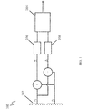
- maximum likelihood angle estimation may be used in a radar system 100 such as one shown in block diagram form in FIG. 1 .
- An antenna 102 receives a signal which is divided into two components ( s 1 , and s 2 ) split into sum and difference channels ( ⁇ and ⁇ ) and supplied to analog-to-digital converters 106.
- a signal processor 104 may be used to analyze the received signals.
- the system 100 may also include filters, oscillators, and other analog and digital signal processing components as are well known in the art.
- Angle estimation of radar returns is often performed with an antenna having two channels: a sum channel and a difference channel.
- the angle of arrival of a received signal (or, equivalently, due to antenna reciprocity theorem, the transmission angle of an outgoing signal) is computed using the sum and difference channels, but the relationship between the angle of arrival and the relative amplitude of the received signal depends on the frequency of the signal when the antenna is steered by adjusting the phase between the elements.
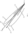
- these angle estimation techniques are generally used with narrowband signals rather than wideband signals because there is not a well defined mapping between angle and relative amplitude of the signal for wideband signals. That is, the wideband signals have a range of frequencies, making it difficult to calculate a single angle of arrival for all of the frequencies. For example, as shown in FIG. 2 , different target angles 210 and 212 may be calculated based at opposing ends of the wideband signal. Therefore, a substantially frequency independent method of determining the angle of arrival would be useful.
- aspects of a maximum likelihood method and system according to embodiments of the present invention are directed to substantially reducing or eliminating deterministic high order angle estimation error caused by beam stabilization in frequency and providing a way to combine multiple observations (e.g., in the case of a radar signal, multiple range or time bins) into a single angle estimate, which can provide an effective reduction of random errors by an improvement in signal to noise ratio.
- W' ⁇ , ⁇ xn are the unsteered amplitudes of the radiating elements that form the phased array antenna
- x p R is the direction cosine defined by the steering phases commanded by the antenna steering hardware. Note that the beam is not necessarily stabilized to the pointing direction commanded by the hardware. Therefore, in general, x o ⁇ x p .
- the "antenna pointing direction" 202 x p R refers to the direction in which the antenna is electronically steered by altering the phases of the signals applied to the antenna.
- the "stabilization direction" 204 x o R refers to the direction in which the beam is stabilized to be substantially frequency independent through the computation of and application of the above-described stabilization coefficients (e.g., m ⁇ , m ⁇ , m ⁇ , and m ⁇ ) to the unstabilized data.
- the stabilization direction is not restricted to the antenna pointing direction and in one embodiment is adjusted to optimize angle estimation.
- the "steering direction” 206 ( ⁇ n ) refers to the direction which is used to calculate the likelihood function for the purpose of angle estimation.
- the "target direction” 208 refers to the true direction to the target, which the system and method attempt to estimate.
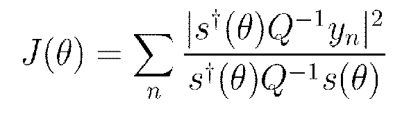
- the maximum likelihood angle estimation technique applies probability theory to determine the most probable angle of arrival of the signal.
- y n is the set of stabilized data vectors from the antennas, which includes s ⁇ and s ⁇
- s ( ⁇ ) is the steering vector corresponding to an angle ⁇ ("steering direction" as defined above)
- Q is the covariance matrix of any undesired signals present, such as noise, interference, or clutter.
- ⁇ is the likelihood steering direction cosine.
- x o R is the direction cosine to which the beam is stabilized.
- the covariance matrix of the desired signals is: ⁇ n y n y n ⁇ ⁇ C y
- the likelihood function when multiple observations or range or time bins are present depends only on the covariance matrix of the data in question.
- the maximum of the likelihood function can be found by finding the zero of its derivative. This may be found using a Newton-Raphson technique.
- the results calculated from this procedure will retain some error due to the beam stabilization transformation.
- the direction of beam stabilization can be adjusted to the newly determined steering angle and the Newton-Raphson iterative procedure can be repeated using the re-stabilized data to calculate a steering angle that is a more accurate estimate of the actual angle of arrival of the signal.
- This process of iteratively adjusting the stabilization direction can be repeated until a stabilization direction accuracy condition has been met (e.g., the difference between successively calculated estimated target angles ⁇ N is less than ⁇ N,th ) , at which point the final estimated target angle is output.
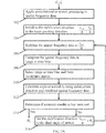
- a method for implementing the above technique can be performed as follows and as illustrated in FIG. 3A .
- a system according to one embodiment of the present invention that may be configured to implement the algorithm of FIG. 3A is shown in FIGS. 4B , 5B, and 5B .
- FIG. 3A is a flowchart illustrating one method of determining an angle to a target from unstabilized spatial frequency data which is formed after initial range processing of the raw data received from an antenna.
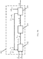
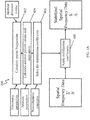
- FIG. 3B is a block diagram illustrating a portion of a signal processor 104 for determining the target angle from the spatial frequency data.
- the signal received from the antenna undergoes transformation into spatial frequency data (e.g., through the first stage of convolutional or stretch processing) (302) at a beam stabilizer 332.
- the direction in which the beam is stabilized x o R is set to (or initialized to) the nominal pointing direction of the antenna array x p R , which is the pointing direction associated with the center frequency of the waveform (304).
- x o , 0 R x p R
- x o , n R refers to the beam stabilization direction during the n th iteration of the loop.
- the stabilization direction is generally different from the antenna pointing direction.
- the unstabilized spatial frequency data s' ⁇ and s' ⁇ is stabilized in the beam stabilization direction x o , n R (306) to produce stabilized spatial frequency data s ⁇ and s ⁇ , after which it is compressed into range or time bins (308) by the beam stabilizer 332. Range or time bins are selected and a covariance matrix is also computed (310) by the beam stabilizer 332.
- the stabilized spatial frequency data s ⁇ and s ⁇ is then supplied with the beam stabilization direction to the steering angle calculator 334.
- the steering angle calculator 334 calculates an angle of arrival ⁇ N using the stabilization direction and the stabilized spatial frequency data (312). As noted above, this calculation results in deterministic error due to the beam stabilization transformation. In order to reduce or eliminate this error, a stabilization direction threshold accuracy calculator 336 compares the newly calculated estimated angle of arrival ⁇ N with the previous estimated angle of arrival (e.g., ⁇ N-1 ) to determine if a stabilization direction accuracy condition has been met (e.g., the difference between two successive estimated angles of arrival is less than a threshold value ⁇ N,th ) (314).
- a stabilization direction accuracy condition e.g., the difference between two successive estimated angles of arrival is less than a threshold value ⁇ N,th
- the stabilization direction is set to the newly calculated estimated angle of arrival (316) and the process is repeated, beginning with the restabilization of the beam in the new stabilization direction (312) by supplying the new stabilization direction to the beam stabilizer 332.
- the newly computed estimated angle of arrival ⁇ N is output as the angle to the target.
- a separate data covariance matrix is determined for each target. For example, if two targets are separated in range, two different groups of range or time bins would be used to form two different covariance matrices.
- FIG. 4A is a flowchart illustrating, in additional detail, one method of stabilizing the spatial frequency data to the beam steering direction.
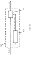
- FIG. 4B is a block diagram illustrating a beam stabilizer 332 according to one embodiment of the present invention.
- the spatial frequencies e.g., s' ⁇ and s' ⁇
- the spatial frequencies are calculated from the spatial frequency data (402) using processing parameters of the signal waveforms (e.g., the characteristics of the transmitted pulse) and the antenna direction.
- antenna parameters e.g., the number and spacing of antenna elements
- antenna pattern values e.g., element amplitudes or weights of the antenna elements
- derivatives of the spatial frequencies are also calculated (404).
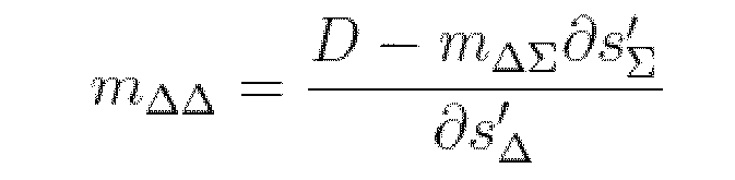
- Normalization constants are used to solve for stabilization coefficients (e.g., m ⁇ , m ⁇ , m ⁇ , and m ⁇ , as described above) (406) by a stabilization coefficient calculator 432.
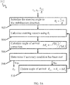
- FIG. 5A is a flowchart illustrating a method of calculating a steering angle according to one embodiment of the present invention.
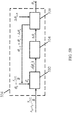
- FIG. 5B is a block diagram illustrating a steering angle calculator 334 according to one embodiment of the present invention which uses the Newton-Raphson method described above to estimate the angle of arrival.
- individual hardware components may be implemented as specialized discrete chips (such as digital signal processors, analog or digital filters, and field programmable gate arrays), general purpose processors programmed to perform the functions of the shown components, or combinations thereof.
- specialized discrete chips such as digital signal processors, analog or digital filters, and field programmable gate arrays
- general purpose processors programmed to perform the functions of the shown components, or combinations thereof.
Landscapes
- Engineering & Computer Science (AREA)
- Radar, Positioning & Navigation (AREA)
- Remote Sensing (AREA)
- Physics & Mathematics (AREA)
- General Physics & Mathematics (AREA)
- Computer Networks & Wireless Communication (AREA)
- Radar Systems Or Details Thereof (AREA)
- Variable-Direction Aerials And Aerial Arrays (AREA)
Abstract
Description
- This invention disclosure is related to Government contract FA8650-08-D-1446 awarded by the Department of the Air Force. The Government has certain rights in this invention.
- Maximum likelihood angle estimation is a technique which may be used in the context of radar for determining an angle of arrival of a signal in a radar or other radio frequency electromagnetic sensor.
- Generally, the algorithm that performs the angle estimation using maximum likelihood estimation relies on the assumption that the estimated target angle does not substantially vary as a function of the frequencies that make up the signal. However, this assumption does not hold true for wideband or spread spectrum waveforms or signals when they are measured by an electronically scanned phased array antenna.
- Embodiments of the present invention are directed to systems and methods which use maximum likelihood analysis to estimate a target angle, the systems and methods being substantially frequency invariant even when used with phase steered antennas and wideband waveforms.
- According to one embodiment of the present invention, a method for estimating a target direction of a wideband signal received on an electronically steered array includes: applying convolutional or stretch processing to spatial frequency data of the wideband signal; initializing a stabilization direction to a beam pointing direction; stabilizing the spatial frequency data to the stabilization direction; compressing the spatial frequency data to a plurality of frequency range or time bins; selecting range or time bins and forming a covariance matrix; calculating an estimated target direction using the covariance matrix; determining if a stabilization direction accuracy condition is met; recalculating the stabilization direction based on the estimated target direction if the stabilization direction accuracy condition is not met; and iteratively repeating stabilizing the spatial frequency data to the stabilization direction, compressing the spatial frequency data to a plurality of frequency range or time bins, calculating an estimated target direction using the covariance matrix, and recalculating the stabilization direction based on the estimated target direction until the stabilization direction accuracy condition is met.
- According to another embodiment of the present invention, a system for stabilizing wideband spatial frequency data of a wideband signal for estimating a target direction on an electronically steered antenna array includes: a beam stabilizer configured to stabilize the spatial frequency data in a stabilization direction; a steering angle calculator configured to estimate the target direction using the stabilized spatial frequency data; a stabilization angle accuracy threshold calculator for determining whether a stabilization direction accuracy condition is met; and a stabilization angle updater for updating the stabilization direction to the estimated target direction, wherein the steering angle calculator is configured to initialize the stabilization direction to a beam pointing direction and to iteratively update the stabilization angle and to recalculate the estimated target direction until the stabilization accuracy condition is met.
- The accompanying drawings, together with the specification, illustrate exemplary embodiments of the present invention, and, together with the description, serve to explain the principles of the present invention.
-
FIG. 1 is a block diagram of a radar system according to one embodiment of the present invention. -
FIG. 2 is a diagram illustrating various directions or angles associated with the system, including a nominal beam pointing direction, a target direction, and a stabilization direction, overlaid on target angles calculated using an unstabilized beam. -
FIG. 3A is a flowchart illustrating a method of determining an angle to a target from unstabilized spatial frequency data according to one embodiment of the present invention. -
FIG. 3B is a block diagram illustrating a signal processor for determining a target angle from unstabilized spatial frequency data according to one embodiment of the present invention. -
FIG. 4A is a flowchart illustrating a method of stabilizing spatial frequency data according to one embodiment of the present invention. -
FIG. 4B is a block diagram illustrating a signal stabilizer according to one embodiment of the present invention. -
FIG. 5A is a flowchart illustrating a method of calculating a steering angle according to one embodiment of the present invention. -
FIG. 5B is a block diagram illustrating a steering angle calculator according to one embodiment of the present invention. - According to one embodiment of the present invention, maximum likelihood angle estimation may be used in a
radar system 100 such as one shown in block diagram form inFIG. 1 . Anantenna 102 receives a signal which is divided into two components (s 1, and s 2) split into sum and difference channels (Σ and Δ) and supplied to analog-to-digital converters 106. Asignal processor 104 may be used to analyze the received signals. Thesystem 100 may also include filters, oscillators, and other analog and digital signal processing components as are well known in the art. - Angle estimation of radar returns is often performed with an antenna having two channels: a sum channel and a difference channel. The angle of arrival of a received signal (or, equivalently, due to antenna reciprocity theorem, the transmission angle of an outgoing signal) is computed using the sum and difference channels, but the relationship between the angle of arrival and the relative amplitude of the received signal depends on the frequency of the signal when the antenna is steered by adjusting the phase between the elements. As a result, these angle estimation techniques are generally used with narrowband signals rather than wideband signals because there is not a well defined mapping between angle and relative amplitude of the signal for wideband signals. That is, the wideband signals have a range of frequencies, making it difficult to calculate a single angle of arrival for all of the frequencies. For example, as shown in
FIG. 2 ,different target angles - One such system and method is described in "Beam Stabilization for Wideband Phase Comparison Monopulse Angle Estimation with Electronically Steered Antennas,"
U.S. Patent Application No. 12/925,668 filed on October 26, 2010 - Aspects of a maximum likelihood method and system according to embodiments of the present invention are directed to substantially reducing or eliminating deterministic high order angle estimation error caused by beam stabilization in frequency and providing a way to combine multiple observations (e.g., in the case of a radar signal, multiple range or time bins) into a single angle estimate, which can provide an effective reduction of random errors by an improvement in signal to noise ratio.
- Stabilization of the beam in frequency space so that frequency elements of the beam point in a consistent direction is used in order to apply the angle estimation technique to wideband signals. Beam stabilization is discussed in more depth in the above referenced patent application. To summarize, the matrix elements for beam stabilization as a function of frequency are given by:



- Assuming we are only solving for on angle of arrival, in the above expressions:

and
where we have defined:

and

where when two signals (s 1, and s 2) are received on corresponding halves of an antenna, s' ∑ is a sum channel and s' Δ is a difference channel (e.g.,


where W' ∑,Δxn are the unsteered amplitudes of the radiating elements that form the phased array antenna and
- A derivation of the above equations appears in "Beam Stabilization for Wideband Phase Comparison Monopulse Angle Estimation with Electronically Steered Antennas," which was incorporated by reference, above.
- Note that there are a few different relevant angles (or "directions") involved in this system, as illustrated in
FIG. 2 : - The "antenna pointing direction" 202

- The "stabilization direction" 204

- The "steering direction" 206 (θ n ) refers to the direction which is used to calculate the likelihood function for the purpose of angle estimation.
- The "target direction" 208 refers to the true direction to the target, which the system and method attempt to estimate.
- The maximum likelihood angle estimation technique applies probability theory to determine the most probable angle of arrival of the signal. In particular, the most probable angle of arrival of the signal occurs at the maximum of the following likelihood function (which is related to the logarithm of the probability distribution function):
- The steering vector s(θ) can be written:

where, in this case, θ is the likelihood steering direction cosine. Recall that
- The likelihood function can be rewritten:

where we have used the fact that Q is Hermetian. Because only yn depends on n, the summation can be brought inside the product:
- Therefore, the covariance matrix of the desired signals is:

- Therefore, the likelihood function when multiple observations or range or time bins are present depends only on the covariance matrix of the data in question.
- The maximum of the likelihood function can be found by finding the zero of its derivative. This may be found using a Newton-Raphson technique. The derivative of the likelihood function is:

which is zero when the numerator is zero. Therefore, we would like to find the zero of:
- Near its zero, this function can be approximated to first order by

where:
- Therefore, the Newton-Raphson iterative procedure is:

- That is, the Newton-Raphson iterative procedure is used to produce successive values of θ n until the calculated angle of arrival

- However, the results calculated from this procedure will retain some error due to the beam stabilization transformation. To reduce or eliminate this error, the direction of beam stabilization can be adjusted to the newly determined steering angle and the Newton-Raphson iterative procedure can be repeated using the re-stabilized data to calculate a steering angle that is a more accurate estimate of the actual angle of arrival of the signal. This process of iteratively adjusting the stabilization direction can be repeated until a stabilization direction accuracy condition has been met (e.g., the difference between successively calculated estimated target angles θ N is less than Δθ N,th ), at which point the final estimated target angle is output.
- According to one embodiment of the present invention, a method for implementing the above technique can be performed as follows and as illustrated in
FIG. 3A . A system according to one embodiment of the present invention that may be configured to implement the algorithm ofFIG. 3A is shown inFIGS. 4B ,5B, and 5B . -
FIG. 3A is a flowchart illustrating one method of determining an angle to a target from unstabilized spatial frequency data which is formed after initial range processing of the raw data received from an antenna.FIG. 3B is a block diagram illustrating a portion of asignal processor 104 for determining the target angle from the spatial frequency data. The signal received from the antenna undergoes transformation into spatial frequency data (e.g., through the first stage of convolutional or stretch processing) (302) at abeam stabilizer 332. - Initially, the direction in which the beam is stabilized


- The unstabilized spatial frequency data s' Δ and s' ∑ is stabilized in the beam stabilization direction

beam stabilizer 332. Range or time bins are selected and a covariance matrix is also computed (310) by thebeam stabilizer 332. The stabilized spatial frequency data s Δ and s ∑ is then supplied with the beam stabilization direction to thesteering angle calculator 334. - The
steering angle calculator 334 calculates an angle of arrival θ N using the stabilization direction and the stabilized spatial frequency data (312). As noted above, this calculation results in deterministic error due to the beam stabilization transformation. In order to reduce or eliminate this error, a stabilization directionthreshold accuracy calculator 336 compares the newly calculated estimated angle of arrival θ N with the previous estimated angle of arrival (e.g., θ N-1 ) to determine if a stabilization direction accuracy condition has been met (e.g., the difference between two successive estimated angles of arrival is less than a threshold value Δθ N,th ) (314). If the stabilization direction accuracy condition is not satisfied, then the stabilization direction is set to the newly calculated estimated angle of arrival (316) and the process is repeated, beginning with the restabilization of the beam in the new stabilization direction (312) by supplying the new stabilization direction to thebeam stabilizer 332. When the stabilization direction accuracy condition is satisfied, the newly computed estimated angle of arrival θ N is output as the angle to the target. When working with multiple targets, a separate data covariance matrix is determined for each target. For example, if two targets are separated in range, two different groups of range or time bins would be used to form two different covariance matrices. -
FIG. 4A is a flowchart illustrating, in additional detail, one method of stabilizing the spatial frequency data to the beam steering direction.FIG. 4B is a block diagram illustrating abeam stabilizer 332 according to one embodiment of the present invention. The spatial frequencies (e.g., s' Δ and s' ∑) are calculated from the spatial frequency data (402) using processing parameters of the signal waveforms (e.g., the characteristics of the transmitted pulse) and the antenna direction. Using antenna parameters (e.g., the number and spacing of antenna elements), antenna pattern values (e.g., element amplitudes or weights of the antenna elements) and derivatives of the spatial frequencies are also calculated (404). Normalization constants are used to solve for stabilization coefficients (e.g., m Δ∑, m ΔΔ , m ∑Δ , and m ∑∑, as described above) (406) by astabilization coefficient calculator 432. The stabilization coefficients (which may be expressed as a combination matrix) are applied to the spatial frequency data (e.g., s' Δ and s' ∑) by a combiner (or matrix multiplier) 434 to obtain the stabilized spatial frequency data stabilized in the stabilization direction (e.g., s Δ = m ΔΔ s' Δ + m Δ∑ s' and s ∑ = m ∑Δ s' Δ + m ∑∑ s' ∑) (408). -
FIG. 5A is a flowchart illustrating a method of calculating a steering angle according to one embodiment of the present invention.FIG. 5B is a block diagram illustrating asteering angle calculator 334 according to one embodiment of the present invention which uses the Newton-Raphson method described above to estimate the angle of arrival. - The
steering angle calculator 334 includes asteering vector calculator 532 which initializes the steering vectors θ n to the stabilization direction

angle correction calculator 534 then uses the steering vectors s(θ n ) to calculate an angle of arrival correction Δθ n (506), where, as derived above:
- An angle of
arrival accuracy calculator 536 compares the angle of arrival correction Δθ n with an angle of arrival accuracy condition Δθ n,th (508). If the angle of arrival accuracy condition is not satisfied (e.g., Δθ n > Δθ n,th ), a new estimate of the angle of arrival θ n+1 is computed by applying the Newton-Raphson iterative procedure described above using the expression:
and the improved target angle estimate θ n+1 is supplied to thesteering vector calculator 532 in order to generate new steering vectors (e.g., s(θ n+1 )) (510). This process is repeated until the angle of arrival accuracy condition Δθ n,th is met and the estimate of the target angle θ N is output by thesteering angle calculator 334. - While the present invention has been described in reference to certain exemplary embodiments, it is to be understood to those skilled in the art that the invention is not limited to the disclosed embodiment, but, on the contrary, is intended to cover various modifications included within the spirit and scope of the appended claims and equivalents thereof.
- For example, individual hardware components (such as those shown in the embodiments depicted in
FIGS. 1 ,4B ,5B, and 5B ) may be implemented as specialized discrete chips (such as digital signal processors, analog or digital filters, and field programmable gate arrays), general purpose processors programmed to perform the functions of the shown components, or combinations thereof.
Claims (9)
- A method for estimating a target direction of a wideband signal received on an electronically steered array, the method comprising:applying convolutional or stretch processing to spatial frequency data of the wideband signal;initializing a stabilization direction to a beam pointing direction;stabilizing the spatial frequency data to the stabilization direction;compressing the spatial frequency data to a plurality of frequency range or time bins;selecting range or time bins and forming a covariance matrix;calculating an estimated target direction using the covariance matrix;determining if a stabilization direction accuracy condition is met;recalculating the stabilization direction based on the estimated target direction if the stabilization direction accuracy condition is not met; anditeratively repeating stabilizing the spatial frequency data to the stabilization direction, compressing the spatial frequency data to a plurality of frequency range or time bins, calculating an estimated target direction using the covariance matrix, and recalculating the stabilization direction based on the estimated target direction until the stabilization direction accuracy condition is met.
- The method of claim 1, wherein the stabilizing the spatial frequency data to the beam steering direction comprises:calculating the spatial frequency data using processing parameters and antenna direction cosine;calculating derivatives of the spatial frequency data and antenna pattern values using antenna parameters;solving for a plurality of stabilization coefficients using normalization constants; andapplying the plurality of stabilization coefficients to the spatial frequency data to generate the stabilized spatial frequency data.
- The method of claim 1, wherein the calculating the estimated target direction based on the stabilized spatial frequency data comprises:initializing a steering angle to the stabilization direction;calculating a plurality of steering vectors using the steering angle;calculating an angle of arrival correction,determining if an angle of arrival accuracy condition has been met;updating the steering angle based on the angle of arrival correction if the angle of arrival accuracy condition is not met;iteratively repeating calculating the steering vectors using the steering angle, calculating the angle of arrival correction, determining if the angle of arrival accuracy condition has been met, and updating the steering angle based on the target direction until a steering angle accuracy condition is met; andoutputting the updated steering angle as the estimated target direction when the steering angle accuracy condition is met.
- The method of claim 1, wherein the target direction comprises a plurality of target directions.
- The method of claim 1, wherein the compressing the stabilized spatial frequency data comprises applying an inverse Fourier transform to the stabilized spatial frequency data.
- A system for stabilizing wideband spatial frequency data of a wideband signal for estimating a target direction on an electronically steered antenna array, the system comprising:a beam stabilizer configured to stabilize the spatial frequency data in a stabilization direction;a steering angle calculator configured to estimate the target direction using the stabilized spatial frequency data;a stabilization angle accuracy threshold calculator for determining whether a stabilization direction accuracy condition is met; anda stabilization angle updater for updating the stabilization direction to the estimated target direction,wherein the steering angle calculator is configured to initialize the stabilization direction to a beam pointing direction and to iteratively update the stabilization angle and to recalculate the estimated target direction until the stabilization accuracy condition is met.
- The system of claim 6, wherein the steering angle calculator comprises:a steering vector calculator configured to calculate a steering vector using the stabilized spatial frequency data;an angle correction calculator configured to calculate an angle of arrival correction using the steering vector; andan angle of arrival accuracy calculator configured to compare the angle of arrival correction with an angle of arrival accuracy condition.
- The system of claim 6, wherein the beam stabilizer comprises:a stabilization coefficient calculator configured to calculate a plurality of stabilization coefficients; anda combiner configured to combine the spatial frequency data with the plurality of stabilization coefficients to generate stabilized spatial frequency data.
- The system of claim 6, wherein the steering angle calculator is configured to:initialize a steering angle to the stabilization direction;calculate a plurality of steering vectors using the steering angle;calculate an angle of arrival correction;determine if an angle of arrival accuracy condition has been met;update the steering angle based on the angle of arrival correction if the angle of arrival accuracy condition has been met;iteratively repeat calculating the steering vectors using the steering angle, calculating the angle of arrival correction, determining if the angle of arrival accuracy condition has been met, and updating the steering angle using the steering vectors, and updating the steering angle based on the angle of arrival correction until a steering angle accuracy condition is met; andoutput the updated steering angle as the estimated target direction when the steering angle accuracy condition is met.
Applications Claiming Priority (1)
| Application Number | Priority Date | Filing Date | Title |
|---|---|---|---|
| US13/092,073 US8451173B2 (en) | 2011-04-21 | 2011-04-21 | Maximum likelihood angle estimation of wideband signals using phased array antennas |
Publications (2)
| Publication Number | Publication Date |
|---|---|
| EP2515142A2 true EP2515142A2 (en) | 2012-10-24 |
| EP2515142A3 EP2515142A3 (en) | 2013-01-16 |
Family
ID=45655736
Family Applications (1)
| Application Number | Title | Priority Date | Filing Date |
|---|---|---|---|
| EP12155386A Withdrawn EP2515142A3 (en) | 2011-04-21 | 2012-02-14 | Maximum likelihood angle estimation of wideband signals using phased array antennas |
Country Status (2)
| Country | Link |
|---|---|
| US (2) | US8451173B2 (en) |
| EP (1) | EP2515142A3 (en) |
Families Citing this family (12)
| Publication number | Priority date | Publication date | Assignee | Title |
|---|---|---|---|---|
| US8451173B2 (en) * | 2011-04-21 | 2013-05-28 | Raytheon Company | Maximum likelihood angle estimation of wideband signals using phased array antennas |
| US10101445B2 (en) * | 2014-04-29 | 2018-10-16 | Research Foundation Of The City University Of New York | Power centroid radar |
| US9891310B2 (en) | 2015-04-02 | 2018-02-13 | Raytheon Company | Sequential multi-beam radar for maximum likelihood tracking and fence search |
| US10310063B2 (en) * | 2015-05-12 | 2019-06-04 | Maxlinear, Inc. | Calibration of a multifunctional automotive radar system |
| CN105445709B (en) * | 2015-11-12 | 2017-11-17 | 电子科技大学 | A kind of thinning array near field passive location amplitude and phase error correction method |
| CN105510884B (en) * | 2015-12-08 | 2018-11-30 | 北京无线电计量测试研究所 | A kind of image processing method and equipment |
| CN106066471A (en) * | 2016-06-01 | 2016-11-02 | 安徽建筑大学 | The localization method of a kind of mobile target and system |
| JP6863011B2 (en) | 2017-03-31 | 2021-04-21 | トヨタ自動車株式会社 | Steering control device |
| JP2019168290A (en) * | 2018-03-22 | 2019-10-03 | パナソニックIpマネジメント株式会社 | Radar device, position estimation device, and position estimation method |
| US12442895B2 (en) * | 2021-09-30 | 2025-10-14 | Nxp B.V. | Determining reliability of a direction of arrival (DOA) of a signal received by a radar system from a source and apparatus for determining reliability |
| CN119004719B (en) * | 2024-08-09 | 2025-04-04 | 内蒙古高新科技控股有限责任公司 | Frequency-invariant antenna array optimization method and device based on amplitude spectrum analysis |
| CN120429659B (en) * | 2025-07-04 | 2025-09-23 | 华南理工大学 | Broadband incoherent distributed source two-dimensional parameter estimation method based on spectrum matching |
Citations (1)
| Publication number | Priority date | Publication date | Assignee | Title |
|---|---|---|---|---|
| US5381151A (en) * | 1994-02-02 | 1995-01-10 | Grumman Aerospace Corporation | Signal processing for ultra-wideband impulse radar |
Family Cites Families (11)
| Publication number | Priority date | Publication date | Assignee | Title |
|---|---|---|---|---|
| US2608683A (en) | 1943-10-28 | 1952-08-26 | Gen Electric | Phase comparison object locating system |
| US2981948A (en) | 1956-05-29 | 1961-04-25 | Hughes Aircraft Co | Simultaneous lobing array antenna system |
| US3713155A (en) | 1958-06-23 | 1973-01-23 | Hughes Aircraft Co | Monopulse radar receiver |
| US5223850A (en) | 1988-10-24 | 1993-06-29 | Hughes Aircraft Company | Low-profile full aperture monopulse antenna assembly |
| US5592178A (en) | 1994-06-01 | 1997-01-07 | Raytheon Company | Wideband interference suppressor in a phased array radar |
| US5945940A (en) | 1998-03-12 | 1999-08-31 | Massachusetts Institute Of Technology | Coherent ultra-wideband processing of sparse multi-sensor/multi-spectral radar measurements |
| SG80071A1 (en) | 1999-09-24 | 2001-04-17 | Univ Singapore | Downlink beamforming method |
| US6624783B1 (en) * | 2001-02-28 | 2003-09-23 | Massachusetts Institute Of Technology | Digital array stretch processor employing two delays |
| US6653973B2 (en) * | 2001-09-07 | 2003-11-25 | Lockheed Martin Corporation | Adaptive digital beamforming radar method and system for maintaining multiple source angle super-resolution capability in jamming |
| JP4447946B2 (en) | 2004-03-22 | 2010-04-07 | 富士通テン株式会社 | Radar equipment |
| US8451173B2 (en) * | 2011-04-21 | 2013-05-28 | Raytheon Company | Maximum likelihood angle estimation of wideband signals using phased array antennas |
-
2011
- 2011-04-21 US US13/092,073 patent/US8451173B2/en active Active
-
2012
- 2012-02-14 EP EP12155386A patent/EP2515142A3/en not_active Withdrawn
-
2013
- 2013-05-07 US US13/889,144 patent/US9391365B2/en active Active
Patent Citations (1)
| Publication number | Priority date | Publication date | Assignee | Title |
|---|---|---|---|---|
| US5381151A (en) * | 1994-02-02 | 1995-01-10 | Grumman Aerospace Corporation | Signal processing for ultra-wideband impulse radar |
Non-Patent Citations (1)
| Title |
|---|
| NINGKUN PENG ET AL: "Multipath signals tracking for frequency hopping systems", PROCEEDINGS / 2004 IEEE 59TH VEHICULAR TECHNOLOGY CONFERENCE, VTC 2004-SPRING : TOWARDS A GLOBAL WIRELESS WORLD ; 17 - 19 MAY 2004, MILAN, ITALY, IEEE OPERATIONS CENTER, PISCATAWAY, NJ, vol. 1, 17 May 2004 (2004-05-17), pages 84 - 87, XP010764771, ISBN: 978-0-7803-8255-8, DOI: 10.1109/VETECS.2004.1387917 * |
Also Published As
| Publication number | Publication date |
|---|---|
| US20120268325A1 (en) | 2012-10-25 |
| US9391365B2 (en) | 2016-07-12 |
| EP2515142A3 (en) | 2013-01-16 |
| US8451173B2 (en) | 2013-05-28 |
| US20140132451A1 (en) | 2014-05-15 |
Similar Documents
| Publication | Publication Date | Title |
|---|---|---|
| US8451173B2 (en) | Maximum likelihood angle estimation of wideband signals using phased array antennas | |
| KR102449214B1 (en) | Apparatus for estimating angle of arrival and method for estimating angle of arrival using same | |
| US6603424B1 (en) | System, method and computer program product for reducing errors in synthetic aperture radar signals | |
| US8354960B2 (en) | Method for low sidelobe operation of a phased array antenna having failed antenna elements | |
| US10481242B2 (en) | Method for joint antenna-array calibration and direction of arrival estimation for automotive applications | |
| CN108398669B (en) | A space-time broadband adaptive monopulse angle measurement method without pre-delay processing | |
| US7064702B1 (en) | System, method and computer program product for reducing quadratic phase errors in synthetic aperture radar signals | |
| CN104345306B (en) | Target wave arrival angle estimation method based on Khatri-Rao subspace | |
| CN113093173A (en) | Beamforming techniques to implement Iterative Adaptive Approach (IAA) | |
| CN105137425B (en) | The preceding visual angle ultra-resolution method of scanning radar based on Deconvolution principle | |
| CN108710103B (en) | Strong and weak multi-target super-resolution direction finding and information source number estimation method based on sparse array | |
| CN113673158B (en) | Beam domain variation Bayesian azimuth estimation method suitable for strong interference environment | |
| CN106842114A (en) | Target direction of arrival acquisition methods based on root MUSIC algorithms | |
| CN107607915B (en) | Active phased array radar receiving channel correction method based on fixed ground object echo | |
| KR101144012B1 (en) | Phased array antenna system providing nulling in the direction of jammer and control method of the same | |
| CN118033613A (en) | Two-dimensional super-resolution detection method based on line spectrum estimation problem of equally spaced circular array | |
| CN105572629B (en) | A kind of two-dimentional direction-finding method of low computational complexity suitable for General Cell structure | |
| CN106125039B (en) | Improvement space-time adaptive Monopulse estimation method based on local Combined Treatment | |
| KR101793340B1 (en) | Method and Apparatus for optimum power transmit and transmit beamforming for wideband array antenna based on Diagonal Loaded Least Mean Square method | |
| CN115144823A (en) | A space-time robust clutter suppression method for high-frequency ground-wave radar based on compressed sensing | |
| US11181605B2 (en) | Method and device for estimating an angle of arrival of an incident radio signal | |
| CN106844886B (en) | Target direction of arrival acquisition method based on principal component analysis | |
| CN113820681B (en) | A Dictionary Correction Method in Airborne Radar Sparse Restoration-like STAP Algorithm | |
| JP7433535B2 (en) | Signal processing device, radar device, and signal processing method | |
| Fidelman et al. | Correction of radiation pattern due to antenna reflector deformation in passive monopulse direction finding problem |
Legal Events
| Date | Code | Title | Description |
|---|---|---|---|
| PUAI | Public reference made under article 153(3) epc to a published international application that has entered the european phase |
Free format text: ORIGINAL CODE: 0009012 |
|
| 17P | Request for examination filed |
Effective date: 20120312 |
|
| AK | Designated contracting states |
Kind code of ref document: A2 Designated state(s): AL AT BE BG CH CY CZ DE DK EE ES FI FR GB GR HR HU IE IS IT LI LT LU LV MC MK MT NL NO PL PT RO RS SE SI SK SM TR |
|
| AX | Request for extension of the european patent |
Extension state: BA ME |
|
| PUAL | Search report despatched |
Free format text: ORIGINAL CODE: 0009013 |
|
| AK | Designated contracting states |
Kind code of ref document: A3 Designated state(s): AL AT BE BG CH CY CZ DE DK EE ES FI FR GB GR HR HU IE IS IT LI LT LU LV MC MK MT NL NO PL PT RO RS SE SI SK SM TR |
|
| AX | Request for extension of the european patent |
Extension state: BA ME |
|
| RIC1 | Information provided on ipc code assigned before grant |
Ipc: G01S 13/42 20060101ALI20121207BHEP Ipc: G01S 7/295 20060101ALI20121207BHEP Ipc: G01S 3/32 20060101ALI20121207BHEP Ipc: G01S 13/02 20060101AFI20121207BHEP Ipc: G01S 13/44 20060101ALI20121207BHEP Ipc: G01S 3/46 20060101ALI20121207BHEP |
|
| 17Q | First examination report despatched |
Effective date: 20151208 |
|
| STAA | Information on the status of an ep patent application or granted ep patent |
Free format text: STATUS: THE APPLICATION IS DEEMED TO BE WITHDRAWN |
|
| 18D | Application deemed to be withdrawn |
Effective date: 20160419 |