EP2515078A2 - Systèmes et procédés de navigation dans un environnement sans GPS - Google Patents
Systèmes et procédés de navigation dans un environnement sans GPS Download PDFInfo
- Publication number
- EP2515078A2 EP2515078A2 EP12163511A EP12163511A EP2515078A2 EP 2515078 A2 EP2515078 A2 EP 2515078A2 EP 12163511 A EP12163511 A EP 12163511A EP 12163511 A EP12163511 A EP 12163511A EP 2515078 A2 EP2515078 A2 EP 2515078A2
- Authority
- EP
- European Patent Office
- Prior art keywords
- terrain
- user interface
- navigation system
- navigation
- user
- Prior art date
- Legal status (The legal status is an assumption and is not a legal conclusion. Google has not performed a legal analysis and makes no representation as to the accuracy of the status listed.)
- Withdrawn
Links
Images


Classifications
-
- G—PHYSICS
- G01—MEASURING; TESTING
- G01C—MEASURING DISTANCES, LEVELS OR BEARINGS; SURVEYING; NAVIGATION; GYROSCOPIC INSTRUMENTS; PHOTOGRAMMETRY OR VIDEOGRAMMETRY
- G01C21/00—Navigation; Navigational instruments not provided for in groups G01C1/00 - G01C19/00
- G01C21/10—Navigation; Navigational instruments not provided for in groups G01C1/00 - G01C19/00 by using measurements of speed or acceleration
- G01C21/12—Navigation; Navigational instruments not provided for in groups G01C1/00 - G01C19/00 by using measurements of speed or acceleration executed aboard the object being navigated; Dead reckoning
- G01C21/16—Navigation; Navigational instruments not provided for in groups G01C1/00 - G01C19/00 by using measurements of speed or acceleration executed aboard the object being navigated; Dead reckoning by integrating acceleration or speed, i.e. inertial navigation
- G01C21/183—Compensation of inertial measurements, e.g. for temperature effects
- G01C21/188—Compensation of inertial measurements, e.g. for temperature effects for accumulated errors, e.g. by coupling inertial systems with absolute positioning systems
-
- G—PHYSICS
- G01—MEASURING; TESTING
- G01C—MEASURING DISTANCES, LEVELS OR BEARINGS; SURVEYING; NAVIGATION; GYROSCOPIC INSTRUMENTS; PHOTOGRAMMETRY OR VIDEOGRAMMETRY
- G01C21/00—Navigation; Navigational instruments not provided for in groups G01C1/00 - G01C19/00
- G01C21/20—Instruments for performing navigational calculations
-
- G—PHYSICS
- G01—MEASURING; TESTING
- G01C—MEASURING DISTANCES, LEVELS OR BEARINGS; SURVEYING; NAVIGATION; GYROSCOPIC INSTRUMENTS; PHOTOGRAMMETRY OR VIDEOGRAMMETRY
- G01C23/00—Combined instruments indicating more than one navigational value, e.g. for aircraft; Combined measuring devices for measuring two or more variables of movement, e.g. distance, speed or acceleration
Definitions
- GPS Global Positioning System
- supplemental sensors such as inertial sensors, radio navigation aids, optical scene correlators (e.g. Digital Scene Matching Correlator (DSMAC)), radar/terrain correlators (e.g., Precision Terrain Aided Navigation (PTAN)), and the like.
- DSMAC Digital Scene Matching Correlator
- PTAN Precision Terrain Aided Navigation
- Embodiments of the present invention provide systems and methods for navigation in a GPS-denied environment and will be understood by reading and studying the following specification.
- a system includes: a navigation system configured to provide a navigational solution; at least one memory device configured to store a terrain object database, the terrain object database storing information that describes a terrain; a user interface configured to display a terrain model and receive position adjustments from a user; and a processing unit configured to generate displayable information for displaying the terrain model using the information stored on the at least one memory device and the navigational solution, and calculate corrections to the navigational solution from the position adjustments and transmit the corrections to the navigation system.
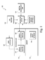
- Figure 1 is a block diagram of one embodiment of a system for providing navigation in a GPS denied environment.
- Figure 2 is a block diagram illustrating the use of a system for providing navigation in a GPS denied environment according to one embodiment.
- Figures 3A-C are diagrams illustrating rendered information on a terrain display with added symbologies according to one embodiment.
- Figure 4 is a flow diagram illustrating one embodiment of a method for providing navigation in a GPS denied environment.
- FIG. 1 is a block diagram of one embodiment of a system 100 for updating a navigational solution in a GPS denied environment.
- System 100 includes navigation system 102.
- navigation system 102 uses information about current position in conjunction with information gathered from an inertial measurement unit (IMU) 116.
- IMU 116 includes gyroscopes, accelerometers, and other instrumentation that provide motion information to navigation system 102.
- navigation system 102 Upon receiving the motion information from IMU 116, navigation system 102 calculates a navigation solution, which includes the position, velocity, heading, and attitude of a navigating object. For example, navigation system 102 can calculate the position, velocity, heading, and attitude of an airplane, a boat, a car, and the like.
- navigation system 102 receives navigational corrections from the GPS through GPS receiver 118.
- the navigational corrections received from the GPS, through GPS receiver 118 correct the drifting errors such that navigation system 102 calculates a more accurate navigational solution.
- system 100 includes memory 112.
- Memory 112 includes at least one device that can hold data in a machine readable medium.
- the machine readable medium can be implemented as any available media that can be accessed by a general purpose or special purpose computer or processor, or any programmable logic device. Suitable machine or processor readable media may include storage/memory media such as magnetic or optical media.
- storage/memory media may include conventional hard disks, Compact Disk - Read Only Memory (CD-ROM), volatile or non-volatile media such as Random Access Memory (RAM) (including, but not limited to, Synchronous Dynamic Random Access Memory (SDRAM), Double Data Rate (DDR) RAM, RAMBUS Dynamic RAM (RDRAM), Static RAM (SRAM), etc.), Read Only Memory (ROM), Electrically Erasable Programmable ROM (EEPROM), and flash memory, etc.
- RAM Random Access Memory
- SDRAM Synchronous Dynamic Random Access Memory
- DDR Double Data Rate
- RDRAM RAMBUS Dynamic RAM
- SRAM Static RAM
- ROM Read Only Memory
- EEPROM Electrically Erasable Programmable ROM
- flash memory etc.
- Suitable processor-readable media may also include transmission media such as electrical, electromagnetic, or digital signals, conveyed via a communication medium such as a network and/or a wireless link.
- Memory 112 stores a terrain object database 104.
- terrain object database refers to a database that stores information describing the terrain through which a navigating object is traveling.
- terrain object database 104 stores information that describes the terrain of the Earth.
- terrain object database 104 can store information described by a Digital Terrain model, a Digital Elevation Model, a Vertical Obstruction Database, a digital surface model and the like.
- terrain object database 104 can store information about regions representing a subset of the earth's terrain. Further, terrain object database 104 resides either on the vehicle or off the vehicle.
- terrain object database 104 When terrain object database 104 resides off the vehicle, terrain object database 104 communicates with the vehicle through a communication link to provide information describing the terrain through which a navigating object travels. Also, terrain object database 104 can store information that describes the terrain that is gathered by sensors on board the airplane. Conversely, terrain object database 104 can store information that is loaded into memory 112 from a compilation of terrain information.
- System 100 also includes a processing unit 114.
- Processing unit 114 includes at least one electronic device that accepts data and performs mathematical and logical operations.
- Processing unit 114 includes or functions with software programs, firmware, or other computer readable instructions for carrying out various methods, process tasks, calculations, and control functions used in implementing the functionality described below. These instructions are typically stored on any appropriate computer or machine readable medium used for storage of computer readable instructions or data structures, such as memory 112.
- Processing unit 114 includes a display generator function 106.
- display generator function refers to a function performed by a processor that uses the information stored in the terrain object database 104 and the navigational solution to generate displayable information that, when displayed, produces a model of the terrain of the environment through which the navigating object travels.
- navigation system 102 provides a navigational solution to display generator function 106.
- display generator function 106 acquires information from terrain object database 104 in memory 112 to create displayable information representing the view from the navigating object with the position, heading, velocity, and attitude described by the navigation solution.
- display generator function 106 uses the navigation solution from navigation system 104 in conjunction with information from terrain object database 104 to generate displayable information representing the view a pilot of the airplane would have if the pilot were to look through the window of the airplane.
- System 100 further includes a user interface 108.
- User interface 108 receives the displayable information from display generator function 106 and creates a visual display for a user. For example, again where the user is a pilot of an airplane, user interface 108 displays a three-dimensional view of the terrain that corresponds with the view of the pilot from the airplane. In an airplane, the user interface 108 can be located on a control panel, above a window, on a head mounted display, and the like. When user interface 108 solely provides a display to the user based on the navigation solution, user interface 108 functions as a display unit of the terrain that is visible to the pilot.
- display generator function 106 adds symbology information to the displayable information that causes user interface 108 to display, in addition to the terrain, symbology markers that correspond to the view from an object. For example, where the object is an airplane, display generator function 106 adds symbology information to the displayable information that causes user interface 108 to render lines and other markings on the terrain display that correspond to the sides of the window. Display generator function 106 also can add information that corresponds to a boresight, a top window edge, a bottom window edge, a nose of a plane, and the like.
- navigation system 102 receives a GPS signal to correct any errors that arise over time in the navigation solution.
- certain environments can prevent system 100 from receiving a GPS signal.
- a malfunction in a GPS receiver or intervening interface can also prevent the reception of a GPS signal.
- system 100 can receive data from navigations sensors 120.
- Navigation sensors 120 provide alternative systems to acquire data that can be used to correct errors that arise in navigation system 102.
- navigation sensors 120 include sensors, like radar, lidar, and the like.
- Navigation system 102 can use the information acquired by navigation sensors 120 to correct errors that arise in navigation system 102 surrounding environment and ascertain the location of system 100.
- sensors in navigation sensors 120 can be expensive and may not be widely available to all aircraft. Therefore, as navigation sensors 120 is not available in all aircraft, alternative means of correcting the errors that arise in the navigation solution may be needed in GPS-denied environments.
- system 100 decouples user interface 108 from display generator function 106.
- decouple refers to the alteration of the functionality of user interface 108 such that the position of the terrain that is displayed on user interface 108 is not exclusively determined by the navigation solution calculated by navigation system 102.
- display generator function 106 determines the displayable terrain based on the navigation solution received from navigation system 102.
- display generator function 106 uses the navigational solution in conjunction with information acquired by user interface 108 to determine what information should be read from terrain object database 104 but user interface 108 allows a user to make position adjustments to the terrain model on user interface 108 to more accurately represent the view from the navigating object.
- user interface 108 is decoupled from display generator function 106, the terrain that is displayed on user interface 108 is determined by the navigation solution calculated by navigation system 102 and position adjustments made to the display by a user of system 100.
- a user can also make position adjustment to the display when system 100 is operating in an environment where GPS corrections are available.
- the terrain displayed on user-interface 108 will drift away from the actual terrain viewed by a user.
- the user can adjust the terrain displayed on user interface 108 such that the terrain displayed on user interface 108 matches the view of a user through a window or other field of view.
- position adjustment refers to an adjustment made on user interface 108 that changes what terrain is displayed on user interface 108.
- user interface 108 displays a terrain image on a touch screen monitor.
- a user can adjust what terrain is displayed on the touchscreen by touching the screen and moving the image until the terrain image on the display matches the view of the user from the navigating object.
- a user can make position adjustments through bezel button bumps, cursor control, and the like.
- Display interface function 110 is a function of processing unit 114 that uses the record of the position adjustments made on user interface 108 to calculate an updated position for the navigating object. For example, a user may make a position adjustment to the display on user interface 108 that represents a change in the altitude of the navigating object. Display interface function 110 uses the position adjustment that represents a change in altitude to calculate a new altitude for the navigating object.
- display interface function 110 When display interface function 110 calculates an updated position for the navigating object, display interface function 110 transmits the updated position to display generator function 106.
- Display generator function 106 uses the updated position to create new displayable information for updating the display on user interface 108. For example, display generator function 106 receives an updated position from display interface function 110.
- display generator function 106 Upon receiving the updated position from display interface function 110, display generator function 106 acquires new terrain information from terrain object database 104 and generates new displayable information that, when rendered by user interface 108, will display the terrain as viewed from the updated position. Further, in some embodiments, display generator function 106 updates the displayable information rendered by user interface 108 in real time.
- display generator function 106 when a user makes position changes on user interface 108, the position changes appear to happen with little to no delay from the viewpoint of the user.
- display generator function 106 generates displayable information that represents a terrain that is larger than the area viewable by a user. By generating a larger terrain, the user can move the terrain model on the terrain display without waiting for display generator function 106 to generate new displayable information.
- display generator function 106 when display generator function 106 receives an updated position from display interface function 110, display generator function 106 transmits the updated position to navigation system 102.
- the navigation solution calculated by navigation system 102 develops errors over time when navigation system 102 operates without receiving corrective information.
- navigation system 102 Upon reception of the updated position from display generator function 106, navigation system 102 uses the updated position to correct errors that have developed during operation.
- Figure 2 illustrates an exemplary implementation of system 100.
- the navigating object provides a terrain display 205 to a user 207.
- Terrain display 205 is part of user interface 108 in figure 1 as described above.
- Terrain display 205 displays a terrain model to user 207 that represents external scene 201.
- the phrase "external scene,” as used herein, refers to the terrain that user 207 sees when looking at the environment surrounding the navigating object. For example, when user 207 is a pilot flying an airplane, external scene 201 would be the pilot's view of the world looking through viewing pane 203 of the airplane at the surrounding environment.
- Viewing pane 203 can be the window at the front of a vehicle, where external scene 201 is the view of user 207 looking over the front of the vehicle.
- viewing pane 203 can be a side window of a vehicle, where external scene 201 is the view of user 207 looking through the side window of the vehicle.
- Viewing pane 203 can provide user 207 a view through the top, bottom, and rear of the vehicle.
- Viewing pane 302 includes a plurality of views from the airplane.
- Viewing pane 203 provides user 207 a combination of views that includes views through at least one of a view through the front, side, bottom, top, and back of the vehicle.
- Position adjuster 209 is an apparatus that allows a user 207 to adjust the terrain model, rendered in terrain display 205, so that it matches user 207's view of external scene 201 through a viewing pane 203, where viewing pane 203 is a window, a hole, another image created by a sensor, and the like.
- position adjuster 209 can be a touchscreen, bezel button bumps, cursor control, and the like.
- Display interface function 110 uses the position adjustments to calculate a new position for the vehicle and update navigation system 102 as described above.
- user interface 108 in figure 1 when the navigating object is in a GPS-denied environment, user interface 108 in figure 1 periodically prompts user 207 in figure 2 to adjust the position of the rendered scene on terrain display 205. For example, when a user 207 adjusts the position of the rendered scene on terrain display 205, display interface function 110 in figure 1 resets a timer. When the timer expires, user interface 108 prompts user 207 to adjust the rendered scene. User interface 108 prompts user 207 by using a flashing light, a text box that appears on terrain display 205, an auditory signal, and the like.
- display generator function 106 can add information to the rendered scene on terrain display 205 that corresponds with the view from a navigating object.
- display generator function 106 adds information to the displayable information that causes user interface 108 to render lines on terrain display 205 that correspond to the sides of a window.
- terrain display 205 provides markings that correspond to elements of the navigating object that are in the field of view of user 207.
- terrain display 205 can have a boresight marking, a series of lines corresponding to window edges, a marking corresponding to the nose of the airplane, and the like.
- Terrain display 205 can also display a combination of multiple different markings representing features in the field of view of user 207. The markings, whether they appear on terrain display 205 or whether they are added to the rendered scene by display generator function 106, aid user 207 in aligning the rendered scene on terrain display 205 with external scene 201 as viewed from the navigating object.
- Figures 3A-C are diagrams illustrating rendered information on a terrain display with added symbologies.
- Figure 3A illustrates a terrain display 305 with information displayed to show a rendered scene 317 through the added symbology of window boundaries 311.
- window boundaries 311 are added to the rendered scene 317 to mimic the view of a user that is looking through the windows of a vehicle at an external environment. Window boundaries 311 aid the user in aligning the rendered scene 317 with the external environment when collecting position adjustments for correcting the navigation system.
- Figure 3B illustrates a terrain display 305 with information displayed to show a rendered scene 317 in relation to an external feature 313 of a vehicle.
- an external portion of the body of the vehicle can be added to rendered scene 317 as external feature 313.
- External feature 313, like window boundaries 311 of figure 3A is added to rendered scene 317 to mimic the view of a user that is looking at an external environment from the vehicle.
- external feature 313 aids the user in aligning the rendered scene 317 with the external environment when collecting position adjustments for correcting the navigation system.
- Figure 3C illustrates a terrain display 305 with information displayed to show a rendered scene 317 in relation to navigational guidance information 315.
- navigational guidance information 315 can be added to rendered scene 317.
- Navigational guidance information 315 includes information that allows the user to align rendered scene 317 with the view of the external environment from the vehicle when collecting position adjustments for correcting the navigation system.
- FIG. 4 is a flow diagram illustrating a method 400 for acquiring navigation information in a GPS denied environment.
- a terrain model is displayed on a user interface.
- a display generator acquires a navigation solution from a navigation system indicating a position of a navigating object.
- the display generator accesses a terrain object database to acquire information describing the viewable terrain from a navigation object with the calculated navigation solution.
- the display generator uses this information to render a terrain model.
- a user interface uses the information received from the display generator to display the terrain model to a user.
- position adjustments to the terrain model are accepted on the user interface.
- the navigation system will progressively accumulate errors.
- the accumulating errors cause the terrain model displayed on the user interface to drift away from accurately representing the viewable terrain.
- the user interface accepts position adjustments to the terrain model on the user interface.
- a navigational correction is calculated for the navigation system using the position adjustments.
- the display interface processor receives the position adjustments from the user interface, calculates a corrected position, and transmits the corrected position to the display generator.
- the display generator updates the terrain model and transmits the corrected position to the navigation system.
- the navigation system is updated with the navigational correction.
Applications Claiming Priority (1)
| Application Number | Priority Date | Filing Date | Title |
|---|---|---|---|
| US13/089,493 US8457882B2 (en) | 2011-04-19 | 2011-04-19 | Systems and methods for navigation in a GPS-denied environment |
Publications (2)
| Publication Number | Publication Date |
|---|---|
| EP2515078A2 true EP2515078A2 (fr) | 2012-10-24 |
| EP2515078A3 EP2515078A3 (fr) | 2014-02-19 |
Family
ID=46052541
Family Applications (1)
| Application Number | Title | Priority Date | Filing Date |
|---|---|---|---|
| EP12163511.4A Withdrawn EP2515078A3 (fr) | 2011-04-19 | 2012-04-09 | Systèmes et procédés de navigation dans un environnement sans GPS |
Country Status (2)
| Country | Link |
|---|---|
| US (1) | US8457882B2 (fr) |
| EP (1) | EP2515078A3 (fr) |
Cited By (5)
| Publication number | Priority date | Publication date | Assignee | Title |
|---|---|---|---|---|
| GB2508617A (en) * | 2012-12-05 | 2014-06-11 | Vert Systems Ltd | Terrain-topography motion capture system, apparatus and method |
| WO2017030813A1 (fr) * | 2015-08-20 | 2017-02-23 | Trimble Navigation Limited | Navigation inertielle sans fil de véhicule avec entrée de données d'altitude |
| CN113074722A (zh) * | 2020-01-03 | 2021-07-06 | 上海航空电器有限公司 | 基于视觉辅助技术对地形参考导航精度提升定位修正方法 |
| EP3951322A1 (fr) * | 2020-08-04 | 2022-02-09 | Honeywell International Inc. | Systèmes et procédés d'étalonnage de position d'un capteur sur un aéronef |
| US11408751B2 (en) | 2020-08-04 | 2022-08-09 | Honeywell International Inc. | Systems and methods for calibrating a sensor position on an aircraft |
Families Citing this family (11)
| Publication number | Priority date | Publication date | Assignee | Title |
|---|---|---|---|---|
| US9151613B2 (en) * | 2011-08-12 | 2015-10-06 | Qualcomm Incorporated | Methods and apparatus for detecting, measuring, and mitigating effects of moving an inertial navigation device's cradle |
| US8766975B2 (en) * | 2012-07-19 | 2014-07-01 | Honeywell International Inc. | Method of correlating images with terrain elevation maps for navigation |
| US9098999B2 (en) * | 2013-09-13 | 2015-08-04 | The Boeing Company | Systems and methods for assuring the accuracy of a synthetic runway presentation |
| US10378900B2 (en) | 2015-09-16 | 2019-08-13 | Raytheon Company | Magnetic field gradient navigation aid |
| US10338261B2 (en) | 2015-09-16 | 2019-07-02 | Raytheon Company | Measurement of magnetic field gradients |
| US10054445B2 (en) | 2016-05-16 | 2018-08-21 | Northrop Grumman Systems Corporation | Vision-aided aerial navigation |
| US9911189B1 (en) * | 2016-06-30 | 2018-03-06 | Kitty Hawk Corporation | Navigation based on downward facing sensors |
| US11698461B1 (en) | 2019-11-20 | 2023-07-11 | Telephonics Corp. | GPS denial detection and reporting and mitigation |
| CN111694021B (zh) * | 2020-05-26 | 2022-08-05 | 中国科学院国家授时中心 | 一种基于gnss环境模型的单站滑坡变形监测预警方法 |
| US11790793B2 (en) | 2021-01-08 | 2023-10-17 | Honeywell International Inc. | Systems and methods for model based vehicle navigation |
| US11781836B2 (en) * | 2021-03-04 | 2023-10-10 | Honeywell International Inc. | Systems and methods for model based inertial navigation for a spinning projectile |
Family Cites Families (23)
| Publication number | Priority date | Publication date | Assignee | Title |
|---|---|---|---|---|
| US5654890A (en) * | 1994-05-31 | 1997-08-05 | Lockheed Martin | High resolution autonomous precision approach and landing system |
| US5566073A (en) * | 1994-07-11 | 1996-10-15 | Margolin; Jed | Pilot aid using a synthetic environment |
| US6606034B1 (en) * | 1995-07-31 | 2003-08-12 | Honeywell International Inc. | Terrain awareness system |
| US5904724A (en) | 1996-01-19 | 1999-05-18 | Margolin; Jed | Method and apparatus for remotely piloting an aircraft |
| US5995903A (en) * | 1996-11-12 | 1999-11-30 | Smith; Eric L. | Method and system for assisting navigation using rendered terrain imagery |
| US6442481B2 (en) * | 2000-07-28 | 2002-08-27 | Honeywell International Inc. | Second order complementary global positioning system/inertial navigation system blending filter |
| US20030132860A1 (en) * | 2001-09-21 | 2003-07-17 | Honeywell International, Inc. | Interface for visual cueing and control for tactical flightpath management |
| GB2380793B (en) * | 2001-10-10 | 2005-03-09 | Roke Manor Research | Positioning system |
| US7089092B1 (en) * | 2002-07-18 | 2006-08-08 | Rockwell Collins, Inc. | Airborne system and method for improving the integrity of electronic landing aids |
| US7519469B2 (en) * | 2005-04-28 | 2009-04-14 | Alpine Electronics, Inc. | Display method and apparatus for navigation system |
| US7834779B2 (en) * | 2005-06-29 | 2010-11-16 | Honeywell International Inc. | System and method for increasing visibility of critical flight information on aircraft displays |
| US7352292B2 (en) * | 2006-01-20 | 2008-04-01 | Keith Alter | Real-time, three-dimensional synthetic vision display of sensor-validated terrain data |
| US7295901B1 (en) * | 2006-09-25 | 2007-11-13 | Honeywell International, Inc. | System and method for indicating a position of an aircraft to a user |
| US8204684B2 (en) * | 2007-06-28 | 2012-06-19 | Apple Inc. | Adaptive mobile device navigation |
| US7852236B2 (en) * | 2008-07-31 | 2010-12-14 | Honeywell International Inc. | Aircraft synthetic vision system for approach and landing |
| GB2462592A (en) * | 2008-08-06 | 2010-02-17 | Geotate Bv | Supplementing GPS position information adaptively with WiFi location data |
| US8244455B2 (en) | 2008-09-09 | 2012-08-14 | Honeywell International Inc. | Apparatus and method for determining the position of a vehicle with respect to a terrain |
| US8010245B2 (en) * | 2008-09-30 | 2011-08-30 | Honeywell International Inc. | Aircraft systems and methods for displaying a touchdown point |
| US7928905B2 (en) * | 2008-10-26 | 2011-04-19 | Mitac International Corp. | Method of using road signs to augment global positioning system (GPS) coordinate data for calculating a current position of a personal navigation device |
| US8296056B2 (en) | 2009-04-20 | 2012-10-23 | Honeywell International Inc. | Enhanced vision system for precision navigation in low visibility or global positioning system (GPS) denied conditions |
| US8306726B2 (en) * | 2009-04-28 | 2012-11-06 | Caterpillar Inc. | Position monitoring system for a mobile machine |
| US8532924B2 (en) * | 2009-09-02 | 2013-09-10 | Alpine Electronics, Inc. | Method and apparatus for displaying three-dimensional terrain and route guidance |
| US8812011B2 (en) * | 2010-02-10 | 2014-08-19 | Microsoft Corporation | Distributed database access for spectrum access |
-
2011
- 2011-04-19 US US13/089,493 patent/US8457882B2/en not_active Expired - Fee Related
-
2012
- 2012-04-09 EP EP12163511.4A patent/EP2515078A3/fr not_active Withdrawn
Non-Patent Citations (1)
| Title |
|---|
| None |
Cited By (5)
| Publication number | Priority date | Publication date | Assignee | Title |
|---|---|---|---|---|
| GB2508617A (en) * | 2012-12-05 | 2014-06-11 | Vert Systems Ltd | Terrain-topography motion capture system, apparatus and method |
| WO2017030813A1 (fr) * | 2015-08-20 | 2017-02-23 | Trimble Navigation Limited | Navigation inertielle sans fil de véhicule avec entrée de données d'altitude |
| CN113074722A (zh) * | 2020-01-03 | 2021-07-06 | 上海航空电器有限公司 | 基于视觉辅助技术对地形参考导航精度提升定位修正方法 |
| EP3951322A1 (fr) * | 2020-08-04 | 2022-02-09 | Honeywell International Inc. | Systèmes et procédés d'étalonnage de position d'un capteur sur un aéronef |
| US11408751B2 (en) | 2020-08-04 | 2022-08-09 | Honeywell International Inc. | Systems and methods for calibrating a sensor position on an aircraft |
Also Published As
| Publication number | Publication date |
|---|---|
| EP2515078A3 (fr) | 2014-02-19 |
| US8457882B2 (en) | 2013-06-04 |
| US20120271546A1 (en) | 2012-10-25 |
Similar Documents
| Publication | Publication Date | Title |
|---|---|---|
| US8457882B2 (en) | Systems and methods for navigation in a GPS-denied environment | |
| US10216265B1 (en) | System and method for hybrid optical/inertial headtracking via numerically stable Kalman filter | |
| CN109669202B (zh) | 位置估计装置和方法 | |
| CA2569213C (fr) | Systemes et procedes permettant d'evaluer la position, l'attitude et/ou le cap d'un vehicule | |
| EP2045577B1 (fr) | Dispositif de positionnement et systeme de navigation | |
| US8676498B2 (en) | Camera and inertial measurement unit integration with navigation data feedback for feature tracking | |
| US7328104B2 (en) | Systems and methods for improved inertial navigation | |
| US9791278B2 (en) | Navigating with star tracking sensors | |
| CN111721289A (zh) | 车辆定位方法、装置、设备、存储介质及车辆 | |
| EP2957928B1 (fr) | Procédé d'utilisation d'images partiellement occluses pour la navigation et le positionnement | |
| CN108535755A (zh) | 基于mems的gnss/imu车载实时组合导航方法 | |
| EP1983304B1 (fr) | Stabilisation d'en-tête pour des systèmes de navigation à inertie assistée | |
| EP2901104B1 (fr) | Amélioration de système et procédé de navigation par inertie | |
| JP2013181985A (ja) | 転送アライメントの間、マスターナビゲーション・システム・リセットを組み込むシステム及び方法 | |
| US10724871B2 (en) | Camera-based heading-hold navigation | |
| GB2444814A (en) | Estimating inertial acceleration bias errors | |
| US9453921B1 (en) | Delayed-based geographic position data generation system, device, and method | |
| EP3848672B1 (fr) | Système intégré de navigation d'anomalie gravitationnelle inertielle | |
| EP3699646B1 (fr) | Système de navigation de chef de formation et d'avion suiveur | |
| CN112424567B (zh) | 用于辅助导航的方法 | |
| US8812235B2 (en) | Estimation of N-dimensional parameters while sensing fewer than N dimensions | |
| CN113218387A (zh) | 用于校正惯性导航解算的具有通用地形传感器的地形参考导航系统 | |
| Wachsmuth et al. | Development of an error-state Kalman Filter for Emergency Maneuvering of Trucks | |
| US20160133136A1 (en) | Method of representing a cartographic image in a geolocated display system taking into account the accuracy of geolocation | |
| US20190094538A1 (en) | Display System, Related Display Method and Computer Program |
Legal Events
| Date | Code | Title | Description |
|---|---|---|---|
| PUAI | Public reference made under article 153(3) epc to a published international application that has entered the european phase |
Free format text: ORIGINAL CODE: 0009012 |
|
| 17P | Request for examination filed |
Effective date: 20120409 |
|
| AK | Designated contracting states |
Kind code of ref document: A2 Designated state(s): AL AT BE BG CH CY CZ DE DK EE ES FI FR GB GR HR HU IE IS IT LI LT LU LV MC MK MT NL NO PL PT RO RS SE SI SK SM TR |
|
| AX | Request for extension of the european patent |
Extension state: BA ME |
|
| PUAL | Search report despatched |
Free format text: ORIGINAL CODE: 0009013 |
|
| AK | Designated contracting states |
Kind code of ref document: A3 Designated state(s): AL AT BE BG CH CY CZ DE DK EE ES FI FR GB GR HR HU IE IS IT LI LT LU LV MC MK MT NL NO PL PT RO RS SE SI SK SM TR |
|
| AX | Request for extension of the european patent |
Extension state: BA ME |
|
| RIC1 | Information provided on ipc code assigned before grant |
Ipc: G01C 23/00 20060101ALI20140114BHEP Ipc: G01C 21/20 20060101ALI20140114BHEP Ipc: G01C 21/16 20060101AFI20140114BHEP |
|
| 17Q | First examination report despatched |
Effective date: 20140620 |
|
| STAA | Information on the status of an ep patent application or granted ep patent |
Free format text: STATUS: THE APPLICATION IS DEEMED TO BE WITHDRAWN |
|
| 18D | Application deemed to be withdrawn |
Effective date: 20150414 |