EP2515009A2 - Transmission apparatus and saddle-riding type vehicle - Google Patents
Transmission apparatus and saddle-riding type vehicle Download PDFInfo
- Publication number
- EP2515009A2 EP2515009A2 EP20110195464 EP11195464A EP2515009A2 EP 2515009 A2 EP2515009 A2 EP 2515009A2 EP 20110195464 EP20110195464 EP 20110195464 EP 11195464 A EP11195464 A EP 11195464A EP 2515009 A2 EP2515009 A2 EP 2515009A2
- Authority
- EP
- European Patent Office
- Prior art keywords
- gear
- dog
- movable gear
- stationary
- movable
- Prior art date
- Legal status (The legal status is an assumption and is not a legal conclusion. Google has not performed a legal analysis and makes no representation as to the accuracy of the status listed.)
- Granted
Links
- 230000005540 biological transmission Effects 0.000 title claims abstract description 47
- 230000007246 mechanism Effects 0.000 claims description 18
- 241000282472 Canis lupus familiaris Species 0.000 abstract description 186
- 230000004048 modification Effects 0.000 abstract description 2
- 238000012986 modification Methods 0.000 abstract description 2
- 238000003780 insertion Methods 0.000 description 27
- 230000037431 insertion Effects 0.000 description 27
- 238000010586 diagram Methods 0.000 description 17
- 230000008859 change Effects 0.000 description 7
- 230000009467 reduction Effects 0.000 description 6
- 230000003247 decreasing effect Effects 0.000 description 3
- 238000013459 approach Methods 0.000 description 2
- 230000001934 delay Effects 0.000 description 1
- 230000000694 effects Effects 0.000 description 1
- 238000000034 method Methods 0.000 description 1
- 230000007935 neutral effect Effects 0.000 description 1
- 230000008569 process Effects 0.000 description 1
- 238000012545 processing Methods 0.000 description 1
- 238000000926 separation method Methods 0.000 description 1
- 230000035939 shock Effects 0.000 description 1
Images


Classifications
-
- F—MECHANICAL ENGINEERING; LIGHTING; HEATING; WEAPONS; BLASTING
- F16—ENGINEERING ELEMENTS AND UNITS; GENERAL MEASURES FOR PRODUCING AND MAINTAINING EFFECTIVE FUNCTIONING OF MACHINES OR INSTALLATIONS; THERMAL INSULATION IN GENERAL
- F16H—GEARING
- F16H63/00—Control outputs from the control unit to change-speed- or reversing-gearings for conveying rotary motion or to other devices than the final output mechanism
- F16H63/02—Final output mechanisms therefor; Actuating means for the final output mechanisms
- F16H63/08—Multiple final output mechanisms being moved by a single common final actuating mechanism
- F16H63/16—Multiple final output mechanisms being moved by a single common final actuating mechanism the final output mechanisms being successively actuated by progressive movement of the final actuating mechanism
- F16H63/18—Multiple final output mechanisms being moved by a single common final actuating mechanism the final output mechanisms being successively actuated by progressive movement of the final actuating mechanism the final actuating mechanism comprising cams
-
- F—MECHANICAL ENGINEERING; LIGHTING; HEATING; WEAPONS; BLASTING
- F16—ENGINEERING ELEMENTS AND UNITS; GENERAL MEASURES FOR PRODUCING AND MAINTAINING EFFECTIVE FUNCTIONING OF MACHINES OR INSTALLATIONS; THERMAL INSULATION IN GENERAL
- F16H—GEARING
- F16H61/00—Control functions within control units of change-speed- or reversing-gearings for conveying rotary motion ; Control of exclusively fluid gearing, friction gearing, gearings with endless flexible members or other particular types of gearing
- F16H61/26—Generation or transmission of movements for final actuating mechanisms
- F16H61/28—Generation or transmission of movements for final actuating mechanisms with at least one movement of the final actuating mechanism being caused by a non-mechanical force, e.g. power-assisted
-
- F—MECHANICAL ENGINEERING; LIGHTING; HEATING; WEAPONS; BLASTING
- F16—ENGINEERING ELEMENTS AND UNITS; GENERAL MEASURES FOR PRODUCING AND MAINTAINING EFFECTIVE FUNCTIONING OF MACHINES OR INSTALLATIONS; THERMAL INSULATION IN GENERAL
- F16H—GEARING
- F16H61/00—Control functions within control units of change-speed- or reversing-gearings for conveying rotary motion ; Control of exclusively fluid gearing, friction gearing, gearings with endless flexible members or other particular types of gearing
- F16H61/04—Smoothing ratio shift
- F16H2061/0474—Smoothing ratio shift by smoothing engagement or release of positive clutches; Methods or means for shock free engagement of dog clutches
-
- F—MECHANICAL ENGINEERING; LIGHTING; HEATING; WEAPONS; BLASTING
- F16—ENGINEERING ELEMENTS AND UNITS; GENERAL MEASURES FOR PRODUCING AND MAINTAINING EFFECTIVE FUNCTIONING OF MACHINES OR INSTALLATIONS; THERMAL INSULATION IN GENERAL
- F16H—GEARING
- F16H61/00—Control functions within control units of change-speed- or reversing-gearings for conveying rotary motion ; Control of exclusively fluid gearing, friction gearing, gearings with endless flexible members or other particular types of gearing
- F16H61/26—Generation or transmission of movements for final actuating mechanisms
- F16H61/28—Generation or transmission of movements for final actuating mechanisms with at least one movement of the final actuating mechanism being caused by a non-mechanical force, e.g. power-assisted
- F16H2061/2823—Controlling actuator force way characteristic, i.e. controlling force or movement depending on the actuator position, e.g. for adapting force to synchronisation and engagement of gear clutch
Definitions
- the present invention relates to a transmission apparatus and a saddle-riding type vehicle, and in particular to movement control of a movable gear included in a dog clutch transmission mechanism.
- a dog clutch transmission mechanism has a stationary gear capable of relative rotation relative to a shaft but incapable of movement in the shaft direction, and a movable gear incapable of relative rotation relative to a shaft but capable of movement in the shaft direction, and mutually engageable dogs are formed on the respective lateral surfaces of the movable gear and the stationary gear.
- a pre-shifting stationary gear engagement between the dog of a stationary gear for a speed before shifting (hereinafter referred to as a pre-shifting stationary gear) and the dog of a movable gear is released (a dog disengaged stage) .
- the dog of the above mentioned or different movable gear is engaged with the dog of a stationary gear for a speed after shifting (hereinafter referred to as a post-shifting stationary gear) (a dog engaged stage).
- a post-shifting stationary gear a stationary gear for a speed after shifting
- the dog of the movable gear may bump into the dog of the post-shifting stationary gear (a dog bumping stage) before the dog engaged stage.
- Patent Document 1 describes that a sleeve is moved at a high speed to realize prompt shifting, and that braking is applied to a drive motor when the sleeve reaches a dowel-in position to thereby modify the impact in bumping between a shift spindle and a stopper.
- "dowel-in” is defined as that a dowel of the sleeve is fit into a slot formed on the gear, and the dog bumping stage mentioned above corresponds to a stage in which the dowel of the sleeve bumps into a part other than the slot on the gear.
- braking when the sleeve reaches a dowel-in position means braking after the dog bumping stage.
- the dowel of the sleeve has already bumped into the part other than the slot on the gear at a high speed.
- bumping a friction force is caused between the dowel of the sleeve and the part other than the slot on the gear, and the friction force hinders relative movement of the two.
- This results in delay in engagement between the dowel and the slot, as a result of which prompt shifting may not be realized.
- This problem becomes more remarkable as the moving speed of the sleeve is increased for the purpose of realizing prompt shifting.
- Patent Document 1 describes that re-pushing control is performed when shift change is not duly performed.
- a sleeve pushing torque is temporarily weakened, and then increased so that the sleeve is pushed again with a stronger torque.
- shift change not being duly performed refers to the sleeve not reaching the dowel-in position, with the dowel of the sleeve left bumping on the part other than the slot on the gear.
- the dowel of the sleeve has already bumped into the part other than the slot on the gear at a high speed. Change in strength of the pushing torque after such high speed bumping will not contribute to prompt shifting as the change is applied after the relative speed of the two have already dropped.
- Patent Document 1 does not include a description on the dog disengaged stage. In this view, it is considered that the speed at which the dowel of the sleeve bumps into the part other than the slot is originally not so high that delays engagement.
- the present invention has been conceived in view of the above described problem, and aims to provide a transmission apparatus and a saddle-riding type vehicle capable of prompt shifting and modification of the impact in bumping between dogs.
- a transmission apparatus comprising a dog clutch transmission mechanism, an actuator, and a control device for driving the actuator.
- the transmission mechanism includes a first stationary gear capable of relative rotation relative to a shaft and incapable of movement in a shaft direction, a second stationary gear capable of relative rotation relative to the shaft and incapable of movement in the shaft direction, and a movable gear provided on the shaft between the first stationary gear and the second stationary gear and incapable of relative rotation relative to the shaft and capable of movement in the shaft direction.
- a dog for being engaged with a dog formed on a lateral surface of the first stationary gear to transmit rotation of the shaft to the first stationary gear is formed on one lateral surface of the movable gear.
- a dog for being engaged with a dog formed on a lateral surface of the second stationary gear to transmit the rotation of the shaft to the second stationary gear is formed on another lateral surface of the movable gear.
- the actuator moves the movable gear in the shaft direction.
- the control device applies a force directed opposite from a direction toward the second stationary gear to the movable gear after the engagement between the dog of the first stationary gear and the dog of the movable gear is released, until the movable gear reaches a position where the dog of the movable gear contacts the dog of the second stationary gear.
- a transmission apparatus comprising a dog clutch transmission mechanism, an actuator, and a control device for driving the actuator.
- the transmission mechanism includes a first stationary gear, a first movable gear, a second stationary gear, a second movable gear, and a shift cam.
- the first stationary gear is capable of relative rotation relative to a shaft and incapable of movement in the shaft direction.
- the first movable gear is provided to the shaft where the first stationary gear is provided, and incapable of relative rotation relative to the shaft and capable of movement in the shaft direction.
- the second stationary gear is capable of relative rotation relative to the shaft where the first stationary gear is provided or a different shaft and incapable of movement in the shaft direction.
- the second movable gear is provided to the shaft where the second stationary gear is provided, and incapable of relative rotation relative to the shaft and capable of movement in the shaft direction.
- the shift cam moves the first movable gear and the second movable gear in the shaft direction.
- a dog for being engaged with a dog formed on a lateral surface of the first stationary gear to transmit rotation of the shaft where the first stationary gear is provided to the first stationary gear is formed on a lateral surface of the first movable gear that is opposed to the first stationary gear.
- a dog for being engaged with a dog formed on a lateral surface of the second stationary gear to transmit rotation of the shaft where the second stationary gear is provided to the second stationary gear is formed on a lateral surface of the second movable gear that is opposed to the second stationary gear.
- the actuator drives the shift cam.
- the control device applies a force directed opposite from the direction toward the second stationary gear to the second movable gear after the engagement between the dog of the first stationary gear and the dog of the first movable gear is released, until the second movable gear reaches a position where the dog of the second movable gear contacts the dog of the second stationary gear.
- a saddle-riding type vehicle having the above described transmission apparatus.
- a saddle-riding type vehicle is a vehicle in which a user straddles a seat to sit thereon, being, e.g., a two-wheeled motor vehicle (including a scooter), an all-terrain vehicle, a snowmobile, and so forth.
- Fig. 1 is a side view of a two-wheeled motor vehicle 1.
- the two-wheeled motor vehicle 1 is one example of a saddle-riding type vehicle according to the present invention, and has an engine unit 11.
- a front wheel 2 provided in the forward direction of the engine unit 11 is supported by the lower end of a front fork 4.
- a steering shaft 81 rotatably supported at the forwardmost part of a vehicle frame (not shown) is connected to an upper part of the front fort 4.
- a steering 83 is mounted on an upper part of the steering shaft 81.
- the steering 83, the front fork 4, and the front wheel 2 are provided so as to integrally rotate in the left-right direction with the steering shaft 81 as the center.
- a seat 9 on which a passenger can straddle to sit thereon is mounted behind the steering 83.
- a rear wheel 3 is provided to the rear of the engine unit 11.
- a torque output from the engine unit 11 is transmitted to the rear wheel 3 through a torque transmitting member (not shown), such as a chain, a belt, and a shaft.
- a control device 10 is provided to the two-wheeled motor vehicle 1.
- the engine unit 11 and the control device 10 constitute a transmission apparatus 15 according to one example of the present invention.
- Fig. 2 is a diagram schematically showing a torque transmission path.
- the engine unit 11 comprises a clutch 40, a dog clutch transmission mechanism 30, and a shift actuator 38.
- the clutch 40 has a driving member 41 capable of relative rotation relative to the input shaft 31 of the transmission mechanism 30.
- the driving member 41 of the clutch 40 has a primary gear 41a, which is engaged with a primary gear 21a mounted on a crank shaft (not shown) .
- the clutch 40 has a following member 42 incapable of relative rotation relative to the input shaft 31 of the transmission mechanism 30.
- the clutch 40 is, e. g. , a single-plate or multi-plate friction clutch.
- the driving member 41 and the following member 42 are pressed to each other in the shaft direction so that torque is transmitted between the two members 41, 42.
- the driving member 41 may be, e.g., a friction disk, while the following member 42 may be, e.g., a clutch disk.
- the clutch 40 has a clutch actuator 49 for changing the state of engagement between the driving member 41 and the following member 42 according to an instruction from the control device 10.
- the clutch actuator 49 comprises, e.g., an electric motor. A driving force of the electric motor is transmitted to either one of the driving member 41 and the following member 42 by means of hydraulic pressure or a rod to press or separate the driving member 41 and the following member 42 with respect to each other.
- the transmission mechanism 30 comprises the input shaft 31 having a plurality of gears 1i to 6i mounted thereon, an output shaft 32 having a plurality of gears 1h to 6h mounted thereon to be engaged with these gears 1i to 6i, and a shift cam 33 having a shift fork 36.
- the input shaft 31 is connected to the following member 42 of the clutch 40, while the output shaft 32 is connected to the wheel shaft of the rear wheel 3 via a torque transmitting member, such as a chain, a belt, and a shaft.
- the gear 1i is engaged with the gear 1h with a shift reduction rate corresponding to the first speed.
- the gear 2i is engaged with the gear 2h with a shift reduction rate corresponding to the second speed.
- the gear 3i is engaged with the gear 3h with a shift reduction rate corresponding to the third speed.
- the gear 4i is engaged with the gear 4h with a shift reduction rate corresponding to the fourth speed.
- the gear 5i is engaged with the gear 5h with a shift reduction rate corresponding to the fifth speed.
- the gear 6i is engaged with the gear 6h, with the shift reduction rate thereof gears corresponding to the sixth speed.
- one gear is capable of relative rotation relative to the shaft where the gear is provided, while the other gear is engaged spline with the shaft where the gear is provided and thus incapable of relative rotation relative to that shaft.
- the gears 1i to 4i are incapable of relative rotation relative to the input shaft 31, while the gears 1h to 4h are capable of relative rotation relative to the output shaft 32.
- the gears 5i, 6i are capable of relative rotation relative to the input shaft 31, while the gears 5h, 6h are incapable of relative rotation relative to the output shaft 32.
- gears 1i-1h to 4i-4h follow the input shaft 31, while the gear pairs 5i-5h, 6i-6h follow the output shaft 32.
- gears 3i and 4i are integrally formed (hereinafter referred to as a gear 34i) .
- the gear capable of relative rotation relative to the shaft is incapable of movement in the shaft direction of the shaft where the gear is provided, and is thus referred to as a stationary gear.
- some of the gears incapable of relative rotation relative to the shaft are capable of movement in the shaft direction of the shaft where the gear is provided, and is thus referred to as a movable gear.
- a movable gear can move between two stationary gears.
- the gears 5i, 6i, 1h to 4h are stationary gears
- the gears 34i, 5h, 6h are movable gears.
- the gear 34i can move between the gears 5i and 6i in the shaft direction of the input shaft 31.
- the gear 5h can move between the gears 1h and 4h in the shaft direction of the output shaft 32.
- the gear 6h can move between the gears 2h and 3h in the shaft direction of the output shaft 32.
- Each gear 34i, 5h, 6h, being movable gears, has an engagement slot 35 formed thereon, in which a shift fork 36 provided to the shift cam 33 is fit.
- the movable gear is engageable with the stationary gear by means of a dog clutch.
- a dog 39 is formed on each of the both lateral sides of each gear 34i, 5h, 6h, being a movable gear, while a dog 39 is formed on a lateral side of each gear 51, 6i, 1h to 4h, or a stationary gear, that faces a movable gear.
- a plurality of cam slots 33d are formed on the shift cam 33, of which positions in the shaft direction vary depending on the rotation angle.
- the shift fork 36 is fit in the respective cam slot 33d.
- the shift cam 33 is connected to the shift actuator 38 via the shift rod 37, and the shift actuator 38 generates a drive force for rotating the shift cam 33.
- the shift actuator 38 comprises, e.g., an electric motor. With the shift actuator 38 rotating, the rotation is transmitted via the shift rod 37 to the shift cam 33, which in turn rotates. The rotation of the shift cam 33 is converted into movement in the shaft direction of the shift fork 36 fit in the cam slot 33d.
- the gears 34i, 5h, 6h being movable gears, move in the shaft direction, whereby the shift steps are switched.
- the gears 34i, 5h, 6h, being movable gears move in the shaft direction by a drive force generated by the shift actuator 38.
- a state in which a movable gear is engaged with a stationary gear for a speed before the shifting (pre-shifting stationary gear) is switched to a state in which a movable gear is engaged with a stationary gear for a speed after the shifting (post-shifting stationary gear).
- a movable gear engaged with a pre-shifting stationary gear is the same as a movable gear engaged with a post-shifting stationary gear.
- the gear 6h moves from a state in which the gear 6h is engaged with the gear 2h toward the gear 3h and then is engaged with the gear 3h.
- the gear 34i moves from a state in which the gear 34i is engaged with the gear 5i toward the gear 6i and then is engaged with the gear 6i.
- a movable gear engaged with a pre-shifting stationary gear is different from a movable gear engaged with a post-shifting stationary gear.
- the gear 5h moves from a state in which the gear 6h is engaged with the gear 1h so as to depart from the gear 1h, and the gear 6h then moves toward the gear 2h and is engaged with the gear 2h.
- the gear 6h moves from a state in which the gear 6h is engaged with the gear 3h so as to depart from the gear 3h, and the gear 5h then moves toward the gear 4h and is engaged with the gear 4h.
- the gear 5h moves from a state in which the gear 5h is engaged with the gear 4h so as to depart from the gear 4h, and the gear 34i then moves toward the gear 5i and is engaged with the gear 5i.
- Fig. 3A is a diagram showing a dog disengaged stage
- Fig. 3B is a diagram showing a dog bumping stage
- Fig. 3C is a diagram showing a dog engaged stage.
- These diagrams are schematic diagrams with a gear rotation direction in the up-down direction thereof. An arrow in these diagrams indicates the moving direction of the movable gear 7 moving toward the second stationary gear 6.
- the movable gear 7 corresponds to the respective gears 34i, 5h, 6h in Fig.
- first stationary gear 5 and the second stationary gear 6 correspond to the respective gears 5i, 6i, 1h to 4h in Fig. 2 .
- the first stationary gear 5 corresponds to a pre-shifting stationary gear
- the second stationary gear 6 corresponds to a post-shifting stationary gear.
- a dog 72 is formed on a lateral surface of the movable gear 7 that faces the first stationary gear 5, projecting toward the first stationary gear 5, and a concave insertion part 77 is formed adjacent to the dog 72 in the gear rotation direction.
- a convex and a concave formed by the convex dog 72 and the concave insertion part 77, respectively, have relative relationship, and specifically, a part without the convex dog 72 is referred to as the concave insertion part 77, and a part without the concave insertion part 77 is referred to as the convex dog 72.
- a dog 52 is formed on a lateral surface of the first stationary gear 5 that faces the movable gear 7, projecting toward the movable gear 7, and a concave insertion part 57 is formed adjacent to the dog 52 in the gear rotation direction.
- a dog 74 is formed on a lateral surface of the movable gear 7 that faces the second stationary gear 6, projecting toward the second stationary gear 6, and a concave insertion part 79 is formed adjacent to the dog 74 in the gear rotation direction.
- a convex and a concave formed by the convex dog 74 and the concave insertion part 79, respectively, have relative relationship, and specifically, a part without the convex dog 74 is referred to as the concave insertion part 79, and a part without the concave insertion part 79 is referred to as the convex dog 74.
- a dog 64 is formed on a lateral surface of the second stationary gear 6 that faces the movable gear 7, projecting toward the movable gear 7, and a concave insertion part 69 is formed adjacent to the dog 64 in the gear rotation direction.
- the dog 74 of the movable gear 7 bumps into the dog 64 of the second stationary gear 6. That is, at the dog bumping stage, the dog 74 of the movable gear 7 bumps into a part other than the insertion part 69 on the second stationary gear 6.
- the moving speed of the movable gear 7 is high, the relative rotation speed of the movable gear 7 and the second stationary gear 6 drops due to the bump between the dog 74 of the movable gear 7 and the dog 64 of the second stationary gear 6. This may cause delay in shifting to the dog engaged stage. Therefore, preferably, the moving speed of the movable gear 7 is decreased to modify the impact in bumping into the second stationary gear 6.
- the dog 74 of the movable gear 7 is engaged with the dog 64 of the second stationary gear 6. That is, the dog 74 of the movable gear 7 is inserted into the insertion part 69 of the second stationary gear 6, and the dog 64 of the second stationary gear 6 is inserted into the insertion part 79 of the movable gear 7, so that the dog 74 of the movable gear 7 and the dog 64 of the second stationary gear 6 are brought to contact each other in the gear rotation direction.
- a pushing force is applied to the movable gear 7 to assist insertion of the dogs 74, 64 in order to accelerate completion of engagement.
- the dog disengaged stage may directly shift to the dog engaged stage without intervention of the dog bumping stage. This occurs when the dog 74 of the movable gear 7 is inserted directly into the insertion part 69 without bumping into the dog 64 of the second stationary gear 6.
- a movable gear engaged with a pre-shifting stationary gear differs from a movable gear engaged with a post-shifting stationary gear. That is, when a strong torque is applied to the shift cam 33 (see Fig. 2 ) in order to release engagement between the pre-shifting stationary gear and the first movable gear at the dog disengaged stage, the shift cam 33 abruptly starts rotating at the moment when the engagement is released.
- the moving speeds of not only the first movable gear but also all movable gears connected to the shift cam 33 increase, and consequently, the second movable gear fiercely bumps into the post-shifting stationary gear. Therefore, the following description on control will be similarly applied to the second shifting aspect.
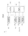
- Fig. 4 is a block diagram explaining an example structure of the transmission apparatus 15.
- the transmission apparatus 15 comprises a shift switch 19a, a clutch sensor 19b, a shift actuator position sensor 19c, and a shift cam position sensor 19d. These sensors are connected to the control device 10.
- the shift switch 19a is a switch operated by a passenger, and outputs a shift instruction (a shift up instruction to advance the shift step or a shift down instruction to reverse the shift step) to the control device 10.
- the shift switch 19a includes a shift up switch and a shift down switch.
- the clutch sensor 19b comprises, e.g., a potentiometer for outputting a signal according to the position of a pressure plate (not shown) included in the clutch 40.
- the control device 10 can determine a state (fully engaged state, half-engaged state, release state) of the clutch 40, based on the signal output from the clutch sensor 19b.
- the shift actuator position sensor 19c comprises, e.g., a potentiometer for outputting a voltage signal according to the rotation angle of the shift actuator 38.
- the control device 10 can determine the current position and moving speed of the movable gear 7 and the current shift step, based on the signal output from the shift actuator position sensor 19c.
- the shift cam position sensor 19d comprises, e.g., a potentiometer for outputting a voltage signal according to the rotation angle of the shift cam 33.
- the control device 10 can determine the current position and moving speed of the movable gear 7 and the current shift step, based on the signal output from the shift cam position sensor 19d.
- the control device 10 comprises a CPU (Central Processing Unit) and a memory such as a ROM (Read Only Memory) and a RAM (Random Access Memory).
- a CPU Central Processing Unit
- a memory such as a ROM (Read Only Memory) and a RAM (Random Access Memory).
- Fig. 5 is a block diagram showing an example functional structure of the control device 10.
- the control device 10 comprises a shift instruction receiving unit 101, a movable gear control unit 102, a clutch control unit 103, a gear position information obtaining unit 104, an engaged stage determining unit 105, a gear speed information obtaining unit 106, and a clutch position information obtaining unit 107.
- the respective units included in the control device 10 are realized by executing a program stored in the memory by the CPU of the control device 10.
- the shift instruction receiving unit 101 receives a shift instruction output from the shift switch 19a, and outputs the received shift instruction to the movable gear control unit 102 and the clutch control unit 103.
- the movable gear control unit 102 drives the shift actuator 38 to switch the shift step set by the transmission mechanism 30 to a step according to the shift instruction.
- the movable gear control unit 102 includes a pulse width modulator for converting an input signal into a pulse width modulation (PWM) signal, and applies PWM control to the shift actuator 38.
- the pulse width modulator generates a PWM signal having a duty ratio corresponding to an output target value of the shift actuator 38.
- the movable gear control unit 102 may supply a voltage corresponding to the output target value to the shift actuator 38.
- the clutch control unit 103 Upon receipt of the shift instruction from the shift instruction receiving unit 101, the clutch control unit 103 drives the clutch actuator 49 to leave the clutch 40 in a release state so that the transmission mechanism 30 can set a clutch step.
- the clutch control unit 103 as well applies PWM control to the clutch actuator 49.
- the gear position information obtaining unit 104 obtains position information on the movable gear 7, based on an output signal from the shift cam position sensor 19d, and outputs the obtained position information to the movable gear control unit 102 and the engaged stage determining unit 105.
- the gear position information obtaining unit 104 may obtain position information on the movable gear 7, based on the output signal from the shift actuator position sensor 19c.
- the engaged stage determining unit 105 determines, based on the position information on the movable gear 7, at which of the dog disengaged stage, the dog bumping stage, and the dog engaged stage the movable gear 7 currently is. At which step the movable gear 7 currently is is determined based on, e.g., a relationship between the respective thresholds corresponding to the dog disengaged stage, the dog bumping stage, and the dog engaged stage, and a signal value of the shift actuator position sensor 19c or the shift cam position sensor 19d.
- the gear speed information obtaining unit 106 obtains speed information on the movable gear 7, based on the output signal from the shift cam position sensor 19d, and outputs the obtained speed information to the movable gear control unit 102.
- the gear speed information obtaining unit 106 may obtain speed information on the movable gear 7, based on the output signal from the shift actuator position sensor 19c.
- the clutch position information obtaining unit 107 obtains information indicating the state (a fully engaged state, a half-engaged state, a release state) of the clutch 40, based on the output signal from the clutch sensor 19b, and outputs the obtained information to the clutch control unit 103.
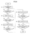
- Fig. 6 is a flowchart of an example operation of the control device 10.
- Fig. 7 is a timing chart of an example operation of the control device 10. Specifically, Fig. 7 shows a part corresponding to the process at S1 to S6 shown in Fig. 6 .
- the upper line (a) relates to a rotation angle of the shift actuator 38.
- the middle line (b) relates to a rotation angle of the shift cam 33.
- the abscissa indicates time, while the ordinate indicates a rotation angle.
- the respective rotation angles of the shift actuator 38 and the shift cam 33 change from the position L1 at the dog disengaged stage (see Fig. 3A ) via the position L2 at the dog bumping stage (see Fig. 3B ) to the position L3 at the dog engaged stage (see Fig. 3B ) .
- the lower line (c) indicates a duty ratio of a PWM signal to be given to the shift actuator 38.
- the abscissa indicates time, while the ordinate indicates a duty ratio. The duty ratio varies between -100% and +100%.
- the movable gear control unit 102 begins dog disengaging control (S1).
- the movable gear control unit 102 outputs a positive voltage to the shift actuator 38.
- a positive voltage here refers to a voltage for applying a force toward the second stationary gear 6 to the movable gear 7.
- the movable gear control unit 102 outputs a PWM signal having a duty ratio according to the difference between a target position and the current position of the movable gear 7, the target position being the position L2 at the dog bumping stage. Therefore, a positive PWM signal having the maximum duty ratio (e.g., 100%) is output at the initial stage in the dog disengaging control.
- a PWM signal may always have the maximum duty ratio during a period with the dog disengaging control, or alternatively, the maximum duty ratio may gradually decrease after elapse of a predetermined period of time.
- the engaged stage determining unit 105 monitors completion of the dog disengaged stage (S2), and upon determination of completion of the dog disengaged stage (S2: YES), notifies the movable gear control unit 102 of the completion. For example, the engaged stage determining unit 105 may determine completion of the dog disengaged stage when the shift cam 33 reaches a predetermined dog disengagement determination position Ld.
- the engaged stage determining unit 105 may measure a period of time elapsed after the start of a shift operation, and determine completion of the dog disengaged stage when a predetermined dog disengagement determination period of time elapses after the start of the shift operation.
- a period of time having elapsed after the start of a shift operation corresponds to a period of time with a force toward the second stationary gear 6 kept applied to the movable gear 7.
- the movable gear control unit 102 Upon receipt of the notice of completion of the dog disengaged stage from the engaged stage determining unit 105, the movable gear control unit 102 carries out brake control (S3) . In the brake control, the movable gear control unit 102 outputs a negative voltage to the shift actuator 38.
- a negative voltage here refers to a voltage for applying a force directed opposite from a direction toward the second stationary gear 6 (hereinafter referred to as a brake force) to the movable gear 7.
- applying a brake force to the movable gear 7 after completion of the dog disengaged stage as described above can decrease the moving speed of the movable gear 7 before the movable gear 7 reaches the position L2 at the dog bumping stage, to thereby modify the impact in bumping between the dog 74 of the movable gear 7 and the dog 64 of the second stationary gear 6.
- At least one of the duty radio (a brake duty ratio) of a negative PWM signal in the brake control and the effective period of time t (brake period) of the brake control may be determined based on, e.g., speed information on the movable gear 7 supplied from the gear speed information obtaining unit 106. That is, by increasing the brake duty d with respect to a higher moving speed of the movable gear 7 moving toward the second stationary gear 6 (that is, a larger brake force is to be applied to the movable gear 7), it is possible to sufficiently reduce the moving speed of the movable gear 7. Further, it is also possible to make uniform the impact in bumping between the dog 74 of the movable gear 7 and the dog 64 of the second stationary gear 6. Note that the identical effect can be obtained with a longer braking period of time t.
- the movable gear control unit 102 After elapse of a predetermined period of time after the start of the brake control (S4: YES), the movable gear control unit 102 ends the brake control, and then begins dog pushing control (S5) .
- the movable gear control unit 102 outputs a positive voltage to the shift actuator 38 to accelerate shifting to the dog engaged stage.
- the movable gear control unit 102 outputs a positive PWM signal having a duty ratio smaller than the maximum value.
- the engaged stage determining unit 105 monitors completion of the dog engaged stage (S6), and upon determination of completion of the dog engaged stage (S6: YES), notifies the clutch control unit 103 of the completion. For example, the engaged stage determining unit 105 may determine completion of the dog engaged stage when the shift cam 33 reaches the predetermined position L3 at the dog engaged stage.
- the clutch control unit 103 Upon receipt of the notice of completion of the dog engaged stage from the engaged stage determining unit 105, the clutch control unit 103 carries out a half-clutch control to reduce shock in shifting (S7). That is, the clutch control unit 103 keeps outputting a signal for leaving the clutch 40 in a half-clutch state to the clutch actuator 49.
- the movable gear control unit 102 After the half-clutch control begins and the rotation speed difference of the clutch 40 becomes closer to 0 (S8: YES), the movable gear control unit 102 begins shift return control to return the rotation angle of the shift actuator 38 to the original position. In addition, the clutch control unit 103 leaves the clutch 40 in a fully engaged state. After the shift return control ends and the clutch 40 comes to be in the fully engaged state (S10: YES), the shifting ends.
- the position information obtaining unit 104 obtains position information indicating the position of the movable gear 7, and the engaged stage determining unit 105 determines, based on the position information, whether or not the engagement between the dogs 52, 72 of the first stationary gear 5 and of the movable gear 7 is released. Then, upon determination that the engagement between the dogs 52, 72 of the first stationary gear 5 and of the movable gear 7 is released, the movable gear control unit 102 applies a brake force to the movable gear 7.
- This arrangement makes it easier to set a time for applying a brake force to the movable gear 7 to a time before the dogs 74, 64 of the movable gear 7 and of the second stationary gear 6 contact each other.
- the position information obtaining unit 104 obtains information on the rotation angle of the shift actuator 38 as the position information. This makes it possible to obtain position information on the movable gear 7 without providing a structure for directly determining the position of the movable gear 7.
- the position information obtaining unit 104 obtains information on the rotation angle of the shift cam 33 as the position information. This makes it possible to obtain position information on the movable gear 7 without providing a structure for directly determining the position of the movable gear 7.
- the movable gear control unit 102 begins applying a force in an opposite direction to the movable gear 7 after elapse of a predetermined period of time after the movable gear 7 starts moving toward the second speed. This makes it possible, without using the position information on the movable gear 7, to apply a brake force to the movable gear 7 before the dogs 74, 64 of the movable gear 7 and of the second stationary gear 6 contact each other.
- the gear speed information obtaining unit 106 obtains speed information indicating the moving speed of the movable gear 7, and the movable gear control unit 102 determines the magnitude of a brake force according to the moving speed of the movable gear 7. This makes it possible to sufficiently reduce the moving speed of the movable gear 7 before the dogs 74, 64 of the movable gear 7 and of the second stationary gear 6 contact each other even though the moving speed of the movable gear 7 is high.
- the gear speed information obtaining unit 106 obtains speed information indicating the moving speed of the movable gear 7, and the movable gear control unit 102 determines according to the moving speed of the movable gear 7, the duration of a brake force kept applied to the movable gear 7.
- Fig. 8 is a timing chart for an example operation according to a first modified example. In the following, a point identical to that in the above described example operation will not be described in detail.
- the movable gear control unit 102 upon determination of completion of the dog disengaged stage and thereafter elapse of a predetermined waiting period of time t2, the movable gear control unit 102 begins brake control.
- the waiting period of time t2 is set within a range with the movable gear 7 not reaching a position at the dog bumping stage.
- Fig. 9 is a block diagram showing an example functional structure of a second modified example.
- Fig. 10 is a timing chart for an example operation according to the second modified example. In the following, a point identical to that in the above described operation example will not be described in detail.
- the control device 10 has a gear target position calculation unit 108 for calculating a target position of the movable gear 7.
- the movable gear control unit 102 carries out feedback control for changing an output from the shift actuator 38 according to the difference between a target position of the movable gear 7 output from the gear target position calculation unit 108 and the current position of the movable gear 7 output from the gear position information obtaining unit 104.
- the feedback control is e.g., PID control, and that the target position of the movable gear 7 is set such that a brake force is applied to the movable gear 7 before the movable gear 7 reaches the position L2 at the dog bumping stage.
- a brake force is applied to the movable gear 7 when the movable gear 7 approaches the position L2 at the dog bumping stage.
- the moving speed of the movable gear 7 can be decreased before the dogs 74, 64 of the movable gear 7 and of the second stationary gear 6 contact each other.
- the gear target position calculation unit 108 may update the target position of the movable gear 7 to the position L3 or a nearby position at the dog engaged stage after the movable gear 7 reaches the position L2 at the dog bumping stage. This makes it possible to generate a pushing force after the movable gear 7 reaches the position L2 at the dog engaged stage to thereby accelerate completion of the dog engaged stage.
Abstract
Description
- The present invention relates to a transmission apparatus and a saddle-riding type vehicle, and in particular to movement control of a movable gear included in a dog clutch transmission mechanism.
- Conventionally, two-wheeled motor vehicles having a dog clutch transmission mechanism, for performing a shift operation using an actuator have been known.
- A dog clutch transmission mechanism has a stationary gear capable of relative rotation relative to a shaft but incapable of movement in the shaft direction, and a movable gear incapable of relative rotation relative to a shaft but capable of movement in the shaft direction, and mutually engageable dogs are formed on the respective lateral surfaces of the movable gear and the stationary gear. In such a transmission mechanism, in shifting, engagement between the dog of a stationary gear for a speed before shifting (hereinafter referred to as a pre-shifting stationary gear) and the dog of a movable gear is released (a dog disengaged stage) . Thereafter, the dog of the above mentioned or different movable gear is engaged with the dog of a stationary gear for a speed after shifting (hereinafter referred to as a post-shifting stationary gear) (a dog engaged stage). In the above, the dog of the movable gear may bump into the dog of the post-shifting stationary gear (a dog bumping stage) before the dog engaged stage.
- Patent Document 1: Japanese Patent Laid-open Publication No.
Hei 11-148551 - Patent Document 1 describes that a sleeve is moved at a high speed to realize prompt shifting, and that braking is applied to a drive motor when the sleeve reaches a dowel-in position to thereby modify the impact in bumping between a shift spindle and a stopper. According to Patent Document 1, "dowel-in" is defined as that a dowel of the sleeve is fit into a slot formed on the gear, and the dog bumping stage mentioned above corresponds to a stage in which the dowel of the sleeve bumps into a part other than the slot on the gear. In view of the above, braking when the sleeve reaches a dowel-in position means braking after the dog bumping stage. That is, the dowel of the sleeve has already bumped into the part other than the slot on the gear at a high speed. In bumping, a friction force is caused between the dowel of the sleeve and the part other than the slot on the gear, and the friction force hinders relative movement of the two. This results in delay in engagement between the dowel and the slot, as a result of which prompt shifting may not be realized. This problem becomes more remarkable as the moving speed of the sleeve is increased for the purpose of realizing prompt shifting.
- Further, Patent Document 1 describes that re-pushing control is performed when shift change is not duly performed. In the re-pushing control, a sleeve pushing torque is temporarily weakened, and then increased so that the sleeve is pushed again with a stronger torque. Note that shift change not being duly performed refers to the sleeve not reaching the dowel-in position, with the dowel of the sleeve left bumping on the part other than the slot on the gear. According to Patent Document 1, the dowel of the sleeve has already bumped into the part other than the slot on the gear at a high speed. Change in strength of the pushing torque after such high speed bumping will not contribute to prompt shifting as the change is applied after the relative speed of the two have already dropped.
- Moreover, such a problem becomes more remarkable as a force to be applied to a movable gear is increased to release the engagement at the dog disengaged stage. That is, a large load is kept being applied to the actuator that drives the movable gear until the engagement between the dog of the pre-shifting stationary gear and that of the movable gear is released, and at the moment when the engagement is released, the load turns to be a force pushing the movable gear toward the post-shifting stationary gear. Consequently, the dog of the movable gear fiercely bumps into the dog of the post-shifting stationary gear. In this case, remarkable delay is caused in shifting from the dog bumping stage to the dog engaged stage. Regarding this point, Patent Document 1 does not include a description on the dog disengaged stage. In this view, it is considered that the speed at which the dowel of the sleeve bumps into the part other than the slot is originally not so high that delays engagement.
- The present invention has been conceived in view of the above described problem, and aims to provide a transmission apparatus and a saddle-riding type vehicle capable of prompt shifting and modification of the impact in bumping between dogs.
- In order to solve the above described object, according to one aspect of the present invention, there is provided a transmission apparatus comprising a dog clutch transmission mechanism, an actuator, and a control device for driving the actuator. The transmission mechanism includes a first stationary gear capable of relative rotation relative to a shaft and incapable of movement in a shaft direction, a second stationary gear capable of relative rotation relative to the shaft and incapable of movement in the shaft direction, and a movable gear provided on the shaft between the first stationary gear and the second stationary gear and incapable of relative rotation relative to the shaft and capable of movement in the shaft direction. A dog for being engaged with a dog formed on a lateral surface of the first stationary gear to transmit rotation of the shaft to the first stationary gear is formed on one lateral surface of the movable gear. A dog for being engaged with a dog formed on a lateral surface of the second stationary gear to transmit the rotation of the shaft to the second stationary gear is formed on another lateral surface of the movable gear. The actuator moves the movable gear in the shaft direction. When the movable gear moves from a state in which the dog thereof is engaged with the dog of the first stationary gear toward the second stationary gear, the control device applies a force directed opposite from a direction toward the second stationary gear to the movable gear after the engagement between the dog of the first stationary gear and the dog of the movable gear is released, until the movable gear reaches a position where the dog of the movable gear contacts the dog of the second stationary gear.
- According to another aspect of the present invention, there is provided a transmission apparatus comprising a dog clutch transmission mechanism, an actuator, and a control device for driving the actuator. The transmission mechanism includes a first stationary gear, a first movable gear, a second stationary gear, a second movable gear, and a shift cam. The first stationary gear is capable of relative rotation relative to a shaft and incapable of movement in the shaft direction. The first movable gear is provided to the shaft where the first stationary gear is provided, and incapable of relative rotation relative to the shaft and capable of movement in the shaft direction. The second stationary gear is capable of relative rotation relative to the shaft where the first stationary gear is provided or a different shaft and incapable of movement in the shaft direction. The second movable gear is provided to the shaft where the second stationary gear is provided, and incapable of relative rotation relative to the shaft and capable of movement in the shaft direction. The shift cam moves the first movable gear and the second movable gear in the shaft direction. A dog for being engaged with a dog formed on a lateral surface of the first stationary gear to transmit rotation of the shaft where the first stationary gear is provided to the first stationary gear is formed on a lateral surface of the first movable gear that is opposed to the first stationary gear. A dog for being engaged with a dog formed on a lateral surface of the second stationary gear to transmit rotation of the shaft where the second stationary gear is provided to the second stationary gear is formed on a lateral surface of the second movable gear that is opposed to the second stationary gear. The actuator drives the shift cam. When the second movable gear moves toward the second stationary gear from a state in which the dog of the first stationary gear being engaged with the dog of the first movable gear, the control device applies a force directed opposite from the direction toward the second stationary gear to the second movable gear after the engagement between the dog of the first stationary gear and the dog of the first movable gear is released, until the second movable gear reaches a position where the dog of the second movable gear contacts the dog of the second stationary gear.
- According to a further aspect of the present invention, there is provided a saddle-riding type vehicle having the above described transmission apparatus. A saddle-riding type vehicle is a vehicle in which a user straddles a seat to sit thereon, being, e.g., a two-wheeled motor vehicle (including a scooter), an all-terrain vehicle, a snowmobile, and so forth.
- According to the present invention, as a force directed opposite from the direction toward the second stationary gear is applied to a movable gear before the dog of the movable gear contacts the dog of the second stationary gear, it is possible to modify bumping between the dogs and also to realize prompt shifting.
-
Fig. 1 is a side view of a two-wheeled motor vehicle; -
Fig. 2 is a schematic diagram of a torque transmission path; -
Fig. 3A is a diagram explaining a dog disengaged stage; -
Fig. 3B is a diagram explaining a dog bumping stage; -
Fig. 3C is a diagram explaining a dog engaged stage; -
Fig. 4 is a block diagram showing an example structure of a transmission apparatus; -
Fig. 5 is a block diagram showing an example functional structure of a control device; -
Fig. 6 is a flowchart of an example operation of the control device; -
Fig. 7 is a timing chart of an example operation of the control device; -
Fig. 8 is a timing chart of an example operation of the control device; -
Fig. 9 is a block diagram showing an example functional structure of the control device; and -
Fig. 10 is a timing chart of an example operation of the control device. - An embodiment of a transmission apparatus and a saddle-riding type vehicle according to an embodiment of the present invention will be described referring to the accompanying drawings.
-
Fig. 1 is a side view of a two-wheeled motor vehicle 1. The two-wheeled motor vehicle 1 is one example of a saddle-riding type vehicle according to the present invention, and has anengine unit 11. Afront wheel 2 provided in the forward direction of theengine unit 11 is supported by the lower end of afront fork 4. A steeringshaft 81 rotatably supported at the forwardmost part of a vehicle frame (not shown) is connected to an upper part of thefront fort 4. A steering 83 is mounted on an upper part of the steeringshaft 81. The steering 83, thefront fork 4, and thefront wheel 2 are provided so as to integrally rotate in the left-right direction with the steeringshaft 81 as the center. Aseat 9 on which a passenger can straddle to sit thereon is mounted behind thesteering 83. Arear wheel 3 is provided to the rear of theengine unit 11. A torque output from theengine unit 11 is transmitted to therear wheel 3 through a torque transmitting member (not shown), such as a chain, a belt, and a shaft. Acontrol device 10 is provided to the two-wheeled motor vehicle 1. Theengine unit 11 and thecontrol device 10 constitute atransmission apparatus 15 according to one example of the present invention. -
Fig. 2 is a diagram schematically showing a torque transmission path. Theengine unit 11 comprises a clutch 40, a dogclutch transmission mechanism 30, and ashift actuator 38. The clutch 40 has a drivingmember 41 capable of relative rotation relative to theinput shaft 31 of thetransmission mechanism 30. The drivingmember 41 of the clutch 40 has aprimary gear 41a, which is engaged with aprimary gear 21a mounted on a crank shaft (not shown) . The clutch 40 has a followingmember 42 incapable of relative rotation relative to theinput shaft 31 of thetransmission mechanism 30. The clutch 40 is, e. g. , a single-plate or multi-plate friction clutch. The drivingmember 41 and the followingmember 42 are pressed to each other in the shaft direction so that torque is transmitted between the twomembers member 41 may be, e.g., a friction disk, while the followingmember 42 may be, e.g., a clutch disk. - The clutch 40 has a
clutch actuator 49 for changing the state of engagement between the drivingmember 41 and the followingmember 42 according to an instruction from thecontrol device 10. Theclutch actuator 49 comprises, e.g., an electric motor. A driving force of the electric motor is transmitted to either one of the drivingmember 41 and the followingmember 42 by means of hydraulic pressure or a rod to press or separate the drivingmember 41 and the followingmember 42 with respect to each other. - The
transmission mechanism 30 comprises theinput shaft 31 having a plurality ofgears 1i to 6i mounted thereon, anoutput shaft 32 having a plurality ofgears 1h to 6h mounted thereon to be engaged with thesegears 1i to 6i, and ashift cam 33 having ashift fork 36. Theinput shaft 31 is connected to the followingmember 42 of the clutch 40, while theoutput shaft 32 is connected to the wheel shaft of therear wheel 3 via a torque transmitting member, such as a chain, a belt, and a shaft. Thegear 1i is engaged with thegear 1h with a shift reduction rate corresponding to the first speed. Thegear 2i is engaged with thegear 2h with a shift reduction rate corresponding to the second speed. Thegear 3i is engaged with thegear 3h with a shift reduction rate corresponding to the third speed. Thegear 4i is engaged with thegear 4h with a shift reduction rate corresponding to the fourth speed. Thegear 5i is engaged with thegear 5h with a shift reduction rate corresponding to the fifth speed. Thegear 6i is engaged with thegear 6h, with the shift reduction rate thereof gears corresponding to the sixth speed. - Of each gear pair corresponding to a respective shift step, one gear is capable of relative rotation relative to the shaft where the gear is provided, while the other gear is engaged spline with the shaft where the gear is provided and thus incapable of relative rotation relative to that shaft. In this embodiment, the
gears 1i to 4i are incapable of relative rotation relative to theinput shaft 31, while thegears 1h to 4h are capable of relative rotation relative to theoutput shaft 32. The gears 5i, 6i are capable of relative rotation relative to theinput shaft 31, while thegears output shaft 32. Accordingly, in a neutral condition with no particular shift step set, thegear parts 1i-1h to 4i-4h follow theinput shaft 31, while the gear pairs 5i-5h, 6i-6h follow theoutput shaft 32. Note that thegears gear 34i) . - The gear capable of relative rotation relative to the shaft is incapable of movement in the shaft direction of the shaft where the gear is provided, and is thus referred to as a stationary gear. Meanwhile, some of the gears incapable of relative rotation relative to the shaft are capable of movement in the shaft direction of the shaft where the gear is provided, and is thus referred to as a movable gear. A movable gear can move between two stationary gears. In this embodiment, the
gears gears gear 34i can move between thegears input shaft 31. Thegear 5h can move between thegears output shaft 32. Thegear 6h can move between thegears output shaft 32. Eachgear engagement slot 35 formed thereon, in which ashift fork 36 provided to theshift cam 33 is fit. - The movable gear is engageable with the stationary gear by means of a dog clutch. In this embodiment, a
dog 39 is formed on each of the both lateral sides of eachgear dog 39 is formed on a lateral side of eachgear dogs 39 engaged with each other, a torque from theinput shaft 31 is transmitted to theoutput shaft 32. For example, with thedog 39 of thegear 34i engaged with thedog 39 of thegear 5i, rotation of theinput shaft 31 is transmitted from thegear 34i via thedogs 39 to thegear 5i, which in turn rotates integrally with theinput shaft 31. - A plurality of
cam slots 33d are formed on theshift cam 33, of which positions in the shaft direction vary depending on the rotation angle. Theshift fork 36 is fit in therespective cam slot 33d. Theshift cam 33 is connected to theshift actuator 38 via theshift rod 37, and theshift actuator 38 generates a drive force for rotating theshift cam 33. Theshift actuator 38 comprises, e.g., an electric motor. With theshift actuator 38 rotating, the rotation is transmitted via theshift rod 37 to theshift cam 33, which in turn rotates. The rotation of theshift cam 33 is converted into movement in the shaft direction of theshift fork 36 fit in thecam slot 33d. As a result, thegears gears shift actuator 38. - In shifting, a state in which a movable gear is engaged with a stationary gear for a speed before the shifting (pre-shifting stationary gear) is switched to a state in which a movable gear is engaged with a stationary gear for a speed after the shifting (post-shifting stationary gear). According to a first shifting aspect, a movable gear engaged with a pre-shifting stationary gear is the same as a movable gear engaged with a post-shifting stationary gear. For example, in shifting from the second speed to the third speed, the
gear 6h moves from a state in which thegear 6h is engaged with thegear 2h toward thegear 3h and then is engaged with thegear 3h. In switching from the fifth speed to the sixth speed, thegear 34i moves from a state in which thegear 34i is engaged with thegear 5i toward thegear 6i and then is engaged with thegear 6i. - Meanwhile, according to a second shifting aspect, a movable gear engaged with a pre-shifting stationary gear is different from a movable gear engaged with a post-shifting stationary gear. For example, in shifting from the first speed to the second speed, the
gear 5h moves from a state in which thegear 6h is engaged with thegear 1h so as to depart from thegear 1h, and thegear 6h then moves toward thegear 2h and is engaged with thegear 2h. In shifting from the third speed to the forth gear, thegear 6h moves from a state in which thegear 6h is engaged with thegear 3h so as to depart from thegear 3h, and thegear 5h then moves toward thegear 4h and is engaged with thegear 4h. In shifting from the fourth speed to the fifth speed, thegear 5h moves from a state in which thegear 5h is engaged with thegear 4h so as to depart from thegear 4h, and thegear 34i then moves toward thegear 5i and is engaged with thegear 5i. - In switching the engagement between a movable gear and a stationary gear, as described above, the movable gear sequentially experiences three stages (a dog disengaged stage, a dog bumping stage, a dog engaged stage) to be described below.
Fig. 3A is a diagram showing a dog disengaged stage;Fig. 3B is a diagram showing a dog bumping stage; andFig. 3C is a diagram showing a dog engaged stage. These diagrams are schematic diagrams with a gear rotation direction in the up-down direction thereof. An arrow in these diagrams indicates the moving direction of themovable gear 7 moving toward the secondstationary gear 6. Themovable gear 7 corresponds to therespective gears Fig. 2 , and the firststationary gear 5 and the secondstationary gear 6 correspond to the respective gears 5i, 6i, 1h to 4h inFig. 2 . The firststationary gear 5 corresponds to a pre-shifting stationary gear, while the secondstationary gear 6 corresponds to a post-shifting stationary gear. - A
dog 72 is formed on a lateral surface of themovable gear 7 that faces the firststationary gear 5, projecting toward the firststationary gear 5, and aconcave insertion part 77 is formed adjacent to thedog 72 in the gear rotation direction. Note that a convex and a concave formed by theconvex dog 72 and theconcave insertion part 77, respectively, have relative relationship, and specifically, a part without theconvex dog 72 is referred to as theconcave insertion part 77, and a part without theconcave insertion part 77 is referred to as theconvex dog 72. Similarly, adog 52 is formed on a lateral surface of the firststationary gear 5 that faces themovable gear 7, projecting toward themovable gear 7, and aconcave insertion part 57 is formed adjacent to thedog 52 in the gear rotation direction. When thedog 72 of themovable gear 7 is inserted into theinsertion part 57 of the firststationary gear 5 and thedog 52 of the firststationary gear 5 is inserted into theinsertion part 77 of themovable gear 7, thedog 72 of themovable gear 7 is engaged with thedog 52 of the firststationary gear 5. With the above, a torque from one of themovable gear 7 and the firststationary gear 5 is transmitted to the other via thedogs - A
dog 74 is formed on a lateral surface of themovable gear 7 that faces the secondstationary gear 6, projecting toward the secondstationary gear 6, and aconcave insertion part 79 is formed adjacent to thedog 74 in the gear rotation direction. Note that a convex and a concave formed by theconvex dog 74 and theconcave insertion part 79, respectively, have relative relationship, and specifically, a part without theconvex dog 74 is referred to as theconcave insertion part 79, and a part without theconcave insertion part 79 is referred to as theconvex dog 74. Similarly, adog 64 is formed on a lateral surface of the secondstationary gear 6 that faces themovable gear 7, projecting toward themovable gear 7, and aconcave insertion part 69 is formed adjacent to thedog 64 in the gear rotation direction. When thedog 74 of themovable gear 7 is inserted into theinsertion part 69 of the secondstationary gear 6 and thedog 64 of the secondstationary gear 6 is inserted into theinsertion part 79 of themovable gear 7, thedog 74 of themovable gear 7 is engaged with thedog 64 of the secondstationary gear 6. With the above, a torque from one of themovable gear 7 and the secondstationary gear 6 is transmitted to the other via thedogs - At the dog disengaged stage shown in
Fig. 3A , the engagement between thedog 72 of themovable gear 7 and thedog 52 of the firststationary gear 5 is released. Specifically, when a drive force of theshift actuator 38 is transmitted from theshift cam 33 to themovable gear 7, and themovable gear 7 thus starts moving toward the secondstationary gear 6, thedog 72 of themovable gear 7 comes off theinsertion part 57 of the firststationary gear 5, and thedog 52 of the firststationary gear 5 comes off theinsertion part 77 of themovable gear 7. In the above, as thedog 72 of themovable gear 7 and thedog 52 of the firststationary gear 5 are forced to contact each other by high pressure, separation of themovable gear 7 from thestationary gear 5 requires an increased output from theshift actuator 38 to apply a stronger force to themovable gear 7. - At the dog bumping stage shown in
Fig. 3B , thedog 74 of themovable gear 7 bumps into thedog 64 of the secondstationary gear 6. That is, at the dog bumping stage, thedog 74 of themovable gear 7 bumps into a part other than theinsertion part 69 on the secondstationary gear 6. In the above, when the moving speed of themovable gear 7 is high, the relative rotation speed of themovable gear 7 and the secondstationary gear 6 drops due to the bump between thedog 74 of themovable gear 7 and thedog 64 of the secondstationary gear 6. This may cause delay in shifting to the dog engaged stage. Therefore, preferably, the moving speed of themovable gear 7 is decreased to modify the impact in bumping into the secondstationary gear 6. - However, when a strong force is applied to the
movable gear 7 to release the engagement between themovable gear 7 and the firststationary gear 5 at the dog disengaged stage, themovable gear 7 is pushed at a high speed by the force at the moment when the engagement is released, and consequently highly likely fiercely bumps into the secondstationary gear 6. If this occurs, remarkable delay in shifting to the dog engaged stage is resulted. - At the dog engaged stage shown in
Fig. 3C , thedog 74 of themovable gear 7 is engaged with thedog 64 of the secondstationary gear 6. That is, thedog 74 of themovable gear 7 is inserted into theinsertion part 69 of the secondstationary gear 6, and thedog 64 of the secondstationary gear 6 is inserted into theinsertion part 79 of themovable gear 7, so that thedog 74 of themovable gear 7 and thedog 64 of the secondstationary gear 6 are brought to contact each other in the gear rotation direction. In the above, preferably, a pushing force is applied to themovable gear 7 to assist insertion of thedogs - Note that the dog disengaged stage may directly shift to the dog engaged stage without intervention of the dog bumping stage. This occurs when the
dog 74 of themovable gear 7 is inserted directly into theinsertion part 69 without bumping into thedog 64 of the secondstationary gear 6. - The above described description on
Figs. 3A to 3C is applicable also to a case according to the second shifting aspect in which a movable gear engaged with a pre-shifting stationary gear differs from a movable gear engaged with a post-shifting stationary gear. That is, when a strong torque is applied to the shift cam 33 (seeFig. 2 ) in order to release engagement between the pre-shifting stationary gear and the first movable gear at the dog disengaged stage, theshift cam 33 abruptly starts rotating at the moment when the engagement is released. In the above, the moving speeds of not only the first movable gear but also all movable gears connected to theshift cam 33 increase, and consequently, the second movable gear fiercely bumps into the post-shifting stationary gear. Therefore, the following description on control will be similarly applied to the second shifting aspect. -
Fig. 4 is a block diagram explaining an example structure of thetransmission apparatus 15. Thetransmission apparatus 15 comprises ashift switch 19a, aclutch sensor 19b, a shiftactuator position sensor 19c, and a shiftcam position sensor 19d. These sensors are connected to thecontrol device 10. - The
shift switch 19a is a switch operated by a passenger, and outputs a shift instruction (a shift up instruction to advance the shift step or a shift down instruction to reverse the shift step) to thecontrol device 10. Theshift switch 19a includes a shift up switch and a shift down switch. - The
clutch sensor 19b comprises, e.g., a potentiometer for outputting a signal according to the position of a pressure plate (not shown) included in the clutch 40. Thecontrol device 10 can determine a state (fully engaged state, half-engaged state, release state) of the clutch 40, based on the signal output from theclutch sensor 19b. - The shift
actuator position sensor 19c comprises, e.g., a potentiometer for outputting a voltage signal according to the rotation angle of theshift actuator 38. Thecontrol device 10 can determine the current position and moving speed of themovable gear 7 and the current shift step, based on the signal output from the shiftactuator position sensor 19c. - The shift
cam position sensor 19d comprises, e.g., a potentiometer for outputting a voltage signal according to the rotation angle of theshift cam 33. Thecontrol device 10 can determine the current position and moving speed of themovable gear 7 and the current shift step, based on the signal output from the shiftcam position sensor 19d. - The
control device 10 comprises a CPU (Central Processing Unit) and a memory such as a ROM (Read Only Memory) and a RAM (Random Access Memory). -
Fig. 5 is a block diagram showing an example functional structure of thecontrol device 10. Thecontrol device 10 comprises a shiftinstruction receiving unit 101, a movablegear control unit 102, aclutch control unit 103, a gear positioninformation obtaining unit 104, an engagedstage determining unit 105, a gear speedinformation obtaining unit 106, and a clutch positioninformation obtaining unit 107. The respective units included in thecontrol device 10 are realized by executing a program stored in the memory by the CPU of thecontrol device 10. - The shift
instruction receiving unit 101 receives a shift instruction output from theshift switch 19a, and outputs the received shift instruction to the movablegear control unit 102 and theclutch control unit 103. - Upon receipt of the shift instruction from the shift
instruction receiving unit 101, the movablegear control unit 102 drives theshift actuator 38 to switch the shift step set by thetransmission mechanism 30 to a step according to the shift instruction. Specifically, the movablegear control unit 102 includes a pulse width modulator for converting an input signal into a pulse width modulation (PWM) signal, and applies PWM control to theshift actuator 38. The pulse width modulator generates a PWM signal having a duty ratio corresponding to an output target value of theshift actuator 38. Alternatively, not being limited to the above, the movablegear control unit 102 may supply a voltage corresponding to the output target value to theshift actuator 38. - Upon receipt of the shift instruction from the shift
instruction receiving unit 101, theclutch control unit 103 drives theclutch actuator 49 to leave the clutch 40 in a release state so that thetransmission mechanism 30 can set a clutch step. Theclutch control unit 103 as well applies PWM control to theclutch actuator 49. - The gear position
information obtaining unit 104 obtains position information on themovable gear 7, based on an output signal from the shiftcam position sensor 19d, and outputs the obtained position information to the movablegear control unit 102 and the engagedstage determining unit 105. Alternatively, not being limited to the above, the gear positioninformation obtaining unit 104 may obtain position information on themovable gear 7, based on the output signal from the shiftactuator position sensor 19c. - The engaged
stage determining unit 105 determines, based on the position information on themovable gear 7, at which of the dog disengaged stage, the dog bumping stage, and the dog engaged stage themovable gear 7 currently is. At which step themovable gear 7 currently is is determined based on, e.g., a relationship between the respective thresholds corresponding to the dog disengaged stage, the dog bumping stage, and the dog engaged stage, and a signal value of the shiftactuator position sensor 19c or the shiftcam position sensor 19d. - The gear speed
information obtaining unit 106 obtains speed information on themovable gear 7, based on the output signal from the shiftcam position sensor 19d, and outputs the obtained speed information to the movablegear control unit 102. Alternatively, not being limited to the above, the gear speedinformation obtaining unit 106 may obtain speed information on themovable gear 7, based on the output signal from the shiftactuator position sensor 19c. - The clutch position
information obtaining unit 107 obtains information indicating the state (a fully engaged state, a half-engaged state, a release state) of the clutch 40, based on the output signal from theclutch sensor 19b, and outputs the obtained information to theclutch control unit 103. -
Fig. 6 is a flowchart of an example operation of thecontrol device 10.Fig. 7 is a timing chart of an example operation of thecontrol device 10. Specifically,Fig. 7 shows a part corresponding to the process at S1 to S6 shown inFig. 6 . - In
Fig. 7 , the upper line (a) relates to a rotation angle of theshift actuator 38. The middle line (b) relates to a rotation angle of theshift cam 33. As to the lines (a) and (b), the abscissa indicates time, while the ordinate indicates a rotation angle. The respective rotation angles of theshift actuator 38 and theshift cam 33 change from the position L1 at the dog disengaged stage (seeFig. 3A ) via the position L2 at the dog bumping stage (seeFig. 3B ) to the position L3 at the dog engaged stage (seeFig. 3B ) . As theshift actuator 38 and theshift cam 33 are connected to each other via arigid shift rod 37, change profiles of the rotation angles are similar to each other, though times for change of the rotation angles do not fully coincide with each other. InFig. 7 , the lower line (c) indicates a duty ratio of a PWM signal to be given to theshift actuator 38. As to the line (c), the abscissa indicates time, while the ordinate indicates a duty ratio. The duty ratio varies between -100% and +100%. - Initially, the movable
gear control unit 102 begins dog disengaging control (S1). In the dog disengaging control, the movablegear control unit 102 outputs a positive voltage to theshift actuator 38. A positive voltage here refers to a voltage for applying a force toward the secondstationary gear 6 to themovable gear 7. Specifically, in the dog disengaging control, the movablegear control unit 102 outputs a PWM signal having a duty ratio according to the difference between a target position and the current position of themovable gear 7, the target position being the position L2 at the dog bumping stage. Therefore, a positive PWM signal having the maximum duty ratio (e.g., 100%) is output at the initial stage in the dog disengaging control. Thereafter, with the engagement between thedogs movable gear 7 and of the firststationary gear 5 released, the duty ratio of the PWM signal begins decreasing as themovable gear 7 approaches the secondstationary gear 6. With the above, it is possible to reduce the moving speed of themovable gear 7 after release of the engagement, while ensuring a force to release the engagement between thedogs - The engaged
stage determining unit 105 monitors completion of the dog disengaged stage (S2), and upon determination of completion of the dog disengaged stage (S2: YES), notifies the movablegear control unit 102 of the completion. For example, the engagedstage determining unit 105 may determine completion of the dog disengaged stage when theshift cam 33 reaches a predetermined dog disengagement determination position Ld. - Note that, not being limited to the above described aspect, the engaged
stage determining unit 105 may measure a period of time elapsed after the start of a shift operation, and determine completion of the dog disengaged stage when a predetermined dog disengagement determination period of time elapses after the start of the shift operation. A period of time having elapsed after the start of a shift operation corresponds to a period of time with a force toward the secondstationary gear 6 kept applied to themovable gear 7. - Upon receipt of the notice of completion of the dog disengaged stage from the engaged
stage determining unit 105, the movablegear control unit 102 carries out brake control (S3) . In the brake control, the movablegear control unit 102 outputs a negative voltage to theshift actuator 38. A negative voltage here refers to a voltage for applying a force directed opposite from a direction toward the second stationary gear 6 (hereinafter referred to as a brake force) to themovable gear 7. That is, applying a brake force to themovable gear 7 after completion of the dog disengaged stage as described above can decrease the moving speed of themovable gear 7 before themovable gear 7 reaches the position L2 at the dog bumping stage, to thereby modify the impact in bumping between thedog 74 of themovable gear 7 and thedog 64 of the secondstationary gear 6. - At least one of the duty radio (a brake duty ratio) of a negative PWM signal in the brake control and the effective period of time t (brake period) of the brake control may be determined based on, e.g., speed information on the
movable gear 7 supplied from the gear speedinformation obtaining unit 106. That is, by increasing the brake duty d with respect to a higher moving speed of themovable gear 7 moving toward the second stationary gear 6 (that is, a larger brake force is to be applied to the movable gear 7), it is possible to sufficiently reduce the moving speed of themovable gear 7. Further, it is also possible to make uniform the impact in bumping between thedog 74 of themovable gear 7 and thedog 64 of the secondstationary gear 6. Note that the identical effect can be obtained with a longer braking period of time t. - After elapse of a predetermined period of time after the start of the brake control (S4: YES), the movable
gear control unit 102 ends the brake control, and then begins dog pushing control (S5) . In the dog pushing control, the movablegear control unit 102 outputs a positive voltage to theshift actuator 38 to accelerate shifting to the dog engaged stage. Specifically, the movablegear control unit 102 outputs a positive PWM signal having a duty ratio smaller than the maximum value. With the above, a pushing force toward the secondstationary gear 6 is applied to themovable gear 7, whereby insertion of thedog 74 of themovable gear 7 into theinsertion part 69 of the secondstationary gear 6 is accelerated. - The engaged
stage determining unit 105 monitors completion of the dog engaged stage (S6), and upon determination of completion of the dog engaged stage (S6: YES), notifies theclutch control unit 103 of the completion. For example, the engagedstage determining unit 105 may determine completion of the dog engaged stage when theshift cam 33 reaches the predetermined position L3 at the dog engaged stage. - Upon receipt of the notice of completion of the dog engaged stage from the engaged
stage determining unit 105, theclutch control unit 103 carries out a half-clutch control to reduce shock in shifting (S7). That is, theclutch control unit 103 keeps outputting a signal for leaving the clutch 40 in a half-clutch state to theclutch actuator 49. - After the half-clutch control begins and the rotation speed difference of the clutch 40 becomes closer to 0 (S8: YES), the movable
gear control unit 102 begins shift return control to return the rotation angle of theshift actuator 38 to the original position. In addition, theclutch control unit 103 leaves the clutch 40 in a fully engaged state. After the shift return control ends and the clutch 40 comes to be in the fully engaged state (S10: YES), the shifting ends. - In the above described embodiment, the position
information obtaining unit 104 obtains position information indicating the position of themovable gear 7, and the engagedstage determining unit 105 determines, based on the position information, whether or not the engagement between thedogs stationary gear 5 and of themovable gear 7 is released. Then, upon determination that the engagement between thedogs stationary gear 5 and of themovable gear 7 is released, the movablegear control unit 102 applies a brake force to themovable gear 7. This arrangement makes it easier to set a time for applying a brake force to themovable gear 7 to a time before thedogs movable gear 7 and of the secondstationary gear 6 contact each other. - According to the above described embodiment, the position
information obtaining unit 104 obtains information on the rotation angle of theshift actuator 38 as the position information. This makes it possible to obtain position information on themovable gear 7 without providing a structure for directly determining the position of themovable gear 7. - Further, in the above described embodiment, the position
information obtaining unit 104 obtains information on the rotation angle of theshift cam 33 as the position information. This makes it possible to obtain position information on themovable gear 7 without providing a structure for directly determining the position of themovable gear 7. - Further, in the above described embodiment, the movable
gear control unit 102 begins applying a force in an opposite direction to themovable gear 7 after elapse of a predetermined period of time after themovable gear 7 starts moving toward the second speed. This makes it possible, without using the position information on themovable gear 7, to apply a brake force to themovable gear 7 before thedogs movable gear 7 and of the secondstationary gear 6 contact each other. - Further, in the above described embodiment, the gear speed
information obtaining unit 106 obtains speed information indicating the moving speed of themovable gear 7, and the movablegear control unit 102 determines the magnitude of a brake force according to the moving speed of themovable gear 7. This makes it possible to sufficiently reduce the moving speed of themovable gear 7 before thedogs movable gear 7 and of the secondstationary gear 6 contact each other even though the moving speed of themovable gear 7 is high. - Further, in the above described embodiment, the gear speed
information obtaining unit 106 obtains speed information indicating the moving speed of themovable gear 7, and the movablegear control unit 102 determines according to the moving speed of themovable gear 7, the duration of a brake force kept applied to themovable gear 7. With the above, even though the moving speed of themovable gear 7 is high, the moving speed of themovable gear 7 can be sufficiently reduced before thedogs movable gear 7 and of the secondstationary gear 6 contact each other. -
Fig. 8 is a timing chart for an example operation according to a first modified example. In the following, a point identical to that in the above described example operation will not be described in detail. - In this example, upon determination of completion of the dog disengaged stage and thereafter elapse of a predetermined waiting period of time t2, the movable
gear control unit 102 begins brake control. Note that the waiting period of time t2 is set within a range with themovable gear 7 not reaching a position at the dog bumping stage. With the above, as a time at which to start application of a brake force to themovable gear 7 is set closer to a time at which themovable gear 7 reaches the position L2 at the dog bumping stage, it is possible to realize prompter shift control. -
Fig. 9 is a block diagram showing an example functional structure of a second modified example.Fig. 10 is a timing chart for an example operation according to the second modified example. In the following, a point identical to that in the above described operation example will not be described in detail. - In this example, the
control device 10 has a gear targetposition calculation unit 108 for calculating a target position of themovable gear 7. The movablegear control unit 102 carries out feedback control for changing an output from theshift actuator 38 according to the difference between a target position of themovable gear 7 output from the gear targetposition calculation unit 108 and the current position of themovable gear 7 output from the gear positioninformation obtaining unit 104. Note that the feedback control is e.g., PID control, and that the target position of themovable gear 7 is set such that a brake force is applied to themovable gear 7 before themovable gear 7 reaches the position L2 at the dog bumping stage. For example, with the target position of themovable gear 7 set to the position L2 or a nearby position at the dog bumping stage, a brake force is applied to themovable gear 7 when themovable gear 7 approaches the position L2 at the dog bumping stage. - With the above, according to the feedback control in this example as well, the moving speed of the
movable gear 7 can be decreased before thedogs movable gear 7 and of the secondstationary gear 6 contact each other. - Note that the gear target
position calculation unit 108 may update the target position of themovable gear 7 to the position L3 or a nearby position at the dog engaged stage after themovable gear 7 reaches the position L2 at the dog bumping stage. This makes it possible to generate a pushing force after themovable gear 7 reaches the position L2 at the dog engaged stage to thereby accelerate completion of the dog engaged stage. - Although embodiments of the present invention have been described above, the present invention is not limited to the above described embodiments, and various modified embodiments are possible for a person skilled in the art.
1 two-wheeled motor vehicle, 2 front wheel, 3 rear wheel, 4 front fork, 81 steering shaft, 83 steering, 9 seat, 10 control device, 11 engine unit, 15 transmission apparatus, 19a shift switch, 19b clutch sensor, 19c shift actuator position sensor, 19d shift cam position sensor, 1i to 6i, 1h to 6h, 34i gear (34i, 5h, 6h movable gear), 21a primary gear, 30 transmission mechanism, 31 input shaft, 32 output shaft, 33 shift cam, 33d cam slot, 35 engagement slot, 36 shift fork, 37 shift rod, 38 shift actuator, 39 dog , 40 clutch, 41a primary gear, 41 driving member, 42 following member, 49 clutch actuator, 5 first stationary gear, 52 dog, 57 insertion part, 6 second stationary gear, 64 dog, 69 insertion part, 7 movable gear, 72 dog, 74 dog, 77 insertion part, 79 insertion part, 101 shift instruction receiving unit, 102 movable gear control unit, 103 clutch control unit, 104 gear position information obtaining unit, 105 engaged stage determining unit, 106 gear speed information obtaining unit, 107 clutch position information obtaining unit, 108 gear target position calculation unit.
Claims (14)
- A transmission apparatus, comprising:a dog clutch transmission mechanism including
a first stationary gear capable of relative rotation relative to a shaft and incapable of movement in a shaft direction,
a second stationary gear capable of relative rotation relative to the shaft and incapable of movement in the shaft direction, and
a movable gear provided on the shaft between the first stationary gear and the second stationary gear, and incapable of relative rotation relative to the shaft and capable of movement in the shaft direction, in whicha dog for being engaged with a dog formed on a lateral surface of the first stationary gear to transmit rotation of the shaft to the first stationary gear is formed on one lateral surface of the movable gear, anda dog for being engaged with a dog formed on a lateral surface of the second stationary gear to transmit the rotation of the shaft to the second stationary gear is formed on another lateral surface of the movable gear;an actuator for moving the movable gear in the shaft direction; anda control device for driving the actuator, and for applying, when the movable gear moves from a state in which the dog thereof is engaged with the dog of the first stationary gear toward the second stationary gear, a force directed opposite from a direction toward the second stationary gear to the movable gear after engagement between the dog of the first stationary gear and the dog of the movable gear is released, until the movable gear reaches a position where the dog of the movable gear contacts the dog of the second stationary gear. - The transmission apparatus according to claim 1, wherein the control device
obtains position information indicating a position of the movable gear,
determines, based on the position information, whether or not the engagement between the dog of the first stationary gear and the dog of the movable gear is released, and
applies, after determination that the engagement between the dog of the first stationary gear and the dog of the movable gear is released, the force directed opposite to the movable gear. - The transmission apparatus according to claim 2, wherein the transmission mechanism further includes a shift cam for converting rotation of the actuator into movement of the movable gear, and the control device obtains information indicating a rotation angle of the shift cam as the position information.
- The transmission apparatus according to claim 1, wherein the control device applies the force directed opposite to the movable gear after elapse of a predetermined period of time either after the movable gear starts moving toward the second stationary gear or after the engagement between the dog of the first stationary gear and the dog of the movable gear is released.
- The transmission apparatus according to claim 1, wherein the control device obtains speed information indicating a moving speed of the movable gear, and determines a magnitude of the force directed opposite according to the moving speed of the movable gear, and/or determines a duration of application of the force directed opposite according to the moving speed of the movable gear.
- The transmission apparatus according to claim 1, wherein the control device applies a force to the movable gear according to a difference between a target position and a current position of the movable gear, and
the target position of the movable gear is determined such that the force directed opposite is applied to the movable gear before the dog of the movable gear contacts the dog of the second stationary gear. - A transmission apparatus, comprising:a dog clutch transmission mechanism, including
a first stationary gear capable of relative rotation relative to a shaft and incapable of movement in a shaft direction,
a first movable gear provided to the shaft where the first stationary gear is provided, and incapable of relative rotation relative to the shaft and capable of movement in the shaft direction,
a second stationary gear capable of relative rotation relative to the shaft where the first stationary gear is provided or a different shaft and incapable of movement in a shaft direction, and
a second movable gear provided to the shaft where the second stationary gear is provided, and incapable of relative rotation relative to the shaft and capable of movement in the shaft direction, and
a shift cam for moving the first movable gear and the second movable gear in the shaft direction, in whicha dog for being engaged with a dog formed on a lateral surface of the first stationary gear to transmit rotation of the shaft where the first stationary gear is provided to the first stationary gear is formed on a lateral surface of the first movable gear that is opposed to the first stationary gear, anda dog for being engaged with a dog formed on a lateral surface of the second stationary gear to transmit rotation of the shaft where the second stationary gear is provided to the second stationary gear is formed on a lateral surface of the second movable gear that is opposed to the second stationary gear;an actuator for driving the shift cam; anda control device for driving the actuator, and for applying, when the second movable gear moves toward the second stationary gear from a state in which the dog of the first stationary gear being engaged with the dog of the first movable gear, a force directed opposite from a direction toward the second stationary gear to the second movable gear after engagement between the dog of the first stationary gear and the dog of the first movable gear is released, until the second movable gear reaches a position where the dog of the second movable gear contacts the dog of the second stationary gear. - The transmission apparatus according to claim 7, wherein the control device
obtains position information indicating positions of the first movable gear and of the second movable gear,
determines, based on the position information, whether or not the engagement between the dog of the first stationary gear and the dog of the first movable gear is released, and
applies, after determination that the engagement between the dog of the first stationary gear and the dog of the first movable gear is released, the force directed opposite to the second movable gear. - The transmission apparatus according to claim 2 or 8, wherein the control device obtains information indicating a rotation angle of the actuator as the position information.
- The transmission apparatus according to claim 8, wherein the control device obtains information indicating a rotation angle of the shift cam as the position information.
- The transmission apparatus according to claim 7, wherein the control device applies the force directed opposite to the second movable gear after elapse of a predetermined period of time either after the second movable gear starts moving toward the second stationary gear or after the engagement between the dog of the first stationary gear and the dog of the first movable gear is released.
- The transmission apparatus according to claim 8, wherein the control device obtains speed information indicating a moving speed of the second movable gear, and determines a magnitude of the force directed opposite according to the moving speed of the second movable gear and/or determines a duration of application of the force directed opposite according to the moving speed of the second movable gear.
- The transmission apparatus according to claim 7, wherein the control device applies a force to the second movable gear according to a difference between a target position and a current position of the second movable gear, and
the target position of the second movable gear is determined such that the force directed opposite is applied to the second movable gear before the dog of the second movable gear contacts the dog of the second stationary gear. - A saddle-riding type vehicle comprising a transmission apparatus according to anyone of the previous claims.
Applications Claiming Priority (1)
| Application Number | Priority Date | Filing Date | Title |
|---|---|---|---|
| JP2011094413A JP5197791B2 (en) | 2011-04-20 | 2011-04-20 | Transmission and straddle-type vehicle |
Publications (3)
| Publication Number | Publication Date |
|---|---|
| EP2515009A2 true EP2515009A2 (en) | 2012-10-24 |
| EP2515009A3 EP2515009A3 (en) | 2014-08-13 |
| EP2515009B1 EP2515009B1 (en) | 2015-08-05 |
Family
ID=45406530
Family Applications (1)
| Application Number | Title | Priority Date | Filing Date |
|---|---|---|---|
| EP11195464.0A Active EP2515009B1 (en) | 2011-04-20 | 2011-12-23 | Transmission apparatus and saddle-riding type vehicle |
Country Status (2)
| Country | Link |
|---|---|
| EP (1) | EP2515009B1 (en) |
| JP (1) | JP5197791B2 (en) |
Cited By (5)
| Publication number | Priority date | Publication date | Assignee | Title |
|---|---|---|---|---|
| CN103968064A (en) * | 2013-01-31 | 2014-08-06 | 爱信精机株式会社 | Automatic shift apparatus |
| US8914209B2 (en) | 2013-01-31 | 2014-12-16 | Aisin Seiki Kabushiki Kaisha | Automatic shift apparatus |
| US8965648B1 (en) | 2013-10-25 | 2015-02-24 | Yamaha Hatsudoki Kabushiki Kaisha | Transmission and straddle-type vehicle |
| CN105438385A (en) * | 2015-12-11 | 2016-03-30 | 东莞市台铃车业有限公司 | Electrically driven power plant and electric motorcycle |
| EP3336392A4 (en) * | 2015-08-10 | 2018-07-25 | Yamaha Hatsudoki Kabushiki Kaisha | Transmission and vehicle |
Families Citing this family (2)
| Publication number | Priority date | Publication date | Assignee | Title |
|---|---|---|---|---|
| JP6756145B2 (en) * | 2016-04-25 | 2020-09-16 | スズキ株式会社 | Automatic transmission |
| JP7130713B2 (en) * | 2020-09-30 | 2022-09-05 | 本田技研工業株式会社 | vehicle transmission |
Citations (3)
| Publication number | Priority date | Publication date | Assignee | Title |
|---|---|---|---|---|
| EP1271010A1 (en) * | 2001-06-19 | 2003-01-02 | Getrag Ford Transmissions GmbH | Automated driveline for motor vehicle and method of engaging a gear |
| DE102008000642A1 (en) * | 2008-03-13 | 2009-09-17 | Zf Friedrichshafen Ag | Switching device controlling method for transmission, involves adjusting switching device from neutral position to switching position by providing pre-determined speed and position provided to operating device of switching device |
| US20100082210A1 (en) * | 2008-09-29 | 2010-04-01 | Honda Motor Co., Ltd. | Shift controller |
Family Cites Families (3)
| Publication number | Priority date | Publication date | Assignee | Title |
|---|---|---|---|---|
| JPS59217038A (en) * | 1983-05-25 | 1984-12-07 | Mitsubishi Electric Corp | Speed change control device |
| JPS60146953A (en) * | 1983-12-30 | 1985-08-02 | Isuzu Motors Ltd | Gear shift control for automatic car speed changer |
| JP4280330B2 (en) * | 1997-09-13 | 2009-06-17 | 本田技研工業株式会社 | Shift control method for electric transmission |
-
2011
- 2011-04-20 JP JP2011094413A patent/JP5197791B2/en active Active
- 2011-12-23 EP EP11195464.0A patent/EP2515009B1/en active Active
Patent Citations (3)
| Publication number | Priority date | Publication date | Assignee | Title |
|---|---|---|---|---|
| EP1271010A1 (en) * | 2001-06-19 | 2003-01-02 | Getrag Ford Transmissions GmbH | Automated driveline for motor vehicle and method of engaging a gear |
| DE102008000642A1 (en) * | 2008-03-13 | 2009-09-17 | Zf Friedrichshafen Ag | Switching device controlling method for transmission, involves adjusting switching device from neutral position to switching position by providing pre-determined speed and position provided to operating device of switching device |
| US20100082210A1 (en) * | 2008-09-29 | 2010-04-01 | Honda Motor Co., Ltd. | Shift controller |
Cited By (13)
| Publication number | Priority date | Publication date | Assignee | Title |
|---|---|---|---|---|
| EP2762755A3 (en) * | 2013-01-31 | 2016-05-04 | Aisin Seiki Kabushiki Kaisha | Automatic shift apparatus |
| US8914209B2 (en) | 2013-01-31 | 2014-12-16 | Aisin Seiki Kabushiki Kaisha | Automatic shift apparatus |
| CN103968064A (en) * | 2013-01-31 | 2014-08-06 | 爱信精机株式会社 | Automatic shift apparatus |
| US8983744B2 (en) | 2013-01-31 | 2015-03-17 | Aisin Seiki Kabushiki Kaisha | Automatic shift apparatus |
| EP2865915A3 (en) * | 2013-10-25 | 2016-08-10 | Yamaha Hatsudoki Kabushiki Kaisha | Transmission and straddle-type vehicle |
| US8965648B1 (en) | 2013-10-25 | 2015-02-24 | Yamaha Hatsudoki Kabushiki Kaisha | Transmission and straddle-type vehicle |
| EP3336392A4 (en) * | 2015-08-10 | 2018-07-25 | Yamaha Hatsudoki Kabushiki Kaisha | Transmission and vehicle |
| EP3336391A4 (en) * | 2015-08-10 | 2018-09-26 | Yamaha Hatsudoki Kabushiki Kaisha | Transmission |
| US11111986B2 (en) | 2015-08-10 | 2021-09-07 | Yamaha Hatsudoki Kabushiki Kaisha | Transmission and vehicle |
| US11137049B2 (en) | 2015-08-10 | 2021-10-05 | Yamaha Hatsudoki Kabushiki Kaisha | Transmission |
| US11187305B2 (en) | 2015-08-10 | 2021-11-30 | Yamaha Hatsudoki Kabushiki Kaisha | Transmission and vehicle |
| EP4296539A3 (en) * | 2015-08-10 | 2024-03-20 | Yamaha Hatsudoki Kabushiki Kaisha | Transmission and vehicle |
| CN105438385A (en) * | 2015-12-11 | 2016-03-30 | 东莞市台铃车业有限公司 | Electrically driven power plant and electric motorcycle |
Also Published As
| Publication number | Publication date |
|---|---|
| EP2515009B1 (en) | 2015-08-05 |
| EP2515009A3 (en) | 2014-08-13 |
| JP5197791B2 (en) | 2013-05-15 |
| JP2012225436A (en) | 2012-11-15 |
Similar Documents
| Publication | Publication Date | Title |
|---|---|---|
| EP2515009B1 (en) | Transmission apparatus and saddle-riding type vehicle | |
| US8583336B2 (en) | Power transmission control apparatus for vehicle | |
| EP1669270B1 (en) | Apparatus and method for controlling a transmission of a saddle-type vehicle | |
| US9694713B2 (en) | Electric vehicle | |
| CN106671972B (en) | Shift control method of hybrid vehicle having dual clutch transmission | |
| US8205516B2 (en) | Speed control method of automatic transmission | |
| JP2013224716A5 (en) | Control method and control apparatus for automatic transmission | |
| KR20120013315A (en) | Method for operating a transmission with at least one positive-locking shifting element | |
| EP2783969B1 (en) | Controller for electric bicycle, power unit for electric bicycle, and electric bicycle | |
| JP5863333B2 (en) | Automatic clutch control device | |
| US9695933B2 (en) | Automatic transmission control device | |
| US8989974B2 (en) | Method for the operation of a transmission device in a vehicle drive train, comprising at least one form-fitting shifting element and multiple frictionally engaged shifting elements | |
| EP2515008B1 (en) | Transmission apparatus and saddle-riding type vehicle | |
| JP4950954B2 (en) | Shift control device and vehicle | |
| JP5011573B2 (en) | Clutch control device | |
| US9145970B2 (en) | Control device for automatic transmission | |
| JP2006153173A (en) | Automatic gearshift control device | |
| EP2708779B1 (en) | Transmission apparatus and vehicle | |
| JP2010084861A (en) | Clutch control device for vehicle | |
| JP2018066413A (en) | Control device of transmission | |
| JP6439324B2 (en) | Vehicle control device | |
| JP2017155825A (en) | Vehicle automatic transmission device | |
| JP6866578B2 (en) | Dual clutch transmission controller | |
| JP5879067B2 (en) | Power transmission device | |
| JP5065947B2 (en) | Drive system controller |
Legal Events
| Date | Code | Title | Description |
|---|---|---|---|
| PUAI | Public reference made under article 153(3) epc to a published international application that has entered the european phase |
Free format text: ORIGINAL CODE: 0009012 |
|
| AK | Designated contracting states |
Kind code of ref document: A2 Designated state(s): AL AT BE BG CH CY CZ DE DK EE ES FI FR GB GR HR HU IE IS IT LI LT LU LV MC MK MT NL NO PL PT RO RS SE SI SK SM TR |
|
| AX | Request for extension of the european patent |
Extension state: BA ME |
|
| PUAL | Search report despatched |
Free format text: ORIGINAL CODE: 0009013 |
|
| AK | Designated contracting states |
Kind code of ref document: A3 Designated state(s): AL AT BE BG CH CY CZ DE DK EE ES FI FR GB GR HR HU IE IS IT LI LT LU LV MC MK MT NL NO PL PT RO RS SE SI SK SM TR |
|
| AX | Request for extension of the european patent |
Extension state: BA ME |
|
| RIC1 | Information provided on ipc code assigned before grant |
Ipc: F16H 61/28 20060101AFI20140704BHEP |
|
| 17P | Request for examination filed |
Effective date: 20141202 |
|
| RBV | Designated contracting states (corrected) |
Designated state(s): AL AT BE BG CH CY CZ DE DK EE ES FI FR GB GR HR HU IE IS IT LI LT LU LV MC MK MT NL NO PL PT RO RS SE SI SK SM TR |
|
| GRAP | Despatch of communication of intention to grant a patent |
Free format text: ORIGINAL CODE: EPIDOSNIGR1 |
|
| RIC1 | Information provided on ipc code assigned before grant |
Ipc: F16H 61/28 20060101AFI20150319BHEP |
|
| INTG | Intention to grant announced |
Effective date: 20150408 |
|
| GRAS | Grant fee paid |
Free format text: ORIGINAL CODE: EPIDOSNIGR3 |
|
| GRAA | (expected) grant |
Free format text: ORIGINAL CODE: 0009210 |
|
| AK | Designated contracting states |
Kind code of ref document: B1 Designated state(s): AL AT BE BG CH CY CZ DE DK EE ES FI FR GB GR HR HU IE IS IT LI LT LU LV MC MK MT NL NO PL PT RO RS SE SI SK SM TR |
|
| REG | Reference to a national code |
Ref country code: GB Ref legal event code: FG4D |
|
| REG | Reference to a national code |
Ref country code: CH Ref legal event code: EP |
|
| REG | Reference to a national code |
Ref country code: AT Ref legal event code: REF Ref document number: 740909 Country of ref document: AT Kind code of ref document: T Effective date: 20150815 |
|
| REG | Reference to a national code |
Ref country code: IE Ref legal event code: FG4D |
|
| REG | Reference to a national code |
Ref country code: DE Ref legal event code: R096 Ref document number: 602011018418 Country of ref document: DE |
|
| REG | Reference to a national code |
Ref country code: AT Ref legal event code: MK05 Ref document number: 740909 Country of ref document: AT Kind code of ref document: T Effective date: 20150805 |
|
| REG | Reference to a national code |
Ref country code: FR Ref legal event code: PLFP Year of fee payment: 5 |
|
| REG | Reference to a national code |
Ref country code: LT Ref legal event code: MG4D |
|
| REG | Reference to a national code |
Ref country code: NL Ref legal event code: MP Effective date: 20150805 |
|
| PG25 | Lapsed in a contracting state [announced via postgrant information from national office to epo] |
Ref country code: LT Free format text: LAPSE BECAUSE OF FAILURE TO SUBMIT A TRANSLATION OF THE DESCRIPTION OR TO PAY THE FEE WITHIN THE PRESCRIBED TIME-LIMIT Effective date: 20150805 Ref country code: NO Free format text: LAPSE BECAUSE OF FAILURE TO SUBMIT A TRANSLATION OF THE DESCRIPTION OR TO PAY THE FEE WITHIN THE PRESCRIBED TIME-LIMIT Effective date: 20151105 Ref country code: LV Free format text: LAPSE BECAUSE OF FAILURE TO SUBMIT A TRANSLATION OF THE DESCRIPTION OR TO PAY THE FEE WITHIN THE PRESCRIBED TIME-LIMIT Effective date: 20150805 Ref country code: FI Free format text: LAPSE BECAUSE OF FAILURE TO SUBMIT A TRANSLATION OF THE DESCRIPTION OR TO PAY THE FEE WITHIN THE PRESCRIBED TIME-LIMIT Effective date: 20150805 Ref country code: GR Free format text: LAPSE BECAUSE OF FAILURE TO SUBMIT A TRANSLATION OF THE DESCRIPTION OR TO PAY THE FEE WITHIN THE PRESCRIBED TIME-LIMIT Effective date: 20151106 |
|
| PG25 | Lapsed in a contracting state [announced via postgrant information from national office to epo] |
Ref country code: AT Free format text: LAPSE BECAUSE OF FAILURE TO SUBMIT A TRANSLATION OF THE DESCRIPTION OR TO PAY THE FEE WITHIN THE PRESCRIBED TIME-LIMIT Effective date: 20150805 Ref country code: RS Free format text: LAPSE BECAUSE OF FAILURE TO SUBMIT A TRANSLATION OF THE DESCRIPTION OR TO PAY THE FEE WITHIN THE PRESCRIBED TIME-LIMIT Effective date: 20150805 Ref country code: SE Free format text: LAPSE BECAUSE OF FAILURE TO SUBMIT A TRANSLATION OF THE DESCRIPTION OR TO PAY THE FEE WITHIN THE PRESCRIBED TIME-LIMIT Effective date: 20150805 Ref country code: PL Free format text: LAPSE BECAUSE OF FAILURE TO SUBMIT A TRANSLATION OF THE DESCRIPTION OR TO PAY THE FEE WITHIN THE PRESCRIBED TIME-LIMIT Effective date: 20150805 Ref country code: IS Free format text: LAPSE BECAUSE OF FAILURE TO SUBMIT A TRANSLATION OF THE DESCRIPTION OR TO PAY THE FEE WITHIN THE PRESCRIBED TIME-LIMIT Effective date: 20151205 Ref country code: PT Free format text: LAPSE BECAUSE OF FAILURE TO SUBMIT A TRANSLATION OF THE DESCRIPTION OR TO PAY THE FEE WITHIN THE PRESCRIBED TIME-LIMIT Effective date: 20151207 Ref country code: ES Free format text: LAPSE BECAUSE OF FAILURE TO SUBMIT A TRANSLATION OF THE DESCRIPTION OR TO PAY THE FEE WITHIN THE PRESCRIBED TIME-LIMIT Effective date: 20150805 Ref country code: HR Free format text: LAPSE BECAUSE OF FAILURE TO SUBMIT A TRANSLATION OF THE DESCRIPTION OR TO PAY THE FEE WITHIN THE PRESCRIBED TIME-LIMIT Effective date: 20150805 |
|
| PG25 | Lapsed in a contracting state [announced via postgrant information from national office to epo] |
Ref country code: NL Free format text: LAPSE BECAUSE OF FAILURE TO SUBMIT A TRANSLATION OF THE DESCRIPTION OR TO PAY THE FEE WITHIN THE PRESCRIBED TIME-LIMIT Effective date: 20150805 |
|
| PG25 | Lapsed in a contracting state [announced via postgrant information from national office to epo] |
Ref country code: DK Free format text: LAPSE BECAUSE OF FAILURE TO SUBMIT A TRANSLATION OF THE DESCRIPTION OR TO PAY THE FEE WITHIN THE PRESCRIBED TIME-LIMIT Effective date: 20150805 Ref country code: SK Free format text: LAPSE BECAUSE OF FAILURE TO SUBMIT A TRANSLATION OF THE DESCRIPTION OR TO PAY THE FEE WITHIN THE PRESCRIBED TIME-LIMIT Effective date: 20150805 Ref country code: EE Free format text: LAPSE BECAUSE OF FAILURE TO SUBMIT A TRANSLATION OF THE DESCRIPTION OR TO PAY THE FEE WITHIN THE PRESCRIBED TIME-LIMIT Effective date: 20150805 Ref country code: CZ Free format text: LAPSE BECAUSE OF FAILURE TO SUBMIT A TRANSLATION OF THE DESCRIPTION OR TO PAY THE FEE WITHIN THE PRESCRIBED TIME-LIMIT Effective date: 20150805 |
|
| REG | Reference to a national code |
Ref country code: DE Ref legal event code: R097 Ref document number: 602011018418 Country of ref document: DE |
|
| PG25 | Lapsed in a contracting state [announced via postgrant information from national office to epo] |
Ref country code: RO Free format text: LAPSE BECAUSE OF FAILURE TO SUBMIT A TRANSLATION OF THE DESCRIPTION OR TO PAY THE FEE WITHIN THE PRESCRIBED TIME-LIMIT Effective date: 20150805 Ref country code: BE Free format text: LAPSE BECAUSE OF NON-PAYMENT OF DUE FEES Effective date: 20151231 |
|
| PLBE | No opposition filed within time limit |
Free format text: ORIGINAL CODE: 0009261 |
|
| STAA | Information on the status of an ep patent application or granted ep patent |
Free format text: STATUS: NO OPPOSITION FILED WITHIN TIME LIMIT |
|
| 26N | No opposition filed |
Effective date: 20160509 |
|
| PG25 | Lapsed in a contracting state [announced via postgrant information from national office to epo] |
Ref country code: LU Free format text: LAPSE BECAUSE OF FAILURE TO SUBMIT A TRANSLATION OF THE DESCRIPTION OR TO PAY THE FEE WITHIN THE PRESCRIBED TIME-LIMIT Effective date: 20151223 Ref country code: MC Free format text: LAPSE BECAUSE OF FAILURE TO SUBMIT A TRANSLATION OF THE DESCRIPTION OR TO PAY THE FEE WITHIN THE PRESCRIBED TIME-LIMIT Effective date: 20150805 |
|
| REG | Reference to a national code |
Ref country code: CH Ref legal event code: PL |
|
| PG25 | Lapsed in a contracting state [announced via postgrant information from national office to epo] |
Ref country code: SI Free format text: LAPSE BECAUSE OF FAILURE TO SUBMIT A TRANSLATION OF THE DESCRIPTION OR TO PAY THE FEE WITHIN THE PRESCRIBED TIME-LIMIT Effective date: 20150805 |
|
| REG | Reference to a national code |
Ref country code: IE Ref legal event code: MM4A |
|
| PG25 | Lapsed in a contracting state [announced via postgrant information from national office to epo] |
Ref country code: LI Free format text: LAPSE BECAUSE OF NON-PAYMENT OF DUE FEES Effective date: 20151231 Ref country code: IE Free format text: LAPSE BECAUSE OF NON-PAYMENT OF DUE FEES Effective date: 20151223 Ref country code: CH Free format text: LAPSE BECAUSE OF NON-PAYMENT OF DUE FEES Effective date: 20151231 |
|
| REG | Reference to a national code |
Ref country code: FR Ref legal event code: PLFP Year of fee payment: 6 |
|
| PG25 | Lapsed in a contracting state [announced via postgrant information from national office to epo] |
Ref country code: BE Free format text: LAPSE BECAUSE OF FAILURE TO SUBMIT A TRANSLATION OF THE DESCRIPTION OR TO PAY THE FEE WITHIN THE PRESCRIBED TIME-LIMIT Effective date: 20150805 |
|
| PG25 | Lapsed in a contracting state [announced via postgrant information from national office to epo] |
Ref country code: HU Free format text: LAPSE BECAUSE OF FAILURE TO SUBMIT A TRANSLATION OF THE DESCRIPTION OR TO PAY THE FEE WITHIN THE PRESCRIBED TIME-LIMIT; INVALID AB INITIO Effective date: 20111223 Ref country code: SM Free format text: LAPSE BECAUSE OF FAILURE TO SUBMIT A TRANSLATION OF THE DESCRIPTION OR TO PAY THE FEE WITHIN THE PRESCRIBED TIME-LIMIT Effective date: 20150805 Ref country code: BG Free format text: LAPSE BECAUSE OF FAILURE TO SUBMIT A TRANSLATION OF THE DESCRIPTION OR TO PAY THE FEE WITHIN THE PRESCRIBED TIME-LIMIT Effective date: 20150805 |
|
| PG25 | Lapsed in a contracting state [announced via postgrant information from national office to epo] |
Ref country code: CY Free format text: LAPSE BECAUSE OF FAILURE TO SUBMIT A TRANSLATION OF THE DESCRIPTION OR TO PAY THE FEE WITHIN THE PRESCRIBED TIME-LIMIT Effective date: 20150805 |
|
| PG25 | Lapsed in a contracting state [announced via postgrant information from national office to epo] |
Ref country code: MT Free format text: LAPSE BECAUSE OF FAILURE TO SUBMIT A TRANSLATION OF THE DESCRIPTION OR TO PAY THE FEE WITHIN THE PRESCRIBED TIME-LIMIT Effective date: 20150805 |
|
| REG | Reference to a national code |
Ref country code: FR Ref legal event code: PLFP Year of fee payment: 7 |
|
| PG25 | Lapsed in a contracting state [announced via postgrant information from national office to epo] |
Ref country code: MK Free format text: LAPSE BECAUSE OF FAILURE TO SUBMIT A TRANSLATION OF THE DESCRIPTION OR TO PAY THE FEE WITHIN THE PRESCRIBED TIME-LIMIT Effective date: 20150805 Ref country code: TR Free format text: LAPSE BECAUSE OF FAILURE TO SUBMIT A TRANSLATION OF THE DESCRIPTION OR TO PAY THE FEE WITHIN THE PRESCRIBED TIME-LIMIT Effective date: 20150805 |
|
| PG25 | Lapsed in a contracting state [announced via postgrant information from national office to epo] |
Ref country code: AL Free format text: LAPSE BECAUSE OF FAILURE TO SUBMIT A TRANSLATION OF THE DESCRIPTION OR TO PAY THE FEE WITHIN THE PRESCRIBED TIME-LIMIT Effective date: 20150805 |
|
| P01 | Opt-out of the competence of the unified patent court (upc) registered |
Effective date: 20230527 |
|
| PGFP | Annual fee paid to national office [announced via postgrant information from national office to epo] |
Ref country code: GB Payment date: 20231220 Year of fee payment: 13 |
|
| PGFP | Annual fee paid to national office [announced via postgrant information from national office to epo] |
Ref country code: IT Payment date: 20231228 Year of fee payment: 13 Ref country code: FR Payment date: 20231221 Year of fee payment: 13 Ref country code: DE Payment date: 20231214 Year of fee payment: 13 |