EP2514994A1 - Friction transmission belt - Google Patents
Friction transmission belt Download PDFInfo
- Publication number
- EP2514994A1 EP2514994A1 EP10837219A EP10837219A EP2514994A1 EP 2514994 A1 EP2514994 A1 EP 2514994A1 EP 10837219 A EP10837219 A EP 10837219A EP 10837219 A EP10837219 A EP 10837219A EP 2514994 A1 EP2514994 A1 EP 2514994A1
- Authority
- EP
- European Patent Office
- Prior art keywords
- rubber
- rubber layer
- belt
- mass
- friction drive
- Prior art date
- Legal status (The legal status is an assumption and is not a legal conclusion. Google has not performed a legal analysis and makes no representation as to the accuracy of the status listed.)
- Granted
Links
Images


Classifications
-
- F—MECHANICAL ENGINEERING; LIGHTING; HEATING; WEAPONS; BLASTING
- F16—ENGINEERING ELEMENTS AND UNITS; GENERAL MEASURES FOR PRODUCING AND MAINTAINING EFFECTIVE FUNCTIONING OF MACHINES OR INSTALLATIONS; THERMAL INSULATION IN GENERAL
- F16G—BELTS, CABLES, OR ROPES, PREDOMINANTLY USED FOR DRIVING PURPOSES; CHAINS; FITTINGS PREDOMINANTLY USED THEREFOR
- F16G5/00—V-belts, i.e. belts of tapered cross-section
- F16G5/20—V-belts, i.e. belts of tapered cross-section with a contact surface of special shape, e.g. toothed
-
- F—MECHANICAL ENGINEERING; LIGHTING; HEATING; WEAPONS; BLASTING
- F16—ENGINEERING ELEMENTS AND UNITS; GENERAL MEASURES FOR PRODUCING AND MAINTAINING EFFECTIVE FUNCTIONING OF MACHINES OR INSTALLATIONS; THERMAL INSULATION IN GENERAL
- F16G—BELTS, CABLES, OR ROPES, PREDOMINANTLY USED FOR DRIVING PURPOSES; CHAINS; FITTINGS PREDOMINANTLY USED THEREFOR
- F16G1/00—Driving-belts
-
- F—MECHANICAL ENGINEERING; LIGHTING; HEATING; WEAPONS; BLASTING
- F16—ENGINEERING ELEMENTS AND UNITS; GENERAL MEASURES FOR PRODUCING AND MAINTAINING EFFECTIVE FUNCTIONING OF MACHINES OR INSTALLATIONS; THERMAL INSULATION IN GENERAL
- F16G—BELTS, CABLES, OR ROPES, PREDOMINANTLY USED FOR DRIVING PURPOSES; CHAINS; FITTINGS PREDOMINANTLY USED THEREFOR
- F16G5/00—V-belts, i.e. belts of tapered cross-section
-
- F—MECHANICAL ENGINEERING; LIGHTING; HEATING; WEAPONS; BLASTING
- F16—ENGINEERING ELEMENTS AND UNITS; GENERAL MEASURES FOR PRODUCING AND MAINTAINING EFFECTIVE FUNCTIONING OF MACHINES OR INSTALLATIONS; THERMAL INSULATION IN GENERAL
- F16G—BELTS, CABLES, OR ROPES, PREDOMINANTLY USED FOR DRIVING PURPOSES; CHAINS; FITTINGS PREDOMINANTLY USED THEREFOR
- F16G5/00—V-belts, i.e. belts of tapered cross-section
- F16G5/04—V-belts, i.e. belts of tapered cross-section made of rubber
- F16G5/06—V-belts, i.e. belts of tapered cross-section made of rubber with reinforcement bonded by the rubber
Definitions
- the present disclosure relates to friction drive belts.
- V-ribbed belts having a large number of pores on their pulley contact surfaces are known.
- Patent Document 1 describes a V-ribbed belt in which a portion including a pulley contact surface is at least partially made of a porous rubber composition having an air content of 5-20%.
- Patent Document 2 describes a V-ribbed belt having a two-layer structure including an outer adhesion rubber layer and an inner compression rubber layer.
- this V-ribbed belt hollow particles are blended into a rubber composition forming the compression rubber layer, and part of the hollow particles exposed at the pulley contact surface is partially cut away to form a large number of cellular pores.
- the present disclosure relates to a friction drive belt including a compression rubber layer which is provided on an inner periphery of a belt body and transmits power between pulleys upon coming into contact with the pulleys, wherein the compression rubber layer includes a surface rubber layer including numerous pores on a pulley contact surface, and an inner rubber layer which is provided toward an inside of the belt relative to the surface rubber layer and whose storage modulus at 25°C in a belt length direction is higher than that of the surface rubber layer and is in the range from 30 to 50 MPa.
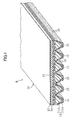
- FIG. 1 shows a V-ribbed belt B (a friction drive belt) according to the embodiment.
- the V-ribbed belt B of this embodiment is used in, for example, an accessory drive belt transmission system provided in an engine room of an automobile.
- the V-ribbed belt B of this embodiment has a belt total length of 700-3000 mm, a belt width of 10-36 mm and a belt thickness of 4.0-5.0 mm.
- the V-ribbed belt B of this embodiment includes a V-ribbed belt body 10 having a three-layer structure made of a compression rubber layer 11 provided on the inner periphery of the belt, an intermediate adhesion rubber layer 12, and a backing rubber layer 13 provided on the outer periphery of the belt.
- the adhesion rubber layer 12 of the V-ribbed belt body 10 includes a cord 14 embedded therein in a spiral having pitches adjacent to each other along the belt width.
- the compression rubber layer 11 has a plurality of V-ribs 15 rising inward relative to the inner periphery of the belt.
- the V-ribs 15 are each formed into a rib extending along the belt length and having a cross section in a substantially inverted triangular shape, and are arranged adjacent to each other along the belt width.
- Each of the V-ribs 15 has, for example, a rib height of 2.0-3.0 mm and a width of 1.0-3.6 mm at its root.
- the number of the V-ribs is, for example, from three to six (six in FIG. 1 ).
- the compression rubber layer 11 includes a surface rubber layer 11a formed into a layer shape extending along the entire pulley contact surface, and an inner rubber layer 11b provided toward the inside of the belt relative to the surface rubber layer 11 a.
- the surface rubber layer 11a has a thickness of 50-500 ⁇ m, for example.
- Each of the surface rubber layer 11a and the inner rubber layer 11b included in the compression rubber layer 11 is made of a rubber composition which is cross-linked with a cross-linker by application of heat and pressure to a non-crosslinked rubber composition produced by blending various compounding ingredients into a base material rubber.
- Examples of the base material rubber for the rubber composition forming each of the surface rubber layer 11a and the inner rubber layer 11b of the compression rubber layer 11 include: ethylene- ⁇ -olefin elastomers such as ethylene propylene copolymer (EPR), ethylenepropylene-diene terpolymer (EPDM), ethylene-octene copolymer, and ethylene-butene copolymer; chloroprene-rubber (CR); chlorosulfonated polyethylene rubber (CSM); and hydrogenated acrylonitrile rubber (H-NBR).
- EPR ethylene propylene copolymer
- EPDM ethylenepropylene-diene terpolymer
- CSM chlorosulfonated polyethylene rubber
- H-NBR hydrogenated acrylonitrile rubber
- an ethylene- ⁇ -olefin elastomer is preferably used as the base material rubber.
- the base material rubber may include either a single species or a mixture of two or more species.
- Examples of the compounding ingredients include reinforcing agents such as carbon blacks, softeners, processing aids, vulcanization aids, cross-linkers, vulcanization accelerators, resins for rubber compounding, and antioxidants.
- reinforcing agents such as carbon blacks, softeners, processing aids, vulcanization aids, cross-linkers, vulcanization accelerators, resins for rubber compounding, and antioxidants.
- carbon blacks used as the reinforcing agents include: channel black; furnace black such as SAF, ISAF, N-339, HAF, N-351, MAF, FEF, SRF, GPF, ECF, and N-234; thermal black such as FT and MT; and acetylene black.
- Silica may also be used as the reinforcing agent.
- the reinforcing agent may include either a single species or two or more species. In order that resistance to wear and resistance to bending fatigue will be well balanced, 30-80 parts by mass of the reinforcing agent is preferably blended into 100 parts by mass of the base material rubber.
- softeners examples include: petroleum softeners; mineral oil-based softeners such as paraffin wax; and vegetable oil based-softeners such as castor oil, cottonseed oil, linseed oil, rapeseed oil, soybean oil, palm oil, coconut oil, peanut oil, Japan wax, rosin, and pine oil.
- the softener may be made of either a single species or two or more species. For example, 2-30 parts by mass of the softener is blended into 100 parts by mass of the base material rubber.
- processing aids include stearic acids.
- the processing aid may include either a single species or two or more species. For example, 0.5-5 parts by mass of the processing aid is blended into 100 parts by mass of the base material rubber.
- vulcanization aids examples include metal oxides such as magnesium oxide and zinc oxide (zinc white).
- the vulcanization aid may include either a single species or two or more species. For example, 1-10 parts by mass of the vulcanization aid is blended into 100 parts by mass of the base material rubber.
- cross-linkers examples include sulfur and organic peroxides. Sulfur or an organic peroxide may be used alone as the cross-linker. Both of sulfur and the organic peroxide may also be used in combination. For example, 0.5-4.0 parts by mass of sulfur as the cross-linker is blended into 100 parts by mass of the base material rubber. For example, 0.5-8 parts by mass of the organic peroxide as the cross-linker is blended into 100 parts by mass of the base material rubber.
- vulcanization accelerators examples include metal oxides, metal carbonates, fatty acids and the derivatives thereof.
- the vulcanization accelerator may include either a single species or two or more species. For example, 0.5-8 parts by mass of the vulcanization accelerator is blended into 100 parts by mass of the base material rubber.
- Examples of the resins for rubber compounding include phenolic resin.
- the resin for rubber compounding may include either a single species or two or more species. For example, 0-20 parts by mass of the resin for rubber compounding is blended into 100 parts by mass of the base material rubber.
- antioxidants examples include amine-based agents, quinoline-based agents, hydroquinone derivatives, phenolic agents, phosphite-based agents.
- the antioxidant may include either a single species or two or more species. For example, 0-8 parts by mass of the antioxidant is blended into 100 parts by mass of the base material rubber.
- the average pore size of the pores 16 is preferably 40-150 ⁇ m and more preferably 80-120 ⁇ m.
- the average pore size of the pores 16 is calculated based on a number-average pore size of 50-100 pores measured by means of a surface image.
- the numerous pores 16 on the pulley contact surface of the surface rubber layer 11a may be made of partially cut away hollow particles 17 blended into the rubber composition forming the surface rubber layer 11a.
- the hollow particles 17 include EXPANCEL 092-120 (manufacturer: Japan Fillite Co., Ltd, particle size: 28-38 ⁇ m), EXPANCEL 009-80 (manufacturer: Japan Fillite Co., Ltd, particle size: 18-24 ⁇ m), ADVANCELL EMH204 (manufacturer: Sekisui Chemical Co., Ltd., particle size: 23-29 ⁇ m), ADVANCELL EMS-026 (manufacturer: Sekisui Chemical Co., Ltd., particle size: 25-35 ⁇ m), MATSUMOTO MICROSPHERE F-80S (manufacturer: Matsumoto Yushi-Seiyaku Co., Ltd., particle size: 20-30 ⁇ m), and MATSUMOTO MICROSPHERE F-80S (man
- the particle size of the hollow particles 17 is preferably 10-45 ⁇ m and more preferably 18-40 ⁇ m.
- the hollow particles 17 are blended preferably in an amount of 0.5-10 parts by mass and more preferably in an amount of 1-5 parts by mass into 100 parts by mass of the base material rubber.
- the numerous pores 16 on the pulley contact surface of the surface rubber layer 11a may be formed by partially cut away hollows produced by a foaming agent blended into the rubber composition forming the surface rubber layer 11a.
- a foaming agent examples include CELLMIC CAP-500 (manufacturer: Sankyo Kasei Co., Ltd.).
- the foaming agent is blended preferably in an amount of 1-15 parts by mass and more preferably in an amount of 3-8 parts by mass into 100 parts by mass of the base material rubber.
- the rubber composition forming the surface rubber layer 11a may contain short fibers.
- the short fibers are preferably oriented in the belt width direction. Part of the short fibers exposed at the pulley contact surface preferably has their ends protruding from the pulley contact surface.
- the short fibers include nylon short fibers, aramid short fibers, polyester short fibers, and cotton short fibers.
- the short fibers may be manufactured through an adhesion treatment in which the fibers are soaked in a resorcinol formaldehyde latex aqueous solution (an RFL aqueous solution) and then heated.
- the short fibers have a length of 0.2-3.0 mm, for example. For example, 3-30 parts by mass of the short fibers are blended into 100 parts by mass of the base material rubber.
- the rubber composition forming the surface rubber layer 11a may not contain short fibers.
- the surface rubber layer 11a has a storage modulus (E') at 25°C in the belt length direction ranging preferably 20-45 MPa, and more preferably 35-40 MPa.
- the storage modulus (E') at 25°C is measured in accordance with Japanese Industrial Standards (JIS) K6394.
- the rubber composition forming the inner rubber layer 11b does not contain the hollow particles 17 and the foaming agent. Accordingly, the inner rubber layer 11b does not contain hollows similar to the ones that the surface rubber layer 11 a contains.
- the rubber composition forming the inner rubber layer 11b preferably contains no short fibers.
- the storage modulus (E') at 25°C in the belt length direction of the inner rubber layer 11b is preferably higher than that of the surface rubber layer 11a, and is preferably 30-50 MPa and more preferably 35-45 MPa.
- the adhesion rubber layer 12 is formed into a band shape with a rectangular cross section and has a thickness of 1.0-2.5 mm, for example.
- the backing rubber layer 13 is also formed into a band shape with a rectangular cross section and has a thickness of 0.4-0.8 mm, for example.
- the surface of the backing rubber layer 13 preferably has a transferred weave pattern of woven fabric.
- Each of the adhesion rubber layer 12 and the backing rubber layer 13 is preferably made of a crosslinked rubber composition which is cross-linked with a cross-linker by application of heat and pressure to a non-crosslinked rubber composition produced by blending various compounding ingredients into base material rubber.
- the backing rubber layer 13 is preferably made of a rubber composition which is slightly harder than that of the adhesion rubber layer 12.
- Examples of the base material rubber for the rubber composition forming the adhesion rubber layer 12 and the backing rubber layer 13 include ethylene- ⁇ -olefin elastomers, chloroprene-rubber (CR), chlorosulfonated polyethylene rubber (CSM) and hydrogenated acrylonitrile rubber (H-NBR).
- the base material rubber of the adhesion rubber layer 12 and the backing rubber layer 13 is preferably the same as that of the compression rubber layer 11.
- examples of the compounding ingredients include reinforcing agents such as carbon blacks, softeners, processing aids, vulcanization aids, cross-linkers, vulcanization accelerators, resins for rubber compounding, and antioxidants.
- the rubber compositions forming the inner rubber layer 11b of the compression rubber layer 11, the adhesion rubber layer 12, and the backing rubber layer 13 may be either different from each other or the same in constitution.
- the cord 14 is made of twisted yarn of polyester fibers (PET), polyethylene naphthalate fibers (PEN), aramid fibers, vinylon fibers, etc.
- PET polyester fibers
- PEN polyethylene naphthalate fibers
- aramid fibers vinylon fibers, etc.
- the cord 14 is subjected to an adhesion treatment in which the cord is soaked in an RFL aqueous solution and then heated and/or an adhesion treatment in which the cord is soaked in rubber cement and then dried, prior to molding the V-ribbed belt.
- the compression rubber layer 11 includes the surface rubber layer 11 a and the inner rubber layer 11b, the numerous pores 16 are formed on the pulley contact surface of the surface rubber layer 11a, the storage modulus (E') at 25°C in the belt length direction of the inner rubber layer 11b is higher than that of the surface rubber layer 11a and is 30-50 MPa.
- This structure can reduce slip noise generated in running of the V-ribbed belt in a wet state and alleviate reduction of power transmission capacity in running of the V-ribbed belt in a wet state.
- a belt forming mold 20 is used to fabricate the V-ribbed belt B of the embodiment. As shown in FIGS. 3 and 4 , the belt forming mold 20 includes a cylindrical inner mold 21 and a cylindrical outer mold 22, which are provided concentrically.
- the inner mold 21 is made of a flexible material such as rubber.
- the outer mold 22 is made of a rigid material such as a metal.
- the inner periphery surface of the outer mold 22 serves as a molding surface, and grooves 23 for forming the V-ribs are provided in the axial direction at regular intervals on the inner periphery surface of the outer mold 22.
- the outer mold 22 is provided with a temperature control mechanism which allows a heating medium such as water vapor or a cooling medium such as water to flow.
- This belt forming mold 20 is provided with a pressurizing means for pressurizing and expanding the inner mold 21 from the inside.
- non-crosslinked rubber sheets 11a' and 11b' for the surface rubber layer and the inner rubber layer of the compression rubber layer 11 are first produced by blending the compounding agents into the base material rubber, kneading the resultant blend with a kneading machine such as a kneader and a Banbury mixer, and molding the resultant non-crosslinked rubber composition into a sheet shape by calender molding and the like.
- Non-crosslinked rubber sheets 12' and 13' for the adhesion rubber layer and the backing rubber layer are also produced in a similar manner. Twisted yarn 14' for forming the cord is subjected to the adhesion treatment in which the yarn is soaked in an RFL aqueous solution and then heated, and thereafter to the adhesion treatment in which the yarn is soaked in rubber cement and then dried.
- a rubber sleeve 25 is placed on the outer periphery of a cylindrical drum 24 having a smooth surface. Thereafter, the non-crosslinked rubber sheet 13' for the backing rubber layer and the non-crosslinked rubber sheet 12' for the adhesion rubber layer are wrapped around the rubber sleeve 25 in this order to form layers.
- the twisted yarn 14' for the cord is winded around the resultant layers in a helical manner with respect to the cylindrical inner mold 21.
- non-crosslinked rubber sheet 12' for the adhesion rubber layer the non-crosslinked rubber sheet 11b' for the inner rubber layer of the compression rubber layer 11, and the non-crosslinked rubber sheet 11a' for the surface rubber layer of the compression rubber layer 11 are wrapped around over the twisted yarn 14' in this order, thereby producing a multilayer member 10'.
- the rubber sleeve 25 on which the multilayer member 10' is formed is subsequently removed from the cylindrical drum 24, and then put inside the outer mold 22, as shown in FIG. 6 .
- the inner mold 21 is positioned inside the rubber sleeve 25 set in the outer mold 22, and then, hermetically sealed.
- the outer mold 22 is heated and the inner mold 21 is pressurized by introducing, for example, high-pressure air into its hermetically-sealed inner space.
- the inner mold 21 expands and the non-crosslinked rubber sheets 11a', 11b', 12' and 13' for molding belt of the multilayer member 10' are compressed on the molding surface of the outer mold 22.
- cross-linking is promoted in the sheets, and the sheets are integrated and combined with the twisted yarn 14'.
- the hollow particles 17 or the foaming agent contained in the non-crosslinked rubber sheet 11a' forms numerous hollows in the portion corresponding to the surface rubber 11a.
- the inner space of the inner mold 21 is reduced in pressure to be released from the hermetically sealed state, and the belt slab S formed between the inner mold 21 and the outer mold 22 with the rubber sleeve 25 interposed therebetween is removed.
- the belt slab S is cut into rings having a predetermined width, and each ring is turned inside out, thereby obtaining the V-ribbed belt B.
- the outer periphery of the belt slab S, i.e., the surface having the V-ribs 15 may be grinded, if necessary.
- This grinding partially cuts away the hollow particles 17 contained in the rubber composition forming the surface rubber layer 11a or the hollows formed by the foaming agent blended in the rubber composition forming the surface rubber layer 11a, thereby ensuring exposure of the pores 16 at the surface having the V-ribs 15.
- FIG. 9 shows a layout of pulleys of an accessory drive belt transmission system 30 for an automobile using the V-ribbed belt B of this embodiment.
- This accessory drive belt transmission system 30 is a serpentine drive type system in which the V-ribbed belt B is allowed to run around six pulleys including four ribbed pulleys and two flat pulleys to transmit power.
- the accessory drive belt transmission system 30 includes: a power steering pulley 31 which is an uppermost ribbed pulley; an AC generator pulley 32 which is a ribbed pulley disposed below the power steering pulley 31; a tensioner pulley 33 which is a flat pulley disposed downwardly leftward of the power steering pulley 31; a water-pump pulley 34 which is a flat pulley disposed below the tensioner pulley 33; a crankshaft pulley 35 which is a ribbed pulley disposed downwardly leftward of the tensioner pulley 33; and an air-conditioner pulley 36 which is a ribbed pulley disposed downwardly rightward of the crankshaft pulley 35.
- These pulleys are made of, for example, a pressed metal product, a casting product, or a resin molding product made of a nylon resin or phenolic resin, and their pulley diameters are 50-150 mm.
- the V-ribbed belt B is allowed to run sequentially around the following components: the power steering pulley 31 with the surface having the V-ribs 15 in contact with the power steering pulley 31; the tensioner pulley 33 with the belt back face in contact with the tensioner pulley 33; the crankshaft pulley 35 and then the air-conditioner pulley 36 with the surface having the V-ribs 15 in contact with the pulleys 35 and 36; the water-pump pulley 34 with the belt back face in contact with the water-pump pulley 34; the AC generator pulley 32 with the surface having the V-ribs 15 in contact with the AC generator pulley 32; and then the power steering pulley 31 again.
- Belt span lengths which are the lengths of the parts of the V-ribbed belt B between the pulleys are 50-300 mm, for example. Misalignment produced between the pulleys is 0-2°.
- V-ribbed belt B is applied as the friction drive belt in this embodiment, the present disclosure is not particularly limited to this embodiment.
- a raw-edge type V-belt may be applicable to the present disclosure.
- the V-ribbed belt body 10 of this embodiment is constituted by the compression rubber layer 11, the adhesion rubber layer 12, and the backing rubber layer 13, the present disclosure is not particularly limited to this embodiment.
- the V-ribbed belt body 10 may be constituted by the compression rubber layer 11, the adhesion rubber layer 12, and reinforcement fabric, which is provided in place of the backing rubber layer 13.
- This reinforcement fabric is made of, for example, woven fabric, knitted fabric, or unwoven fabric made of fibers such as cotton fibers, polyamide fibers, polyester fibers, and aramid fibers.
- the accessory drive belt transmission system 30 is described as the belt transmission system in this embodiment, the present disclosure is not particularly limited to this embodiment.
- the present disclosure is applicable to belt transmission systems for general industries, for example.
- each of surface rubbers 1-10 was prepared as the rubber composition for the surface rubber layer of the compression rubber layer.
- the constitution of each of surface rubbers 1-10 is also shown in Table 1 or 2.
- EPDM manufactured by mass of EPDM (manufacturer: JSR Corporation, trade name: EP22) used as the base material rubber was blended with 80 parts by mass of an HAF carbon black (manufacturer: Tokai Carbon Co., Ltd., trade name: SEAST 3), 8 parts by mass of paraffinic oil (manufacturer: Sun Oil Company, trade name: SUNPAR 2280), 1 part by mass of a processing aid (manufacturer: NOF Corporation, trade name: STEARIC ACID CAMELLIA), 5 parts by mass of a vulcanization aid (manufacturer: Sakai Chemical Industry Co., Ltd., trade name: Zinc White No.1), 2.3 parts by mass of a vulcanizer (manufacturer: Hosoi Chemical Industry Co., Ltd., trade name OIL SULFUR), 4 parts by mass of a vulcanization accelerator (manufacturer: Ouchi Shinko Chemical Industrial Co., Ltd., trade name: EP-150), 3 parts by
- a non-crosslinked rubber sheet as surface rubber 2 was produced by the same method as that of surface rubber 1 except for changing the amount (with respect to 100 parts by mass of the base material rubber) of the paraffinic oil to 4 parts by mass, the vulcanization accelerator to 6 parts by mass, and the resin for rubber compounding to 10 parts by mass.
- a non-crosslinked rubber sheet as surface rubber 3 was produced by the same method as that of surface rubber 1 except for changing the amount (with respect to 100 parts by mass of the base material rubber) of the HAF carbon black to 70 parts by mass, the paraffinic oil to 5 parts by mass, and the resin for rubber compounding to 5 parts by mass, and blending 5 parts by mass of a foaming agent (manufacturer: Sankyo Kasei Co., Ltd., trade name: CELLMIC CAP-500) as a substitute for the hollow particles into 100 parts by mass of the base material rubber.
- a non-crosslinked rubber sheet as surface rubber 4 was produced by the same method as that of surface rubber 1 except for changing the amount (with respect to 100 parts by mass of the base material rubber) of the HAF carbon black to 70 parts by mass.
- a non-crosslinked rubber sheet as surface rubber 5 was produced by the same method as that of surface rubber 1 except for changing the amount (with respect to 100 parts by mass of the base material rubber) of the HAF carbon black to 90 parts by mass, the paraffinic oil to 5 parts by mass, and the resin for rubber compounding to 5 parts by mass.
- a non-crosslinked rubber sheet as surface rubber 6 was produced by the same method as that of surface rubber 2 except that no hollow particles were blended into the base material rubber.
- a non-crosslinked rubber sheet as surface rubber 7 was produced by the same method as that of surface rubber 2 except for changing the amount (with respect to 100 parts by mass of the base material rubber) of the hollow particles to 0.5 parts by mass.
- a non-crosslinked rubber sheet as surface rubber 8 was produced by the same method as that of surface rubber 2 except for changing the amount (with respect to 100 parts by mass of the base material rubber) of the hollow particles to 10 parts by mass.
- a non-crosslinked rubber sheet as surface rubber 9 was produced by the same method as that of surface rubber 2 except for changing the amount (with respect to 100 parts by mass of the base material rubber) of the hollow particles to 12 parts by mass and the resin for rubber compounding to 13 parts by mass.
- a non-crosslinked rubber sheet as surface rubber 10 was produced by the same method as that of surface rubber 1 except that 25 parts by mass of nylon short fibers (manufacturer: Asahi Kasei Corporation, trade name: LEONA 66, fiber length: 1 mm) were blended into 100 parts by mass of the base material rubber, in addition to the ingredients contained in surface rubber 1.
- nylon short fibers manufactured by Asahi Kasei Corporation, trade name: LEONA 66, fiber length: 1 mm
- each of inner rubbers 1-6 was prepared as the rubber composition for the inner rubber layer of the compression rubber layer.
- the constitution of each of inner rubbers 1-6 is also shown in Table 3.
- EPDM manufactured by mass of EPDM (manufacturer: JSR Corporation, trade name: EP22) used as the base material rubber was blended with 70 parts by mass of an HAF carbon black (manufacturer: Tokai Carbon Co., Ltd., trade name: SEAST 3), 5 parts by mass of paraffinic oil (manufacturer: Sun Oil Company, trade name: SUNPAR 2280), 1 part by mass of a processing aid (manufacturer: NOF Corporation, trade name: STEARIC ACID CAMELLIA), 5 parts by mass of a vulcanization aid (manufacturer: Sakai Chemical Industry Co., Ltd., trade name: Zinc White No.1), 2.3 parts by mass of a vulcanizer (manufacturer: Hosoi Chemical Industry Co., Ltd., trade name OIL SULFUR), 4 parts by mass of a vulcanization accelerator (manufacturer: Ouchi Shinko Chemical Industrial Co., Ltd., trade name: EP-150), and 1.7
- a non-crosslinked rubber sheet as inner rubber 2 was produced by the same method as that of inner rubber 1 except for changing the amount (with respect to 100 parts by mass of the base material rubber) of the HAF carbon black to 80 parts by mass, the paraffinic oil to 4 parts by mass, the vulcanization accelerator to 6 parts by mass, and the resin for rubber compounding to 10 parts by mass.
- a non-crosslinked rubber sheet as inner rubber 3 was produced by the same method as that of inner rubber 1 except for changing the amount (with respect to 100 parts by mass of the base material rubber) of the resin for rubber compounding to 5 parts by mass.
- a non-crosslinked rubber sheet as inner rubber 4 was produced by the same method as that of inner rubber 1 except for changing the amount (with respect to 100 parts by mass of the base material rubber) of the resin for rubber compounding to 5 parts by mass, and further adding 5 parts by mass of hollow particles (manufacturer: Sekisui Chemical Co., Ltd., trade name: ADVANCELL EMS-026) with respect to 100 parts by mass of the base material rubber.
- a non-crosslinked rubber sheet as inner rubber 5 was produced by the same method as that of inner rubber 1 except for changing the amount (with respect to 100 parts by mass of the base material rubber) of the HAF carbon black to 60 parts by mass and the paraffmic oil to 10 parts by mass.
- a non-crosslinked rubber sheet as inner rubber 6 was produced by the same method as that of inner rubber 1 except for changing the amount (with respect to 100 parts by mass of the base material rubber) of the HAF carbon black to 90 parts by mass, the paraffinic oil to 4 parts by mass, the vulcanizer to 2.5 parts by mass, the vulcanization accelerator to 6 parts by mass of, and the resin for rubber compounding to 10 parts by mass.
- a non-crosslinked rubber sheet made of an EPDM rubber composition was produced as a rubber composition for the adhesion rubber layer, and a non-crosslinked rubber sheet made of an EPDM rubber composition was produced as a rubber composition for the backing rubber layer.
- Twisted yarn made of polyester fibers with the structure of 1,100 dtex/2 x 3 (the number of second twists: 9.5 T/10 cm (Z), the number of first twists: 2.19 T/10 cm, manufacturer: Teijin Limited) was used for the cord.
- the twisted yarn was sequentially subjected to: a treatment in which the twisted yarn was soaked in a toluene solution containing 20 % by mass (solid content concentration) of isocyanate and then heat-dried at 240°C for 40 seconds; a treatment in which the twisted yarn was soaked in an RFL aqueous solution and then heat-dried at 200°C for 80 seconds; and a treatment in which the twisted yarn was soaked in rubber cement prepared by dissolving the rubber composition for the adhesion rubber layer in toluene and then heat-dried at 60°C for 40 seconds.
- the configurations of the V-ribbed belts are shown in Tables 4-9.
- the V-ribbed belt of Example 1 was fabricated by a method similar to the fabrication method of the embodiment, using surface rubber 1 as the rubber composition for the surface rubber layer of the compression rubber layer, inner rubber 1 as the rubber composition for the inner rubber layer of the compression rubber layer, the rubber composition for the adhesion rubber layer, the rubber composition for the backing rubber layer, and the twisted yarn for the cord.
- the V-ribbed belt of Example 1 had a belt total length of 1117 mm, a belt thickness of 4.3 mm, a V-rib height of 2.0 mm, and three V-ribs (belt width: 10.68 mm).
- the surface rubber layer of the V-ribbed belt of Example 1 had a thickness of 400 ⁇ m.
- the V-ribbed belt of Example 2 was fabricated by the same method as that of Example 1 except that surface rubber 2 was used as the rubber composition for the surface rubber layer of the compression rubber layer and inner rubber 2 was used as the rubber composition for the inner rubber layer of the compression rubber layer.
- the V-ribbed belt of Example 3 was fabricated by the same method as that of Example 1 except that surface rubber 3 was used as the rubber composition for the surface rubber layer of the compression rubber layer and inner rubber 3 was used as the rubber composition for the inner rubber layer of the compression rubber layer.
- the V-ribbed belt of Example 4 was fabricated by the same method as that of Example 1 except that the surface rubber layer had a thickness of 40 ⁇ m.
- the V-ribbed belt of Example 5 was fabricated by the same method as that of Example 1 except that the surface rubber layer had a thickness of 60 ⁇ m.
- the V-ribbed belt of Example 6 was fabricated by the same method as that of Example 1 except that the surface rubber layer had a thickness of 450 ⁇ m.
- the V-ribbed belt of Example 7 was fabricated by the same method as that of Example 1 except that the surface rubber layer had a thickness of 550 ⁇ m.
- the V-ribbed belt of Example 8 was fabricated by the same method as that of Example 1 except that surface rubber 1 was used as the rubber composition for the surface rubber layer of the compression rubber layer, inner rubber 3 was used as the rubber composition for the inner rubber layer of the compression rubber layer, and the storage modulus E' in the belt length direction of the surface rubber layer, which will be described later, and the average pore size of the pores were set at 35.7 MPa and 44 ⁇ m, respectively, by regulating the molding pressure.
- the V-ribbed belt of Example 9 was fabricated by the same method as that of Example 8 except that the storage modulus E' in the belt length direction of the surface rubber layer and the average pore size of the pores were set at 25.4 MPa and 147 ⁇ m, respectively, by regulating the molding pressure.
- the V-ribbed belt of Example 10 was fabricated by the same method as that of Example 8 except that the storage modulus E' in the belt length direction of the surface rubber layer and the average pore size of the pores were set at 23.4 MPa and 169 ⁇ m, respectively, by regulating the molding pressure.
- the V-ribbed belt of Example 11 was fabricated by the same method as that of Example 2 except that surface rubber 7 was used as the rubber composition for the surface rubber layer of the compression rubber layer.
- the V-ribbed belt of Example 12 was fabricated by the same method as that of Example 2 except that surface rubber 8 was used as the rubber composition for the surface rubber layer of the compression rubber layer.
- the V-ribbed belt of Example 13 was fabricated by the same method as that of Example 2 except that surface rubber 9 was used as the rubber composition for the surface rubber layer of the compression rubber layer.
- the V-ribbed belt of Comparative Example 1 was fabricated by the same method as that of Example 1 except that inner rubber 3 was used as the rubber composition for the surface rubber layer of the compression rubber layer and as the rubber composition for the inner rubber layer of the compression rubber layer.
- the compression rubber layer of Comparative Example 1 had a single layer structure made of inner rubber 3.
- the V-ribbed belt of Comparative Example 2 was fabricated by the same method as that of Example 1 except that inner rubber 4 was used as the rubber composition for the surface rubber layer of the compression rubber layer and as the rubber composition for the inner rubber layer of the compression rubber layer.
- the compression rubber layer of Comparative Example 2 had a single layer structure made of inner rubber 4.
- the V-ribbed belt of Comparative Example 3 was fabricated by the same method as that of Example 1 except that surface rubber 4 was used as the rubber composition for the surface rubber layer of the compression rubber layer and inner rubber 5 was used as the rubber composition for the inner rubber layer of the compression rubber layer.
- the V-ribbed belt of Comparative Example 4 was fabricated by the same method as that of Example 1 except that surface rubber 2 was used as the rubber composition for the surface rubber layer of the compression rubber layer and inner rubber 6 was used as the rubber composition for the inner rubber layer of the compression rubber layer.
- the V-ribbed belt of Comparative Example 5 was fabricated by the same method as that of Example 1 except that surface rubber 5 was used as the rubber composition for the surface rubber layer of the compression rubber layer and inner rubber 1 was used as the rubber composition for the inner rubber layer of the compression rubber layer.
- the V-ribbed belt of Comparative Example 6 was fabricated by the same method as that of Example 8 except that the storage modulus E' in the belt length direction of the surface rubber layer and the average pore size of the pores were set at 41.2 MPa and 35 ⁇ m, respectively, by regulating the molding pressure.
- the V-ribbed belt of Comparative Example 7 was fabricated by the same method as that of Example 2 except that surface rubber 6 was used as the rubber composition for the surface rubber layer of the compression rubber layer.
- the V-ribbed belt of Comparative Example 8 was fabricated by the same method as that of Example 1 except that surface rubber 10 was used as the rubber composition for the surface rubber layer of the compression rubber layer.
- Example 1 Example 2
- Example 3 Surface rubber layer Surface rubber 1 Surface rubber 2 Surface rubber 3 Thickness of surface rubber layer ( ⁇ m) 400 400 400 E'(MPa) of surface rubber layer 28.6 43.6 33.6
- Inner rubber layer Inner rubber 1 Inner rubber 2
- Example 4 Example 5
- Example 6 Example 7 Surface rubber layer Surface rubber 1 Surface rubber 1 Surface rubber 1 Surface rubber 1 Surface rubber 1 Thickness of surface rubber layer ( ⁇ m) 40 60 400 450 550 E'(MPa) of surface rubber layer 28.6 28.6 28.6 28.6 28.6 Inner rubber layer Inner rubber 1 Inner rubber 1 Inner rubber 1 Inner rubber 1 E'(MPa) of inner rubber layer 32.6 32.6 32.6 32.6 32.6 32.6 Means for forming pores Hollow particles Hollow particles Hollow particles Hollow particles Hollow particles Hollow particles Hollow particles Hollow particles Average pore size ( ⁇ m) 86 86 86 86 86 86 86 Bending fatigue lifetime (hours) 1000 or more 1000 or more 1000 or more 1000 or more 856 Slip noise evaluation Medium Low None None None None None None None None None None None None None None None None None None None None None None None None None None None None None None None None None None None None None None None None None None None None None None None None None None None None None None None None None None None None None None None None None None None None None None None None None None None
- Example 10 Surface rubber layer Surface rubber 1 Surface rubber 1 Surface rubber 1 Surface rubber 1 Thickness of surface rubber layer ( ⁇ m) 400 400 400 400 E'(MPa) of surface rubber layer 41.2 35.7 25.4 23.4 Inner rubber layer Inner rubber 3 Inner rubber 3 Inner rubber 3 E'(MPa) of inner rubber layer 36.1 36.1 36.1 36.1 Means for forming pores Hollow particles Hollow particles Hollow particles Hollow particles Average pore size ( ⁇ m) 35 44 147 169 Bending fatigue lifetime (hours) 1000 or more 1000 or more 921 836 Slip noise evaluation Loud Medium None None None None None None None None None None,
- Example 1 Comparative Example 8 Surface rubber layer Surface rubber 1 Surface rubber 10 Thickness of surface rubber layer ( ⁇ m) 400 400 E'(MPa) of surface rubber layer 28.6 35.2 Inner rubber layer Inner rubber 1 Inner rubber 1 E'(MPa) of inner rubber layer 32.6 32.6 Means for forming pores Hollow particles Hollow particles Average pore size ( ⁇ m) 86 89 Bending fatigue lifetime (hours) 1000 or more 537 Slip noise evaluation None None
- each of surface rubbers 1-10 and inner rubbers 1-6 was molded into a rubber sheet, and a predetermined test peace which was cut out from each rubber sheet was subjected to a measurement of the storage modulus E' at 25°C in the drawing direction corresponding to the belt length direction.
- the molding pressures applied to the rubber sheets were made to correspond to those of the belt molding condition of Examples 1-7 and 11-13 and Comparative Examples 1-5 and 7-8, exclusive of Examples 8-10 and Comparative Example 6.
- FIG. 10 shows a layout of pulleys in a multi-axis bending belt running test machine 40 used to evaluate the resistance to bending fatigue of the V-ribbed belt B.
- the multi-axis bending belt running test machine 40 has a structure including: a first driven pulley 41 and a drive pulley 42 which are ribbed pulleys with a pulley diameter of 45 mm and disposed at upper and lower positions, respectively; a pair of idler pulleys 43 which are flat pulleys with a pulley diameter of 50 mm and disposed to the right of the vertical midway between the pulleys 41 and 42; and a second driven pulley 44 which is a ribbed pulley with a pulley diameter of 45 mm and disposed to the right of the vertical midway between the pulleys 43.
- Each V-ribbed belt of Examples 1-13 and Comparative Examples 1-8 was set in the multi-axis bending belt running test machine 40 in the following manner.
- Each V-ribbed belt was wrapped around the first and second driven pulleys 41 and 44 and the drive pulley 42 with the V-ribs in contact with the pulleys 41, 44 and 42, and around the pair of the idler pulleys 43 with the belt back face in contact with the pulleys 43.
- a deadweight of 588.4 N was imposed on the first driven pulley 41 by setting the first driven pulley 41 in an upwardly pulled state.
- Each V-ribbed belt B was allowed to run by rotating the drive pulley 42 at 5100 rpm. Then, the period of time before a crack was observed in any of the V-ribs on each V-ribbed belt B was measured as a bending fatigue lifetime.
- FIG. 11 shows a layout of pulleys in a belt running test machine 50 for measurement of slip noise produced by the V-ribbed belt B.
- the belt running test machine 50 has a structure including: a first driven pulley 51 and a drive pulley 52 which are ribbed pulleys with a pulley diameter of 120 mm and disposed at upper and lower positions, respectively; an idler pulley 53 which has a pulley diameter of 70 mm and is disposed vertically midway between the pulleys 51 and 52; and a second driven pulley 54 which is a ribbed pulley with a pulley diameter of 55 mm and disposed to the right of the idler pulley 53.
- the idler pulley 53 and the second driven pulley 54 are arranged in such a manner that the wrap-around angle of the V-ribbed belt on each of the pulleys 53 and 54 is 90°.
- Each V-ribbed belt of Examples 1-13 and Comparative Examples 1-8 was set in the belt running test machine 50 for measurement of slip noise in the following manner.
- Each V-ribbed belt was wrapped around the first and second driven pulleys 51 and 54 and the drive pulley 52 with the V-ribs in contact with the pulleys 51, 54 and 52 and around the idler pulley 53 with the belt back face in contact with the pulley 53, torque loads of 2.5 kW per V-rib were applied to the first driven pulley 51, and the second driven pulley 54 was set in a sideways-pulled state such that a set weight of 277 N was imposed per V-rib.
- the V-ribbed belt B was allowed to run by rotating the drive pulley 52 at 4900 rpm, and water was poured on the drive pulley 52 at a rate of 200 ml/min. Then, the slip noise produced in running of the V-ribbed belt B was evaluated by means of a sensory evaluation and graded from "loud” to "none.”
- the storage modulus E' at 25°C in the belt length direction was as follows: surface rubber 1, 28.6 MPa; surface rubber 2, 43.6 MPa; surface rubber 3, 33.6 MPa; surface rubber 4, 26.4 MPa; surface rubber 5, 36.5 MPa; surface rubber 6, 47.7 MPa; surface rubber 7, 44.3 MPa; surface rubber 8, 35.7 MPa; surface rubber 9, 27.4 MPa; surface rubber 10, 35.2 MPa; inner rubber 1, 32.6 MPa; inner rubber 2, 47.7 MPa; inner rubber 3, 36.1 MPa; inner rubber 4, 35.5 MPa; inner rubber 5, 27.8 MPa; and inner rubber 6, 51.3 MPa.
- the average pore size of the pores was as follows: surface rubber 1, 86 ⁇ m; surface rubber 2, 82 ⁇ m, surface rubber 3, 85 ⁇ m; surface rubber 4, 89 ⁇ m; surface rubber 5, 95 ⁇ m; surface rubber 7, 92 ⁇ m; surface rubber 8, 84 ⁇ m; surface rubber 9, 92 ⁇ m; surface rubber 10, 89 ⁇ m; and inner rubber 2, 94 ⁇ m.
- the bending fatigue lifetime was as follows: Example 1, 1000 hours or more; Example 2, 960 hours; Example 3, 1000 hours or more; Example 4, 1000 hours or more; Example 5, 1000 hours or more; Example 6, 1000 hours or more; Example 7, 856 hours; Example 8, 1000 hours or more; Example 9, 921 hours; Example 10, 836 hours; Example 11, 1000 hours or more, Example 12, 824 hours; Example 13, 755 hours; Comparative Example 1, 1000 hours or more; Comparative Example 2, 648 hours; Comparative Example 3, 1000 hours or more; Comparative Example 4, 600 hours; Comparative Example 5, 720 hours; Comparative Example 6, 1000 hours or more; Comparative Example 7, 1000 hours or more; and Comparative Example 8, 537 hours.
- the present disclosure is useful for friction drive belts.
Landscapes
- Engineering & Computer Science (AREA)
- General Engineering & Computer Science (AREA)
- Mechanical Engineering (AREA)
- Compositions Of Macromolecular Compounds (AREA)
Abstract
Description
- The present disclosure relates to friction drive belts.
- V-ribbed belts having a large number of pores on their pulley contact surfaces are known.
- For example,
Patent Document 1 describes a V-ribbed belt in which a portion including a pulley contact surface is at least partially made of a porous rubber composition having an air content of 5-20%. - Patent Document 2 describes a V-ribbed belt having a two-layer structure including an outer adhesion rubber layer and an inner compression rubber layer. In this V-ribbed belt, hollow particles are blended into a rubber composition forming the compression rubber layer, and part of the hollow particles exposed at the pulley contact surface is partially cut away to form a large number of cellular pores.
-
- PATENT DOCUMENT 1: Japanese Patent Publication No
2007-255635 - PATENT DOCUMENT 2: International Patent Publication No.
WO2008/007647 - The present disclosure relates to a friction drive belt including a compression rubber layer which is provided on an inner periphery of a belt body and transmits power between pulleys upon coming into contact with the pulleys, wherein the compression rubber layer includes a surface rubber layer including numerous pores on a pulley contact surface, and an inner rubber layer which is provided toward an inside of the belt relative to the surface rubber layer and whose storage modulus at 25°C in a belt length direction is higher than that of the surface rubber layer and is in the range from 30 to 50 MPa.
-
- [
FIG. 1] FIG. 1 is a perspective view illustrating a V-ribbed belt according to an embodiment. - [
FIG. 2] FIG. 2(a) is an enlarged cross-sectional view of a principal portion of the V-ribbed belt of the embodiment in which hollow particles are used.FIG. 2(b) is an enlarged cross-sectional view of a principal portion of a V-ribbed belt of the embodiment in which a foaming agent is used. - [
FIG. 3] FIG. 3 is a longitudinal cross-sectional view of a belt forming mold. - [
FIG. 4] FIG. 4 is an enlarged longitudinal cross-sectional view of a portion of the belt forming mold. - [
FIG. 5] FIG. 5 is an illustration showing a step of forming a multilayer member. - [
FIG. 6] FIG. 6 is an illustration showing a step of setting the multilayer member in an outer mold. - [
FIG. 7] FIG. 7 is an illustration showing a step of setting the outer mold outside an inner mold. - [
FIG. 8] FIG. 8 is an illustration showing a step of forming a belt slab. - [
FIG. 9] FIG. 9 is a diagram showing a layout of pulleys in an accessory drive belt transmission system for an automobile according to the embodiment. - [
FIG. 10] FIG. 10 is a diagram showing a layout of pulleys in a multi-axis bending belt running test machine used to evaluate resistance to bending fatigue. - [
FIG. 11] FIG. 11 is a diagram showing a layout of pulleys in a belt running test machine for a measurement of slip noise. - An embodiment will be described below in detail with reference to the drawings.
-
FIG. 1 shows a V-ribbed belt B (a friction drive belt) according to the embodiment. The V-ribbed belt B of this embodiment is used in, for example, an accessory drive belt transmission system provided in an engine room of an automobile. The V-ribbed belt B of this embodiment has a belt total length of 700-3000 mm, a belt width of 10-36 mm and a belt thickness of 4.0-5.0 mm. - The V-ribbed belt B of this embodiment includes a V-ribbed
belt body 10 having a three-layer structure made of acompression rubber layer 11 provided on the inner periphery of the belt, an intermediateadhesion rubber layer 12, and abacking rubber layer 13 provided on the outer periphery of the belt. Theadhesion rubber layer 12 of the V-ribbedbelt body 10 includes acord 14 embedded therein in a spiral having pitches adjacent to each other along the belt width. - The
compression rubber layer 11 has a plurality of V-ribs 15 rising inward relative to the inner periphery of the belt. The V-ribs 15 are each formed into a rib extending along the belt length and having a cross section in a substantially inverted triangular shape, and are arranged adjacent to each other along the belt width. Each of the V-ribs 15 has, for example, a rib height of 2.0-3.0 mm and a width of 1.0-3.6 mm at its root. The number of the V-ribs is, for example, from three to six (six inFIG. 1 ). - The
compression rubber layer 11 includes asurface rubber layer 11a formed into a layer shape extending along the entire pulley contact surface, and aninner rubber layer 11b provided toward the inside of the belt relative to thesurface rubber layer 11 a. Thesurface rubber layer 11a has a thickness of 50-500 µm, for example. - Each of the
surface rubber layer 11a and theinner rubber layer 11b included in thecompression rubber layer 11 is made of a rubber composition which is cross-linked with a cross-linker by application of heat and pressure to a non-crosslinked rubber composition produced by blending various compounding ingredients into a base material rubber. - Examples of the base material rubber for the rubber composition forming each of the
surface rubber layer 11a and theinner rubber layer 11b of thecompression rubber layer 11 include: ethylene-α-olefin elastomers such as ethylene propylene copolymer (EPR), ethylenepropylene-diene terpolymer (EPDM), ethylene-octene copolymer, and ethylene-butene copolymer; chloroprene-rubber (CR); chlorosulfonated polyethylene rubber (CSM); and hydrogenated acrylonitrile rubber (H-NBR). Among the examples, an ethylene-α-olefin elastomer is preferably used as the base material rubber. The base material rubber may include either a single species or a mixture of two or more species. The rubber composition forming thesurface rubber layer 11a and that forming theinner rubber layer 11b may be either the same or different from each other. - Examples of the compounding ingredients include reinforcing agents such as carbon blacks, softeners, processing aids, vulcanization aids, cross-linkers, vulcanization accelerators, resins for rubber compounding, and antioxidants.
- Examples of the carbon blacks used as the reinforcing agents include: channel black; furnace black such as SAF, ISAF, N-339, HAF, N-351, MAF, FEF, SRF, GPF, ECF, and N-234; thermal black such as FT and MT; and acetylene black. Silica may also be used as the reinforcing agent. The reinforcing agent may include either a single species or two or more species. In order that resistance to wear and resistance to bending fatigue will be well balanced, 30-80 parts by mass of the reinforcing agent is preferably blended into 100 parts by mass of the base material rubber.
- Examples of the softeners include: petroleum softeners; mineral oil-based softeners such as paraffin wax; and vegetable oil based-softeners such as castor oil, cottonseed oil, linseed oil, rapeseed oil, soybean oil, palm oil, coconut oil, peanut oil, Japan wax, rosin, and pine oil. The softener may be made of either a single species or two or more species. For example, 2-30 parts by mass of the softener is blended into 100 parts by mass of the base material rubber.
- Examples of the processing aids include stearic acids. The processing aid may include either a single species or two or more species. For example, 0.5-5 parts by mass of the processing aid is blended into 100 parts by mass of the base material rubber.
- Examples of the vulcanization aids include metal oxides such as magnesium oxide and zinc oxide (zinc white). The vulcanization aid may include either a single species or two or more species. For example, 1-10 parts by mass of the vulcanization aid is blended into 100 parts by mass of the base material rubber.
- Examples of the cross-linkers include sulfur and organic peroxides. Sulfur or an organic peroxide may be used alone as the cross-linker. Both of sulfur and the organic peroxide may also be used in combination. For example, 0.5-4.0 parts by mass of sulfur as the cross-linker is blended into 100 parts by mass of the base material rubber. For example, 0.5-8 parts by mass of the organic peroxide as the cross-linker is blended into 100 parts by mass of the base material rubber.
- Examples of the vulcanization accelerators include metal oxides, metal carbonates, fatty acids and the derivatives thereof. The vulcanization accelerator may include either a single species or two or more species. For example, 0.5-8 parts by mass of the vulcanization accelerator is blended into 100 parts by mass of the base material rubber.
- Examples of the resins for rubber compounding include phenolic resin. The resin for rubber compounding may include either a single species or two or more species. For example, 0-20 parts by mass of the resin for rubber compounding is blended into 100 parts by mass of the base material rubber.
- Examples of the antioxidants include amine-based agents, quinoline-based agents, hydroquinone derivatives, phenolic agents, phosphite-based agents. The antioxidant may include either a single species or two or more species. For example, 0-8 parts by mass of the antioxidant is blended into 100 parts by mass of the base material rubber.
-
Numerous pores 16 are formed on the pulley contact surface of thesurface rubber layer 11a, i.e. on the surfaces of the V-ribs 15. The average pore size of thepores 16 is preferably 40-150 µm and more preferably 80-120 µm. The average pore size of thepores 16 is calculated based on a number-average pore size of 50-100 pores measured by means of a surface image. - As shown in
FIG. 2(a) , thenumerous pores 16 on the pulley contact surface of thesurface rubber layer 11a may be made of partially cut awayhollow particles 17 blended into the rubber composition forming thesurface rubber layer 11a. Examples of thehollow particles 17 include EXPANCEL 092-120 (manufacturer: Japan Fillite Co., Ltd, particle size: 28-38 µm), EXPANCEL 009-80 (manufacturer: Japan Fillite Co., Ltd, particle size: 18-24 µm), ADVANCELL EMH204 (manufacturer: Sekisui Chemical Co., Ltd., particle size: 23-29 µm), ADVANCELL EMS-026 (manufacturer: Sekisui Chemical Co., Ltd., particle size: 25-35 µm), MATSUMOTO MICROSPHERE F-80S (manufacturer: Matsumoto Yushi-Seiyaku Co., Ltd., particle size: 20-30 µm), and MATSUMOTO MICROSPHERE F-190D (manufacturer: Matsumoto Yushi-Seiyaku Co., Ltd., particle size: 30-40 µm). The particle size of thehollow particles 17 is preferably 10-45 µm and more preferably 18-40 µm. Thehollow particles 17 are blended preferably in an amount of 0.5-10 parts by mass and more preferably in an amount of 1-5 parts by mass into 100 parts by mass of the base material rubber. - As shown in
FIG. 2(b) , thenumerous pores 16 on the pulley contact surface of thesurface rubber layer 11a may be formed by partially cut away hollows produced by a foaming agent blended into the rubber composition forming thesurface rubber layer 11a. Examples of the foaming agent include CELLMIC CAP-500 (manufacturer: Sankyo Kasei Co., Ltd.). The foaming agent is blended preferably in an amount of 1-15 parts by mass and more preferably in an amount of 3-8 parts by mass into 100 parts by mass of the base material rubber. - The rubber composition forming the
surface rubber layer 11a may contain short fibers. The short fibers are preferably oriented in the belt width direction. Part of the short fibers exposed at the pulley contact surface preferably has their ends protruding from the pulley contact surface. Examples of the short fibers include nylon short fibers, aramid short fibers, polyester short fibers, and cotton short fibers. For example, the short fibers may be manufactured through an adhesion treatment in which the fibers are soaked in a resorcinol formaldehyde latex aqueous solution (an RFL aqueous solution) and then heated. The short fibers have a length of 0.2-3.0 mm, for example. For example, 3-30 parts by mass of the short fibers are blended into 100 parts by mass of the base material rubber. The rubber composition forming thesurface rubber layer 11a may not contain short fibers. - The
surface rubber layer 11a has a storage modulus (E') at 25°C in the belt length direction ranging preferably 20-45 MPa, and more preferably 35-40 MPa. The storage modulus (E') at 25°C is measured in accordance with Japanese Industrial Standards (JIS) K6394. - The rubber composition forming the
inner rubber layer 11b does not contain thehollow particles 17 and the foaming agent. Accordingly, theinner rubber layer 11b does not contain hollows similar to the ones that thesurface rubber layer 11 a contains. The rubber composition forming theinner rubber layer 11b preferably contains no short fibers. The storage modulus (E') at 25°C in the belt length direction of theinner rubber layer 11b is preferably higher than that of thesurface rubber layer 11a, and is preferably 30-50 MPa and more preferably 35-45 MPa. - The
adhesion rubber layer 12 is formed into a band shape with a rectangular cross section and has a thickness of 1.0-2.5 mm, for example. Thebacking rubber layer 13 is also formed into a band shape with a rectangular cross section and has a thickness of 0.4-0.8 mm, for example. In order to reduce noise produced between the belt back face and a flat pulley in contact with the belt back face, the surface of thebacking rubber layer 13 preferably has a transferred weave pattern of woven fabric. - Each of the
adhesion rubber layer 12 and thebacking rubber layer 13 is preferably made of a crosslinked rubber composition which is cross-linked with a cross-linker by application of heat and pressure to a non-crosslinked rubber composition produced by blending various compounding ingredients into base material rubber. In order to reduce adhesion produced by contact between the belt back face and the flat pulley, thebacking rubber layer 13 is preferably made of a rubber composition which is slightly harder than that of theadhesion rubber layer 12. - Examples of the base material rubber for the rubber composition forming the
adhesion rubber layer 12 and thebacking rubber layer 13 include ethylene-α-olefin elastomers, chloroprene-rubber (CR), chlorosulfonated polyethylene rubber (CSM) and hydrogenated acrylonitrile rubber (H-NBR). The base material rubber of theadhesion rubber layer 12 and thebacking rubber layer 13 is preferably the same as that of thecompression rubber layer 11. - In a manner similar to the
compression rubber layer 11, examples of the compounding ingredients include reinforcing agents such as carbon blacks, softeners, processing aids, vulcanization aids, cross-linkers, vulcanization accelerators, resins for rubber compounding, and antioxidants. - The rubber compositions forming the
inner rubber layer 11b of thecompression rubber layer 11, theadhesion rubber layer 12, and thebacking rubber layer 13 may be either different from each other or the same in constitution. - The
cord 14 is made of twisted yarn of polyester fibers (PET), polyethylene naphthalate fibers (PEN), aramid fibers, vinylon fibers, etc. In order that thecord 14 has adhesion to the V-ribbed belt body 10, thecord 14 is subjected to an adhesion treatment in which the cord is soaked in an RFL aqueous solution and then heated and/or an adhesion treatment in which the cord is soaked in rubber cement and then dried, prior to molding the V-ribbed belt. - Meanwhile, there is a growing need for alleviation of noise produced in traveling automobiles. Such a need has created demands for a V-ribbed belt running in an engine room to reduce slip noise generated in running of the V-ribbed belt in a wet state and to alleviate reduction of power transmission capacity in running of the V-ribbed belt in a wet state. To meet the demands, in the V-ribbed belt B having the structure described in the embodiment, the
compression rubber layer 11 includes thesurface rubber layer 11 a and theinner rubber layer 11b, thenumerous pores 16 are formed on the pulley contact surface of thesurface rubber layer 11a, the storage modulus (E') at 25°C in the belt length direction of theinner rubber layer 11b is higher than that of thesurface rubber layer 11a and is 30-50 MPa. This structure can reduce slip noise generated in running of the V-ribbed belt in a wet state and alleviate reduction of power transmission capacity in running of the V-ribbed belt in a wet state. - A method for fabricating the V-ribbed belt B of the embodiment will be described next.
- A
belt forming mold 20 is used to fabricate the V-ribbed belt B of the embodiment. As shown inFIGS. 3 and 4 , thebelt forming mold 20 includes a cylindricalinner mold 21 and a cylindricalouter mold 22, which are provided concentrically. - In this
belt forming mold 20, theinner mold 21 is made of a flexible material such as rubber. Theouter mold 22 is made of a rigid material such as a metal. The inner periphery surface of theouter mold 22 serves as a molding surface, andgrooves 23 for forming the V-ribs are provided in the axial direction at regular intervals on the inner periphery surface of theouter mold 22. Theouter mold 22 is provided with a temperature control mechanism which allows a heating medium such as water vapor or a cooling medium such as water to flow. Thisbelt forming mold 20 is provided with a pressurizing means for pressurizing and expanding theinner mold 21 from the inside. - In fabrication of the V-ribbed belt B of this embodiment,
non-crosslinked rubber sheets 11a' and 11b' for the surface rubber layer and the inner rubber layer of thecompression rubber layer 11 are first produced by blending the compounding agents into the base material rubber, kneading the resultant blend with a kneading machine such as a kneader and a Banbury mixer, and molding the resultant non-crosslinked rubber composition into a sheet shape by calender molding and the like. Non-crosslinked rubber sheets 12' and 13' for the adhesion rubber layer and the backing rubber layer are also produced in a similar manner. Twisted yarn 14' for forming the cord is subjected to the adhesion treatment in which the yarn is soaked in an RFL aqueous solution and then heated, and thereafter to the adhesion treatment in which the yarn is soaked in rubber cement and then dried. - Then, as shown in
FIG. 5 , arubber sleeve 25 is placed on the outer periphery of acylindrical drum 24 having a smooth surface. Thereafter, the non-crosslinked rubber sheet 13' for the backing rubber layer and the non-crosslinked rubber sheet 12' for the adhesion rubber layer are wrapped around therubber sleeve 25 in this order to form layers. The twisted yarn 14' for the cord is winded around the resultant layers in a helical manner with respect to the cylindricalinner mold 21. Further, the non-crosslinked rubber sheet 12' for the adhesion rubber layer, thenon-crosslinked rubber sheet 11b' for the inner rubber layer of thecompression rubber layer 11, and thenon-crosslinked rubber sheet 11a' for the surface rubber layer of thecompression rubber layer 11 are wrapped around over the twisted yarn 14' in this order, thereby producing a multilayer member 10'. - The
rubber sleeve 25 on which the multilayer member 10' is formed is subsequently removed from thecylindrical drum 24, and then put inside theouter mold 22, as shown inFIG. 6 . - Next, as shown in
FIG. 7 , theinner mold 21 is positioned inside therubber sleeve 25 set in theouter mold 22, and then, hermetically sealed. - The
outer mold 22 is heated and theinner mold 21 is pressurized by introducing, for example, high-pressure air into its hermetically-sealed inner space. In this step, as shown inFIG. 8 , theinner mold 21 expands and thenon-crosslinked rubber sheets 11a', 11b', 12' and 13' for molding belt of the multilayer member 10' are compressed on the molding surface of theouter mold 22. At the same time, cross-linking is promoted in the sheets, and the sheets are integrated and combined with the twisted yarn 14'. Further, thehollow particles 17 or the foaming agent contained in thenon-crosslinked rubber sheet 11a' forms numerous hollows in the portion corresponding to thesurface rubber 11a. Through these steps, a belt slab S in a cylindrical shape is formed. The molding temperature of the belt slab S is, for example, 100-180°C, the molding pressure thereof is, for example, 0.5-2.0 MPa, and the molding time is, for example, 10-60 minutes. - The inner space of the
inner mold 21 is reduced in pressure to be released from the hermetically sealed state, and the belt slab S formed between theinner mold 21 and theouter mold 22 with therubber sleeve 25 interposed therebetween is removed. The belt slab S is cut into rings having a predetermined width, and each ring is turned inside out, thereby obtaining the V-ribbed belt B. The outer periphery of the belt slab S, i.e., the surface having the V-ribs 15 may be grinded, if necessary. This grinding partially cuts away thehollow particles 17 contained in the rubber composition forming thesurface rubber layer 11a or the hollows formed by the foaming agent blended in the rubber composition forming thesurface rubber layer 11a, thereby ensuring exposure of thepores 16 at the surface having the V-ribs 15. -
FIG. 9 shows a layout of pulleys of an accessory drivebelt transmission system 30 for an automobile using the V-ribbed belt B of this embodiment. This accessory drivebelt transmission system 30 is a serpentine drive type system in which the V-ribbed belt B is allowed to run around six pulleys including four ribbed pulleys and two flat pulleys to transmit power. - The accessory drive
belt transmission system 30 includes: apower steering pulley 31 which is an uppermost ribbed pulley; anAC generator pulley 32 which is a ribbed pulley disposed below thepower steering pulley 31; atensioner pulley 33 which is a flat pulley disposed downwardly leftward of thepower steering pulley 31; a water-pump pulley 34 which is a flat pulley disposed below thetensioner pulley 33; acrankshaft pulley 35 which is a ribbed pulley disposed downwardly leftward of thetensioner pulley 33; and an air-conditioner pulley 36 which is a ribbed pulley disposed downwardly rightward of thecrankshaft pulley 35. These pulleys are made of, for example, a pressed metal product, a casting product, or a resin molding product made of a nylon resin or phenolic resin, and their pulley diameters are 50-150 mm. - In the accessory drive
belt transmission system 30, the V-ribbed belt B is allowed to run sequentially around the following components: thepower steering pulley 31 with the surface having the V-ribs 15 in contact with thepower steering pulley 31; thetensioner pulley 33 with the belt back face in contact with thetensioner pulley 33; thecrankshaft pulley 35 and then the air-conditioner pulley 36 with the surface having the V-ribs 15 in contact with thepulleys pump pulley 34 with the belt back face in contact with the water-pump pulley 34; theAC generator pulley 32 with the surface having the V-ribs 15 in contact with theAC generator pulley 32; and then thepower steering pulley 31 again. Belt span lengths which are the lengths of the parts of the V-ribbed belt B between the pulleys are 50-300 mm, for example. Misalignment produced between the pulleys is 0-2°. - Though the V-ribbed belt B is applied as the friction drive belt in this embodiment, the present disclosure is not particularly limited to this embodiment. A raw-edge type V-belt may be applicable to the present disclosure.
- Though the V-
ribbed belt body 10 of this embodiment is constituted by thecompression rubber layer 11, theadhesion rubber layer 12, and thebacking rubber layer 13, the present disclosure is not particularly limited to this embodiment. The V-ribbed belt body 10 may be constituted by thecompression rubber layer 11, theadhesion rubber layer 12, and reinforcement fabric, which is provided in place of thebacking rubber layer 13. This reinforcement fabric is made of, for example, woven fabric, knitted fabric, or unwoven fabric made of fibers such as cotton fibers, polyamide fibers, polyester fibers, and aramid fibers. - Though the accessory drive
belt transmission system 30 is described as the belt transmission system in this embodiment, the present disclosure is not particularly limited to this embodiment. The present disclosure is applicable to belt transmission systems for general industries, for example. - Each of surface rubbers 1-10, as will be described below, was prepared as the rubber composition for the surface rubber layer of the compression rubber layer. The constitution of each of surface rubbers 1-10 is also shown in Table 1 or 2.
- First, 100 parts by mass of EPDM (manufacturer: JSR Corporation, trade name: EP22) used as the base material rubber was blended with 80 parts by mass of an HAF carbon black (manufacturer: Tokai Carbon Co., Ltd., trade name: SEAST 3), 8 parts by mass of paraffinic oil (manufacturer: Sun Oil Company, trade name: SUNPAR 2280), 1 part by mass of a processing aid (manufacturer: NOF Corporation, trade name: STEARIC ACID CAMELLIA), 5 parts by mass of a vulcanization aid (manufacturer: Sakai Chemical Industry Co., Ltd., trade name: Zinc White No.1), 2.3 parts by mass of a vulcanizer (manufacturer: Hosoi Chemical Industry Co., Ltd., trade name OIL SULFUR), 4 parts by mass of a vulcanization accelerator (manufacturer: Ouchi Shinko Chemical Industrial Co., Ltd., trade name: EP-150), 3 parts by mass of a resin for rubber compounding (manufacturer: Sumitomo Bakelite Co., Ltd., trade name: SUMILITERESIN PR-13355), and 5 parts by mass of hollow particles (manufacturer: Sekisui Chemical Co., Ltd., trade name: ADVANCELL EMS-026). The resultant blend was kneaded with a Banbury mixer and the kneaded blend was then rolled with calender rolls, thereby producing a non-crosslinked rubber sheet as
surface rubber 1. - A non-crosslinked rubber sheet as surface rubber 2 was produced by the same method as that of
surface rubber 1 except for changing the amount (with respect to 100 parts by mass of the base material rubber) of the paraffinic oil to 4 parts by mass, the vulcanization accelerator to 6 parts by mass, and the resin for rubber compounding to 10 parts by mass. - A non-crosslinked rubber sheet as surface rubber 3 was produced by the same method as that of
surface rubber 1 except for changing the amount (with respect to 100 parts by mass of the base material rubber) of the HAF carbon black to 70 parts by mass, the paraffinic oil to 5 parts by mass, and the resin for rubber compounding to 5 parts by mass, and blending 5 parts by mass of a foaming agent (manufacturer: Sankyo Kasei Co., Ltd., trade name: CELLMIC CAP-500) as a substitute for the hollow particles into 100 parts by mass of the base material rubber. - A non-crosslinked rubber sheet as surface rubber 4 was produced by the same method as that of
surface rubber 1 except for changing the amount (with respect to 100 parts by mass of the base material rubber) of the HAF carbon black to 70 parts by mass. - A non-crosslinked rubber sheet as surface rubber 5 was produced by the same method as that of
surface rubber 1 except for changing the amount (with respect to 100 parts by mass of the base material rubber) of the HAF carbon black to 90 parts by mass, the paraffinic oil to 5 parts by mass, and the resin for rubber compounding to 5 parts by mass. - A non-crosslinked rubber sheet as surface rubber 6 was produced by the same method as that of surface rubber 2 except that no hollow particles were blended into the base material rubber.
- A non-crosslinked rubber sheet as surface rubber 7 was produced by the same method as that of surface rubber 2 except for changing the amount (with respect to 100 parts by mass of the base material rubber) of the hollow particles to 0.5 parts by mass.
- A non-crosslinked rubber sheet as surface rubber 8 was produced by the same method as that of surface rubber 2 except for changing the amount (with respect to 100 parts by mass of the base material rubber) of the hollow particles to 10 parts by mass.
- A non-crosslinked rubber sheet as surface rubber 9 was produced by the same method as that of surface rubber 2 except for changing the amount (with respect to 100 parts by mass of the base material rubber) of the hollow particles to 12 parts by mass and the resin for rubber compounding to 13 parts by mass.
- A non-crosslinked rubber sheet as
surface rubber 10 was produced by the same method as that ofsurface rubber 1 except that 25 parts by mass of nylon short fibers (manufacturer: Asahi Kasei Corporation, trade name: LEONA 66, fiber length: 1 mm) were blended into 100 parts by mass of the base material rubber, in addition to the ingredients contained insurface rubber 1. -
[Table 1] Surface rubber - Manufacturer/ Trade name 1 2 3 4 5 EPDM JSR Corporation/EP22 100 100 100 100 100 HAF carbon black Tokai Carbon Co., Ltd./SEAST 3 80 80 70 70 90 Paraffinic oil Sun Oil Company/SUNPAR 2280 8 4 5 8 5 Processing aid NOF Corporation/ STEARIC ACID CAMELLIA 1 1 1 1 1 Vulcanization aid Sakai Chemical Industry Co., Ltd./ Zinc White No.1 5 5 5 5 5 Vulcanizer Hosoi Chemical Industry Co., Ltd./ OIL SULFUR 2.3 2.3 2.3 2.3 2.3 Vulcanization accelerator Ouchi Shinko Chemical Industrial Co., Ltd./EP-150 4 6 4 4 4 Resin for rubber compounding Sumitomo Bakelite Co., Ltd./ SUMILITERESIN PR-13355 3 10 5 3 5 Hollow particles Sekisui Chemical Co., Ltd./ ADVANCELL EMS-026 5 5 5 5 Foaming agent Sankyo Kasei Co., Ltd./ CELLMIC CAP-500 5 Total - 208.3 213.3 197.3 198.3 217.3 Storage modulus E' (MPa) 28.6 43.6 33.6 26.4 36.5 Average pore size (µm) 86 82 85 89 95 -
[Table 2] Surface rubber - Manufacturer/Trade name 6 7 8 9 10 EPDM JSR Corporation/EP22 100 100 100 100 100 HAF carbon black Tokai Carbon Co., Ltd./SEAST 3 80 80 80 80 80 Paraffinic oil Sun Oil Company/SLTNPAR 2280 4 4 4 4 8 Processing aid NOF Corporation/ STEARIC ACID CAMELLIA 1 1 1 1 1 Vulcanization aid Sakai Chemical Industry Co., Ltd./ Zinc White No.1 5 5 5 5 5 Vulcanizer Hosoi Chemical Industry Co., Ltd./ OIL SULFUR 2.3 2.3 2.3 2.3 2.3 Vulcanization accelerator Ouchi Shinko Chemical Industrial Co., Ltd./EP-150 6 6 6 6 4 Resin for rubber compounding Sumitomo Bakelite Co., Ltd./ SUMILITERESIN PR-13355 10 10 10 13 3 Hollow particles Sekisui Chemical Co., Ltd./ ADVANCELL EMS-026 0.5 10 12 5 Nylon short fibers Asahi Kasei Corporation/ LEONA 66, Fiber length 1mm 25 Total - 208.3 208.8 218.3 223.3 233.3 Storage modulus E' (MPa) 47.7 44.3 35.7 27.4 35.2 Average pore size (µm) - 92 84 92 89 - Each of inner rubbers 1-6, as will be described below, was prepared as the rubber composition for the inner rubber layer of the compression rubber layer. The constitution of each of inner rubbers 1-6 is also shown in Table 3.
- First, 100 parts by mass of EPDM (manufacturer: JSR Corporation, trade name: EP22) used as the base material rubber was blended with 70 parts by mass of an HAF carbon black (manufacturer: Tokai Carbon Co., Ltd., trade name: SEAST 3), 5 parts by mass of paraffinic oil (manufacturer: Sun Oil Company, trade name: SUNPAR 2280), 1 part by mass of a processing aid (manufacturer: NOF Corporation, trade name: STEARIC ACID CAMELLIA), 5 parts by mass of a vulcanization aid (manufacturer: Sakai Chemical Industry Co., Ltd., trade name: Zinc White No.1), 2.3 parts by mass of a vulcanizer (manufacturer: Hosoi Chemical Industry Co., Ltd., trade name OIL SULFUR), 4 parts by mass of a vulcanization accelerator (manufacturer: Ouchi Shinko Chemical Industrial Co., Ltd., trade name: EP-150), and 1.7 parts by mass of a resin for rubber compounding (manufacturer: Sumitomo Bakelite Co., Ltd., trade name: SUMILITERESIN PR-13355). The resultant blend was kneaded with a Banbury mixer and the kneaded blend was then rolled with calender rolls, thereby producing a non-crosslinked rubber sheet as
inner rubber 1. - A non-crosslinked rubber sheet as inner rubber 2 was produced by the same method as that of
inner rubber 1 except for changing the amount (with respect to 100 parts by mass of the base material rubber) of the HAF carbon black to 80 parts by mass, the paraffinic oil to 4 parts by mass, the vulcanization accelerator to 6 parts by mass, and the resin for rubber compounding to 10 parts by mass. - A non-crosslinked rubber sheet as inner rubber 3 was produced by the same method as that of
inner rubber 1 except for changing the amount (with respect to 100 parts by mass of the base material rubber) of the resin for rubber compounding to 5 parts by mass. - A non-crosslinked rubber sheet as inner rubber 4 was produced by the same method as that of
inner rubber 1 except for changing the amount (with respect to 100 parts by mass of the base material rubber) of the resin for rubber compounding to 5 parts by mass, and further adding 5 parts by mass of hollow particles (manufacturer: Sekisui Chemical Co., Ltd., trade name: ADVANCELL EMS-026) with respect to 100 parts by mass of the base material rubber. - A non-crosslinked rubber sheet as inner rubber 5 was produced by the same method as that of
inner rubber 1 except for changing the amount (with respect to 100 parts by mass of the base material rubber) of the HAF carbon black to 60 parts by mass and the paraffmic oil to 10 parts by mass. - A non-crosslinked rubber sheet as inner rubber 6 was produced by the same method as that of
inner rubber 1 except for changing the amount (with respect to 100 parts by mass of the base material rubber) of the HAF carbon black to 90 parts by mass, the paraffinic oil to 4 parts by mass, the vulcanizer to 2.5 parts by mass, the vulcanization accelerator to 6 parts by mass of, and the resin for rubber compounding to 10 parts by mass. -
[Table 3] Inner rubber - Manufacturer/ Trade name 1 2 3 4 5 6 EPDM JSR Corporation/EP22 100 100 100 100 100 100 HAF carbon black Tokai Carbon Co., Ltd./SEAST 3 70 80 70 70 60 90 Paraffinic oil Sun Oil Company/SUNPAR 2280 5 4 5 5 10 4 Processing aid NOF Corporation/ STEARIC ACID CAMELLIA 1 1 1 1 1 1 Vulcanization aid Sakai Chemical Industry Co., Ltd./ Zinc White No.1 5 5 5 5 5 5 Vulcanizer Hosoi Chemical Industry Co., Ltd./ OIL SULFUR 2.3 2.3 2.3 2.3 2.3 2.5 Vulcanization accelerator Ouchi Shinko Chemical Industrial Co., Ltd./EP-150 4 6 4 4 4 6 Resin for rubber compounding Sumitomo Bakelite Co., Ltd./ SUMILITERESIN PR-13355 1.7 10 5 5 1.7 10 Hollow particles Sekisui Chemical Co., Ltd./ ADVANCELL EMS-026 5 Total 189.0 1208.3 192.3 197.3 184.0 218.5 Storage modulus E' (MPa) 32.6 47.7 36.1 35.5 27.8 51.3 Average pore size (µm) - - - 94 - - - A non-crosslinked rubber sheet made of an EPDM rubber composition was produced as a rubber composition for the adhesion rubber layer, and a non-crosslinked rubber sheet made of an EPDM rubber composition was produced as a rubber composition for the backing rubber layer.
- Twisted yarn made of polyester fibers with the structure of 1,100 dtex/2 x 3 (the number of second twists: 9.5 T/10 cm (Z), the number of first twists: 2.19 T/10 cm, manufacturer: Teijin Limited) was used for the cord. The twisted yarn was sequentially subjected to: a treatment in which the twisted yarn was soaked in a toluene solution containing 20 % by mass (solid content concentration) of isocyanate and then heat-dried at 240°C for 40 seconds; a treatment in which the twisted yarn was soaked in an RFL aqueous solution and then heat-dried at 200°C for 80 seconds; and a treatment in which the twisted yarn was soaked in rubber cement prepared by dissolving the rubber composition for the adhesion rubber layer in toluene and then heat-dried at 60°C for 40 seconds.
- V-ribbed belts of Examples 1-15 and Comparative Examples 1-6, as will be described below, were fabricated for test evaluation. The configurations of the V-ribbed belts are shown in Tables 4-9.
- The V-ribbed belt of Example 1 was fabricated by a method similar to the fabrication method of the embodiment, using
surface rubber 1 as the rubber composition for the surface rubber layer of the compression rubber layer,inner rubber 1 as the rubber composition for the inner rubber layer of the compression rubber layer, the rubber composition for the adhesion rubber layer, the rubber composition for the backing rubber layer, and the twisted yarn for the cord. - The V-ribbed belt of Example 1 had a belt total length of 1117 mm, a belt thickness of 4.3 mm, a V-rib height of 2.0 mm, and three V-ribs (belt width: 10.68 mm). The surface rubber layer of the V-ribbed belt of Example 1 had a thickness of 400 µm.
- The V-ribbed belt of Example 2 was fabricated by the same method as that of Example 1 except that surface rubber 2 was used as the rubber composition for the surface rubber layer of the compression rubber layer and inner rubber 2 was used as the rubber composition for the inner rubber layer of the compression rubber layer.
- The V-ribbed belt of Example 3 was fabricated by the same method as that of Example 1 except that surface rubber 3 was used as the rubber composition for the surface rubber layer of the compression rubber layer and inner rubber 3 was used as the rubber composition for the inner rubber layer of the compression rubber layer.
- The V-ribbed belt of Example 4 was fabricated by the same method as that of Example 1 except that the surface rubber layer had a thickness of 40 µm.
- The V-ribbed belt of Example 5 was fabricated by the same method as that of Example 1 except that the surface rubber layer had a thickness of 60 µm.
- The V-ribbed belt of Example 6 was fabricated by the same method as that of Example 1 except that the surface rubber layer had a thickness of 450 µm.
- The V-ribbed belt of Example 7 was fabricated by the same method as that of Example 1 except that the surface rubber layer had a thickness of 550 µm.
- The V-ribbed belt of Example 8 was fabricated by the same method as that of Example 1 except that
surface rubber 1 was used as the rubber composition for the surface rubber layer of the compression rubber layer, inner rubber 3 was used as the rubber composition for the inner rubber layer of the compression rubber layer, and the storage modulus E' in the belt length direction of the surface rubber layer, which will be described later, and the average pore size of the pores were set at 35.7 MPa and 44 µm, respectively, by regulating the molding pressure. - The V-ribbed belt of Example 9 was fabricated by the same method as that of Example 8 except that the storage modulus E' in the belt length direction of the surface rubber layer and the average pore size of the pores were set at 25.4 MPa and 147 µm, respectively, by regulating the molding pressure.
- The V-ribbed belt of Example 10 was fabricated by the same method as that of Example 8 except that the storage modulus E' in the belt length direction of the surface rubber layer and the average pore size of the pores were set at 23.4 MPa and 169 µm, respectively, by regulating the molding pressure.
- The V-ribbed belt of Example 11 was fabricated by the same method as that of Example 2 except that surface rubber 7 was used as the rubber composition for the surface rubber layer of the compression rubber layer.
- The V-ribbed belt of Example 12 was fabricated by the same method as that of Example 2 except that surface rubber 8 was used as the rubber composition for the surface rubber layer of the compression rubber layer.
- The V-ribbed belt of Example 13 was fabricated by the same method as that of Example 2 except that surface rubber 9 was used as the rubber composition for the surface rubber layer of the compression rubber layer.
- The V-ribbed belt of Comparative Example 1 was fabricated by the same method as that of Example 1 except that inner rubber 3 was used as the rubber composition for the surface rubber layer of the compression rubber layer and as the rubber composition for the inner rubber layer of the compression rubber layer. The compression rubber layer of Comparative Example 1 had a single layer structure made of inner rubber 3.
- The V-ribbed belt of Comparative Example 2 was fabricated by the same method as that of Example 1 except that inner rubber 4 was used as the rubber composition for the surface rubber layer of the compression rubber layer and as the rubber composition for the inner rubber layer of the compression rubber layer. The compression rubber layer of Comparative Example 2 had a single layer structure made of inner rubber 4.
- The V-ribbed belt of Comparative Example 3 was fabricated by the same method as that of Example 1 except that surface rubber 4 was used as the rubber composition for the surface rubber layer of the compression rubber layer and inner rubber 5 was used as the rubber composition for the inner rubber layer of the compression rubber layer.
- The V-ribbed belt of Comparative Example 4 was fabricated by the same method as that of Example 1 except that surface rubber 2 was used as the rubber composition for the surface rubber layer of the compression rubber layer and inner rubber 6 was used as the rubber composition for the inner rubber layer of the compression rubber layer.
- The V-ribbed belt of Comparative Example 5 was fabricated by the same method as that of Example 1 except that surface rubber 5 was used as the rubber composition for the surface rubber layer of the compression rubber layer and
inner rubber 1 was used as the rubber composition for the inner rubber layer of the compression rubber layer. - The V-ribbed belt of Comparative Example 6 was fabricated by the same method as that of Example 8 except that the storage modulus E' in the belt length direction of the surface rubber layer and the average pore size of the pores were set at 41.2 MPa and 35 µm, respectively, by regulating the molding pressure.
- The V-ribbed belt of Comparative Example 7 was fabricated by the same method as that of Example 2 except that surface rubber 6 was used as the rubber composition for the surface rubber layer of the compression rubber layer.
- The V-ribbed belt of Comparative Example 8 was fabricated by the same method as that of Example 1 except that
surface rubber 10 was used as the rubber composition for the surface rubber layer of the compression rubber layer. -
[Table 4] Example 1 Example 2 Example 3 Surface rubber layer Surface rubber 1 Surface rubber 2 Surface rubber 3 Thickness of surface rubber layer (µm) 400 400 400 E'(MPa) of surface rubber layer 28.6 43.6 33.6 Inner rubber layer Inner rubber 1 Inner rubber 2 Inner rubber 3 E'(MPa) of inner rubber layer 32.6 47.7 36.1 Means for forming pores Hollow particles Hollow particles Foaming agent Average pore size (µm) 86 82 85 Bending fatigue lifetime (hours) 1000 or more 960 1000 or more Slip noise evaluation None None Low -
[Table 5] Comparative Example 1 Comparative Example 2 Comparative Example 3 Comparative Example 4 Comparative Example 5 Surface rubber layer Inner rubber 3 Inner rubber 4 Surface rubber 4 Surface rubber 2 Surface rubber 5 Thickness of surface rubber layer (µm) 400 400 400 400 400 E'(MPa) of surface rubber layer 36.1 35.5 26.4 43.6 36.5 Inner rubber layer Inner rubber 3 Inner rubber 4 Inner rubber 5 Inner rubber 6 Inner rubber 1 E'(MPa) of inner rubber layer 36.1 35.5 27.8 51.3 32.6 Means for forming pores - Hollow particles Hollow particles Hollow particles Hollow particles Average pore size (µm) - 94 89 82 95 Bending fatigue lifetime (hours) 1000 or more 648 1000 or more 600 720 Slip noise evaluation Loud None Loud None None -
[Table 6] Example 4 Example 5 Example 1 Example 6 Example 7 Surface rubber layer Surface rubber 1 Surface rubber 1Surface rubber 1Surface rubber 1Surface rubber 1Thickness of surface rubber layer (µm) 40 60 400 450 550 E'(MPa) of surface rubber layer 28.6 28.6 28.6 28.6 28.6 Inner rubber layer Inner rubber 1 Inner rubber 1Inner rubber 1Inner rubber 1Inner rubber 1 E'(MPa) of inner rubber layer 32.6 32.6 32.6 32.6 32.6 Means for forming pores Hollow particles Hollow particles Hollow particles Hollow particles Hollow particles Average pore size (µm) 86 86 86 86 86 Bending fatigue lifetime (hours) 1000 or more 1000 or more 1000 or more 1000 or more 856 Slip noise evaluation Medium Low None None None -
[Table 7] Comparative Example 6 Example 8 Example 9 Example 10 Surface rubber layer Surface rubber 1 Surface rubber 1Surface rubber 1Surface rubber 1Thickness of surface rubber layer (µm) 400 400 400 400 E'(MPa) of surface rubber layer 41.2 35.7 25.4 23.4 Inner rubber layer Inner rubber 3 Inner rubber 3 Inner rubber 3 Inner rubber 3 E'(MPa) of inner rubber layer 36.1 36.1 36.1 36.1 Means for forming pores Hollow particles Hollow particles Hollow particles Hollow particles Average pore size (µm) 35 44 147 169 Bending fatigue lifetime (hours) 1000 or more 1000 or more 921 836 Slip noise evaluation Loud Medium None None -
[Table 8] Comparative Example 7 Example 11 Example 2 Example 12 Example 13 Surface rubber layer Surface rubber 6 Surface rubber 7 Surface rubber 2 Surface rubber 8 Surface rubber 9 Thickness of surface rubber layer (µm) 400 400 400 400 400 E'(MPa) of surface rubber layer 47.7 44.3 43.6 35.7 27.4 Inner rubber layer Inner rubber 2 Innerrubber 2 Inner rubber 2 Inner rubber 2 Inner rubber 2 E'(MPa) of inner rubber layer 47.7 47.7 47.7 47.7 47.7 Means for forming pores - Hollow particles Hollow particles Hollow particles Hollow particles Average pore size (µm) - 92 82 84 92 Bending fatigue lifetime (hours) 1000 or more 1000 or more 960 824 755 Slip noise evaluation Loud Low None None None -
[Table 9] Example 1 Comparative Example 8 Surface rubber layer Surface rubber 1 Surface rubber 10Thickness of surface rubber layer (µm) 400 400 E'(MPa) of surface rubber layer 28.6 35.2 Inner rubber layer Inner rubber 1 Inner rubber 1 E'(MPa) of inner rubber layer 32.6 32.6 Means for forming pores Hollow particles Hollow particles Average pore size (µm) 86 89 Bending fatigue lifetime (hours) 1000 or more 537 Slip noise evaluation None None - In conformity with JIS K6394, each of surface rubbers 1-10 and inner rubbers 1-6 was molded into a rubber sheet, and a predetermined test peace which was cut out from each rubber sheet was subjected to a measurement of the storage modulus E' at 25°C in the drawing direction corresponding to the belt length direction. The molding pressures applied to the rubber sheets were made to correspond to those of the belt molding condition of Examples 1-7 and 11-13 and Comparative Examples 1-5 and 7-8, exclusive of Examples 8-10 and Comparative Example 6.
- For each of surface rubber 1-5 and 7-10 and the inner rubber 2, an image for observation of the cut surface of the molded rubber sheet was obtained at 175-fold magnification by using a digital microscope (manufacturer: Keyence Corporation, model number: VHX-200). Pore sizes of an arbitrary number of the pores showed in each obtained image for observation were measured by means of a measurement mode of the digital microscope, and the average pore sizes of the pores were calculated.
-
FIG. 10 shows a layout of pulleys in a multi-axis bending belt runningtest machine 40 used to evaluate the resistance to bending fatigue of the V-ribbed belt B. - The multi-axis bending belt running
test machine 40 has a structure including: a first drivenpulley 41 and adrive pulley 42 which are ribbed pulleys with a pulley diameter of 45 mm and disposed at upper and lower positions, respectively; a pair ofidler pulleys 43 which are flat pulleys with a pulley diameter of 50 mm and disposed to the right of the vertical midway between thepulleys pulley 44 which is a ribbed pulley with a pulley diameter of 45 mm and disposed to the right of the vertical midway between thepulleys 43. - Each V-ribbed belt of Examples 1-13 and Comparative Examples 1-8 was set in the multi-axis bending belt running
test machine 40 in the following manner. Each V-ribbed belt was wrapped around the first and second drivenpulleys drive pulley 42 with the V-ribs in contact with thepulleys pulleys 43. A deadweight of 588.4 N was imposed on the first drivenpulley 41 by setting the first drivenpulley 41 in an upwardly pulled state. Each V-ribbed belt B was allowed to run by rotating thedrive pulley 42 at 5100 rpm. Then, the period of time before a crack was observed in any of the V-ribs on each V-ribbed belt B was measured as a bending fatigue lifetime. -
FIG. 11 shows a layout of pulleys in a belt runningtest machine 50 for measurement of slip noise produced by the V-ribbed belt B. - The belt running
test machine 50 has a structure including: a first drivenpulley 51 and adrive pulley 52 which are ribbed pulleys with a pulley diameter of 120 mm and disposed at upper and lower positions, respectively; anidler pulley 53 which has a pulley diameter of 70 mm and is disposed vertically midway between thepulleys pulley 54 which is a ribbed pulley with a pulley diameter of 55 mm and disposed to the right of theidler pulley 53. Theidler pulley 53 and the second drivenpulley 54 are arranged in such a manner that the wrap-around angle of the V-ribbed belt on each of thepulleys - Each V-ribbed belt of Examples 1-13 and Comparative Examples 1-8 was set in the belt running
test machine 50 for measurement of slip noise in the following manner. Each V-ribbed belt was wrapped around the first and second drivenpulleys drive pulley 52 with the V-ribs in contact with thepulleys idler pulley 53 with the belt back face in contact with thepulley 53, torque loads of 2.5 kW per V-rib were applied to the first drivenpulley 51, and the second drivenpulley 54 was set in a sideways-pulled state such that a set weight of 277 N was imposed per V-rib. The V-ribbed belt B was allowed to run by rotating thedrive pulley 52 at 4900 rpm, and water was poured on thedrive pulley 52 at a rate of 200 ml/min. Then, the slip noise produced in running of the V-ribbed belt B was evaluated by means of a sensory evaluation and graded from "loud" to "none." - The results of the test evaluations are shown in Tables 1-9.
- The storage modulus E' at 25°C in the belt length direction was as follows:
surface rubber 1, 28.6 MPa; surface rubber 2, 43.6 MPa; surface rubber 3, 33.6 MPa; surface rubber 4, 26.4 MPa; surface rubber 5, 36.5 MPa; surface rubber 6, 47.7 MPa; surface rubber 7, 44.3 MPa; surface rubber 8, 35.7 MPa; surface rubber 9, 27.4 MPa;surface rubber 10, 35.2 MPa;inner rubber 1, 32.6 MPa; inner rubber 2, 47.7 MPa; inner rubber 3, 36.1 MPa; inner rubber 4, 35.5 MPa; inner rubber 5, 27.8 MPa; and inner rubber 6, 51.3 MPa. - The average pore size of the pores was as follows:
surface rubber 1, 86 µm; surface rubber 2, 82 µm, surface rubber 3, 85 µm; surface rubber 4, 89 µm; surface rubber 5, 95 µm; surface rubber 7, 92 µm; surface rubber 8, 84 µm; surface rubber 9, 92 µm;surface rubber 10, 89 µm; and inner rubber 2, 94 µm. - The bending fatigue lifetime was as follows: Example 1, 1000 hours or more; Example 2, 960 hours; Example 3, 1000 hours or more; Example 4, 1000 hours or more; Example 5, 1000 hours or more; Example 6, 1000 hours or more; Example 7, 856 hours; Example 8, 1000 hours or more; Example 9, 921 hours; Example 10, 836 hours; Example 11, 1000 hours or more, Example 12, 824 hours; Example 13, 755 hours; Comparative Example 1, 1000 hours or more; Comparative Example 2, 648 hours; Comparative Example 3, 1000 hours or more; Comparative Example 4, 600 hours; Comparative Example 5, 720 hours; Comparative Example 6, 1000 hours or more; Comparative Example 7, 1000 hours or more; and Comparative Example 8, 537 hours.
- The evaluation of the slip noise was as follows: Example 1, "none"; Example 2, "none"; Example 3, "low"; Example 4, "medium"; Example 5, "low"; Example 6, "none"; Example 7, "none"; Example 8, "medium"; Example 9, "none", Example 10, "none"; Example 11, "low"; Example 12, "none"; Example 13, "none", Comparative Example 1, "loud"; Comparative Example 2, "none"; Comparative Example 3, "loud"; Comparative Example 4, "none"; Comparative Example 5, "none"; Comparative Example 6, "loud"; Comparative Example 7, "loud"; and Comparative Example 8, "none".
- The present disclosure is useful for friction drive belts.
-
- B
- V-ribbed belt (friction drive belt)
- 10
- V-ribbed belt body
- 11
- Compression rubber layer
- 11a
- Surface rubber layer
- 11b
- Inner rubber layer
- 16
- Pores
- 17
- Hollow particles
Claims (14)
- A friction drive belt comprising a compression rubber layer which is provided on an inner periphery of a belt body and transmits power between pulleys upon coming into contact with the pulleys, wherein
the compression rubber layer includes a surface rubber layer having numerous pores on a pulley contact surface, and an inner rubber layer which is provided toward an inside of the belt relative to the surface rubber layer and whose storage modulus at 25°C in a belt length direction is higher than that of the surface rubber layer and is in the range from 30 to 50 MPa. - The friction drive belt of claim 1, wherein
the surface rubber layer has a thickness of 50-500 µm. - The friction drive belt of claim 1 or 2, wherein
the surface rubber layer has a storage modulus at 25°C in the belt length direction of 20-45 MPa. - The friction drive belt of any one of claims 1-3, wherein
an average pore size of the numerous pores formed on the pulley contact surface of the surface rubber layer is 40-150 µm. - The friction drive belt of any one of claims 1-4, wherein
the numerous pores formed on the pulley contact surface of the surface rubber layer are made of partially cut away hollow particles blended into a rubber composition forming the surface rubber layer. - The friction drive belt of claim 5, wherein
the hollow particles contained in the rubber composition forming the surface rubber layer are blended in an amount of 0.5-10 parts by mass with respect to 100 parts by mass of a base material rubber. - The friction drive belt of any one of claims 1-4, wherein
the numerous pores formed on the pulley contact surface of the surface rubber layer are made of partially cut away hollows produced by a foaming agent blended into a rubber composition forming the surface rubber layer. - The friction drive belt of claim 7, wherein
the foaming agent contained in the rubber composition forming the surface rubber layer is blended in an amount of 1-15 parts by mass with respect to 100 parts by mass of a base material rubber. - The friction drive belt of claims 1-8, wherein
the rubber composition forming the surface rubber layer contains no short fibers. - The friction drive belt of claims 1-9, wherein
a rubber composition forming the inner rubber layer contains no hollow particles and no foaming agents. - The friction drive belt of claims 1-10, wherein
the base material rubber for the rubber composition forming the surface rubber layer is identical with a base material rubber for the rubber composition forming the inner rubber layer. - The friction drive belt of claim 11, wherein
the base material rubber for the rubber composition forming the surface rubber layer and for the rubber composition forming the inner rubber layer is an ethylene-α-olefin elastomer. - The friction drive belt of any one of claims 1-12, wherein,
the belt body is a V-ribbed belt body. - A belt transmission system in which the friction drive belt of any one of claims 1-13 is wrapped around a plurality of pulleys.
Applications Claiming Priority (2)
| Application Number | Priority Date | Filing Date | Title |
|---|---|---|---|
| JP2009282890 | 2009-12-14 | ||
| PCT/JP2010/006772 WO2011074182A1 (en) | 2009-12-14 | 2010-11-18 | Friction transmission belt |
Publications (3)
| Publication Number | Publication Date |
|---|---|
| EP2514994A1 true EP2514994A1 (en) | 2012-10-24 |
| EP2514994A4 EP2514994A4 (en) | 2016-04-20 |
| EP2514994B1 EP2514994B1 (en) | 2017-03-08 |
Family
ID=44166957
Family Applications (1)
| Application Number | Title | Priority Date | Filing Date |
|---|---|---|---|
| EP10837219.4A Not-in-force EP2514994B1 (en) | 2009-12-14 | 2010-11-18 | Friction transmission belt |
Country Status (7)
| Country | Link |
|---|---|
| US (1) | US9341234B2 (en) |
| EP (1) | EP2514994B1 (en) |
| JP (1) | JP4768893B2 (en) |
| KR (1) | KR101292987B1 (en) |
| CN (1) | CN102667236B (en) |
| IN (1) | IN2012DN06210A (en) |
| WO (1) | WO2011074182A1 (en) |
Cited By (3)
| Publication number | Priority date | Publication date | Assignee | Title |
|---|---|---|---|---|
| WO2019072956A1 (en) * | 2017-10-12 | 2019-04-18 | Arntz Beteiligungs Gmbh & Co. Kg | AT LEAST THREE-ORIENTED POWER TRANSMISSION BELT WITH DUSTED BUFFER LAYER |
| DE112016005524B4 (en) | 2015-12-04 | 2020-06-04 | Bando Chemical Industries, Ltd. | V-ribbed belts |
| EP4411165A4 (en) * | 2021-09-29 | 2025-11-05 | Mitsuboshi Belting Ltd | Timing belts and manufacturing processes for them |
Families Citing this family (18)
| Publication number | Priority date | Publication date | Assignee | Title |
|---|---|---|---|---|
| CN102549300B (en) * | 2009-10-13 | 2016-09-07 | 盖茨优霓塔亚洲有限公司 | toothed belt |
| JP5367006B2 (en) * | 2011-03-31 | 2013-12-11 | ゲイツ・ユニッタ・アジア株式会社 | Friction transmission belt |
| JP5881409B2 (en) * | 2011-12-26 | 2016-03-09 | バンドー化学株式会社 | Transmission belt |
| KR101449535B1 (en) | 2013-08-05 | 2014-10-13 | 한국전력공사 | Apparatus for monitoring signal processing of wind turbine blades and method thereof |
| JP6145170B2 (en) * | 2013-09-26 | 2017-06-07 | バンドー化学株式会社 | V-belt and manufacturing method thereof |
| DE102014003564B4 (en) * | 2014-03-13 | 2015-12-17 | Arntz Beteiligungs Gmbh & Co. Kg | V-ribbed belt and method for indicating a state of wear on a V-ribbed belt |
| JP6487037B2 (en) * | 2015-04-24 | 2019-03-20 | バンドー化学株式会社 | Transmission belt |
| KR102018452B1 (en) | 2015-05-11 | 2019-09-04 | 게이츠 코포레이션 | CVT belt |
| JP6078702B1 (en) * | 2015-12-04 | 2017-02-08 | バンドー化学株式会社 | V-ribbed belt |
| JP6227843B1 (en) * | 2016-03-31 | 2017-11-08 | バンドー化学株式会社 | Transmission belt |
| DE102017107342A1 (en) * | 2017-04-05 | 2018-10-11 | Nemos Gmbh | Arrangement of a belt with belt tracking profile on a deflection roller with roller tracking profile and pulley and belt, in particular for such an arrangement |
| DE102018116084A1 (en) * | 2018-07-03 | 2020-01-09 | Arntz Beteiligungs Gmbh & Co. Kg | Process for producing a ribbed V-ribbed belt |
| WO2020158629A1 (en) * | 2019-01-28 | 2020-08-06 | 三ツ星ベルト株式会社 | V-ribbed belt and method for producing same |
| CN113994123B (en) * | 2019-06-07 | 2022-07-15 | 阪东化学株式会社 | Large V-belt |
| ES2748214B2 (en) * | 2019-06-13 | 2022-02-01 | Gates Corp | POWER TRANSMISSION BELT WITH STRIPED SURFACE AND A STRIPED COVERING FABRIC. |
| US11333223B2 (en) | 2019-08-06 | 2022-05-17 | Gates Corporation | Orbital tensioner |
| IT201900024054A1 (en) * | 2019-12-16 | 2021-06-16 | Dayco Europe Srl | POWER TRANSMISSION BELT AND RELATED TRANSMISSION SYSTEM |
| JP7323560B2 (en) * | 2021-01-29 | 2023-08-08 | バンドー化学株式会社 | friction transmission belt |
Family Cites Families (20)
| Publication number | Priority date | Publication date | Assignee | Title |
|---|---|---|---|---|
| US5211608A (en) * | 1991-06-27 | 1993-05-18 | Xerox Corporation | Low noise timing belt |
| US5610217A (en) * | 1994-10-31 | 1997-03-11 | The Gates Corporation | Ethylene-alpha-olefin belting |
| JP2983894B2 (en) * | 1995-11-27 | 1999-11-29 | バンドー化学株式会社 | Transmission belt |
| US6770004B1 (en) * | 1999-03-26 | 2004-08-03 | The Goodyear Tire & Rubber Company | Electrically conductive timing belt |
| US6464607B1 (en) * | 1999-12-15 | 2002-10-15 | The Goodyear Tire & Rubber Company | Power transmission belt |
| CA2494621A1 (en) * | 2002-07-29 | 2004-02-05 | The Gates Corporation | Belt |
| ES2269574T3 (en) * | 2002-09-07 | 2007-04-01 | Contitech Antriebssysteme Gmbh | BELT OF TRAPEZOID NERVES AND PROCEDURE FOR MANUFACTURING. |
| JP4414673B2 (en) * | 2003-04-25 | 2010-02-10 | バンドー化学株式会社 | Friction transmission belt |
| JP4932338B2 (en) * | 2005-09-30 | 2012-05-16 | 三ツ星ベルト株式会社 | Friction transmission belt |
| JP2007170587A (en) * | 2005-12-26 | 2007-07-05 | Mitsuboshi Belting Ltd | V-ribbed belt |
| JP5016239B2 (en) * | 2006-03-07 | 2012-09-05 | バンドー化学株式会社 | Transmission belt |
| JP4861029B2 (en) | 2006-03-24 | 2012-01-25 | 三ツ星ベルト株式会社 | Friction transmission belt |
| US8197372B2 (en) * | 2006-04-07 | 2012-06-12 | The Gates Corporation | Power transmission belt |
| US7988577B2 (en) * | 2006-07-14 | 2011-08-02 | Bando Chemical Industries, Ltd. | Friction drive belt and method for fabricating the same |
| JP2009030717A (en) * | 2007-07-26 | 2009-02-12 | Bando Chem Ind Ltd | V-ribbed belt |
| DE112009000157B4 (en) * | 2008-01-25 | 2024-02-08 | Bando Chemical Industries, Ltd. | Friction transmission belt |
| KR20100110860A (en) | 2008-02-13 | 2010-10-13 | 반도 카가쿠 가부시키가이샤 | Friction transmission belt |
| JP2011099457A (en) * | 2008-03-07 | 2011-05-19 | Bando Chemical Industries Ltd | V-ribbed belt |
| US8974336B2 (en) * | 2008-07-17 | 2015-03-10 | Bando Chemical Industries, Ltd. | Power transmission belt |
| DE112010003337B4 (en) * | 2009-05-20 | 2019-10-31 | Bando Chemical Industries, Ltd. | V-ribbed belt, belt transmission system and method of manufacturing a V-ribbed belt |
-
2010
- 2010-11-18 CN CN201080056117.1A patent/CN102667236B/en active Active
- 2010-11-18 WO PCT/JP2010/006772 patent/WO2011074182A1/en not_active Ceased
- 2010-11-18 US US13/516,051 patent/US9341234B2/en active Active
- 2010-11-18 KR KR1020127017801A patent/KR101292987B1/en not_active Expired - Fee Related
- 2010-11-18 JP JP2011505269A patent/JP4768893B2/en not_active Expired - Fee Related
- 2010-11-18 EP EP10837219.4A patent/EP2514994B1/en not_active Not-in-force
-
2012
- 2012-07-12 IN IN6210DEN2012 patent/IN2012DN06210A/en unknown
Non-Patent Citations (1)
| Title |
|---|
| See references of WO2011074182A1 * |
Cited By (3)
| Publication number | Priority date | Publication date | Assignee | Title |
|---|---|---|---|---|
| DE112016005524B4 (en) | 2015-12-04 | 2020-06-04 | Bando Chemical Industries, Ltd. | V-ribbed belts |
| WO2019072956A1 (en) * | 2017-10-12 | 2019-04-18 | Arntz Beteiligungs Gmbh & Co. Kg | AT LEAST THREE-ORIENTED POWER TRANSMISSION BELT WITH DUSTED BUFFER LAYER |
| EP4411165A4 (en) * | 2021-09-29 | 2025-11-05 | Mitsuboshi Belting Ltd | Timing belts and manufacturing processes for them |
Also Published As
| Publication number | Publication date |
|---|---|
| US9341234B2 (en) | 2016-05-17 |
| JPWO2011074182A1 (en) | 2013-04-25 |
| WO2011074182A1 (en) | 2011-06-23 |
| CN102667236A (en) | 2012-09-12 |
| KR20120097395A (en) | 2012-09-03 |
| US20120295748A1 (en) | 2012-11-22 |
| CN102667236B (en) | 2016-05-18 |
| EP2514994A4 (en) | 2016-04-20 |
| EP2514994B1 (en) | 2017-03-08 |
| IN2012DN06210A (en) | 2015-09-25 |
| KR101292987B1 (en) | 2013-08-02 |
| JP4768893B2 (en) | 2011-09-07 |
Similar Documents
| Publication | Publication Date | Title |
|---|---|---|
| EP2514994B1 (en) | Friction transmission belt | |
| EP2631507B1 (en) | Friction transmission belt | |
| EP2818755B1 (en) | Friction transmission belt | |
| JP5586282B2 (en) | Friction power transmission belt, manufacturing method thereof, and belt power transmission device using the same | |
| US10024389B2 (en) | Power transmission belt | |
| US10274045B2 (en) | V-ribbed belt | |
| KR20140019472A (en) | Method for manufacturing a v-ribbed belt | |
| WO2017033392A1 (en) | Friction transmission belt | |
| WO2009150803A1 (en) | Friction transmission belt and belt transmission device using the same | |
| WO2016194371A1 (en) | Transmission belt | |
| KR20170008208A (en) | Transmission belt | |
| JP2007270917A (en) | Friction transmission belt | |
| JP6078702B1 (en) | V-ribbed belt | |
| JP6082853B1 (en) | Friction transmission belt | |
| JP6581892B2 (en) | Friction transmission belt |
Legal Events
| Date | Code | Title | Description |
|---|---|---|---|
| PUAI | Public reference made under article 153(3) epc to a published international application that has entered the european phase |
Free format text: ORIGINAL CODE: 0009012 |
|
| 17P | Request for examination filed |
Effective date: 20120621 |
|
| AK | Designated contracting states |
Kind code of ref document: A1 Designated state(s): AL AT BE BG CH CY CZ DE DK EE ES FI FR GB GR HR HU IE IS IT LI LT LU LV MC MK MT NL NO PL PT RO RS SE SI SK SM TR |
|
| DAX | Request for extension of the european patent (deleted) | ||
| RA4 | Supplementary search report drawn up and despatched (corrected) |
Effective date: 20160317 |
|
| RIC1 | Information provided on ipc code assigned before grant |
Ipc: F16G 1/00 20060101ALI20160311BHEP Ipc: F16G 5/00 20060101ALI20160311BHEP Ipc: F16G 5/20 20060101AFI20160311BHEP |
|
| GRAP | Despatch of communication of intention to grant a patent |
Free format text: ORIGINAL CODE: EPIDOSNIGR1 |
|
| INTG | Intention to grant announced |
Effective date: 20160922 |
|
| STAA | Information on the status of an ep patent application or granted ep patent |
Free format text: STATUS: GRANT OF PATENT IS INTENDED |
|
| GRAS | Grant fee paid |
Free format text: ORIGINAL CODE: EPIDOSNIGR3 |
|
| GRAA | (expected) grant |
Free format text: ORIGINAL CODE: 0009210 |
|
| STAA | Information on the status of an ep patent application or granted ep patent |
Free format text: STATUS: THE PATENT HAS BEEN GRANTED |
|
| AK | Designated contracting states |
Kind code of ref document: B1 Designated state(s): AL AT BE BG CH CY CZ DE DK EE ES FI FR GB GR HR HU IE IS IT LI LT LU LV MC MK MT NL NO PL PT RO RS SE SI SK SM TR |
|
| REG | Reference to a national code |
Ref country code: GB Ref legal event code: FG4D |
|
| REG | Reference to a national code |
Ref country code: CH Ref legal event code: EP Ref country code: AT Ref legal event code: REF Ref document number: 873823 Country of ref document: AT Kind code of ref document: T Effective date: 20170315 |
|
| REG | Reference to a national code |
Ref country code: IE Ref legal event code: FG4D |
|
| REG | Reference to a national code |
Ref country code: DE Ref legal event code: R096 Ref document number: 602010040668 Country of ref document: DE |
|
| REG | Reference to a national code |
Ref country code: LT Ref legal event code: MG4D |
|
| REG | Reference to a national code |
Ref country code: NL Ref legal event code: MP Effective date: 20170308 |
|
| PG25 | Lapsed in a contracting state [announced via postgrant information from national office to epo] |
Ref country code: FI Free format text: LAPSE BECAUSE OF FAILURE TO SUBMIT A TRANSLATION OF THE DESCRIPTION OR TO PAY THE FEE WITHIN THE PRESCRIBED TIME-LIMIT Effective date: 20170308 Ref country code: NO Free format text: LAPSE BECAUSE OF FAILURE TO SUBMIT A TRANSLATION OF THE DESCRIPTION OR TO PAY THE FEE WITHIN THE PRESCRIBED TIME-LIMIT Effective date: 20170608 Ref country code: GR Free format text: LAPSE BECAUSE OF FAILURE TO SUBMIT A TRANSLATION OF THE DESCRIPTION OR TO PAY THE FEE WITHIN THE PRESCRIBED TIME-LIMIT Effective date: 20170609 Ref country code: LT Free format text: LAPSE BECAUSE OF FAILURE TO SUBMIT A TRANSLATION OF THE DESCRIPTION OR TO PAY THE FEE WITHIN THE PRESCRIBED TIME-LIMIT Effective date: 20170308 Ref country code: HR Free format text: LAPSE BECAUSE OF FAILURE TO SUBMIT A TRANSLATION OF THE DESCRIPTION OR TO PAY THE FEE WITHIN THE PRESCRIBED TIME-LIMIT Effective date: 20170308 |
|
| REG | Reference to a national code |
Ref country code: AT Ref legal event code: MK05 Ref document number: 873823 Country of ref document: AT Kind code of ref document: T Effective date: 20170308 |
|
| PG25 | Lapsed in a contracting state [announced via postgrant information from national office to epo] |
Ref country code: RS Free format text: LAPSE BECAUSE OF FAILURE TO SUBMIT A TRANSLATION OF THE DESCRIPTION OR TO PAY THE FEE WITHIN THE PRESCRIBED TIME-LIMIT Effective date: 20170308 Ref country code: BG Free format text: LAPSE BECAUSE OF FAILURE TO SUBMIT A TRANSLATION OF THE DESCRIPTION OR TO PAY THE FEE WITHIN THE PRESCRIBED TIME-LIMIT Effective date: 20170608 Ref country code: SE Free format text: LAPSE BECAUSE OF FAILURE TO SUBMIT A TRANSLATION OF THE DESCRIPTION OR TO PAY THE FEE WITHIN THE PRESCRIBED TIME-LIMIT Effective date: 20170308 Ref country code: ES Free format text: LAPSE BECAUSE OF FAILURE TO SUBMIT A TRANSLATION OF THE DESCRIPTION OR TO PAY THE FEE WITHIN THE PRESCRIBED TIME-LIMIT Effective date: 20170308 Ref country code: LV Free format text: LAPSE BECAUSE OF FAILURE TO SUBMIT A TRANSLATION OF THE DESCRIPTION OR TO PAY THE FEE WITHIN THE PRESCRIBED TIME-LIMIT Effective date: 20170308 |
|
| PG25 | Lapsed in a contracting state [announced via postgrant information from national office to epo] |
Ref country code: NL Free format text: LAPSE BECAUSE OF FAILURE TO SUBMIT A TRANSLATION OF THE DESCRIPTION OR TO PAY THE FEE WITHIN THE PRESCRIBED TIME-LIMIT Effective date: 20170308 |
|
| PG25 | Lapsed in a contracting state [announced via postgrant information from national office to epo] |
Ref country code: CZ Free format text: LAPSE BECAUSE OF FAILURE TO SUBMIT A TRANSLATION OF THE DESCRIPTION OR TO PAY THE FEE WITHIN THE PRESCRIBED TIME-LIMIT Effective date: 20170308 Ref country code: IT Free format text: LAPSE BECAUSE OF FAILURE TO SUBMIT A TRANSLATION OF THE DESCRIPTION OR TO PAY THE FEE WITHIN THE PRESCRIBED TIME-LIMIT Effective date: 20170308 Ref country code: AT Free format text: LAPSE BECAUSE OF FAILURE TO SUBMIT A TRANSLATION OF THE DESCRIPTION OR TO PAY THE FEE WITHIN THE PRESCRIBED TIME-LIMIT Effective date: 20170308 Ref country code: SK Free format text: LAPSE BECAUSE OF FAILURE TO SUBMIT A TRANSLATION OF THE DESCRIPTION OR TO PAY THE FEE WITHIN THE PRESCRIBED TIME-LIMIT Effective date: 20170308 Ref country code: RO Free format text: LAPSE BECAUSE OF FAILURE TO SUBMIT A TRANSLATION OF THE DESCRIPTION OR TO PAY THE FEE WITHIN THE PRESCRIBED TIME-LIMIT Effective date: 20170308 Ref country code: EE Free format text: LAPSE BECAUSE OF FAILURE TO SUBMIT A TRANSLATION OF THE DESCRIPTION OR TO PAY THE FEE WITHIN THE PRESCRIBED TIME-LIMIT Effective date: 20170308 |
|
| PG25 | Lapsed in a contracting state [announced via postgrant information from national office to epo] |
Ref country code: SM Free format text: LAPSE BECAUSE OF FAILURE TO SUBMIT A TRANSLATION OF THE DESCRIPTION OR TO PAY THE FEE WITHIN THE PRESCRIBED TIME-LIMIT Effective date: 20170308 Ref country code: IS Free format text: LAPSE BECAUSE OF FAILURE TO SUBMIT A TRANSLATION OF THE DESCRIPTION OR TO PAY THE FEE WITHIN THE PRESCRIBED TIME-LIMIT Effective date: 20170708 Ref country code: PL Free format text: LAPSE BECAUSE OF FAILURE TO SUBMIT A TRANSLATION OF THE DESCRIPTION OR TO PAY THE FEE WITHIN THE PRESCRIBED TIME-LIMIT Effective date: 20170308 Ref country code: PT Free format text: LAPSE BECAUSE OF FAILURE TO SUBMIT A TRANSLATION OF THE DESCRIPTION OR TO PAY THE FEE WITHIN THE PRESCRIBED TIME-LIMIT Effective date: 20170710 |
|
| REG | Reference to a national code |
Ref country code: DE Ref legal event code: R097 Ref document number: 602010040668 Country of ref document: DE |
|
| PLBE | No opposition filed within time limit |
Free format text: ORIGINAL CODE: 0009261 |
|
| STAA | Information on the status of an ep patent application or granted ep patent |
Free format text: STATUS: NO OPPOSITION FILED WITHIN TIME LIMIT |
|
| PG25 | Lapsed in a contracting state [announced via postgrant information from national office to epo] |
Ref country code: DK Free format text: LAPSE BECAUSE OF FAILURE TO SUBMIT A TRANSLATION OF THE DESCRIPTION OR TO PAY THE FEE WITHIN THE PRESCRIBED TIME-LIMIT Effective date: 20170308 |
|
| 26N | No opposition filed |
Effective date: 20171211 |
|
| PG25 | Lapsed in a contracting state [announced via postgrant information from national office to epo] |
Ref country code: SI Free format text: LAPSE BECAUSE OF FAILURE TO SUBMIT A TRANSLATION OF THE DESCRIPTION OR TO PAY THE FEE WITHIN THE PRESCRIBED TIME-LIMIT Effective date: 20170308 |
|
| PG25 | Lapsed in a contracting state [announced via postgrant information from national office to epo] |
Ref country code: MC Free format text: LAPSE BECAUSE OF FAILURE TO SUBMIT A TRANSLATION OF THE DESCRIPTION OR TO PAY THE FEE WITHIN THE PRESCRIBED TIME-LIMIT Effective date: 20170308 |
|
| GBPC | Gb: european patent ceased through non-payment of renewal fee |
Effective date: 20171118 |
|
| PG25 | Lapsed in a contracting state [announced via postgrant information from national office to epo] |
Ref country code: LI Free format text: LAPSE BECAUSE OF NON-PAYMENT OF DUE FEES Effective date: 20171130 Ref country code: CH Free format text: LAPSE BECAUSE OF NON-PAYMENT OF DUE FEES Effective date: 20171130 |
|
| PG25 | Lapsed in a contracting state [announced via postgrant information from national office to epo] |
Ref country code: LU Free format text: LAPSE BECAUSE OF NON-PAYMENT OF DUE FEES Effective date: 20171118 |
|
| REG | Reference to a national code |
Ref country code: FR Ref legal event code: ST Effective date: 20180731 Ref country code: BE Ref legal event code: MM Effective date: 20171130 |
|
| REG | Reference to a national code |
Ref country code: IE Ref legal event code: MM4A |
|
| PG25 | Lapsed in a contracting state [announced via postgrant information from national office to epo] |
Ref country code: MT Free format text: LAPSE BECAUSE OF NON-PAYMENT OF DUE FEES Effective date: 20171118 |
|
| PG25 | Lapsed in a contracting state [announced via postgrant information from national office to epo] |
Ref country code: IE Free format text: LAPSE BECAUSE OF NON-PAYMENT OF DUE FEES Effective date: 20171118 Ref country code: FR Free format text: LAPSE BECAUSE OF NON-PAYMENT OF DUE FEES Effective date: 20171130 |
|
| PG25 | Lapsed in a contracting state [announced via postgrant information from national office to epo] |
Ref country code: BE Free format text: LAPSE BECAUSE OF NON-PAYMENT OF DUE FEES Effective date: 20171130 Ref country code: GB Free format text: LAPSE BECAUSE OF NON-PAYMENT OF DUE FEES Effective date: 20171118 |
|
| PG25 | Lapsed in a contracting state [announced via postgrant information from national office to epo] |
Ref country code: HU Free format text: LAPSE BECAUSE OF FAILURE TO SUBMIT A TRANSLATION OF THE DESCRIPTION OR TO PAY THE FEE WITHIN THE PRESCRIBED TIME-LIMIT; INVALID AB INITIO Effective date: 20101118 |
|
| PG25 | Lapsed in a contracting state [announced via postgrant information from national office to epo] |
Ref country code: CY Free format text: LAPSE BECAUSE OF NON-PAYMENT OF DUE FEES Effective date: 20170308 |
|
| PG25 | Lapsed in a contracting state [announced via postgrant information from national office to epo] |
Ref country code: MK Free format text: LAPSE BECAUSE OF FAILURE TO SUBMIT A TRANSLATION OF THE DESCRIPTION OR TO PAY THE FEE WITHIN THE PRESCRIBED TIME-LIMIT Effective date: 20170308 |
|
| PG25 | Lapsed in a contracting state [announced via postgrant information from national office to epo] |
Ref country code: TR Free format text: LAPSE BECAUSE OF FAILURE TO SUBMIT A TRANSLATION OF THE DESCRIPTION OR TO PAY THE FEE WITHIN THE PRESCRIBED TIME-LIMIT Effective date: 20170308 |
|
| PG25 | Lapsed in a contracting state [announced via postgrant information from national office to epo] |
Ref country code: AL Free format text: LAPSE BECAUSE OF FAILURE TO SUBMIT A TRANSLATION OF THE DESCRIPTION OR TO PAY THE FEE WITHIN THE PRESCRIBED TIME-LIMIT Effective date: 20170308 |
|
| PGFP | Annual fee paid to national office [announced via postgrant information from national office to epo] |
Ref country code: DE Payment date: 20230929 Year of fee payment: 14 |
|
| REG | Reference to a national code |
Ref country code: DE Ref legal event code: R119 Ref document number: 602010040668 Country of ref document: DE |
|
| PG25 | Lapsed in a contracting state [announced via postgrant information from national office to epo] |
Ref country code: DE Free format text: LAPSE BECAUSE OF NON-PAYMENT OF DUE FEES Effective date: 20250603 |