EP2514950A1 - Method for controlling the number of rotations per minute of an internal combustion engine during a takeoff phase of a vehicle provided with a manual transmission - Google Patents
Method for controlling the number of rotations per minute of an internal combustion engine during a takeoff phase of a vehicle provided with a manual transmission Download PDFInfo
- Publication number
- EP2514950A1 EP2514950A1 EP12165068A EP12165068A EP2514950A1 EP 2514950 A1 EP2514950 A1 EP 2514950A1 EP 12165068 A EP12165068 A EP 12165068A EP 12165068 A EP12165068 A EP 12165068A EP 2514950 A1 EP2514950 A1 EP 2514950A1
- Authority
- EP
- European Patent Office
- Prior art keywords
- takeoff
- per minute
- vehicle
- idle
- increase
- Prior art date
- Legal status (The legal status is an assumption and is not a legal conclusion. Google has not performed a legal analysis and makes no representation as to the accuracy of the status listed.)
- Granted
Links
Images



Classifications
-
- F—MECHANICAL ENGINEERING; LIGHTING; HEATING; WEAPONS; BLASTING
- F02—COMBUSTION ENGINES; HOT-GAS OR COMBUSTION-PRODUCT ENGINE PLANTS
- F02D—CONTROLLING COMBUSTION ENGINES
- F02D41/00—Electrical control of supply of combustible mixture or its constituents
- F02D41/02—Circuit arrangements for generating control signals
- F02D41/04—Introducing corrections for particular operating conditions
- F02D41/06—Introducing corrections for particular operating conditions for engine starting or warming up
- F02D41/062—Introducing corrections for particular operating conditions for engine starting or warming up for starting
-
- B—PERFORMING OPERATIONS; TRANSPORTING
- B60—VEHICLES IN GENERAL
- B60W—CONJOINT CONTROL OF VEHICLE SUB-UNITS OF DIFFERENT TYPE OR DIFFERENT FUNCTION; CONTROL SYSTEMS SPECIALLY ADAPTED FOR HYBRID VEHICLES; ROAD VEHICLE DRIVE CONTROL SYSTEMS FOR PURPOSES NOT RELATED TO THE CONTROL OF A PARTICULAR SUB-UNIT
- B60W30/00—Purposes of road vehicle drive control systems not related to the control of a particular sub-unit, e.g. of systems using conjoint control of vehicle sub-units
- B60W30/18—Propelling the vehicle
- B60W30/18009—Propelling the vehicle related to particular drive situations
- B60W30/18027—Drive off, accelerating from standstill
-
- F—MECHANICAL ENGINEERING; LIGHTING; HEATING; WEAPONS; BLASTING
- F02—COMBUSTION ENGINES; HOT-GAS OR COMBUSTION-PRODUCT ENGINE PLANTS
- F02D—CONTROLLING COMBUSTION ENGINES
- F02D41/00—Electrical control of supply of combustible mixture or its constituents
- F02D41/02—Circuit arrangements for generating control signals
- F02D41/0205—Circuit arrangements for generating control signals using an auxiliary engine speed control
-
- F—MECHANICAL ENGINEERING; LIGHTING; HEATING; WEAPONS; BLASTING
- F02—COMBUSTION ENGINES; HOT-GAS OR COMBUSTION-PRODUCT ENGINE PLANTS
- F02D—CONTROLLING COMBUSTION ENGINES
- F02D41/00—Electrical control of supply of combustible mixture or its constituents
- F02D41/02—Circuit arrangements for generating control signals
- F02D41/04—Introducing corrections for particular operating conditions
- F02D41/10—Introducing corrections for particular operating conditions for acceleration
-
- B—PERFORMING OPERATIONS; TRANSPORTING
- B60—VEHICLES IN GENERAL
- B60W—CONJOINT CONTROL OF VEHICLE SUB-UNITS OF DIFFERENT TYPE OR DIFFERENT FUNCTION; CONTROL SYSTEMS SPECIALLY ADAPTED FOR HYBRID VEHICLES; ROAD VEHICLE DRIVE CONTROL SYSTEMS FOR PURPOSES NOT RELATED TO THE CONTROL OF A PARTICULAR SUB-UNIT
- B60W2510/00—Input parameters relating to a particular sub-units
- B60W2510/02—Clutches
- B60W2510/0208—Clutch engagement state, e.g. engaged or disengaged
-
- B—PERFORMING OPERATIONS; TRANSPORTING
- B60—VEHICLES IN GENERAL
- B60W—CONJOINT CONTROL OF VEHICLE SUB-UNITS OF DIFFERENT TYPE OR DIFFERENT FUNCTION; CONTROL SYSTEMS SPECIALLY ADAPTED FOR HYBRID VEHICLES; ROAD VEHICLE DRIVE CONTROL SYSTEMS FOR PURPOSES NOT RELATED TO THE CONTROL OF A PARTICULAR SUB-UNIT
- B60W2510/00—Input parameters relating to a particular sub-units
- B60W2510/10—Change speed gearings
- B60W2510/1005—Transmission ratio engaged
-
- B—PERFORMING OPERATIONS; TRANSPORTING
- B60—VEHICLES IN GENERAL
- B60W—CONJOINT CONTROL OF VEHICLE SUB-UNITS OF DIFFERENT TYPE OR DIFFERENT FUNCTION; CONTROL SYSTEMS SPECIALLY ADAPTED FOR HYBRID VEHICLES; ROAD VEHICLE DRIVE CONTROL SYSTEMS FOR PURPOSES NOT RELATED TO THE CONTROL OF A PARTICULAR SUB-UNIT
- B60W2540/00—Input parameters relating to occupants
- B60W2540/14—Clutch pedal position
-
- F—MECHANICAL ENGINEERING; LIGHTING; HEATING; WEAPONS; BLASTING
- F02—COMBUSTION ENGINES; HOT-GAS OR COMBUSTION-PRODUCT ENGINE PLANTS
- F02D—CONTROLLING COMBUSTION ENGINES
- F02D2200/00—Input parameters for engine control
- F02D2200/02—Input parameters for engine control the parameters being related to the engine
- F02D2200/021—Engine temperature
-
- F—MECHANICAL ENGINEERING; LIGHTING; HEATING; WEAPONS; BLASTING
- F02—COMBUSTION ENGINES; HOT-GAS OR COMBUSTION-PRODUCT ENGINE PLANTS
- F02D—CONTROLLING COMBUSTION ENGINES
- F02D2200/00—Input parameters for engine control
- F02D2200/70—Input parameters for engine control said parameters being related to the vehicle exterior
- F02D2200/702—Road conditions
-
- F—MECHANICAL ENGINEERING; LIGHTING; HEATING; WEAPONS; BLASTING
- F02—COMBUSTION ENGINES; HOT-GAS OR COMBUSTION-PRODUCT ENGINE PLANTS
- F02D—CONTROLLING COMBUSTION ENGINES
- F02D41/00—Electrical control of supply of combustible mixture or its constituents
- F02D41/02—Circuit arrangements for generating control signals
- F02D41/021—Introducing corrections for particular conditions exterior to the engine
- F02D41/0215—Introducing corrections for particular conditions exterior to the engine in relation with elements of the transmission
- F02D41/022—Introducing corrections for particular conditions exterior to the engine in relation with elements of the transmission in relation with the clutch status
-
- F—MECHANICAL ENGINEERING; LIGHTING; HEATING; WEAPONS; BLASTING
- F02—COMBUSTION ENGINES; HOT-GAS OR COMBUSTION-PRODUCT ENGINE PLANTS
- F02D—CONTROLLING COMBUSTION ENGINES
- F02D41/00—Electrical control of supply of combustible mixture or its constituents
- F02D41/02—Circuit arrangements for generating control signals
- F02D41/021—Introducing corrections for particular conditions exterior to the engine
- F02D41/0215—Introducing corrections for particular conditions exterior to the engine in relation with elements of the transmission
- F02D41/023—Introducing corrections for particular conditions exterior to the engine in relation with elements of the transmission in relation with the gear ratio shifting
-
- F—MECHANICAL ENGINEERING; LIGHTING; HEATING; WEAPONS; BLASTING
- F02—COMBUSTION ENGINES; HOT-GAS OR COMBUSTION-PRODUCT ENGINE PLANTS
- F02D—CONTROLLING COMBUSTION ENGINES
- F02D41/00—Electrical control of supply of combustible mixture or its constituents
- F02D41/02—Circuit arrangements for generating control signals
- F02D41/04—Introducing corrections for particular operating conditions
- F02D41/08—Introducing corrections for particular operating conditions for idling
Definitions
- the present invention relates to a method for controlling the number of rotations per minute of an internal combustion engine during a takeoff phase of a vehicle provided with a manual transmission.
- the takeoff phase of a vehicle (also commonly referred to as the driveoff phase), i.e. the phase in which the previously stationary vehicle starts moving by creating a mechanical connection between the driving shaft of the engine and the drive wheels, is deemed particularly important by all motor vehicle manufacturers because it has a direct impact on the driver's impressions of comfort and performance with regards to the vehicle brand and model.
- the takeoff phase is particularly critical because it occurs at a rather low number of rotations per minute (i.e. at idle number of rotations per minute), and thus with a low available torque (the engine torque greatly depends on the number of rotations per minute of the engine); furthermore, the takeoff phase is particularly critical because it implies a phase of high discontinuity for the engine in terms of torque and mechanical inertia, because at the beginning of the takeoff phase the engine must deliver a small (virtually constant) torque to sustain the rotation of the engine only at the idle number of rotations per minute, and at the end of takeoff phase, the engine must deliver a much higher torque to move and accelerate the whole mass of the vehicle.
- the takeoff phase is entirely managed by the electronic control units of the engine and of the transmission, and therefore an either optimal or nearly optimal progression of the takeoff phase can be obtained under all conditions.
- the takeoff phase is greatly determined by the driver who, on one hand, operates the accelerator to control the generation of torque, and on the other hand operates the clutch to control the connection of the engine to the drive wheels. Therefore, during the takeoff phase, the electronic control unit of the engine must attempt to go along with the driver's maneuvers, trying to compensate as much as possible for the driver's "mistakes". However, when the driver's maneuvers are completely "wrong" (e.g.
- the electronic control unit of the engine is in trouble because it does not have any means to compensate for the driver's "mistakes", and therefore the takeoff phase is problematic (i.e. the vehicle jerks or the engine may even stall).
- Patent application EP0930424A2 describes a method for controlling the number of rotations per minute of an internal combustion engine during a takeoff phase of a vehicle provided with a manual transmission; the control method includes the steps of: determining an idle number of rotations per minute; controlling the internal combustion engine, so that the actual number of rotations per minute is not lower than the idle number of rotations per minute; recognizing the beginning of a takeoff phase of the vehicle; establishing a takeoff increase of the number of rotations per minute; and controlling, when the beginning of the takeoff phase of the vehicle is recognized, the internal combustion engine so that the actual number of rotations per minute is not lower than the idle number of rotations per minute increased by the takeoff increase.
- reference numeral 1 indicates as a whole a road vehicle provided with a thermal internal combustion engine 2 arranged in front position and a manual transmission 3 which transmits the torque generated by the thermal engine 2 to the rear drive wheels 4.
- Transmission 3 comprises a clutch 5 arranged in front position in a bell integral with the engine crankcase and a gearbox 6 arranged in rear position at the rear drive wheels 4.
- the internal combustion engine 2 is controlled by an electronic control unit 7, which inter alia governs the number of rotations per minute of the internal combustion engine 1.
- the electronic control unit 7 detects the position of the accelerator pedal GA, the position of the brake pedal BR, the position of a clutch pedal CL, and the position of a gear control GE (as the transmission 3 is manual, clutch 5 is directly controlled by the driver by means of the clutch pedal CL and gearbox 6 is directly controlled by the driver by means of the gear control GE).
- the calculation block 8 of the electronic control unit 7 determines an idle number of rotations per minute N IDLE (i.e. the rotation speed that the internal combustion engine 2 should maintain when it is under idling conditions) in a known manner (e.g. by reading the value in a memory cell).
- the idle number of rotations per minute N IDLE becomes the target number of rotations per minute N TARGET which is supplied to a regulator 9 which controls the internal combustion engine 2 in a known manner to follow the target number of rotations per minute N TARGET (and thus to ensure that the actual number of rotations per minute N is not lower than the idle number of rotations per minute N IDLE , and in particular that the actual number of rotations per minute N is in the surround of the idle number of rotations per minute N IDLE ) .
- a calculation block 10 of the electronic control unit 7 determines a takeoff increase ⁇ N-1 of the number of rotations per minute, while a calculation block 11 recognizes the beginning of a takeoff phase of vehicle 1; when the beginning of the takeoff phase of vehicle 1 is recognized, the calculation block 11 authorizes adding the takeoff increase ⁇ N-1 to the idle number of rotations per minute N IDLE , so that the target number of rotations per minute N TARGET which is followed by the regulator 9 is equal to the sum of the idle number of rotations per minute N IDLE and the takeoff increase ⁇ N-1 .
- the electronic control unit 7 controls the internal combustion engine 2, when the beginning of the takeoff phase of vehicle 1 is recognized, so that the actual number of rotations per minute N is in the surround of the idle number of rotations per minute N IDLE increased by the takeoff increase ⁇ N-1 .
- the calculation block 10 determines the extent of the takeoff increase ⁇ N-1 as a function of the temperature T H2O of a cooling liquid of the internal combustion engine 2, as a function of a gradient RS of the stretch of road on which vehicle 1 runs, and as a function of an A/D use of a compressor of an air-conditioning system.
- the calculation block 10 uses an experimental (i.e. determined experimentally) control map to determine the takeoff increase ⁇ N-1 as a function of the temperature T H2O of the cooling liquid and as a function of the gradient RS of the stretch of road on which vehicle 1 runs; an example of such an experimental control map is shown in figure 5 .
- the extent of the first takeoff increase ⁇ N-1 increases as the temperature T H2O of the cooling liquid decreases, increases as the gradient RS of the stretch of road on which vehicle 1 runs increases, and increases when the compressor of the air-conditioning system is used.
- the gradient RS of the stretch of road on which vehicle 1 runs may be zero (flat road), positive (uphill road), or negative (downhill road); when the gradient RS is positive (uphill road), the takeoff increase ⁇ N-1 rises because a component of the gravity force must also be overcome in order to move the vehicle 1, while when the gradient RS is negative (downhill road), the takeoff increase ⁇ N-1 decreases and may be even cancelled out because a component of the force of gravity pushes to move the vehicle 1.
- the dependence on the gradient RS of the stretch of road on which vehicle 1 runs is very important because it allows to increase the number of rotations per minute proportionally to how steep the gradient is, while allowing not to increase the number of rotations per minute in downhill circumstances when not required, or it could even be dangerous because vehicle 1 could unexpectedly accelerate.
- the gradient RS of the stretch of road on which vehicle 1 runs is determined in a known manner either by means of a specific sensor or by means of an estimation algorithm based on information supplied by the accelerometers normally present in modern vehicles (e.g. the accelerometers used in "ESP" stability control system).
- the takeoff increase ⁇ N-1 has an order of magnitude of 200-400 rpm when the gradient RS of the stretch of road on which vehicle 1 runs is zero, may be zero when the gradient RS of the strength of road on which vehicle 1 runs is negative (downhill road), and may reach even 600-800 rpm when the gradient RS of the stretch of road on which vehicle 1 runs is positive (uphill road).
- the calculation block 11 recognizes the beginning of the takeoff phase when the driver of vehicle 1 manifests the will to take off, i.e. when the clutch 5 is open (that is when the clutch pedal CL is pressed) and a gear is engaged in a gearbox 6 (that is when the gear control GE determines the engagement of a gear in the gearbox 6). According to an alternative embodiment, the calculation block 11 recognizes the beginning of the takeoff phase of vehicle 1 only when the clutch pedal CL starts being released in the absence of torque transmission through the clutch 5 and a gear is engaged in gearbox 6; in other words, the beginning of the takeoff phase is recognized when the driver starts releasing the clutch pedal CL and a gear is engaged in gearbox 6.
- the increase of number of rotations per minute irrespective of the pressing of the accelerator pedal GA may have a strong impact on the driver (who could observe the increase of number of rotations per minute on the dashboard and/or could hear the internal combustion engine 1 accelerate), and therefore attempting to increase the number of rotations per minute without the driver clearly perceiving the increase is absolutely needed.
- the increase of number of rotations per minute determined by the takeoff increase ⁇ N-1 is deemed "coherent" (i.e. not anomalous) by the driver, as it is consistent with the maneuvers which are being carried out.
- a calculation block 12 of the electronic control unit 7 determines a takeoff increase ⁇ N-2 of the number of rotations per minute, while a calculation block 13 recognizes the starting instant of a coupling of the clutch discs of clutch 5 (i.e. the beginning of the torque transmission through clutch 5); when the starting instant of the coupling of the clutch discs is recognized, the calculation block 13 authorizes adding the takeoff increase ⁇ N-2 to the takeoff increase ⁇ N-1 and to the idle number of rotations per minute N IDLE so that the target number of rotations per minute N TARGET which is followed by regulator 9 is equal to sum of the idle number of rotations per minute N IDLE , the takeoff increase ⁇ N-1 and the takeoff increase ⁇ N-2 .
- the electronic control unit 7 controls the internal combustion engine 2, when the starting instant of the coupling of the clutch discs is recognized, so that the actual number of rotations per minute N is in the surround of the idle number of rotations per minute N IDLE increased by the takeoff increase ⁇ N-1 and by the takeoff increase ⁇ N-2 .
- the calculation block 12 determines the extent of the takeoff increase ⁇ N-2 as a function of the gradient RS of the stretch of road on which vehicle 1 runs, as a function of a longitudinal acceleration Ax of vehicle 1, and as a function of a position of the accelerator pedal GA.
- the extent of the takeoff increase ⁇ N-2 increases as the gradient RS of the stretch of road on which vehicle 1 runs increases, increases as the longitudinal acceleration Ax of vehicle 1 increases (the greater the longitudinal acceleration Ax of vehicle 1, the faster the clutch closing maneuver), and increases as the position of the accelerator pedal GA increases (i.e. it is greater the more the accelerator pedal GA is pressed to go along with a request for greater torque by the driver).
- the calculation block 12 uses an experimental (i.e. determined experimentally) control map to determine the takeoff increase ⁇ N-2 .
- the takeoff increase ⁇ N-2 has an order of magnitude of 100-300 rpm when the gradient RS of the stretch of road on which vehicle 1 runs is zero; increasing the number of rotations per minute during the step of coupling the clutch discs allows to compensate for the drop in number of rotations per minute which is typical of this phase.
- the typical drop in number of rotations per minute of the step of coupling the clutch discs is compensated, and therefore the driver does not perceive at all the application of the takeoff increase ⁇ N-2 , because the actual number of rotations per minute remains totally constant.
- the calculation block 13 recognizes the starting instant of the coupling of the clutch discs when the longitudinal acceleration Ax of vehicle 1 increases, i.e. when the longitudinal acceleration Ax of vehicle 1 which was previously zero (vehicle 1 stationary) exceeds a threshold value. According to an alternative embodiment, the calculation block 13 recognizes the starting instant of the coupling of the clutch discs when a decrease in the actual number of rotations per minute N and an increase in the longitudinal acceleration Ax of vehicle 1 occur simultaneously.
- the determined increase of the number of rotations per minute of both the takeoff increase ⁇ N-1 and the takeoff increase ⁇ N-2 allows to increase the torque generated by the internal combustion engine 1 and thus allows a torque adapted to move the vehicle 1, even in the absence of a correct pressing of the accelerator pedal GA by the driver, to be available.
- the calculation block 14 of the electronic control unit 7 determines an idle torque reserve TR IDLE (i.e. the torque reserve that the internal combustion engine 2 should maintain when it is under idling conditions) in a known manner (e.g. by reading the value in a memory cell).
- the idle torque reserve TR IDLE becomes the target torque reserve TR TARGET which is supplied to the regulator 9 which controls the internal combustion engine 2 in a known manner in order to follow the target torque reserve TR TARGET (so that the actual torque reserve TR is not lower than the idle torque reserve TR IDLE , and in particular the actual torque reserve TR is in the surround of an idle torque reserve TR IDLE ).
- a calculation block 15 of the electronic control unit 7 determines a takeoff torque reserve increase ⁇ TR , while the calculation block 11 recognizes the beginning of the takeoff phase of vehicle 1 (as described above); when the beginning of the takeoff phase of vehicle 1 is recognized, the calculation block 11 authorizes adding the takeoff increase ⁇ TR to the idle torque reserve TR IDLE , so that the target torque reserve TR TARGET which is followed by the regulator 9 is equal to the sum of the idle torque reserve TR IDLE and the takeoff increase ⁇ TR .
- the electronic control unit 7 controls the internal combustion engine 2 so that the actual torque reserve is not lower than the idle torque reserve TR IDLE increased by the takeoff increase ⁇ N-1 .
- the calculation block 15 determines the extent of the takeoff increase ⁇ TR as a function of the temperature T H2O of the cooling liquid of the internal combustion engine 2, as a function of the gradient RS of the stretch of road on which vehicle 1 runs, as a function of the position of the accelerator pedal GA, and as a function of the actual number of rotations per minute N. According to a preferred embodiment, the calculation block 15 uses an experimental (i.e. determined experimentally) control map to determine the takeoff increase ⁇ TR .
- the extent of the takeoff increase ⁇ TR increases as the temperature T H2O of the cooling liquid decreases, increases as the gradient RS of the stretch of road on which vehicle 1 runs increases, decreases (until it is cancelled out) as the position of the accelerator pedal GA increases (in particular, the extent of the takeoff increase ⁇ TR normally has a "humpback" shape, and is normally reduced to zero as the position of the accelerator pedal GA increases), and increases as the actual number of rotations per minute N decreases.
- the increase of the torque reserve TR allows the electronic control unit 7 to very rapidly increase (i.e. by operating on the spark advance that is already effective at the next combustion) the torque generated by the internal combustion engine 1 in case of need (i.e. in the absence of a correct pressing of the accelerator pedal GA by the driver).
- the increase of torque reserve TR allows the regulator 9 which controls the number of rotations per minute to have a greater authority and to operate more rapidly in case of need (i.e. in the absence of a correct pressing of the accelerator pedal GA by the driver).
- a calculation block 16 of the electronic control unit 7 determines idle coefficients K IDLE of the regulator 9 in a known manner (e.g. by reading the value of the memory cell), which regulator controls the number of rotations per minute (e.g. the proportional, derivative and integrative coefficients, if the regulator 9 uses a PID logic); when the internal combustion engine 2 is under idling conditions, the idle coefficients K IDLE become the K coefficients used by regulator 9. Furthermore, the calculation block 17 of the electronic control unit 7 determines a takeoff variation ⁇ K of the coefficients; when the starting instant of the coupling of the clutch discs is recognized, the calculation block 13 authorizes varying (i.e.
- the electronic control unit 7 varies the coefficients K IDLE of the regulator 9 which controls the number of rotations per minute by applying the takeoff variation ⁇ K .
- the calculation block 17 determines the extent of the takeoff variation ⁇ K of the coefficients as a function of the gradient RS of the stretch of road on which vehicle 1 runs, and as a function of a coupling degree %CL of the clutch discs of clutch 5.
- the coupling degree %CL of the clutch discs is provided, for example, by a ratio of the rotation speed of an output shaft of clutch 5 to the rotation speed of an input shaft of clutch 5.
- the takeoff variation ⁇ K determines an increase of the response rapidity of the control carried out by the regulator 9, i.e. makes the control carried out by the regulator 9 "faster".
- the control response rapidity determined by the takeoff variation ⁇ K is increased proportionally to the increase of the gradient RS of the stretch of road on which vehicle 1 runs, and proportionally to the decrease of the degree of coupling %CL of the clutch discs.
- the calculation block 17 uses an experimental (i.e. determined experimentally) control map to determine the takeoff variation ⁇ K .
- the variation of the idle coefficients K IDLE of regulator 9 allows the electronic control unit 7 to react faster in case of a drop of the number of rotations per minute after the coupling of the clutch discs, which drop is determined by the absence of a correct pressing of the accelerator pedal GA by the driver, for example.
- the calculation blocks 11 and 13 of the electronic control unit 7 recognize the pressing of the brake pedal BR and either reduce or cancel out takeoff increases and variations ⁇ N-1 , ⁇ N-2 , ⁇ TR , ⁇ K when the pressing of the brake pedal BR is recognized.
- the pressing of the brake pedal BR clearly indicates the driver's will not to start the vehicle 1 (i.e. not to carry out the takeoff phase), and thus when the driver presses the brake pedal BR, then all the contrivances to improve the takeoff phase (takeoff increases and variations ⁇ N-1 , ⁇ N-2 , ⁇ TR . ⁇ K ) are first reduced and then cancelled out.
- the calculation blocks 11 and 13 of the electronic control unit 7 recognize the end of the takeoff phase of vehicle 1 and therefore gradually cancel out the takeoff increases and variations ⁇ N-1 , ⁇ N-2 , ⁇ TR , ⁇ K at the end of the takeoff phase.
- the calculation blocks 11 and 13 of the electronic control unit 7 preferably recognize the end of the takeoff phase of vehicle 1 when a longitudinal speed Vx of vehicle 1 exceeds a threshold value (generally equal to 5-10 km/h).
- the above-described method for controlling the number of rotations per minute is simple and cost-effective to be implemented in an electronic control unit of a modern generation internal combustion engine, because it only uses measurements supplied by sensors which are always present in modern internal combustion engines (thus no hardware change is needed) and requires neither high calculation capacity nor high memory capacity.
- the above-described method for controlling the number of rotations per minute ensures that the takeoff phase of vehicle 1 always occurs in an at least satisfactory manner, and in most cases in an optimal manner also when the driver carries out maneuvers incorrectly (e.g. when the clutch pedal C1 is released too quickly or when the accelerator pedal GA is not sufficiently pressed).
- the above-described method for controlling the number of rotations per minute implements a regulation of the number of rotations per minute which supports, and when required compensates for (also with torque corrections), the driver's maneuvers thus allowing to perform the takeoff phase in an at least satisfactory manner also when the driver carries out the maneuvers incorrectly.
- the above-described method for controlling the number of rotations per minute increases, when needed, the number of rotations per minute in a substantially transparent manner for the driver, i.e. without the driver perceiving an "anomalous" increase of the number of rotations per minute (i.e. an increase of the number of rotations per minute not justified by the commands imparted by the driver).
Landscapes
- Engineering & Computer Science (AREA)
- Mechanical Engineering (AREA)
- Chemical & Material Sciences (AREA)
- Combustion & Propulsion (AREA)
- General Engineering & Computer Science (AREA)
- Automation & Control Theory (AREA)
- Transportation (AREA)
- Control Of Vehicle Engines Or Engines For Specific Uses (AREA)
- Control Of Transmission Device (AREA)
Abstract
Description
- The present invention relates to a method for controlling the number of rotations per minute of an internal combustion engine during a takeoff phase of a vehicle provided with a manual transmission.
- The takeoff phase of a vehicle (also commonly referred to as the driveoff phase), i.e. the phase in which the previously stationary vehicle starts moving by creating a mechanical connection between the driving shaft of the engine and the drive wheels, is deemed particularly important by all motor vehicle manufacturers because it has a direct impact on the driver's impressions of comfort and performance with regards to the vehicle brand and model.
- The takeoff phase is particularly critical because it occurs at a rather low number of rotations per minute (i.e. at idle number of rotations per minute), and thus with a low available torque (the engine torque greatly depends on the number of rotations per minute of the engine); furthermore, the takeoff phase is particularly critical because it implies a phase of high discontinuity for the engine in terms of torque and mechanical inertia, because at the beginning of the takeoff phase the engine must deliver a small (virtually constant) torque to sustain the rotation of the engine only at the idle number of rotations per minute, and at the end of takeoff phase, the engine must deliver a much higher torque to move and accelerate the whole mass of the vehicle.
- In vehicles provided with a servo-assisted transmission or with an automatic transmission, the takeoff phase is entirely managed by the electronic control units of the engine and of the transmission, and therefore an either optimal or nearly optimal progression of the takeoff phase can be obtained under all conditions. In vehicles provided with manual transmission, instead, the takeoff phase is greatly determined by the driver who, on one hand, operates the accelerator to control the generation of torque, and on the other hand operates the clutch to control the connection of the engine to the drive wheels. Therefore, during the takeoff phase, the electronic control unit of the engine must attempt to go along with the driver's maneuvers, trying to compensate as much as possible for the driver's "mistakes". However, when the driver's maneuvers are completely "wrong" (e.g. when the driver releases the clutch very quickly without pressing the accelerator at the same time), the electronic control unit of the engine is in trouble because it does not have any means to compensate for the driver's "mistakes", and therefore the takeoff phase is problematic (i.e. the vehicle jerks or the engine may even stall).
- Patent application
EP0930424A2 describes a method for controlling the number of rotations per minute of an internal combustion engine during a takeoff phase of a vehicle provided with a manual transmission; the control method includes the steps of: determining an idle number of rotations per minute; controlling the internal combustion engine, so that the actual number of rotations per minute is not lower than the idle number of rotations per minute; recognizing the beginning of a takeoff phase of the vehicle; establishing a takeoff increase of the number of rotations per minute; and controlling, when the beginning of the takeoff phase of the vehicle is recognized, the internal combustion engine so that the actual number of rotations per minute is not lower than the idle number of rotations per minute increased by the takeoff increase. - However, even when the method for controlling the number of rotations per minute described in patent application
EP0930424A2 is followed, the takeoff phase may be problematic under some conditions (i.e. the vehicle jerks or the engine may even stall). - It is the object of the present invention to provide a method for controlling the number of rotations per minute of an internal combustion engine during a takeoff phase of a vehicle provided with a manual transmission, which control method is free from the above-described drawbacks, and in particular is easy and cost-effective to be implemented.
- According to the present invention, a method for controlling the number of rotations per minute of an internal combustion engine during a takeoff phase of a vehicle provided with a manual transmission is provided as claimed in the appended claims.
- The present invention will now be described with reference to the accompanying drawings, which illustrate a non-limitative embodiment thereof, in which:
-
figure 1 is a diagrammatic view of a vehicle provided with an electronic control unit which implements the method for controlling the number of rotations per minute during the takeoff phase object of the present invention; -
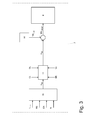
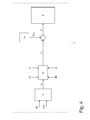
figures 2-4 are three block charts which show respective control logics implemented in the electronic control unit infigure 1 ; and -
figure 5 is a chart which shows an experimental control map stored in a memory of the electronic control unit infigure 1 . - In
figure 1 ,reference numeral 1 indicates as a whole a road vehicle provided with a thermalinternal combustion engine 2 arranged in front position and amanual transmission 3 which transmits the torque generated by thethermal engine 2 to therear drive wheels 4.Transmission 3 comprises a clutch 5 arranged in front position in a bell integral with the engine crankcase and a gearbox 6 arranged in rear position at therear drive wheels 4. - The
internal combustion engine 2 is controlled by anelectronic control unit 7, which inter alia governs the number of rotations per minute of theinternal combustion engine 1. Theelectronic control unit 7 detects the position of the accelerator pedal GA, the position of the brake pedal BR, the position of a clutch pedal CL, and the position of a gear control GE (as thetransmission 3 is manual, clutch 5 is directly controlled by the driver by means of the clutch pedal CL and gearbox 6 is directly controlled by the driver by means of the gear control GE). - As shown in
figure 2 , thecalculation block 8 of theelectronic control unit 7 determines an idle number of rotations per minute NIDLE (i.e. the rotation speed that theinternal combustion engine 2 should maintain when it is under idling conditions) in a known manner (e.g. by reading the value in a memory cell). When theinternal combustion engine 2 is under idling conditions, the idle number of rotations per minute NIDLE becomes the target number of rotations per minute NTARGET which is supplied to aregulator 9 which controls theinternal combustion engine 2 in a known manner to follow the target number of rotations per minute NTARGET (and thus to ensure that the actual number of rotations per minute N is not lower than the idle number of rotations per minute NIDLE, and in particular that the actual number of rotations per minute N is in the surround of the idle number of rotations per minute NIDLE) . - Furthermore, a
calculation block 10 of theelectronic control unit 7 determines a takeoff increase ΔN-1 of the number of rotations per minute, while acalculation block 11 recognizes the beginning of a takeoff phase ofvehicle 1; when the beginning of the takeoff phase ofvehicle 1 is recognized, thecalculation block 11 authorizes adding the takeoff increase ΔN-1 to the idle number of rotations per minute NIDLE, so that the target number of rotations per minute NTARGET which is followed by theregulator 9 is equal to the sum of the idle number of rotations per minute NIDLE and the takeoff increase ΔN-1. In other words, theelectronic control unit 7 controls theinternal combustion engine 2, when the beginning of the takeoff phase ofvehicle 1 is recognized, so that the actual number of rotations per minute N is in the surround of the idle number of rotations per minute NIDLE increased by the takeoff increase ΔN-1. - The
calculation block 10 determines the extent of the takeoff increase ΔN-1 as a function of the temperature TH2O of a cooling liquid of theinternal combustion engine 2, as a function of a gradient RS of the stretch of road on whichvehicle 1 runs, and as a function of an A/D use of a compressor of an air-conditioning system. According to a preferred embodiment, thecalculation block 10 uses an experimental (i.e. determined experimentally) control map to determine the takeoff increase ΔN-1 as a function of the temperature TH2O of the cooling liquid and as a function of the gradient RS of the stretch of road on whichvehicle 1 runs; an example of such an experimental control map is shown infigure 5 . Instead, the fact that the compressor of the air-conditioning system is used or not normally determines a fixed increase which is added to the increase determined by the experimental control map, if needed. The extent of the first takeoff increase ΔN-1 increases as the temperature TH2O of the cooling liquid decreases, increases as the gradient RS of the stretch of road on whichvehicle 1 runs increases, and increases when the compressor of the air-conditioning system is used. - It is worth noting that the gradient RS of the stretch of road on which
vehicle 1 runs may be zero (flat road), positive (uphill road), or negative (downhill road); when the gradient RS is positive (uphill road), the takeoff increase ΔN-1 rises because a component of the gravity force must also be overcome in order to move thevehicle 1, while when the gradient RS is negative (downhill road), the takeoff increase ΔN-1 decreases and may be even cancelled out because a component of the force of gravity pushes to move thevehicle 1. The dependence on the gradient RS of the stretch of road on whichvehicle 1 runs is very important because it allows to increase the number of rotations per minute proportionally to how steep the gradient is, while allowing not to increase the number of rotations per minute in downhill circumstances when not required, or it could even be dangerous becausevehicle 1 could unexpectedly accelerate. The gradient RS of the stretch of road on whichvehicle 1 runs is determined in a known manner either by means of a specific sensor or by means of an estimation algorithm based on information supplied by the accelerometers normally present in modern vehicles (e.g. the accelerometers used in "ESP" stability control system). - By way of example, the takeoff increase ΔN-1 has an order of magnitude of 200-400 rpm when the gradient RS of the stretch of road on which
vehicle 1 runs is zero, may be zero when the gradient RS of the strength of road on whichvehicle 1 runs is negative (downhill road), and may reach even 600-800 rpm when the gradient RS of the stretch of road on whichvehicle 1 runs is positive (uphill road). - The
calculation block 11 recognizes the beginning of the takeoff phase when the driver ofvehicle 1 manifests the will to take off, i.e. when the clutch 5 is open (that is when the clutch pedal CL is pressed) and a gear is engaged in a gearbox 6 (that is when the gear control GE determines the engagement of a gear in the gearbox 6). According to an alternative embodiment, thecalculation block 11 recognizes the beginning of the takeoff phase ofvehicle 1 only when the clutch pedal CL starts being released in the absence of torque transmission through the clutch 5 and a gear is engaged in gearbox 6; in other words, the beginning of the takeoff phase is recognized when the driver starts releasing the clutch pedal CL and a gear is engaged in gearbox 6. The increase of number of rotations per minute irrespective of the pressing of the accelerator pedal GA may have a strong impact on the driver (who could observe the increase of number of rotations per minute on the dashboard and/or could hear theinternal combustion engine 1 accelerate), and therefore attempting to increase the number of rotations per minute without the driver clearly perceiving the increase is absolutely needed. By increasing the number of rotations per minute when the driver manifests the will to take off (i.e. presses the clutch pedal CL while engaging a gear in gearbox 6 or starts releasing the clutch CL when a gear is engaged in gearbox 6), the increase of number of rotations per minute determined by the takeoff increase ΔN-1 is deemed "coherent" (i.e. not anomalous) by the driver, as it is consistent with the maneuvers which are being carried out. - As shown in
figure 2 , acalculation block 12 of theelectronic control unit 7 determines a takeoff increase ΔN-2 of the number of rotations per minute, while acalculation block 13 recognizes the starting instant of a coupling of the clutch discs of clutch 5 (i.e. the beginning of the torque transmission through clutch 5); when the starting instant of the coupling of the clutch discs is recognized, thecalculation block 13 authorizes adding the takeoff increase ΔN-2 to the takeoff increase ΔN-1 and to the idle number of rotations per minute NIDLE so that the target number of rotations per minute NTARGET which is followed byregulator 9 is equal to sum of the idle number of rotations per minute NIDLE, the takeoff increase ΔN-1 and the takeoff increase ΔN-2. In other words, theelectronic control unit 7 controls theinternal combustion engine 2, when the starting instant of the coupling of the clutch discs is recognized, so that the actual number of rotations per minute N is in the surround of the idle number of rotations per minute NIDLE increased by the takeoff increase ΔN-1 and by the takeoff increase ΔN-2. - The
calculation block 12 determines the extent of the takeoff increase ΔN-2 as a function of the gradient RS of the stretch of road on whichvehicle 1 runs, as a function of a longitudinal acceleration Ax ofvehicle 1, and as a function of a position of the accelerator pedal GA. In particular, the extent of the takeoff increase ΔN-2 increases as the gradient RS of the stretch of road on whichvehicle 1 runs increases, increases as the longitudinal acceleration Ax ofvehicle 1 increases (the greater the longitudinal acceleration Ax ofvehicle 1, the faster the clutch closing maneuver), and increases as the position of the accelerator pedal GA increases (i.e. it is greater the more the accelerator pedal GA is pressed to go along with a request for greater torque by the driver). According to a preferred embodiment, thecalculation block 12 uses an experimental (i.e. determined experimentally) control map to determine the takeoff increase ΔN-2. - By way of example, the takeoff increase ΔN-2 has an order of magnitude of 100-300 rpm when the gradient RS of the stretch of road on which
vehicle 1 runs is zero; increasing the number of rotations per minute during the step of coupling the clutch discs allows to compensate for the drop in number of rotations per minute which is typical of this phase. In other words, by virtue of the takeoff increase ΔN-2, the typical drop in number of rotations per minute of the step of coupling the clutch discs is compensated, and therefore the driver does not perceive at all the application of the takeoff increase ΔN-2, because the actual number of rotations per minute remains totally constant. - The
calculation block 13 recognizes the starting instant of the coupling of the clutch discs when the longitudinal acceleration Ax ofvehicle 1 increases, i.e. when the longitudinal acceleration Ax ofvehicle 1 which was previously zero (vehicle 1 stationary) exceeds a threshold value. According to an alternative embodiment, thecalculation block 13 recognizes the starting instant of the coupling of the clutch discs when a decrease in the actual number of rotations per minute N and an increase in the longitudinal acceleration Ax ofvehicle 1 occur simultaneously. - The determined increase of the number of rotations per minute of both the takeoff increase ΔN-1 and the takeoff increase ΔN-2 allows to increase the torque generated by the
internal combustion engine 1 and thus allows a torque adapted to move thevehicle 1, even in the absence of a correct pressing of the accelerator pedal GA by the driver, to be available. - As shown in
figure 3 , thecalculation block 14 of theelectronic control unit 7 determines an idle torque reserve TRIDLE (i.e. the torque reserve that theinternal combustion engine 2 should maintain when it is under idling conditions) in a known manner (e.g. by reading the value in a memory cell). When theinternal combustion engine 2 is under idling conditions, the idle torque reserve TRIDLE becomes the target torque reserve TRTARGET which is supplied to theregulator 9 which controls theinternal combustion engine 2 in a known manner in order to follow the target torque reserve TRTARGET (so that the actual torque reserve TR is not lower than the idle torque reserve TRIDLE, and in particular the actual torque reserve TR is in the surround of an idle torque reserve TRIDLE). - Furthermore, a
calculation block 15 of theelectronic control unit 7 determines a takeoff torque reserve increase ΔTR, while thecalculation block 11 recognizes the beginning of the takeoff phase of vehicle 1 (as described above); when the beginning of the takeoff phase ofvehicle 1 is recognized, thecalculation block 11 authorizes adding the takeoff increase ΔTR to the idle torque reserve TRIDLE, so that the target torque reserve TRTARGET which is followed by theregulator 9 is equal to the sum of the idle torque reserve TRIDLE and the takeoff increase ΔTR. In other words, when the beginning of the takeoff phase ofvehicle 1 is recognized, theelectronic control unit 7 controls theinternal combustion engine 2 so that the actual torque reserve is not lower than the idle torque reserve TRIDLE increased by the takeoff increase ΔN-1. - The
calculation block 15 determines the extent of the takeoff increase ΔTR as a function of the temperature TH2O of the cooling liquid of theinternal combustion engine 2, as a function of the gradient RS of the stretch of road on whichvehicle 1 runs, as a function of the position of the accelerator pedal GA, and as a function of the actual number of rotations per minute N. According to a preferred embodiment, thecalculation block 15 uses an experimental (i.e. determined experimentally) control map to determine the takeoff increase ΔTR. The extent of the takeoff increase ΔTR increases as the temperature TH2O of the cooling liquid decreases, increases as the gradient RS of the stretch of road on whichvehicle 1 runs increases, decreases (until it is cancelled out) as the position of the accelerator pedal GA increases (in particular, the extent of the takeoff increase ΔTR normally has a "humpback" shape, and is normally reduced to zero as the position of the accelerator pedal GA increases), and increases as the actual number of rotations per minute N decreases. - The increase of the torque reserve TR allows the
electronic control unit 7 to very rapidly increase (i.e. by operating on the spark advance that is already effective at the next combustion) the torque generated by theinternal combustion engine 1 in case of need (i.e. in the absence of a correct pressing of the accelerator pedal GA by the driver). In other words, the increase of torque reserve TR allows theregulator 9 which controls the number of rotations per minute to have a greater authority and to operate more rapidly in case of need (i.e. in the absence of a correct pressing of the accelerator pedal GA by the driver). - As shown in
figure 4 , acalculation block 16 of theelectronic control unit 7 determines idle coefficients KIDLE of theregulator 9 in a known manner (e.g. by reading the value of the memory cell), which regulator controls the number of rotations per minute (e.g. the proportional, derivative and integrative coefficients, if theregulator 9 uses a PID logic); when theinternal combustion engine 2 is under idling conditions, the idle coefficients KIDLE become the K coefficients used byregulator 9. Furthermore, thecalculation block 17 of theelectronic control unit 7 determines a takeoff variation ΔK of the coefficients; when the starting instant of the coupling of the clutch discs is recognized, thecalculation block 13 authorizes varying (i.e. algebraically adding by taking the sign into account) the idle coefficients KIDLE ofregulator 9 by applying the takeoff variation ΔK. In other words, when the starting instant of the coupling of the clutch discs is recognized, theelectronic control unit 7 varies the coefficients KIDLE of theregulator 9 which controls the number of rotations per minute by applying the takeoff variation ΔK. - The
calculation block 17 determines the extent of the takeoff variation ΔK of the coefficients as a function of the gradient RS of the stretch of road on whichvehicle 1 runs, and as a function of a coupling degree %CL of the clutch discs of clutch 5. The coupling degree %CL of the clutch discs is provided, for example, by a ratio of the rotation speed of an output shaft of clutch 5 to the rotation speed of an input shaft of clutch 5. The takeoff variation ΔK determines an increase of the response rapidity of the control carried out by theregulator 9, i.e. makes the control carried out by theregulator 9 "faster". The control response rapidity determined by the takeoff variation ΔK is increased proportionally to the increase of the gradient RS of the stretch of road on whichvehicle 1 runs, and proportionally to the decrease of the degree of coupling %CL of the clutch discs. According to a preferred embodiment, thecalculation block 17 uses an experimental (i.e. determined experimentally) control map to determine the takeoff variation ΔK. - The variation of the idle coefficients KIDLE of
regulator 9 allows theelectronic control unit 7 to react faster in case of a drop of the number of rotations per minute after the coupling of the clutch discs, which drop is determined by the absence of a correct pressing of the accelerator pedal GA by the driver, for example. - According to a preferred embodiment shown in the accompanying drawings, the calculation blocks 11 and 13 of the
electronic control unit 7 recognize the pressing of the brake pedal BR and either reduce or cancel out takeoff increases and variations ΔN-1, ΔN-2, ΔTR, ΔK when the pressing of the brake pedal BR is recognized. In other words, the pressing of the brake pedal BR clearly indicates the driver's will not to start the vehicle 1 (i.e. not to carry out the takeoff phase), and thus when the driver presses the brake pedal BR, then all the contrivances to improve the takeoff phase (takeoff increases and variations ΔN-1, ΔN-2, ΔTR. ΔK) are first reduced and then cancelled out. - According to a preferred embodiment, the calculation blocks 11 and 13 of the
electronic control unit 7 recognize the end of the takeoff phase ofvehicle 1 and therefore gradually cancel out the takeoff increases and variations ΔN-1, ΔN-2, ΔTR, ΔK at the end of the takeoff phase. The calculation blocks 11 and 13 of theelectronic control unit 7 preferably recognize the end of the takeoff phase ofvehicle 1 when a longitudinal speed Vx ofvehicle 1 exceeds a threshold value (generally equal to 5-10 km/h). - The above-described method for controlling the number of rotations per minute of an
internal combustion engine 2 during a takeoff phase has many advantages. - Firstly, the above-described method for controlling the number of rotations per minute is simple and cost-effective to be implemented in an electronic control unit of a modern generation internal combustion engine, because it only uses measurements supplied by sensors which are always present in modern internal combustion engines (thus no hardware change is needed) and requires neither high calculation capacity nor high memory capacity.
- Furthermore, the above-described method for controlling the number of rotations per minute ensures that the takeoff phase of
vehicle 1 always occurs in an at least satisfactory manner, and in most cases in an optimal manner also when the driver carries out maneuvers incorrectly (e.g. when the clutch pedal C1 is released too quickly or when the accelerator pedal GA is not sufficiently pressed). In other words, the above-described method for controlling the number of rotations per minute implements a regulation of the number of rotations per minute which supports, and when required compensates for (also with torque corrections), the driver's maneuvers thus allowing to perform the takeoff phase in an at least satisfactory manner also when the driver carries out the maneuvers incorrectly. - Finally, the above-described method for controlling the number of rotations per minute increases, when needed, the number of rotations per minute in a substantially transparent manner for the driver, i.e. without the driver perceiving an "anomalous" increase of the number of rotations per minute (i.e. an increase of the number of rotations per minute not justified by the commands imparted by the driver).
Claims (16)
- A method for controlling the number of revolutions per minute of an internal combustion engine (2) during a takeoff phase of a vehicle (1) provided with a manual transmission (3); the control method comprises the steps of:determining an idle number of revolutions per minute (NIDLE);controlling the internal combustion engine (2), so that the actual number of rotations per minute (N) is not lower than the idle number of revolutions per minute (NIDLE);recognizing the beginning of a takeoff phase of the vehicle (1);establishing a first takeoff increase (ΔN-1) of the number of revolutions per minute; andcontrolling, when the beginning of the takeoff phase of the vehicle (1) is recognized, the internal combustion engine (2), so that the actual number of rotations per minute (N) is not lower than the idle number of revolutions per minute (NIDLE) increased by the first takeoff increase (ΔN-1);the control method is characterized in that it comprises the further step of determining the extent of the first takeoff increase (ΔN-1) as a function of the temperature (TH2O) of a cooling liquid of the internal combustion engine (2), and/or as a function of a gradient (RS) of the stretch of road on which the vehicle runs (1), and/or as a function of a use of a compressor of an air-conditioning system.
- A control method according to claim 1, wherein the extent of the first takeoff increase (ΔN-1) increases when the temperature (TH2O) of the cooling liquid decreases, increases when the gradient (RS) of the stretch of road on which the vehicle (1) runs increases, and increases when the compressor of the air-conditioning system is used.
- A control method according to claim 1 or 2, wherein the beginning of the takeoff phase is recognized when the driver of the vehicle (1) manifests the will to take off.
- A control method according to claim 3, wherein the beginning of the takeoff phase is recognized when a clutch (5) of the transmission (3) is open and a gear is engaged in a gearbox (6) of the transmission (3).
- A control method according to claim 3, wherein the beginning of the takeoff phase of the vehicle (1) is recognized when a clutch pedal (CL) starts being released in absence of a torque transmission through a clutch (5) of the transmission (3) and a gear is engaged in a gearbox (6) of the transmission (3).
- A control method according to any of the claims from 1 to 5 and comprising the further steps of:recognizing the starting instant of a coupling of the clutch discs of a clutch (5) of the transmission (3) ;establishing a second takeoff increase (ΔN-2) of the number of revolutions per minute;controlling, when the starting instant of the coupling of the clutch discs is recognized, the internal combustion engine (2), so that the actual number of rotations per minute (N) is not lower than the idle number of revolutions per minute (NIDLE) increased by the first takeoff increase (ΔN-1) and by the second takeoff increase (ΔN-2).
- A control method according to claim 6, wherein the starting instant of the coupling of the clutch discs is recognized when an increase in the longitudinal acceleration (Ax) of the vehicle (1) takes place.
- A control method according to claim 6, wherein the starting instant of the coupling of the clutch discs is recognized when a decrease in the actual number of rotations per minute (N) and an increase in the longitudinal acceleration (Ax) of the vehicle (1) simultaneously take place.
- A control method according to claim 6, 7 or 8, wherein the extent of the second takeoff increase (ΔN-2) is determined as a function of a gradient (RS) of the stretch of road on which the vehicle runs (1), and/or as a function of a longitudinal acceleration (Ax) of the vehicle (1), and/or as a function of a position of the accelerator pedal (GA).
- A control method according to claim 9, wherein the extent of the second takeoff increase (ΔN-2) increases when the gradient (RS) of the stretch of road on which the vehicle (1) runs increases, increases when the longitudinal acceleration (Ax) of the vehicle (1) increases, and increases when the position of the accelerator pedal (GA) increases.
- A control method according to any of the claims from 1 to 10 and comprising the further steps of:determining an idle torque reserve (TRIDLE);establishing a third takeoff increase (ΔTR) of the number of revolutions per minute;controlling, when the beginning of the takeoff phase of the vehicle (1) is recognized, the internal combustion engine (2), so that the actual torque reserve is not lower than the idle torque reserve (TRIDLE) increased by the third takeoff increase (ΔTR).
- A control method according to claim 11, wherein the extent of the third takeoff increase (ΔTR) is determined as a function of the temperature (TH2O) of a cooling liquid of the internal combustion engine (2), and/or as a function of a gradient (RS) of the stretch of road on which the vehicle (1) runs, and/or as a function of a position of the accelerator pedal (GA), and/or as a function of the actual number of rotations per minute (N).
- A control method according to claim 12, wherein the extent of the third takeoff increase (ΔTR) increases when the temperature (TH2O) of the cooling liquid decreases, increases when the gradient (RS) of the stretch of road on which the vehicle (1) runs increases, decreases when the position of the accelerator pedal (GA) increases, and increases when the actual number of rotations per minute (N) decreases.
- A control method according to any of the claims from 1 to 13 and comprising the further steps of:determining coefficients (KIDLE) of at least one regulator (9), which controls the number of revolutions per minute;recognizing the starting instant of a coupling of the clutch discs of a clutch (5) of the transmission (3) ;establishing a takeoff variation (ΔK) of the coefficients; andvarying, when the starting instant of the coupling of the clutch discs is recognized, the coefficients (KIDLE) of the regulator (9) controlling the number of revolutions per minute by applying the takeoff variation (ΔK).
- A control method according to claim 14, wherein the extent of the takeoff variation (ΔK) of the coefficients is determined as a function of a gradient (RS) of the stretch of road on which the vehicle (1) runs, and/or as a function of a coupling degree (%CL) of the clutch discs.
- A control method according to claim 15, wherein the coupling degree (%CL) of the clutch discs is provided by a ratio between the rotation speed of an output shaft of the clutch (5) and the rotation speed of an input shaft of the clutch (5).
Applications Claiming Priority (1)
| Application Number | Priority Date | Filing Date | Title |
|---|---|---|---|
| IT000214A ITBO20110214A1 (en) | 2011-04-20 | 2011-04-20 | METHOD OF CHECKING THE ROTATION MODE OF AN INTERNAL COMBUSTION ENGINE DURING A DRIVING PHASE OF A VEHICLE PROVIDED WITH A MANUAL TRANSMISSION |
Publications (2)
| Publication Number | Publication Date |
|---|---|
| EP2514950A1 true EP2514950A1 (en) | 2012-10-24 |
| EP2514950B1 EP2514950B1 (en) | 2015-02-18 |
Family
ID=44554059
Family Applications (1)
| Application Number | Title | Priority Date | Filing Date |
|---|---|---|---|
| EP12165068.3A Active EP2514950B1 (en) | 2011-04-20 | 2012-04-20 | Method for controlling the number of rotations per minute of an internal combustion engine during a takeoff phase of a vehicle provided with a manual transmission |
Country Status (4)
| Country | Link |
|---|---|
| EP (1) | EP2514950B1 (en) |
| CN (1) | CN102748148B (en) |
| BR (1) | BR102012009438B8 (en) |
| IT (1) | ITBO20110214A1 (en) |
Cited By (2)
| Publication number | Priority date | Publication date | Assignee | Title |
|---|---|---|---|---|
| FR3016847A1 (en) * | 2014-01-30 | 2015-07-31 | Peugeot Citroen Automobiles Sa | METHOD AND APPARATUS FOR DETECTING A VEHICLE-LIFT LEAK TAKING-UP IN ACCORDANCE WITH THE INJUNCTION OF THE CLUTCH PEDAL FOR TAKE-OFF AID |
| IT202000003098A1 (en) * | 2020-02-17 | 2021-08-17 | Texa Spa | CONTROL SYSTEM AND METHOD FOR ENDOTHERMAL, ELECTRIC AND / OR HYBRID PROPULSION VEHICLES WITH AUTOMATIC TRANSMISSION |
Citations (4)
| Publication number | Priority date | Publication date | Assignee | Title |
|---|---|---|---|---|
| DE4140328A1 (en) * | 1991-12-06 | 1993-06-09 | Bayerische Motoren Werke Ag | Equipment improving starting of motor vehicle - has clutch sensor warning engine control unit about imminent engagement, increasing idle speed and air flow. |
| EP0930424A2 (en) | 1998-01-15 | 1999-07-21 | Volkswagen Aktiengesellschaft | Method and apparatus for improving startoff in a vehicle equipped with a manual gearbox |
| EP1455073A1 (en) * | 2003-03-07 | 2004-09-08 | Toyota Jidosha Kabushiki Kaisha | Output control apparatus of internal combustion engine |
| DE102007001838A1 (en) * | 2007-01-12 | 2008-07-17 | Ford Global Technologies, LLC, Dearborn | Motor vehicle's drive chain controlling method, involves activating speed control mode independent of presence of pedal actuation, when starting condition of vehicle is determined while engine is driven in another speed control mode |
Family Cites Families (1)
| Publication number | Priority date | Publication date | Assignee | Title |
|---|---|---|---|---|
| KR100569400B1 (en) * | 2003-10-27 | 2006-04-07 | 현대자동차주식회사 | How to control fuel injection of Elpia engine |
-
2011
- 2011-04-20 IT IT000214A patent/ITBO20110214A1/en unknown
-
2012
- 2012-04-19 CN CN201210116982.1A patent/CN102748148B/en active Active
- 2012-04-20 BR BR102012009438A patent/BR102012009438B8/en active IP Right Grant
- 2012-04-20 EP EP12165068.3A patent/EP2514950B1/en active Active
Patent Citations (4)
| Publication number | Priority date | Publication date | Assignee | Title |
|---|---|---|---|---|
| DE4140328A1 (en) * | 1991-12-06 | 1993-06-09 | Bayerische Motoren Werke Ag | Equipment improving starting of motor vehicle - has clutch sensor warning engine control unit about imminent engagement, increasing idle speed and air flow. |
| EP0930424A2 (en) | 1998-01-15 | 1999-07-21 | Volkswagen Aktiengesellschaft | Method and apparatus for improving startoff in a vehicle equipped with a manual gearbox |
| EP1455073A1 (en) * | 2003-03-07 | 2004-09-08 | Toyota Jidosha Kabushiki Kaisha | Output control apparatus of internal combustion engine |
| DE102007001838A1 (en) * | 2007-01-12 | 2008-07-17 | Ford Global Technologies, LLC, Dearborn | Motor vehicle's drive chain controlling method, involves activating speed control mode independent of presence of pedal actuation, when starting condition of vehicle is determined while engine is driven in another speed control mode |
Cited By (4)
| Publication number | Priority date | Publication date | Assignee | Title |
|---|---|---|---|---|
| FR3016847A1 (en) * | 2014-01-30 | 2015-07-31 | Peugeot Citroen Automobiles Sa | METHOD AND APPARATUS FOR DETECTING A VEHICLE-LIFT LEAK TAKING-UP IN ACCORDANCE WITH THE INJUNCTION OF THE CLUTCH PEDAL FOR TAKE-OFF AID |
| IT202000003098A1 (en) * | 2020-02-17 | 2021-08-17 | Texa Spa | CONTROL SYSTEM AND METHOD FOR ENDOTHERMAL, ELECTRIC AND / OR HYBRID PROPULSION VEHICLES WITH AUTOMATIC TRANSMISSION |
| EP3865364A1 (en) * | 2020-02-17 | 2021-08-18 | Texa S.p.A. | Control system for combustion, electric and/or hybrid vehicles with automatic transmission |
| CN113335260A (en) * | 2020-02-17 | 2021-09-03 | 泰克萨股份公司 | Control system for a combustion, electric and/or hybrid vehicle having an automatic transmission and method thereof |
Also Published As
| Publication number | Publication date |
|---|---|
| BR102012009438B1 (en) | 2020-11-24 |
| CN102748148A (en) | 2012-10-24 |
| CN102748148B (en) | 2016-06-08 |
| BR102012009438B8 (en) | 2021-05-04 |
| ITBO20110214A1 (en) | 2012-10-21 |
| EP2514950B1 (en) | 2015-02-18 |
| BR102012009438A2 (en) | 2018-03-20 |
Similar Documents
| Publication | Publication Date | Title |
|---|---|---|
| US12017651B2 (en) | Control of a vehicle traction motor torque while vehicle roll-back is inhibited | |
| US8175785B2 (en) | System and method for performance launch control of a vehicle | |
| CN108569294B (en) | Method and system for improving hybrid vehicle transmission shifting | |
| US8768547B2 (en) | Control of a hybrid vehicle with a manual transmission | |
| US20170226947A1 (en) | Vehicle Control Device and Vehicle Control Method | |
| US8560186B2 (en) | Method for identifying a driving resistance of a motor vehicle | |
| US20190176797A1 (en) | Vehicle Control Device | |
| US20170361830A1 (en) | Shifting control method for hybrid vehicle | |
| US10941723B2 (en) | Controller for controlling an engine of a vehicle | |
| US20120184407A1 (en) | Method and means for controlling the downshifting | |
| EP2514950B1 (en) | Method for controlling the number of rotations per minute of an internal combustion engine during a takeoff phase of a vehicle provided with a manual transmission | |
| US11247559B2 (en) | Method for operating a motor vehicle, in particular a truck, and motor vehicle | |
| CN118722600B (en) | Vehicle speed control methods, devices, equipment, storage media and program products | |
| US12576847B2 (en) | Method and control arrangement for controlling a vehicle during a downhill start | |
| SE0901183A1 (en) | Method and system for opening coupling | |
| DE102010021718A1 (en) | Motor vehicle with creeping device | |
| US11370291B2 (en) | Method and system for gear shifting in a hybrid powertrain | |
| JP2015081031A (en) | Power transmission device and control device for power transmission device | |
| JP2011226640A (en) | Control method of drive train of automobile having automatic clutch | |
| US12025192B2 (en) | Mobile body and mobile body control method | |
| EP2508739A1 (en) | A method for the assistance of a motor vehicle driver during a drive off maneuver | |
| US11378024B2 (en) | Internal combustion engine control method and internal combustion engine control device | |
| JP7735757B2 (en) | Vehicle control device | |
| JP2008267587A (en) | Vehicle braking / driving force control apparatus and vehicle braking / driving force control method | |
| JP6076754B2 (en) | Internal combustion engine control device |
Legal Events
| Date | Code | Title | Description |
|---|---|---|---|
| PUAI | Public reference made under article 153(3) epc to a published international application that has entered the european phase |
Free format text: ORIGINAL CODE: 0009012 |
|
| AK | Designated contracting states |
Kind code of ref document: A1 Designated state(s): AL AT BE BG CH CY CZ DE DK EE ES FI FR GB GR HR HU IE IS IT LI LT LU LV MC MK MT NL NO PL PT RO RS SE SI SK SM TR |
|
| AX | Request for extension of the european patent |
Extension state: BA ME |
|
| 17P | Request for examination filed |
Effective date: 20121213 |
|
| GRAP | Despatch of communication of intention to grant a patent |
Free format text: ORIGINAL CODE: EPIDOSNIGR1 |
|
| INTG | Intention to grant announced |
Effective date: 20140221 |
|
| GRAS | Grant fee paid |
Free format text: ORIGINAL CODE: EPIDOSNIGR3 |
|
| GRAJ | Information related to disapproval of communication of intention to grant by the applicant or resumption of examination proceedings by the epo deleted |
Free format text: ORIGINAL CODE: EPIDOSDIGR1 |
|
| GRAP | Despatch of communication of intention to grant a patent |
Free format text: ORIGINAL CODE: EPIDOSNIGR1 |
|
| GRAS | Grant fee paid |
Free format text: ORIGINAL CODE: EPIDOSNIGR3 |
|
| GRAP | Despatch of communication of intention to grant a patent |
Free format text: ORIGINAL CODE: EPIDOSNIGR1 |
|
| GRAJ | Information related to disapproval of communication of intention to grant by the applicant or resumption of examination proceedings by the epo deleted |
Free format text: ORIGINAL CODE: EPIDOSDIGR1 |
|
| GRAL | Information related to payment of fee for publishing/printing deleted |
Free format text: ORIGINAL CODE: EPIDOSDIGR3 |
|
| GRAP | Despatch of communication of intention to grant a patent |
Free format text: ORIGINAL CODE: EPIDOSNIGR1 |
|
| INTC | Intention to grant announced (deleted) | ||
| GRAJ | Information related to disapproval of communication of intention to grant by the applicant or resumption of examination proceedings by the epo deleted |
Free format text: ORIGINAL CODE: EPIDOSDIGR1 |
|
| GRAP | Despatch of communication of intention to grant a patent |
Free format text: ORIGINAL CODE: EPIDOSNIGR1 |
|
| INTG | Intention to grant announced |
Effective date: 20150107 |
|
| GRAA | (expected) grant |
Free format text: ORIGINAL CODE: 0009210 |
|
| AK | Designated contracting states |
Kind code of ref document: B1 Designated state(s): AL AT BE BG CH CY CZ DE DK EE ES FI FR GB GR HR HU IE IS IT LI LT LU LV MC MK MT NL NO PL PT RO RS SE SI SK SM TR |
|
| INTG | Intention to grant announced |
Effective date: 20150107 |
|
| REG | Reference to a national code |
Ref country code: GB Ref legal event code: FG4D |
|
| INTG | Intention to grant announced |
Effective date: 20150107 |
|
| REG | Reference to a national code |
Ref country code: CH Ref legal event code: EP |
|
| REG | Reference to a national code |
Ref country code: AT Ref legal event code: REF Ref document number: 710770 Country of ref document: AT Kind code of ref document: T Effective date: 20150315 |
|
| REG | Reference to a national code |
Ref country code: IE Ref legal event code: FG4D |
|
| REG | Reference to a national code |
Ref country code: DE Ref legal event code: R096 Ref document number: 602012005261 Country of ref document: DE Effective date: 20150402 |
|
| REG | Reference to a national code |
Ref country code: NL Ref legal event code: VDEP Effective date: 20150218 |
|
| REG | Reference to a national code |
Ref country code: AT Ref legal event code: MK05 Ref document number: 710770 Country of ref document: AT Kind code of ref document: T Effective date: 20150218 |
|
| REG | Reference to a national code |
Ref country code: LT Ref legal event code: MG4D |
|
| PG25 | Lapsed in a contracting state [announced via postgrant information from national office to epo] |
Ref country code: SE Free format text: LAPSE BECAUSE OF FAILURE TO SUBMIT A TRANSLATION OF THE DESCRIPTION OR TO PAY THE FEE WITHIN THE PRESCRIBED TIME-LIMIT Effective date: 20150218 Ref country code: FI Free format text: LAPSE BECAUSE OF FAILURE TO SUBMIT A TRANSLATION OF THE DESCRIPTION OR TO PAY THE FEE WITHIN THE PRESCRIBED TIME-LIMIT Effective date: 20150218 Ref country code: LT Free format text: LAPSE BECAUSE OF FAILURE TO SUBMIT A TRANSLATION OF THE DESCRIPTION OR TO PAY THE FEE WITHIN THE PRESCRIBED TIME-LIMIT Effective date: 20150218 Ref country code: NO Free format text: LAPSE BECAUSE OF FAILURE TO SUBMIT A TRANSLATION OF THE DESCRIPTION OR TO PAY THE FEE WITHIN THE PRESCRIBED TIME-LIMIT Effective date: 20150518 Ref country code: HR Free format text: LAPSE BECAUSE OF FAILURE TO SUBMIT A TRANSLATION OF THE DESCRIPTION OR TO PAY THE FEE WITHIN THE PRESCRIBED TIME-LIMIT Effective date: 20150218 Ref country code: ES Free format text: LAPSE BECAUSE OF FAILURE TO SUBMIT A TRANSLATION OF THE DESCRIPTION OR TO PAY THE FEE WITHIN THE PRESCRIBED TIME-LIMIT Effective date: 20150218 |
|
| PG25 | Lapsed in a contracting state [announced via postgrant information from national office to epo] |
Ref country code: GR Free format text: LAPSE BECAUSE OF FAILURE TO SUBMIT A TRANSLATION OF THE DESCRIPTION OR TO PAY THE FEE WITHIN THE PRESCRIBED TIME-LIMIT Effective date: 20150519 Ref country code: AT Free format text: LAPSE BECAUSE OF FAILURE TO SUBMIT A TRANSLATION OF THE DESCRIPTION OR TO PAY THE FEE WITHIN THE PRESCRIBED TIME-LIMIT Effective date: 20150218 Ref country code: RS Free format text: LAPSE BECAUSE OF FAILURE TO SUBMIT A TRANSLATION OF THE DESCRIPTION OR TO PAY THE FEE WITHIN THE PRESCRIBED TIME-LIMIT Effective date: 20150218 Ref country code: IS Free format text: LAPSE BECAUSE OF FAILURE TO SUBMIT A TRANSLATION OF THE DESCRIPTION OR TO PAY THE FEE WITHIN THE PRESCRIBED TIME-LIMIT Effective date: 20150618 Ref country code: LV Free format text: LAPSE BECAUSE OF FAILURE TO SUBMIT A TRANSLATION OF THE DESCRIPTION OR TO PAY THE FEE WITHIN THE PRESCRIBED TIME-LIMIT Effective date: 20150218 Ref country code: NL Free format text: LAPSE BECAUSE OF FAILURE TO SUBMIT A TRANSLATION OF THE DESCRIPTION OR TO PAY THE FEE WITHIN THE PRESCRIBED TIME-LIMIT Effective date: 20150218 |
|
| PG25 | Lapsed in a contracting state [announced via postgrant information from national office to epo] |
Ref country code: CZ Free format text: LAPSE BECAUSE OF FAILURE TO SUBMIT A TRANSLATION OF THE DESCRIPTION OR TO PAY THE FEE WITHIN THE PRESCRIBED TIME-LIMIT Effective date: 20150218 Ref country code: DK Free format text: LAPSE BECAUSE OF FAILURE TO SUBMIT A TRANSLATION OF THE DESCRIPTION OR TO PAY THE FEE WITHIN THE PRESCRIBED TIME-LIMIT Effective date: 20150218 Ref country code: EE Free format text: LAPSE BECAUSE OF FAILURE TO SUBMIT A TRANSLATION OF THE DESCRIPTION OR TO PAY THE FEE WITHIN THE PRESCRIBED TIME-LIMIT Effective date: 20150218 Ref country code: SK Free format text: LAPSE BECAUSE OF FAILURE TO SUBMIT A TRANSLATION OF THE DESCRIPTION OR TO PAY THE FEE WITHIN THE PRESCRIBED TIME-LIMIT Effective date: 20150218 Ref country code: RO Free format text: LAPSE BECAUSE OF FAILURE TO SUBMIT A TRANSLATION OF THE DESCRIPTION OR TO PAY THE FEE WITHIN THE PRESCRIBED TIME-LIMIT Effective date: 20150218 |
|
| REG | Reference to a national code |
Ref country code: DE Ref legal event code: R097 Ref document number: 602012005261 Country of ref document: DE |
|
| PG25 | Lapsed in a contracting state [announced via postgrant information from national office to epo] |
Ref country code: LU Free format text: LAPSE BECAUSE OF FAILURE TO SUBMIT A TRANSLATION OF THE DESCRIPTION OR TO PAY THE FEE WITHIN THE PRESCRIBED TIME-LIMIT Effective date: 20150420 Ref country code: MC Free format text: LAPSE BECAUSE OF FAILURE TO SUBMIT A TRANSLATION OF THE DESCRIPTION OR TO PAY THE FEE WITHIN THE PRESCRIBED TIME-LIMIT Effective date: 20150218 Ref country code: PL Free format text: LAPSE BECAUSE OF FAILURE TO SUBMIT A TRANSLATION OF THE DESCRIPTION OR TO PAY THE FEE WITHIN THE PRESCRIBED TIME-LIMIT Effective date: 20150218 |
|
| REG | Reference to a national code |
Ref country code: CH Ref legal event code: PL |
|
| PLBE | No opposition filed within time limit |
Free format text: ORIGINAL CODE: 0009261 |
|
| STAA | Information on the status of an ep patent application or granted ep patent |
Free format text: STATUS: NO OPPOSITION FILED WITHIN TIME LIMIT |
|
| 26N | No opposition filed |
Effective date: 20151119 |
|
| REG | Reference to a national code |
Ref country code: IE Ref legal event code: MM4A |
|
| PG25 | Lapsed in a contracting state [announced via postgrant information from national office to epo] |
Ref country code: CH Free format text: LAPSE BECAUSE OF NON-PAYMENT OF DUE FEES Effective date: 20150430 Ref country code: LI Free format text: LAPSE BECAUSE OF NON-PAYMENT OF DUE FEES Effective date: 20150430 |
|
| PG25 | Lapsed in a contracting state [announced via postgrant information from national office to epo] |
Ref country code: SI Free format text: LAPSE BECAUSE OF FAILURE TO SUBMIT A TRANSLATION OF THE DESCRIPTION OR TO PAY THE FEE WITHIN THE PRESCRIBED TIME-LIMIT Effective date: 20150218 |
|
| REG | Reference to a national code |
Ref country code: FR Ref legal event code: PLFP Year of fee payment: 5 |
|
| PG25 | Lapsed in a contracting state [announced via postgrant information from national office to epo] |
Ref country code: IE Free format text: LAPSE BECAUSE OF NON-PAYMENT OF DUE FEES Effective date: 20150420 |
|
| PG25 | Lapsed in a contracting state [announced via postgrant information from national office to epo] |
Ref country code: BE Free format text: LAPSE BECAUSE OF FAILURE TO SUBMIT A TRANSLATION OF THE DESCRIPTION OR TO PAY THE FEE WITHIN THE PRESCRIBED TIME-LIMIT Effective date: 20150218 |
|
| GBPC | Gb: european patent ceased through non-payment of renewal fee |
Effective date: 20160420 |
|
| PG25 | Lapsed in a contracting state [announced via postgrant information from national office to epo] |
Ref country code: MT Free format text: LAPSE BECAUSE OF FAILURE TO SUBMIT A TRANSLATION OF THE DESCRIPTION OR TO PAY THE FEE WITHIN THE PRESCRIBED TIME-LIMIT Effective date: 20150218 |
|
| PG25 | Lapsed in a contracting state [announced via postgrant information from national office to epo] |
Ref country code: GB Free format text: LAPSE BECAUSE OF NON-PAYMENT OF DUE FEES Effective date: 20160420 |
|
| REG | Reference to a national code |
Ref country code: FR Ref legal event code: PLFP Year of fee payment: 6 |
|
| PG25 | Lapsed in a contracting state [announced via postgrant information from national office to epo] |
Ref country code: HU Free format text: LAPSE BECAUSE OF FAILURE TO SUBMIT A TRANSLATION OF THE DESCRIPTION OR TO PAY THE FEE WITHIN THE PRESCRIBED TIME-LIMIT; INVALID AB INITIO Effective date: 20120420 Ref country code: SM Free format text: LAPSE BECAUSE OF FAILURE TO SUBMIT A TRANSLATION OF THE DESCRIPTION OR TO PAY THE FEE WITHIN THE PRESCRIBED TIME-LIMIT Effective date: 20150218 Ref country code: BG Free format text: LAPSE BECAUSE OF FAILURE TO SUBMIT A TRANSLATION OF THE DESCRIPTION OR TO PAY THE FEE WITHIN THE PRESCRIBED TIME-LIMIT Effective date: 20150218 |
|
| PG25 | Lapsed in a contracting state [announced via postgrant information from national office to epo] |
Ref country code: CY Free format text: LAPSE BECAUSE OF FAILURE TO SUBMIT A TRANSLATION OF THE DESCRIPTION OR TO PAY THE FEE WITHIN THE PRESCRIBED TIME-LIMIT Effective date: 20150218 |
|
| PG25 | Lapsed in a contracting state [announced via postgrant information from national office to epo] |
Ref country code: PT Free format text: LAPSE BECAUSE OF FAILURE TO SUBMIT A TRANSLATION OF THE DESCRIPTION OR TO PAY THE FEE WITHIN THE PRESCRIBED TIME-LIMIT Effective date: 20150618 |
|
| REG | Reference to a national code |
Ref country code: FR Ref legal event code: PLFP Year of fee payment: 7 |
|
| PG25 | Lapsed in a contracting state [announced via postgrant information from national office to epo] |
Ref country code: MK Free format text: LAPSE BECAUSE OF FAILURE TO SUBMIT A TRANSLATION OF THE DESCRIPTION OR TO PAY THE FEE WITHIN THE PRESCRIBED TIME-LIMIT Effective date: 20150218 |
|
| PGFP | Annual fee paid to national office [announced via postgrant information from national office to epo] |
Ref country code: TR Payment date: 20180403 Year of fee payment: 7 |
|
| PG25 | Lapsed in a contracting state [announced via postgrant information from national office to epo] |
Ref country code: AL Free format text: LAPSE BECAUSE OF FAILURE TO SUBMIT A TRANSLATION OF THE DESCRIPTION OR TO PAY THE FEE WITHIN THE PRESCRIBED TIME-LIMIT Effective date: 20150218 |
|
| PG25 | Lapsed in a contracting state [announced via postgrant information from national office to epo] |
Ref country code: TR Free format text: LAPSE BECAUSE OF NON-PAYMENT OF DUE FEES Effective date: 20190420 |
|
| PGFP | Annual fee paid to national office [announced via postgrant information from national office to epo] |
Ref country code: DE Payment date: 20250423 Year of fee payment: 14 |
|
| PGFP | Annual fee paid to national office [announced via postgrant information from national office to epo] |
Ref country code: IT Payment date: 20260319 Year of fee payment: 15 |
|
| PGFP | Annual fee paid to national office [announced via postgrant information from national office to epo] |
Ref country code: FR Payment date: 20260319 Year of fee payment: 15 |