EP2514948A2 - Distributed aircraft engine fuel system - Google Patents
Distributed aircraft engine fuel system Download PDFInfo
- Publication number
- EP2514948A2 EP2514948A2 EP12162775A EP12162775A EP2514948A2 EP 2514948 A2 EP2514948 A2 EP 2514948A2 EP 12162775 A EP12162775 A EP 12162775A EP 12162775 A EP12162775 A EP 12162775A EP 2514948 A2 EP2514948 A2 EP 2514948A2
- Authority
- EP
- European Patent Office
- Prior art keywords
- fuel
- metering module
- stage
- injector
- multistage combustor
- Prior art date
- Legal status (The legal status is an assumption and is not a legal conclusion. Google has not performed a legal analysis and makes no representation as to the accuracy of the status listed.)
- Granted
Links
- 239000000446 fuel Substances 0.000 title claims abstract description 302
- 238000005086 pumping Methods 0.000 claims description 14
- 239000002828 fuel tank Substances 0.000 claims description 10
- 238000006073 displacement reaction Methods 0.000 claims description 8
- 238000000034 method Methods 0.000 claims description 6
- 238000011144 upstream manufacturing Methods 0.000 claims description 5
- 238000005507 spraying Methods 0.000 claims 1
- 239000007921 spray Substances 0.000 description 10
- 238000010586 diagram Methods 0.000 description 8
- 239000003921 oil Substances 0.000 description 3
- 238000012544 monitoring process Methods 0.000 description 2
- 238000002485 combustion reaction Methods 0.000 description 1
- 230000001934 delay Effects 0.000 description 1
- 230000009977 dual effect Effects 0.000 description 1
- 238000010438 heat treatment Methods 0.000 description 1
- 230000003993 interaction Effects 0.000 description 1
- 238000012423 maintenance Methods 0.000 description 1
- 239000000463 material Substances 0.000 description 1
- 238000012986 modification Methods 0.000 description 1
- 230000004048 modification Effects 0.000 description 1
- 239000010705 motor oil Substances 0.000 description 1
- 239000013618 particulate matter Substances 0.000 description 1
Images


Classifications
-
- F—MECHANICAL ENGINEERING; LIGHTING; HEATING; WEAPONS; BLASTING
- F02—COMBUSTION ENGINES; HOT-GAS OR COMBUSTION-PRODUCT ENGINE PLANTS
- F02C—GAS-TURBINE PLANTS; AIR INTAKES FOR JET-PROPULSION PLANTS; CONTROLLING FUEL SUPPLY IN AIR-BREATHING JET-PROPULSION PLANTS
- F02C7/00—Features, components parts, details or accessories, not provided for in, or of interest apart form groups F02C1/00 - F02C6/00; Air intakes for jet-propulsion plants
- F02C7/22—Fuel supply systems
- F02C7/236—Fuel delivery systems comprising two or more pumps
-
- F—MECHANICAL ENGINEERING; LIGHTING; HEATING; WEAPONS; BLASTING
- F02—COMBUSTION ENGINES; HOT-GAS OR COMBUSTION-PRODUCT ENGINE PLANTS
- F02C—GAS-TURBINE PLANTS; AIR INTAKES FOR JET-PROPULSION PLANTS; CONTROLLING FUEL SUPPLY IN AIR-BREATHING JET-PROPULSION PLANTS
- F02C7/00—Features, components parts, details or accessories, not provided for in, or of interest apart form groups F02C1/00 - F02C6/00; Air intakes for jet-propulsion plants
- F02C7/22—Fuel supply systems
- F02C7/228—Dividing fuel between various burners
-
- F—MECHANICAL ENGINEERING; LIGHTING; HEATING; WEAPONS; BLASTING
- F02—COMBUSTION ENGINES; HOT-GAS OR COMBUSTION-PRODUCT ENGINE PLANTS
- F02C—GAS-TURBINE PLANTS; AIR INTAKES FOR JET-PROPULSION PLANTS; CONTROLLING FUEL SUPPLY IN AIR-BREATHING JET-PROPULSION PLANTS
- F02C9/00—Controlling gas-turbine plants; Controlling fuel supply in air- breathing jet-propulsion plants
- F02C9/26—Control of fuel supply
- F02C9/30—Control of fuel supply characterised by variable fuel pump output
-
- F—MECHANICAL ENGINEERING; LIGHTING; HEATING; WEAPONS; BLASTING
- F05—INDEXING SCHEMES RELATING TO ENGINES OR PUMPS IN VARIOUS SUBCLASSES OF CLASSES F01-F04
- F05D—INDEXING SCHEME FOR ASPECTS RELATING TO NON-POSITIVE-DISPLACEMENT MACHINES OR ENGINES, GAS-TURBINES OR JET-PROPULSION PLANTS
- F05D2270/00—Control
- F05D2270/30—Control parameters, e.g. input parameters
- F05D2270/306—Mass flow
-
- F—MECHANICAL ENGINEERING; LIGHTING; HEATING; WEAPONS; BLASTING
- F05—INDEXING SCHEMES RELATING TO ENGINES OR PUMPS IN VARIOUS SUBCLASSES OF CLASSES F01-F04
- F05D—INDEXING SCHEME FOR ASPECTS RELATING TO NON-POSITIVE-DISPLACEMENT MACHINES OR ENGINES, GAS-TURBINES OR JET-PROPULSION PLANTS
- F05D2270/00—Control
- F05D2270/30—Control parameters, e.g. input parameters
- F05D2270/31—Fuel schedule for stage combustors
Definitions
- the present disclosure relates to a fuel system for delivering fuel to a gas turbine engine.
- a typical fuel system includes a large pump driven by a turbine engine through a gearbox.
- the pump is specifically oversized for peak demand.
- the fuel system includes a bypass valve to return unneeded fuel back to the engine fuel inlet or fuel tank, which is inefficient.
- the fuel returned to the tank is hot, which undesirably raises the temperature of fuel in the fuel tank.
- excess pressure is generated that must be relieved by using a pressure relief valve to mitigate any potential burst or over pressure conditions.
- fuel injectors are arranged into operative groups called "stages".
- stages a single engine-driven pump and metering valve feed fuel to a plurality of fuel distribution lines.
- Each fuel distribution line includes a staging valve for modulating fuel flow to a single combustor stage, which includes a plurality of fuel injectors.
- Some fuel systems additionally include temperature sensors proximate the fuel injectors to monitor temperature distribution around the combustor.
- a fuel system for a gas turbine engine having an electronic engine control includes a plurality of fuel injectors grouped by stages in a multistage combustor and at least one fuel metering module per stage of the multistage combustor.
- Each fuel metering module includes a positive displacement pump for pumping fuel, a flow meter for measuring fuel flow, and a first pressure sensor for sensing fuel pressure.
- Each fuel metering module further includes a controller for receiving and analyzing information regarding fuel flow from the flow meter, fuel pressure from the first pressure sensor, and fuel demand from the electronic engine control, as well as an electric motor for driving the positive displacement pump in accordance with a signal received from the controller to modulate fuel output for the fuel metering module.
- a fuel system for a gas turbine engine includes a fuel tank, a boost pump downstream of the fuel tank, a fuel/oil heat exchanger downstream of the boost pump, and a filter downstream of the fuel/oil heat exchanger.
- a multistage combustor is located downstream of the filter and includes fuel injectors located in fuel nozzles and operatively organized into stages.
- a plurality of fuel flow metering modules are located downstream of the filter and upstream of the multistage combustor. The plurality of fuel flow metering modules are configured to control fuel output to one or more fuel injectors in the multistage combustor and operate independently of one another.
- a method for distributing fuel in a gas turbine engine having a fuel requirement includes pumping fuel to at least one fuel injector of a multistage combustor and measuring flow rate of fuel while pumping fuel. The method further includes comparing the measured flow rate of fuel with the gas turbine engine fuel requirement and controlling pumping speed based on the comparison between the measured flow rate of fuel and the gas turbine engine fuel requirement to modulate fuel flowing to the at least one fuel injector of the multistage combustor.
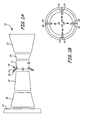
- Fig. 1A is a side schematic view of a turbofan gas turbine engine having a multistage combustor.
- Fig. 1B is a cross section of the multistage combustor from Fig. 1A .
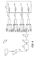
- Fig. 2 is a block diagram showing a first embodiment of a fuel distribution system.
- Fig. 3 is a block diagram showing a single fuel flow metering module from Fig. 2 .
- Fig. 4 is a block diagram showing a second embodiment of the fuel distribution system.
- Fig. 5 is a block diagram showing a third embodiment of the fuel distribution system.
- Fig. 1A is a side schematic view of gas turbine engine 10 having multistage combustor 12, and Fig. 1B is a cross section of multistage combustor 12.
- Gas turbine engine 10 includes fan 14, low pressure compressor (LPC) 16, high pressure compressor (HPC) 18, high pressure turbine (HPT) 20, and low pressure turbine (LPT) 22.
- Multistage combustor 12 includes first stage fuel injectors 24 and second stage fuel injectors 26 located within fuel nozzles 28.
- gas turbine engine 10 is a turbofan engine for powering an aircraft, although the invention is not so limited and can be utilized in any gas turbine engine.
- LPC 16 Located within gas turbine engine 10 and arranged in flow series are fan 14, LPC 16, HPC 18, multistage combustor 12, HPT 20, and LPT 22.
- LPC 16 is mechanically coupled to LPT 22 by a low pressure shaft and HPC 18 is mechanically coupled to HPT 20 by a high pressure shaft.
- air enters a front end of gas turbine engine 10 at fan 14 and is compressed by LPC 16 and HPC 18. The compressed air then enters multistage combustor 12, where it is mixed with fuel and combusted. Combusted air enters HPT 20 and LPT 22 where it is expanded and forces one or both of the turbines to rotate, which drives fan 14, LPC 16 and HPC 18.
- First stage fuel injectors 24 may be physically coupled with second stage fuel injectors 26, such that one first stage fuel injector 24 and one second stage fuel injector 26 form a single fuel nozzle 28.
- a number of fuel nozzles 28 are located around multistage combustor 12.
- the depicted embodiment includes four first stage fuel injectors 24 and four second stage fuel injectors 26 coupled together to form four fuel nozzles 28. More than two fuel injector stages are possible, as are more or less fuel nozzles 28.
- First stage fuel injectors 24 spray fuel into multistage combustor 12 either jointly as a first stage operative group, or independently as individual injectors.
- second stage fuel injectors 26 spray fuel into multistage combustor 12 either jointly as a second stage operative group or independently as individual injectors. Fuel flow and control is discussed further below with respect to Figs. 2-5 .
- Fig. 2 is a block diagram showing a first embodiment of fuel distribution system 30 for multistage combustor 12.
- Fuel distribution system 30 includes tank 32, first boost pump 34, fuel/oil heat exchanger (FOHE) 36, filter 38, second boost pump 40, main conduit 41, fuel flow metering modules (FFMMs) 42, first stage conduit 43, first stage fuel injectors 44, second stage conduit 45, second stage fuel injectors 46, third stage conduit 47, and third stage fuel injectors 48. Also shown in Fig. 2 are electric power 50 input and central control 52 input/output for each FFMM 42. Fuel distribution system 30 has one FFMM 42 for each stage of fuel injectors (44, 46, and 48) to provide a distributed, on-demand fuel supply to each stage of a multistage combustor in a gas turbine engine.
- FHE fuel/oil heat exchanger
- Fuel tank 32, first boost pump 34, FOHE 36, filter 38, and second boost pump 40 are positioned in flow series along main conduit 41.
- Fuel such as jet fuel
- First boost pump 34 is located downstream of fuel tank 32 on main conduit 41 and pulls fuel from tank 32 along main conduit 41.
- first boost pump 34 is a gearbox driven boost pump that receives rotational input from the gas turbine engine 10.
- first boost pump 34 is electrical.
- FOHE 36 is located downstream of first boost pump 34 on main conduit 41. Within FOHE 36, heat from the engine oil system is commonly rejected to the fuel passing through FOHE 36.
- Filter 38 is located downstream of FOHE 36 on main conduit 41.
- Second boost pump 40 is an optional, additional pump for fuel system 30 located downstream of filter 38 on main conduit 41.
- a fuel pressure sensor is optionally located downstream of second boost pump 40, on main conduit 41 to sense fuel pressure before fuel flows into the branch conduits.
- main conduit 41 splits into three branch conduits corresponding to the three stages of multistage combustor 12: first stage conduit 43, second stage conduit 45, and third stage conduit 47. It should be appreciated that more or less stages, as well as more or less fuel injectors per stage, are possible.
- Each branch conduit 43, 45, 47 includes its own FFMM 42 located between main conduit 41 and fuel injectors 44, 46, 48 in multistage combustor 12. A first portion of fuel flows through first FFMM 42 located on first stage conduit 43 to supply first stage fuel injectors 44. A second portion of fuel flows through second FFMM 42 located on second stage conduit 45 to supply second stage fuel injectors 46.
- a third portion of fuel flows through third FFMM 42 located on third stage conduit 47 to supply third stage fuel injectors 48.
- Each FFMM 42 has an input for electric power 50, and both an input and an output for central control 52. Incoming information is received from, and outgoing information is sent to, central control 52.
- central control 52 is a full-authority digital electronic engine control (FADEC).
- FADEC full-authority digital electronic engine control
- Each FFMM 42 exchanges information with central control 52 to independently modulate fuel flow to a plurality of fuel injectors operatively forming single stage of the multistage combustor.
- a single FFMM 42 is shown and described in detail below with respect to Fig. 3 .
- Fig. 3 is block diagram of first FFMM 42 on first stage conduit 43 associated with first stage injectors 44. Input from energy source 50 and input/output to central control 52 are shown. Also depicted are the components of FFMM 42: pump 54, flow meter 56, first sensor 58, controller 60, and motor 62. Additional second sensor 64 is operationally associated with FFMM 42, but located in multistage combustor 12. First FFMM 42 controls a first portion of fuel flow along first stage conduit 43 to first stage fuel injectors 44, but the discussion below applies generally to all FFMMs 42 described herein.
- pump 54 is a positive displacement pump, which pumps fuel to first stage fuel injectors 44.
- Flow meter 56 is located either downstream or upstream of pump 54, and measures the flow rate of fuel as it flows through pump 54 (mass flow meter or density and volume flow meter).
- First sensor 58 is located downstream of pump 54 and flow meter 56, and measures the pressure of fuel before it exits FFMM 42 and is sent to first stage fuel injectors 44.
- Second sensor 64 is located downstream of first stage fuel injectors 44 in multistage combustor 12, and measures the gas pressure of the combustor 12.
- the sensed flow rate is sent from flow meter 56 to controller 60, and the sensed pressures are sent from first sensor 58 and second sensor 64 to controller 60.
- Controller 60 receives the sensed flow rate from flow meter 56, the sensed pressures from first sensor 58 and second sensor 64, as well as power 50 and information from central control 52.
- motor 62 is a simplex permanent magnet variable speed electric motor that drives fuel pump 54 at a speed determined by controller 60. Controller 60 modulates the speed of motor 62 based on a combination of information received from flow meter 56, and central control 52.
- First sensor 58 and second sensor 64 (as well as an optional fuel pressure sensor located upstream of first stage conduit 43) are used for monitoring the health of the system.
- central control 52 sends a signal to controller 60 indicating fuel demand for first stage fuel injectors 44 of the multistage combustor. Controller 60 then indicates speed of motor 62 based on desired fuel demand from central control 52. Motor 62 drives pump 54 at the indicated speed, and fuel is sent through flow meter 56, past first sensor 58, and out of first stage fuel injectors 44 into the multistage combustor 12. Information regarding fuel flow from flow meter 56 and pressure from first sensor 58 and second sensor 64 provide feedback to controller 60 regarding fuel flow, fuel pressure, and combustor pressure. The sensed or actual mass flow rate from flow meter 56 is compared to desired fuel flow or demand from control 52 to better modulate the output of pump 54 (via motor 62 speed).
- first sensor 58 and second sensor 64 are used to detect clogging of first stage fuel injectors 44.
- speed of motor 62 is monitored to detect pump 54 wear.
- the pump/motor speed required to produce the necessary flow at a given combination of first sensor pressure and second sensor pressure is compared to recorded values for the new pump to determine the extent of pump wear. If excessive wear is detected, a maintenance message is sent to the central control 52.
- the information gathered by controller 60, including the health of various components, is sent to central control 52.
- central control 52 When the gas turbine engine is in use, fuel demand is calculated by central control 52. At aircraft takeoff, there is a large fuel demand and central control 52 will activate each stage of the multistage combustor 12 in the proper sequence. In comparison, at cruising altitude, there is less fuel demand and central control 52 will only activate certain stages of the multistage combustor.
- the present disclosure provides a distributed, on-demand fuel system that negates the need for problematic modulating staging valves. FFMMs 42 can be activated by central control 52 with variable overlap to fill fuel conduits before fuel flow is needed from the injectors, thereby accounting for "line fill" delays.
- This line filling can be accomplished by momentarily pumping fuel to fill the line at the maximum flow capability of the pump and simultaneously monitoring motor current to detect filling. Interaction between stages, which can occur when one pump is supplying multiple staging valves is avoided through use of FFMMs 42. A failure in one stage of the multistage fuel system can be detected and remaining stages can be adjusted to compensate for the failure. Additionally, fuel heating is reduced since only the fuel required for combustion is pumped through FOHE 36, thereby enabling greater heat sink capability. Individual control over each fuel flow output by FFMM 42 provides the ability to tailor fuel flow split between each fuel flow output. In an electrically driven demand fuel system with one pump, a dual redundant motor is required to handle the case of a motor failure during flight. This doubles the motor weight on the engine. In the configuration described in this disclosure, redundant motors are not required since a failure of one motor would not stop engine fuel flow and would only have a small impact on the overall engine fuel flow depending on how many pumping systems are incorporated.
- Fig. 4 is a block diagram showing a second embodiment of fuel distribution system 30' for multistage combustor 12'.
- Fuel distribution system 30' is substantially similar to fuel distribution system 30 described above with reference to Fig. 2 , and like reference numerals designate like components.
- Fuel distribution system 30' includes tank 32, first boost pump 34, FOHE 36, filter 38, second boost pump 40, main conduit 41, fuel flow metering modules (FFMMs) 42, electric power 50 input, and central control 52 input/output. Also shown in Fig. 4 are first injector conduit 65, first injector 66, second injector conduit 67, second injector 68, third injector conduit 69, third injector 70, fourth injector conduit 71, and fourth injector 72.
- FFMMs fuel flow metering modules
- the second embodiment of fuel distribution system 30' has one FFMM 42 for each fuel injector 66, 68, 70, 72 to provide a distributed, on-demand fuel supply to each injector 66, 68, 70, 72 of multistage combustor 12' in a gas turbine engine.
- Fuel tank 32, first boost pump 34, FOHE 36, filter 38, second boost pump 40, main conduit 41, FFMMs 42, electric power 50 input, and central control 52 input/output operate in the second embodiment of fuel distribution system 30' identically to the first embodiment of fuel distribution system 30 described above with reference to Fig. 2 .
- first boost pump 34 FOHE 36
- filter 38 second boost pump 40
- main conduit 41 main conduit 41
- FFMMs 42 electric power 50 input, and central control 52 input/output
- main conduit 41 splits into four branch conduits corresponding to four individual fuel injectors 66, 68, 70, 72 of multistage combustor 12: first injector conduit 65, second injector conduit 67, third injector conduit 69, and fourth injector conduit 71. It should be appreciated that more or fewer fuel injectors are equally possible.
- Each branch conduit 65, 67, 69, and 71 includes its own FFMM 42 located between main conduit 41 and individual fuel injector 66, 68, 70, and 72. A first portion of fuel flows through first FFMM 42 located on first injector conduit 65 to supply a single, first fuel injector 66.
- each fuel injector 66, 68, 70, and 72 includes its own FFMM 42 on its own feed conduit 65, 67, 69, and 71.
- the second embodiment of fuel distribution system 30' provides even greater independence of fuel distribution since each FFMM 42 controls fuel flow to a single fuel injector 66, 68, 70, 72.
- Fuel injectors 66, 68, 70, and 72 can be coupled in a single fuel nozzle or located in different fuel nozzles within multistage combustor 12'.
- the second embodiment of fuel distribution system 30' is particularly advantageous for controlling heat distribution around the combustor, known as "combustor pattern factor", by accurately and independently controlling fuel flow to each fuel injector.
- Fig. 5 is a block diagram showing a third embodiment of fuel distribution system 30.
- Fuel distribution system 30" is substantially similar to fuel distribution system 30' described above with reference to Fig. 4 and fuel distribution system 30 described above with reference to Fig. 2 , and like reference numerals designate like components.
- Fuel distribution system 30" includes tank 32, first boost pump 34, FOHE 36, filter 38, second boost pump 40, main conduit 41, fuel flow metering modules (FFMMs) 42A-42D, electric power 50 input, and central control 52 input/output. Also shown in Fig.
- FFMMs fuel flow metering modules
- Fuel distribution system 30" has two FFMM 42 for each stage of multistage combustor 12" to provide a distributed, on-demand fuel supply to the two stages of multistage combustor 12" in a gas turbine engine.
- Fuel tank 32, first boost pump 34, FOHE 36, filter 38, second boost pump 40, main conduit 41, FFMMs 42, electric power 50 input, and central control 52 input/output operate in the third embodiment of fuel distribution system 30" identically to the second embodiment of fuel distribution system 30' described above with reference to Fig. 4 and first embodiment of fuel distribution system 30 described above with reference to Fig. 2 .
- first boost pump 34 FOHE 36
- second boost pump 40 main conduit 41
- FFMMs 42 electric power 50 input, and central control 52 input/output
- main conduit 41 splits into four branch conduits corresponding to four FFMMs 42A-42D.
- Each FFMM 42A-42D is located between main conduit 41 and multistage combustor 12" and controls fuel supply for half of a stage of multistage combustor 12" (two of four fuel injectors operatively grouped into a stage). It should be appreciated that more or less FFMMs 42, as well as more or less stages, fuel injectors per stage, and fuel nozzles are equally possible.
- First stage injector 74 and second stage injector 76 are located in a first spray nozzle, while first stage injector 82 and second stage injector 84 are located in a second spray nozzle.
- a first portion of fuel flows through first FFMM 42A located on branch conduit 73. Downstream of FFMM 42A, branch conduit 73 feeds fuel to first stage injector 74, and branch conduit 81 splits off from branch conduit 73 to feed fuel to first stage injector 82 located in a different spray nozzle.
- a second portion of fuel flows through second FFMM 42B located on branch conduit 75. Downstream of FFMM 42B, branch conduit 75 feeds fuel to second stage injector 76, and branch conduit 83 splits off from branch conduit 75 to feed fuel to second stage injector 84 located in a different spray nozzle.
- First stage injector 78 and second stage injector 80 are located in a third spray nozzle, while first stage injector 86 and second stage injector 88 are located in a fourth spray nozzle.
- a third portion of fuel flows through third FFMM 42C located on branch conduit 85. Downstream of FFMM 42C, branch conduit 85 feeds fuel to first stage injector 86, and branch conduit 77 splits off from branch conduit 85 to feed fuel to first stage injector 78 located in a different spray nozzle.
- a fourth portion of fuel flows through fourth FFMM 42D located on branch conduit 87. Downstream of FFMM 42D, branch conduit 87 feeds fuel to second stage injector 88, and branch conduit 79 splits off from branch conduit 87 to feed fuel to second stage injector 80 located in a different spray nozzle.
- fuel flow to the first stage of multistage combustor 12" (including fuel injectors 74, 78, 82, and 86) is controlled equally by two FFMMs 42A and 42C.
- fuel flow to the second stage of multistage combustor 12" (including fuel injectors 76, 80, 84, and 88) is controlled equally by two FFMMs 42B and 42D.
- This third embodiment of fuel distribution system 30" is a middle ground between the first embodiment of fuel distribution system 30 (one FFMM per stage) and the second embodiment of fuel distribution system 30' (one FFMM per fuel injector) in that each FFMM 42 controls fuel flow to half of a stage of multistage combustor 12" (e.g.
- Fuel distribution system 30" results in improved thermal management and engine efficiency. Further, fuel distribution system 30" can accommodate for failure of any one FFMM 42 and therefore, redundant motor or pumping architectures are not required.
Landscapes
- Engineering & Computer Science (AREA)
- Chemical & Material Sciences (AREA)
- Combustion & Propulsion (AREA)
- Mechanical Engineering (AREA)
- General Engineering & Computer Science (AREA)
- Feeding And Controlling Fuel (AREA)
Abstract
Description
- The present disclosure relates to a fuel system for delivering fuel to a gas turbine engine.
- A typical fuel system includes a large pump driven by a turbine engine through a gearbox. In order to achieve desired fuel volumes and pressures for the engine, the pump is specifically oversized for peak demand. As a result, the fuel system includes a bypass valve to return unneeded fuel back to the engine fuel inlet or fuel tank, which is inefficient. The fuel returned to the tank is hot, which undesirably raises the temperature of fuel in the fuel tank. Furthermore, excess pressure is generated that must be relieved by using a pressure relief valve to mitigate any potential burst or over pressure conditions.
- In a multistage combustor engine, fuel injectors are arranged into operative groups called "stages". Typically, a single engine-driven pump and metering valve feed fuel to a plurality of fuel distribution lines. Each fuel distribution line includes a staging valve for modulating fuel flow to a single combustor stage, which includes a plurality of fuel injectors. Some fuel systems additionally include temperature sensors proximate the fuel injectors to monitor temperature distribution around the combustor.
- A fuel system for a gas turbine engine having an electronic engine control includes a plurality of fuel injectors grouped by stages in a multistage combustor and at least one fuel metering module per stage of the multistage combustor. Each fuel metering module includes a positive displacement pump for pumping fuel, a flow meter for measuring fuel flow, and a first pressure sensor for sensing fuel pressure. Each fuel metering module further includes a controller for receiving and analyzing information regarding fuel flow from the flow meter, fuel pressure from the first pressure sensor, and fuel demand from the electronic engine control, as well as an electric motor for driving the positive displacement pump in accordance with a signal received from the controller to modulate fuel output for the fuel metering module.
- A fuel system for a gas turbine engine includes a fuel tank, a boost pump downstream of the fuel tank, a fuel/oil heat exchanger downstream of the boost pump, and a filter downstream of the fuel/oil heat exchanger. A multistage combustor is located downstream of the filter and includes fuel injectors located in fuel nozzles and operatively organized into stages. A plurality of fuel flow metering modules are located downstream of the filter and upstream of the multistage combustor. The plurality of fuel flow metering modules are configured to control fuel output to one or more fuel injectors in the multistage combustor and operate independently of one another.
- A method for distributing fuel in a gas turbine engine having a fuel requirement includes pumping fuel to at least one fuel injector of a multistage combustor and measuring flow rate of fuel while pumping fuel. The method further includes comparing the measured flow rate of fuel with the gas turbine engine fuel requirement and controlling pumping speed based on the comparison between the measured flow rate of fuel and the gas turbine engine fuel requirement to modulate fuel flowing to the at least one fuel injector of the multistage combustor.
-
Fig. 1A is a side schematic view of a turbofan gas turbine engine having a multistage combustor. -
Fig. 1B is a cross section of the multistage combustor fromFig. 1A . -
Fig. 2 is a block diagram showing a first embodiment of a fuel distribution system. -
Fig. 3 is a block diagram showing a single fuel flow metering module fromFig. 2 . -
Fig. 4 is a block diagram showing a second embodiment of the fuel distribution system. -
Fig. 5 is a block diagram showing a third embodiment of the fuel distribution system. -
Fig. 1A is a side schematic view ofgas turbine engine 10 havingmultistage combustor 12, andFig. 1B is a cross section ofmultistage combustor 12.Gas turbine engine 10 includesfan 14, low pressure compressor (LPC) 16, high pressure compressor (HPC) 18, high pressure turbine (HPT) 20, and low pressure turbine (LPT) 22.Multistage combustor 12 includes firststage fuel injectors 24 and secondstage fuel injectors 26 located withinfuel nozzles 28. In the depicted embodiment,gas turbine engine 10 is a turbofan engine for powering an aircraft, although the invention is not so limited and can be utilized in any gas turbine engine. - Located within
gas turbine engine 10 and arranged in flow series arefan 14,LPC 16, HPC 18,multistage combustor 12, HPT 20, and LPT 22.LPC 16 is mechanically coupled toLPT 22 by a low pressure shaft andHPC 18 is mechanically coupled toHPT 20 by a high pressure shaft. In operation, air enters a front end ofgas turbine engine 10 atfan 14 and is compressed byLPC 16 and HPC 18. The compressed air then entersmultistage combustor 12, where it is mixed with fuel and combusted. Combusted air enters HPT 20 and LPT 22 where it is expanded and forces one or both of the turbines to rotate, which drivesfan 14,LPC 16 and HPC 18. - First
stage fuel injectors 24 may be physically coupled with secondstage fuel injectors 26, such that one firststage fuel injector 24 and one secondstage fuel injector 26 form asingle fuel nozzle 28. A number offuel nozzles 28 are located aroundmultistage combustor 12. As shown in the cross section ofFig. 1B , the depicted embodiment includes four firststage fuel injectors 24 and four secondstage fuel injectors 26 coupled together to form fourfuel nozzles 28. More than two fuel injector stages are possible, as are more orless fuel nozzles 28. Firststage fuel injectors 24 spray fuel intomultistage combustor 12 either jointly as a first stage operative group, or independently as individual injectors. Similarly, secondstage fuel injectors 26 spray fuel intomultistage combustor 12 either jointly as a second stage operative group or independently as individual injectors. Fuel flow and control is discussed further below with respect toFigs. 2-5 . -
Fig. 2 is a block diagram showing a first embodiment offuel distribution system 30 formultistage combustor 12.Fuel distribution system 30 includestank 32,first boost pump 34, fuel/oil heat exchanger (FOHE) 36,filter 38,second boost pump 40,main conduit 41, fuel flow metering modules (FFMMs) 42,first stage conduit 43, firststage fuel injectors 44,second stage conduit 45, secondstage fuel injectors 46,third stage conduit 47, and thirdstage fuel injectors 48. Also shown inFig. 2 areelectric power 50 input andcentral control 52 input/output for each FFMM 42.Fuel distribution system 30 has oneFFMM 42 for each stage of fuel injectors (44, 46, and 48) to provide a distributed, on-demand fuel supply to each stage of a multistage combustor in a gas turbine engine. -
Fuel tank 32,first boost pump 34, FOHE 36,filter 38, andsecond boost pump 40 are positioned in flow series alongmain conduit 41. Fuel, such as jet fuel, is stored intank 32 for use by a gas turbine engine,such turbofan engine 10 aboard an aircraft.First boost pump 34 is located downstream offuel tank 32 onmain conduit 41 and pulls fuel fromtank 32 alongmain conduit 41. In the depicted embodiment,first boost pump 34 is a gearbox driven boost pump that receives rotational input from thegas turbine engine 10. In an alternative embodiment,first boost pump 34 is electrical. FOHE 36 is located downstream offirst boost pump 34 onmain conduit 41. Within FOHE 36, heat from the engine oil system is commonly rejected to the fuel passing through FOHE 36.Filter 38 is located downstream of FOHE 36 onmain conduit 41. Fuel flows throughfilter 38, which traps particulate matter to clean the fuel.Second boost pump 40 is an optional, additional pump forfuel system 30 located downstream offilter 38 onmain conduit 41. A fuel pressure sensor is optionally located downstream ofsecond boost pump 40, onmain conduit 41 to sense fuel pressure before fuel flows into the branch conduits. - Just downstream of
filter 38 andsecond boost pump 40,main conduit 41 splits into three branch conduits corresponding to the three stages of multistage combustor 12:first stage conduit 43,second stage conduit 45, andthird stage conduit 47. It should be appreciated that more or less stages, as well as more or less fuel injectors per stage, are possible. Eachbranch conduit own FFMM 42 located betweenmain conduit 41 andfuel injectors multistage combustor 12. A first portion of fuel flows throughfirst FFMM 42 located onfirst stage conduit 43 to supply firststage fuel injectors 44. A second portion of fuel flows throughsecond FFMM 42 located onsecond stage conduit 45 to supply secondstage fuel injectors 46. A third portion of fuel flows throughthird FFMM 42 located onthird stage conduit 47 to supply thirdstage fuel injectors 48. EachFFMM 42 has an input forelectric power 50, and both an input and an output forcentral control 52. Incoming information is received from, and outgoing information is sent to,central control 52. In the depicted embodiment,central control 52 is a full-authority digital electronic engine control (FADEC). EachFFMM 42 exchanges information withcentral control 52 to independently modulate fuel flow to a plurality of fuel injectors operatively forming single stage of the multistage combustor. Asingle FFMM 42 is shown and described in detail below with respect toFig. 3 . -
Fig. 3 is block diagram offirst FFMM 42 onfirst stage conduit 43 associated withfirst stage injectors 44. Input fromenergy source 50 and input/output tocentral control 52 are shown. Also depicted are the components of FFMM 42: pump 54,flow meter 56,first sensor 58,controller 60, andmotor 62. Additionalsecond sensor 64 is operationally associated withFFMM 42, but located inmultistage combustor 12.First FFMM 42 controls a first portion of fuel flow alongfirst stage conduit 43 to firststage fuel injectors 44, but the discussion below applies generally to allFFMMs 42 described herein. - Fuel flowing along
first stage conduit 43 entersfirst FFMM 42, which includespump 54,flow meter 56,first sensor 58,controller 60, andmotor 62. Upon enteringFFMM 42, fuel flows throughpump 54. In the depicted embodiment, pump 54 is a positive displacement pump, which pumps fuel to firststage fuel injectors 44.Flow meter 56 is located either downstream or upstream ofpump 54, and measures the flow rate of fuel as it flows through pump 54 (mass flow meter or density and volume flow meter).First sensor 58 is located downstream ofpump 54 and flowmeter 56, and measures the pressure of fuel before it exitsFFMM 42 and is sent to firststage fuel injectors 44.Second sensor 64 is located downstream of firststage fuel injectors 44 inmultistage combustor 12, and measures the gas pressure of thecombustor 12. The sensed flow rate is sent fromflow meter 56 tocontroller 60, and the sensed pressures are sent fromfirst sensor 58 andsecond sensor 64 tocontroller 60.Controller 60 receives the sensed flow rate fromflow meter 56, the sensed pressures fromfirst sensor 58 andsecond sensor 64, as well aspower 50 and information fromcentral control 52. In the depicted embodiment,motor 62 is a simplex permanent magnet variable speed electric motor that drivesfuel pump 54 at a speed determined bycontroller 60.Controller 60 modulates the speed ofmotor 62 based on a combination of information received fromflow meter 56, andcentral control 52.First sensor 58 and second sensor 64 (as well as an optional fuel pressure sensor located upstream of first stage conduit 43) are used for monitoring the health of the system. - In operation,
central control 52 sends a signal tocontroller 60 indicating fuel demand for firststage fuel injectors 44 of the multistage combustor.Controller 60 then indicates speed ofmotor 62 based on desired fuel demand fromcentral control 52.Motor 62 drives pump 54 at the indicated speed, and fuel is sent throughflow meter 56, pastfirst sensor 58, and out of firststage fuel injectors 44 into themultistage combustor 12. Information regarding fuel flow fromflow meter 56 and pressure fromfirst sensor 58 andsecond sensor 64 provide feedback tocontroller 60 regarding fuel flow, fuel pressure, and combustor pressure. The sensed or actual mass flow rate fromflow meter 56 is compared to desired fuel flow or demand fromcontrol 52 to better modulate the output of pump 54 (viamotor 62 speed). Further, the pressure required for a given flow rate is monitored and pressure trend values fromfirst sensor 58 andsecond sensor 64 are used to detect clogging of firststage fuel injectors 44. Additionally, the speed ofmotor 62 is monitored to detectpump 54 wear. The pump/motor speed required to produce the necessary flow at a given combination of first sensor pressure and second sensor pressure is compared to recorded values for the new pump to determine the extent of pump wear. If excessive wear is detected, a maintenance message is sent to thecentral control 52. The information gathered bycontroller 60, including the health of various components, is sent tocentral control 52. - When the gas turbine engine is in use, fuel demand is calculated by
central control 52. At aircraft takeoff, there is a large fuel demand andcentral control 52 will activate each stage of themultistage combustor 12 in the proper sequence. In comparison, at cruising altitude, there is less fuel demand andcentral control 52 will only activate certain stages of the multistage combustor. By providing anindependent FFMM 42 for each stage of themultistage combustor 12, the present disclosure provides a distributed, on-demand fuel system that negates the need for problematic modulating staging valves.FFMMs 42 can be activated bycentral control 52 with variable overlap to fill fuel conduits before fuel flow is needed from the injectors, thereby accounting for "line fill" delays. This line filling can be accomplished by momentarily pumping fuel to fill the line at the maximum flow capability of the pump and simultaneously monitoring motor current to detect filling. Interaction between stages, which can occur when one pump is supplying multiple staging valves is avoided through use ofFFMMs 42. A failure in one stage of the multistage fuel system can be detected and remaining stages can be adjusted to compensate for the failure. Additionally, fuel heating is reduced since only the fuel required for combustion is pumped throughFOHE 36, thereby enabling greater heat sink capability. Individual control over each fuel flow output byFFMM 42 provides the ability to tailor fuel flow split between each fuel flow output. In an electrically driven demand fuel system with one pump, a dual redundant motor is required to handle the case of a motor failure during flight. This doubles the motor weight on the engine. In the configuration described in this disclosure, redundant motors are not required since a failure of one motor would not stop engine fuel flow and would only have a small impact on the overall engine fuel flow depending on how many pumping systems are incorporated. -
Fig. 4 is a block diagram showing a second embodiment offuel distribution system 30' for multistage combustor 12'.Fuel distribution system 30' is substantially similar tofuel distribution system 30 described above with reference toFig. 2 , and like reference numerals designate like components.Fuel distribution system 30' includestank 32,first boost pump 34,FOHE 36,filter 38,second boost pump 40,main conduit 41, fuel flow metering modules (FFMMs) 42,electric power 50 input, andcentral control 52 input/output. Also shown inFig. 4 arefirst injector conduit 65,first injector 66,second injector conduit 67,second injector 68, third injector conduit 69,third injector 70,fourth injector conduit 71, andfourth injector 72. The second embodiment offuel distribution system 30' has oneFFMM 42 for eachfuel injector injector -
Fuel tank 32,first boost pump 34,FOHE 36,filter 38,second boost pump 40,main conduit 41,FFMMs 42,electric power 50 input, andcentral control 52 input/output operate in the second embodiment offuel distribution system 30' identically to the first embodiment offuel distribution system 30 described above with reference toFig. 2 . For the sake of brevity, only the differences between the second embodiment offuel distribution system 30' and the first embodiment offuel distribution system 30 will be highlighted. - Just downstream of
filter 38 andsecond boost pump 40,main conduit 41 splits into four branch conduits corresponding to fourindividual fuel injectors first injector conduit 65,second injector conduit 67, third injector conduit 69, andfourth injector conduit 71. It should be appreciated that more or fewer fuel injectors are equally possible. Eachbranch conduit own FFMM 42 located betweenmain conduit 41 andindividual fuel injector first FFMM 42 located onfirst injector conduit 65 to supply a single,first fuel injector 66. A second portion of fuel flows throughsecond FFMM 42 located onsecond injector conduit 67 to supply single,second fuel injector 68. A third portion of fuel flows throughthird FFMM 42 located on third injector conduit 69 to supply a single,third fuel injector 70. A fourth portion of fuel flows throughfourth FFMM 42 located onfourth injector conduit 71 to supply a single,fourth fuel injector 72. Accordingly, eachfuel injector own FFMM 42 on itsown feed conduit fuel distribution system 30, the second embodiment offuel distribution system 30' provides even greater independence of fuel distribution since each FFMM 42 controls fuel flow to asingle fuel injector Fuel injectors fuel distribution system 30' is particularly advantageous for controlling heat distribution around the combustor, known as "combustor pattern factor", by accurately and independently controlling fuel flow to each fuel injector. -
Fig. 5 is a block diagram showing a third embodiment offuel distribution system 30".Fuel distribution system 30" is substantially similar tofuel distribution system 30' described above with reference toFig. 4 andfuel distribution system 30 described above with reference toFig. 2 , and like reference numerals designate like components.Fuel distribution system 30" includestank 32,first boost pump 34,FOHE 36,filter 38,second boost pump 40,main conduit 41, fuel flow metering modules (FFMMs) 42A-42D,electric power 50 input, andcentral control 52 input/output. Also shown inFig. 4 arebranch conduits fuel injectors Fuel distribution system 30" has two FFMM 42 for each stage ofmultistage combustor 12" to provide a distributed, on-demand fuel supply to the two stages ofmultistage combustor 12" in a gas turbine engine. -
Fuel tank 32,first boost pump 34,FOHE 36,filter 38,second boost pump 40,main conduit 41,FFMMs 42,electric power 50 input, andcentral control 52 input/output operate in the third embodiment offuel distribution system 30" identically to the second embodiment offuel distribution system 30' described above with reference toFig. 4 and first embodiment offuel distribution system 30 described above with reference toFig. 2 . For the sake of brevity, only the differences between the third embodiment offuel distribution system 30" and the first and second embodiments offuel distribution system - Just downstream of
filter 38 andsecond boost pump 40,main conduit 41 splits into four branch conduits corresponding to fourFFMMs 42A-42D. EachFFMM 42A-42D is located betweenmain conduit 41 andmultistage combustor 12" and controls fuel supply for half of a stage ofmultistage combustor 12" (two of four fuel injectors operatively grouped into a stage). It should be appreciated that more or less FFMMs 42, as well as more or less stages, fuel injectors per stage, and fuel nozzles are equally possible.First stage injector 74 andsecond stage injector 76 are located in a first spray nozzle, whilefirst stage injector 82 andsecond stage injector 84 are located in a second spray nozzle. A first portion of fuel flows throughfirst FFMM 42A located onbranch conduit 73. Downstream ofFFMM 42A,branch conduit 73 feeds fuel tofirst stage injector 74, andbranch conduit 81 splits off frombranch conduit 73 to feed fuel tofirst stage injector 82 located in a different spray nozzle. A second portion of fuel flows throughsecond FFMM 42B located onbranch conduit 75. Downstream ofFFMM 42B,branch conduit 75 feeds fuel tosecond stage injector 76, andbranch conduit 83 splits off frombranch conduit 75 to feed fuel tosecond stage injector 84 located in a different spray nozzle. -
First stage injector 78 andsecond stage injector 80 are located in a third spray nozzle, whilefirst stage injector 86 andsecond stage injector 88 are located in a fourth spray nozzle. A third portion of fuel flows throughthird FFMM 42C located onbranch conduit 85. Downstream ofFFMM 42C,branch conduit 85 feeds fuel tofirst stage injector 86, andbranch conduit 77 splits off frombranch conduit 85 to feed fuel tofirst stage injector 78 located in a different spray nozzle. A fourth portion of fuel flows throughfourth FFMM 42D located onbranch conduit 87. Downstream ofFFMM 42D,branch conduit 87 feeds fuel tosecond stage injector 88, andbranch conduit 79 splits off frombranch conduit 87 to feed fuel tosecond stage injector 80 located in a different spray nozzle. - In the embodiment of
Fig. 5 , fuel flow to the first stage ofmultistage combustor 12" (includingfuel injectors FFMMs multistage combustor 12" (includingfuel injectors FFMMs fuel distribution system 30" is a middle ground between the first embodiment of fuel distribution system 30 (one FFMM per stage) and the second embodiment offuel distribution system 30' (one FFMM per fuel injector) in that eachFFMM 42 controls fuel flow to half of a stage ofmultistage combustor 12" (e.g. two of four fuel injectors for a stage in the depicted embodiment).Fuel distribution system 30" results in improved thermal management and engine efficiency. Further,fuel distribution system 30" can accommodate for failure of any oneFFMM 42 and therefore, redundant motor or pumping architectures are not required. - While the invention has been described with reference to exemplary embodiments, it will be understood by those skilled in the art that various changes may be made and equivalents may be substituted for elements thereof without departing from the scope of the invention, which is defined by the appended claims. In addition, many modifications may be made to adapt a particular situation or material to the teachings of the invention without departing from the essential scope thereof. Therefore, it is intended that the invention not be limited to the particular embodiment disclosed, but that the invention will include all embodiments falling within the scope of the appended claims.
Claims (15)
- A fuel system for a gas turbine engine having an electronic engine control, the fuel system comprising:a plurality of fuel injectors grouped by stages in a multistage combustor, each stage comprising a plurality of fuel injectors; andat least one fuel metering module per stage of the multistage combustor,
wherein the plurality of fuel flow metering modules are configured to control fuel output to one or more fuel injectors in the multistage combustor,
and wherein the plurality of fuel flow metering modules are configured to operate independently of one another. - The fuel system of claim 1, further comprising:a fuel tank;a boost pump downstream of the fuel tank;a fuel/oil heat exchanger downstream of the boost pump; anda filter downstream of the fuel/oil heat exchanger;
wherein said multistage combustor is downstream of the filter,
and wherein said plurality of fuel flow metering modules are located downstream of the filter and upstream of the multistage combustor. - The fuel system of claim 1 or 2, wherein each fuel metering module includes:a positive displacement pump for pumping fuel;a flow meter for measuring fuel flow;a first pressure sensor for sensing fuel pressure;a controller for receiving and analyzing information regarding fuel flow from the flow meter, fuel pressure from the first pressure sensor, and fuel demand from the electronic engine control; andan electric motor for driving the positive displacement pump in accordance with a signal received from the controller to modulate fuel output for the fuel metering module.
- The fuel system of claim 3 wherein the positive displacement pump is located downstream of a boost pump and upstream of at least one fuel injector.
- The fuel system of claim 3 or 4, wherein the flow meter measures fuel flow through the positive displacement pump.
- The fuel system of claim 3, 4 or 5, wherein the first pressure sensor senses pressure of fuel downstream of the positive displacement pump.
- The fuel system of claim 3, 4, 5 or 6, further comprising:a second pressure sensor for sensing combustor pressure near at least one fuel injector.
- The fuel system of any preceding claim, wherein the at least one fuel metering module per stage of the multistage combustor comprises:a first metering module located on a first fuel distribution conduit for controlling a first fuel output to a first plurality of fuel injectors comprising an entire first stage of the multistage combustor; anda second metering module on a second fuel distribution conduit for controlling second fuel output to a second plurality of fuel injectors comprising an entire second stage of the multistage combustor, wherein operation of the first metering module is independent of operation of the second metering module.
- The fuel system of any of claims 1 to 7, wherein the at least one fuel metering module per stage of the multistage combustor comprises:a first metering module on a first conduit for controlling a first fuel output to a first plurality of fuel injectors comprising a first portion greater than a single injector of a first stage of the multistage combustor; anda second metering module on a second conduit for controlling a second fuel output to a second plurality of fuel injectors comprising a second portion of the first stage of the multistage combustor, wherein operation of the first metering module is independent of operation of the second metering module.
- The fuel system of any of claims 1 to 7, wherein the at least one fuel metering module per stage of the multistage combustor comprises:a first metering module on a first conduit for controlling a first fuel output to a first, singular fuel injector; anda second metering module on a second conduit for controlling a second fuel output to a second, singular fuel injector, wherein operation of the first metering module is independent of operation of the second metering module.
- The fuel system of claim 10, wherein the first fuel injector and the second fuel injector are located in the same fuel nozzle of the multistage combustor.
- The fuel system of any preceding claim, further comprising:a pressure sensor located at the multistage combustor.
- A method for distributing fuel in a gas turbine engine having a fuel requirement, the method comprising:pumping fuel to at least one fuel injector of a multistage combustor;measuring flow rate of fuel while pumping fuel;comparing the measured flow rate of fuel with the gas turbine engine fuel requirement; andcontrolling pumping speed based on the comparison between the measured flow rate of fuel and the gas turbine engine fuel requirement to modulate fuel flowing to the at least one fuel injector of the multistage combustor.
- The method of claim 13, further comprising:sensing a first pressure of fuel before pumping fuel to the at least one fuel injector; andsensing a second pressure of fuel after pumping fuel to the at least one fuel injector;preferably further comprising measuring pumping speed and pump pressure rise to detect wear.
- The method of claim 13 or 14, further comprising:spraying fuel out of the at least one fuel injector; andsensing combustor pressure.
Applications Claiming Priority (1)
| Application Number | Priority Date | Filing Date | Title |
|---|---|---|---|
| US13/090,412 US8666632B2 (en) | 2011-04-20 | 2011-04-20 | Distributed aircraft engine fuel system |
Publications (3)
| Publication Number | Publication Date |
|---|---|
| EP2514948A2 true EP2514948A2 (en) | 2012-10-24 |
| EP2514948A3 EP2514948A3 (en) | 2017-04-12 |
| EP2514948B1 EP2514948B1 (en) | 2018-05-02 |
Family
ID=46000775
Family Applications (1)
| Application Number | Title | Priority Date | Filing Date |
|---|---|---|---|
| EP12162775.6A Active EP2514948B1 (en) | 2011-04-20 | 2012-03-30 | Distributed aircraft engine fuel system |
Country Status (3)
| Country | Link |
|---|---|
| US (1) | US8666632B2 (en) |
| EP (1) | EP2514948B1 (en) |
| CA (1) | CA2769809A1 (en) |
Cited By (8)
| Publication number | Priority date | Publication date | Assignee | Title |
|---|---|---|---|---|
| EP2799772A1 (en) * | 2013-04-29 | 2014-11-05 | Hamilton Sundstrand Corporation | Self powered fluid metering units |
| EP2829805A1 (en) * | 2013-07-23 | 2015-01-28 | Rolls-Royce Controls and Data Services Limited | System for performing staging control of a multi-stage combustor |
| EP2889467A1 (en) * | 2013-12-30 | 2015-07-01 | Rolls-Royce Corporation | Fuel flow splitter and gas turbine fuel system health monitoring |
| FR3033421A1 (en) * | 2015-03-04 | 2016-09-09 | Airbus Operations Sas | DEVICE FOR GENERATING FLOW OF A LIQUID WITH REGULATED FLOW |
| EP3179077A1 (en) * | 2015-12-11 | 2017-06-14 | Airbus Operations, S.L. | Fuel control system for a gas turbine engine of an aircraft |
| CN109625297A (en) * | 2018-12-11 | 2019-04-16 | 石家庄飞机工业有限责任公司 | A kind of fuel system for Small General Aircraft |
| RU2698584C1 (en) * | 2018-10-29 | 2019-08-28 | федеральное государственное бюджетное образовательное учреждение высшего образования "Пензенский государственный аграрный университет" | Dual-fuel system of a vehicle with controlled heating of vegetable oil |
| EP4394169A1 (en) * | 2022-12-21 | 2024-07-03 | Rolls-Royce plc | Aircraft fuel system |
Families Citing this family (34)
| Publication number | Priority date | Publication date | Assignee | Title |
|---|---|---|---|---|
| US8578763B2 (en) * | 2011-06-22 | 2013-11-12 | Hamilton Sundstrand Corporation | System and method for fuel system health monitoring |
| US8951021B2 (en) | 2013-01-18 | 2015-02-10 | General Electric Company | Dual pump/dual bypass fuel pumping system |
| US9091212B2 (en) | 2013-03-27 | 2015-07-28 | Hamilton Sundstrand Corporation | Fuel and actuation system for gas turbine engine |
| EP3071817B1 (en) * | 2013-11-20 | 2020-03-11 | Woodward, Inc. | Parallel metering pressure regulation system with integrated flow meter placement |
| WO2015095763A1 (en) * | 2013-12-19 | 2015-06-25 | United Technologies Corporation | Self-pumping fuel injector for a gas turbine engine and method of operation |
| US9631814B1 (en) | 2014-01-23 | 2017-04-25 | Honeywell International Inc. | Engine assemblies and methods with diffuser vane count and fuel injection assembly count relationships |
| US9714741B2 (en) * | 2014-02-20 | 2017-07-25 | Pcs Ferguson, Inc. | Method and system to volumetrically control additive pump |
| FR3018561B1 (en) * | 2014-03-12 | 2017-05-26 | Ge Energy Products France Snc | METHOD FOR MONITORING THE OPERATION OF VALVES OF A GAS TURBINE GAS SUPPLY DEVICE |
| US9624835B2 (en) | 2014-07-24 | 2017-04-18 | Hamilton Sundstrand Corporation | Ecology fuel return systems |
| US10399690B2 (en) | 2014-07-24 | 2019-09-03 | Hamilton Sundstrand Corporation | Ecology fuel return systems |
| US9982602B2 (en) | 2015-04-15 | 2018-05-29 | Hamilton Sundstrand Corporation | Shut off valves and components thereof for ecology fuel return systems |
| US12078110B2 (en) * | 2015-11-20 | 2024-09-03 | Us Well Services, Llc | System for gas compression on electric hydraulic fracturing fleets |
| US10094298B2 (en) | 2015-12-15 | 2018-10-09 | Hamilton Sunstrand Corporation | Ecology system ejector pump shutoff valve |
| US11008115B2 (en) | 2017-05-09 | 2021-05-18 | Gulfstream Aerospace Corporation | Fuel system for an aircraft |
| US11485513B2 (en) | 2018-10-05 | 2022-11-01 | Parker-Hannifin Corporation | Fuel pump override control method |
| US11125169B2 (en) | 2018-12-19 | 2021-09-21 | General Electric Company | Fuel system for heat engine |
| FR3094749B1 (en) * | 2019-04-03 | 2021-11-19 | Safran Nacelles | Aircraft turbojet cooling system |
| US11603802B2 (en) | 2019-08-27 | 2023-03-14 | Pratt & Whitney Canada Corp. | Methods and systems for starting a gas turbine engine |
| US11203978B2 (en) * | 2020-01-20 | 2021-12-21 | Hamilton Sundstrand Corporation | Dual pump unit with boost pump |
| US11629652B2 (en) * | 2020-02-05 | 2023-04-18 | Hamilton Sundstrand Corporation | Metering pump system |
| DE102020123120A1 (en) * | 2020-09-04 | 2022-03-10 | J. Wagner Gmbh | Operating method for a conveying device with an eccentric screw pump for conveying viscous building materials |
| RU2753207C1 (en) * | 2020-10-14 | 2021-08-12 | Федеральное Автономное Учреждение "Центральный институт авиационного моторостроения имени П.И. Баранова" | Fuel supply system to multi-collector combustion chamber |
| CN112780416A (en) * | 2021-01-29 | 2021-05-11 | 安徽应流航空科技有限公司 | Main fuel oil distribution structure |
| CN113483357B (en) * | 2021-07-06 | 2022-06-21 | 中国人民解放军国防科技大学 | Gas fuel injection system with variable fixed pressure and position |
| US11988158B2 (en) * | 2021-07-19 | 2024-05-21 | Pratt & Whitney Canada Corp. | Multi-fuel engine for an aircraft |
| US20230021491A1 (en) * | 2021-07-23 | 2023-01-26 | Hamilton Sundstrand Corporation | Displacement pump pressure feedback control and method of control |
| US12031492B2 (en) | 2021-10-12 | 2024-07-09 | Hamilton Sundstrand Corporation | Electric fuel control closed loop aircraft fuel system |
| US11913381B1 (en) | 2022-08-26 | 2024-02-27 | Hamilton Sundstrand Corporation | Force modification of passive spool for control of secondary nozzle circuits |
| US11970977B2 (en) | 2022-08-26 | 2024-04-30 | Hamilton Sundstrand Corporation | Variable restriction of a secondary circuit of a fuel injector |
| US11913382B1 (en) | 2022-08-26 | 2024-02-27 | Hamilton Sundstrand Corporation | Variable restriction of a fuel circuit of a fuel nozzle |
| US11970976B2 (en) | 2022-08-26 | 2024-04-30 | Hamilton Sundstrand Corporation | Variable restriction of fuel nozzle with an auxiliary circuit |
| GB202219380D0 (en) | 2022-12-21 | 2023-02-01 | Rolls Royce Plc | Gas turbine operating conditions |
| GB202219383D0 (en) * | 2022-12-21 | 2023-02-01 | Rolls Royce Plc | Combustion management |
| GB202219384D0 (en) * | 2022-12-21 | 2023-02-01 | Rolls Royce Plc | Aircraft fuelling |
Family Cites Families (11)
| Publication number | Priority date | Publication date | Assignee | Title |
|---|---|---|---|---|
| GB0023727D0 (en) * | 2000-09-27 | 2000-11-08 | Lucas Industries Ltd | Control system |
| US6655151B2 (en) * | 2001-09-07 | 2003-12-02 | Honeywell International, Inc. | Method for controlling fuel flow to a gas turbine engine |
| US6637184B2 (en) * | 2002-01-24 | 2003-10-28 | Siemens Westinghouse Power Corporation | Flow control system for liquid fuel engine having stage-specific control of fuel flow to several groups of nozzles in the engine |
| US7137613B2 (en) | 2002-02-28 | 2006-11-21 | Jansen's Aircraft Systems Controls, Inc. | Pattern factor control valve |
| US6996970B2 (en) * | 2003-09-30 | 2006-02-14 | Honeywell International Inc. | High accuracy fuel metering system for turbine engines |
| EP1524423A1 (en) | 2003-10-13 | 2005-04-20 | Siemens Aktiengesellschaft | Method and device for levelling out the fluctuation of fuel composition in a gas turbine |
| US7216487B2 (en) * | 2004-09-16 | 2007-05-15 | Hamilton Sundstrand | Metering demand fuel system for gas turbine engines |
| US7845177B2 (en) | 2004-09-16 | 2010-12-07 | Hamilton Sundstrand Corporation | Metering demand fuel system |
| JP4499643B2 (en) | 2005-09-30 | 2010-07-07 | 日立オートモティブシステムズ株式会社 | Multistage fuel injection internal combustion engine |
| US7654092B2 (en) | 2006-07-18 | 2010-02-02 | Siemens Energy, Inc. | System for modulating fuel supply to individual fuel nozzles in a can-annular gas turbine |
| US20090077945A1 (en) * | 2007-08-24 | 2009-03-26 | Delavan Inc | Variable amplitude double binary valve system for active fuel control |
-
2011
- 2011-04-20 US US13/090,412 patent/US8666632B2/en active Active
-
2012
- 2012-02-27 CA CA2769809A patent/CA2769809A1/en not_active Abandoned
- 2012-03-30 EP EP12162775.6A patent/EP2514948B1/en active Active
Non-Patent Citations (1)
| Title |
|---|
| None |
Cited By (11)
| Publication number | Priority date | Publication date | Assignee | Title |
|---|---|---|---|---|
| EP2799772A1 (en) * | 2013-04-29 | 2014-11-05 | Hamilton Sundstrand Corporation | Self powered fluid metering units |
| US9618913B2 (en) | 2013-04-29 | 2017-04-11 | Hamilton Sundstrand Corporation | Self powered fluid metering units |
| EP2829805A1 (en) * | 2013-07-23 | 2015-01-28 | Rolls-Royce Controls and Data Services Limited | System for performing staging control of a multi-stage combustor |
| US9581088B2 (en) | 2013-07-23 | 2017-02-28 | Rolls-Royce Plc | System for performing staging control of a multi-stage combustor |
| EP2889467A1 (en) * | 2013-12-30 | 2015-07-01 | Rolls-Royce Corporation | Fuel flow splitter and gas turbine fuel system health monitoring |
| US10087852B2 (en) | 2013-12-30 | 2018-10-02 | Rolls-Royce North American Technologies, Inc. | Fuel flow splitter and gas turbine fuel system health monitoring |
| FR3033421A1 (en) * | 2015-03-04 | 2016-09-09 | Airbus Operations Sas | DEVICE FOR GENERATING FLOW OF A LIQUID WITH REGULATED FLOW |
| EP3179077A1 (en) * | 2015-12-11 | 2017-06-14 | Airbus Operations, S.L. | Fuel control system for a gas turbine engine of an aircraft |
| RU2698584C1 (en) * | 2018-10-29 | 2019-08-28 | федеральное государственное бюджетное образовательное учреждение высшего образования "Пензенский государственный аграрный университет" | Dual-fuel system of a vehicle with controlled heating of vegetable oil |
| CN109625297A (en) * | 2018-12-11 | 2019-04-16 | 石家庄飞机工业有限责任公司 | A kind of fuel system for Small General Aircraft |
| EP4394169A1 (en) * | 2022-12-21 | 2024-07-03 | Rolls-Royce plc | Aircraft fuel system |
Also Published As
| Publication number | Publication date |
|---|---|
| EP2514948A3 (en) | 2017-04-12 |
| EP2514948B1 (en) | 2018-05-02 |
| US8666632B2 (en) | 2014-03-04 |
| CA2769809A1 (en) | 2012-10-20 |
| US20120271527A1 (en) | 2012-10-25 |
Similar Documents
| Publication | Publication Date | Title |
|---|---|---|
| US8666632B2 (en) | Distributed aircraft engine fuel system | |
| CN100507240C (en) | Improved fuel delivery system | |
| EP2559941B1 (en) | Flow balancing valve | |
| US8951021B2 (en) | Dual pump/dual bypass fuel pumping system | |
| US8256222B2 (en) | Direct metering fuel control with integral electrical metering pump and actuator servo pump | |
| EP1801391B1 (en) | Engine fuel system health monitoring | |
| US6675570B2 (en) | Low-cost general aviation fuel control system | |
| CN101438039B (en) | Modular fuel supply device for a gas turbine | |
| US9885287B2 (en) | Gas turbine engine mechanical-electrical hybrid fuel delivery system | |
| US10294866B2 (en) | Parallel metering pressure regulation system with integrated flow meter placement | |
| EP2025901B1 (en) | Fuel metering system with minimal heat input | |
| US12031492B2 (en) | Electric fuel control closed loop aircraft fuel system | |
| US20240240630A1 (en) | High turn down ratio direct control for variable displacement pumps | |
| US20180142570A1 (en) | Purging liquid fuel nozzles and supply tubing with the assistance of a flow divider | |
| US20070183903A1 (en) | Fluid flow control system |
Legal Events
| Date | Code | Title | Description |
|---|---|---|---|
| PUAI | Public reference made under article 153(3) epc to a published international application that has entered the european phase |
Free format text: ORIGINAL CODE: 0009012 |
|
| AK | Designated contracting states |
Kind code of ref document: A2 Designated state(s): AL AT BE BG CH CY CZ DE DK EE ES FI FR GB GR HR HU IE IS IT LI LT LU LV MC MK MT NL NO PL PT RO RS SE SI SK SM TR |
|
| AX | Request for extension of the european patent |
Extension state: BA ME |
|
| PUAL | Search report despatched |
Free format text: ORIGINAL CODE: 0009013 |
|
| AK | Designated contracting states |
Kind code of ref document: A3 Designated state(s): AL AT BE BG CH CY CZ DE DK EE ES FI FR GB GR HR HU IE IS IT LI LT LU LV MC MK MT NL NO PL PT RO RS SE SI SK SM TR |
|
| AX | Request for extension of the european patent |
Extension state: BA ME |
|
| RIC1 | Information provided on ipc code assigned before grant |
Ipc: F02C 7/228 20060101ALI20170309BHEP Ipc: F02C 9/30 20060101ALI20170309BHEP Ipc: F02C 7/236 20060101AFI20170309BHEP |
|
| STAA | Information on the status of an ep patent application or granted ep patent |
Free format text: STATUS: REQUEST FOR EXAMINATION WAS MADE |
|
| 17P | Request for examination filed |
Effective date: 20171012 |
|
| RBV | Designated contracting states (corrected) |
Designated state(s): AL AT BE BG CH CY CZ DE DK EE ES FI FR GB GR HR HU IE IS IT LI LT LU LV MC MK MT NL NO PL PT RO RS SE SI SK SM TR |
|
| GRAP | Despatch of communication of intention to grant a patent |
Free format text: ORIGINAL CODE: EPIDOSNIGR1 |
|
| STAA | Information on the status of an ep patent application or granted ep patent |
Free format text: STATUS: GRANT OF PATENT IS INTENDED |
|
| INTG | Intention to grant announced |
Effective date: 20171127 |
|
| RIN1 | Information on inventor provided before grant (corrected) |
Inventor name: ZEBROWSKI, THADDEUS J. Inventor name: VERSAILLES, RICHARD E. |
|
| GRAS | Grant fee paid |
Free format text: ORIGINAL CODE: EPIDOSNIGR3 |
|
| GRAA | (expected) grant |
Free format text: ORIGINAL CODE: 0009210 |
|
| STAA | Information on the status of an ep patent application or granted ep patent |
Free format text: STATUS: THE PATENT HAS BEEN GRANTED |
|
| AK | Designated contracting states |
Kind code of ref document: B1 Designated state(s): AL AT BE BG CH CY CZ DE DK EE ES FI FR GB GR HR HU IE IS IT LI LT LU LV MC MK MT NL NO PL PT RO RS SE SI SK SM TR |
|
| REG | Reference to a national code |
Ref country code: GB Ref legal event code: FG4D |
|
| REG | Reference to a national code |
Ref country code: CH Ref legal event code: EP Ref country code: AT Ref legal event code: REF Ref document number: 995505 Country of ref document: AT Kind code of ref document: T Effective date: 20180515 |
|
| REG | Reference to a national code |
Ref country code: DE Ref legal event code: R096 Ref document number: 602012045819 Country of ref document: DE Ref country code: IE Ref legal event code: FG4D |
|
| REG | Reference to a national code |
Ref country code: NL Ref legal event code: MP Effective date: 20180502 |
|
| REG | Reference to a national code |
Ref country code: LT Ref legal event code: MG4D |
|
| PG25 | Lapsed in a contracting state [announced via postgrant information from national office to epo] |
Ref country code: LT Free format text: LAPSE BECAUSE OF FAILURE TO SUBMIT A TRANSLATION OF THE DESCRIPTION OR TO PAY THE FEE WITHIN THE PRESCRIBED TIME-LIMIT Effective date: 20180502 Ref country code: SE Free format text: LAPSE BECAUSE OF FAILURE TO SUBMIT A TRANSLATION OF THE DESCRIPTION OR TO PAY THE FEE WITHIN THE PRESCRIBED TIME-LIMIT Effective date: 20180502 Ref country code: NO Free format text: LAPSE BECAUSE OF FAILURE TO SUBMIT A TRANSLATION OF THE DESCRIPTION OR TO PAY THE FEE WITHIN THE PRESCRIBED TIME-LIMIT Effective date: 20180802 Ref country code: ES Free format text: LAPSE BECAUSE OF FAILURE TO SUBMIT A TRANSLATION OF THE DESCRIPTION OR TO PAY THE FEE WITHIN THE PRESCRIBED TIME-LIMIT Effective date: 20180502 Ref country code: BG Free format text: LAPSE BECAUSE OF FAILURE TO SUBMIT A TRANSLATION OF THE DESCRIPTION OR TO PAY THE FEE WITHIN THE PRESCRIBED TIME-LIMIT Effective date: 20180802 Ref country code: FI Free format text: LAPSE BECAUSE OF FAILURE TO SUBMIT A TRANSLATION OF THE DESCRIPTION OR TO PAY THE FEE WITHIN THE PRESCRIBED TIME-LIMIT Effective date: 20180502 |
|
| PG25 | Lapsed in a contracting state [announced via postgrant information from national office to epo] |
Ref country code: RS Free format text: LAPSE BECAUSE OF FAILURE TO SUBMIT A TRANSLATION OF THE DESCRIPTION OR TO PAY THE FEE WITHIN THE PRESCRIBED TIME-LIMIT Effective date: 20180502 Ref country code: NL Free format text: LAPSE BECAUSE OF FAILURE TO SUBMIT A TRANSLATION OF THE DESCRIPTION OR TO PAY THE FEE WITHIN THE PRESCRIBED TIME-LIMIT Effective date: 20180502 Ref country code: LV Free format text: LAPSE BECAUSE OF FAILURE TO SUBMIT A TRANSLATION OF THE DESCRIPTION OR TO PAY THE FEE WITHIN THE PRESCRIBED TIME-LIMIT Effective date: 20180502 Ref country code: GR Free format text: LAPSE BECAUSE OF FAILURE TO SUBMIT A TRANSLATION OF THE DESCRIPTION OR TO PAY THE FEE WITHIN THE PRESCRIBED TIME-LIMIT Effective date: 20180803 Ref country code: HR Free format text: LAPSE BECAUSE OF FAILURE TO SUBMIT A TRANSLATION OF THE DESCRIPTION OR TO PAY THE FEE WITHIN THE PRESCRIBED TIME-LIMIT Effective date: 20180502 |
|
| REG | Reference to a national code |
Ref country code: AT Ref legal event code: MK05 Ref document number: 995505 Country of ref document: AT Kind code of ref document: T Effective date: 20180502 |
|
| PG25 | Lapsed in a contracting state [announced via postgrant information from national office to epo] |
Ref country code: PT Free format text: LAPSE BECAUSE OF FAILURE TO SUBMIT A TRANSLATION OF THE DESCRIPTION OR TO PAY THE FEE WITHIN THE PRESCRIBED TIME-LIMIT Effective date: 20180903 |
|
| PG25 | Lapsed in a contracting state [announced via postgrant information from national office to epo] |
Ref country code: AT Free format text: LAPSE BECAUSE OF FAILURE TO SUBMIT A TRANSLATION OF THE DESCRIPTION OR TO PAY THE FEE WITHIN THE PRESCRIBED TIME-LIMIT Effective date: 20180502 Ref country code: EE Free format text: LAPSE BECAUSE OF FAILURE TO SUBMIT A TRANSLATION OF THE DESCRIPTION OR TO PAY THE FEE WITHIN THE PRESCRIBED TIME-LIMIT Effective date: 20180502 Ref country code: DK Free format text: LAPSE BECAUSE OF FAILURE TO SUBMIT A TRANSLATION OF THE DESCRIPTION OR TO PAY THE FEE WITHIN THE PRESCRIBED TIME-LIMIT Effective date: 20180502 Ref country code: SK Free format text: LAPSE BECAUSE OF FAILURE TO SUBMIT A TRANSLATION OF THE DESCRIPTION OR TO PAY THE FEE WITHIN THE PRESCRIBED TIME-LIMIT Effective date: 20180502 Ref country code: RO Free format text: LAPSE BECAUSE OF FAILURE TO SUBMIT A TRANSLATION OF THE DESCRIPTION OR TO PAY THE FEE WITHIN THE PRESCRIBED TIME-LIMIT Effective date: 20180502 Ref country code: PL Free format text: LAPSE BECAUSE OF FAILURE TO SUBMIT A TRANSLATION OF THE DESCRIPTION OR TO PAY THE FEE WITHIN THE PRESCRIBED TIME-LIMIT Effective date: 20180502 Ref country code: CZ Free format text: LAPSE BECAUSE OF FAILURE TO SUBMIT A TRANSLATION OF THE DESCRIPTION OR TO PAY THE FEE WITHIN THE PRESCRIBED TIME-LIMIT Effective date: 20180502 |
|
| REG | Reference to a national code |
Ref country code: DE Ref legal event code: R097 Ref document number: 602012045819 Country of ref document: DE |
|
| PG25 | Lapsed in a contracting state [announced via postgrant information from national office to epo] |
Ref country code: IT Free format text: LAPSE BECAUSE OF FAILURE TO SUBMIT A TRANSLATION OF THE DESCRIPTION OR TO PAY THE FEE WITHIN THE PRESCRIBED TIME-LIMIT Effective date: 20180502 Ref country code: SM Free format text: LAPSE BECAUSE OF FAILURE TO SUBMIT A TRANSLATION OF THE DESCRIPTION OR TO PAY THE FEE WITHIN THE PRESCRIBED TIME-LIMIT Effective date: 20180502 |
|
| PLBE | No opposition filed within time limit |
Free format text: ORIGINAL CODE: 0009261 |
|
| STAA | Information on the status of an ep patent application or granted ep patent |
Free format text: STATUS: NO OPPOSITION FILED WITHIN TIME LIMIT |
|
| 26N | No opposition filed |
Effective date: 20190205 |
|
| PG25 | Lapsed in a contracting state [announced via postgrant information from national office to epo] |
Ref country code: SI Free format text: LAPSE BECAUSE OF FAILURE TO SUBMIT A TRANSLATION OF THE DESCRIPTION OR TO PAY THE FEE WITHIN THE PRESCRIBED TIME-LIMIT Effective date: 20180502 |
|
| PG25 | Lapsed in a contracting state [announced via postgrant information from national office to epo] |
Ref country code: MC Free format text: LAPSE BECAUSE OF FAILURE TO SUBMIT A TRANSLATION OF THE DESCRIPTION OR TO PAY THE FEE WITHIN THE PRESCRIBED TIME-LIMIT Effective date: 20180502 |
|
| REG | Reference to a national code |
Ref country code: CH Ref legal event code: PL |
|
| PG25 | Lapsed in a contracting state [announced via postgrant information from national office to epo] |
Ref country code: LU Free format text: LAPSE BECAUSE OF NON-PAYMENT OF DUE FEES Effective date: 20190330 Ref country code: AL Free format text: LAPSE BECAUSE OF FAILURE TO SUBMIT A TRANSLATION OF THE DESCRIPTION OR TO PAY THE FEE WITHIN THE PRESCRIBED TIME-LIMIT Effective date: 20180502 |
|
| REG | Reference to a national code |
Ref country code: BE Ref legal event code: MM Effective date: 20190331 |
|
| PG25 | Lapsed in a contracting state [announced via postgrant information from national office to epo] |
Ref country code: LI Free format text: LAPSE BECAUSE OF NON-PAYMENT OF DUE FEES Effective date: 20190331 Ref country code: CH Free format text: LAPSE BECAUSE OF NON-PAYMENT OF DUE FEES Effective date: 20190331 Ref country code: IE Free format text: LAPSE BECAUSE OF NON-PAYMENT OF DUE FEES Effective date: 20190330 |
|
| PG25 | Lapsed in a contracting state [announced via postgrant information from national office to epo] |
Ref country code: BE Free format text: LAPSE BECAUSE OF NON-PAYMENT OF DUE FEES Effective date: 20190331 |
|
| PG25 | Lapsed in a contracting state [announced via postgrant information from national office to epo] |
Ref country code: TR Free format text: LAPSE BECAUSE OF FAILURE TO SUBMIT A TRANSLATION OF THE DESCRIPTION OR TO PAY THE FEE WITHIN THE PRESCRIBED TIME-LIMIT Effective date: 20180502 |
|
| PG25 | Lapsed in a contracting state [announced via postgrant information from national office to epo] |
Ref country code: MT Free format text: LAPSE BECAUSE OF NON-PAYMENT OF DUE FEES Effective date: 20190330 |
|
| PG25 | Lapsed in a contracting state [announced via postgrant information from national office to epo] |
Ref country code: CY Free format text: LAPSE BECAUSE OF FAILURE TO SUBMIT A TRANSLATION OF THE DESCRIPTION OR TO PAY THE FEE WITHIN THE PRESCRIBED TIME-LIMIT Effective date: 20180502 |
|
| PG25 | Lapsed in a contracting state [announced via postgrant information from national office to epo] |
Ref country code: IS Free format text: LAPSE BECAUSE OF FAILURE TO SUBMIT A TRANSLATION OF THE DESCRIPTION OR TO PAY THE FEE WITHIN THE PRESCRIBED TIME-LIMIT Effective date: 20180902 |
|
| PG25 | Lapsed in a contracting state [announced via postgrant information from national office to epo] |
Ref country code: HU Free format text: LAPSE BECAUSE OF FAILURE TO SUBMIT A TRANSLATION OF THE DESCRIPTION OR TO PAY THE FEE WITHIN THE PRESCRIBED TIME-LIMIT; INVALID AB INITIO Effective date: 20120330 |
|
| PG25 | Lapsed in a contracting state [announced via postgrant information from national office to epo] |
Ref country code: MK Free format text: LAPSE BECAUSE OF FAILURE TO SUBMIT A TRANSLATION OF THE DESCRIPTION OR TO PAY THE FEE WITHIN THE PRESCRIBED TIME-LIMIT Effective date: 20180502 |
|
| P01 | Opt-out of the competence of the unified patent court (upc) registered |
Effective date: 20230522 |
|
| PGFP | Annual fee paid to national office [announced via postgrant information from national office to epo] |
Ref country code: DE Payment date: 20240220 Year of fee payment: 13 Ref country code: GB Payment date: 20240220 Year of fee payment: 13 |
|
| PGFP | Annual fee paid to national office [announced via postgrant information from national office to epo] |
Ref country code: FR Payment date: 20240220 Year of fee payment: 13 |