EP2514922A2 - Compressor with blade tip geometry for reducing tip stresses - Google Patents
Compressor with blade tip geometry for reducing tip stresses Download PDFInfo
- Publication number
- EP2514922A2 EP2514922A2 EP12164032A EP12164032A EP2514922A2 EP 2514922 A2 EP2514922 A2 EP 2514922A2 EP 12164032 A EP12164032 A EP 12164032A EP 12164032 A EP12164032 A EP 12164032A EP 2514922 A2 EP2514922 A2 EP 2514922A2
- Authority
- EP
- European Patent Office
- Prior art keywords
- blade tip
- recess
- blade
- compressor
- recesses
- Prior art date
- Legal status (The legal status is an assumption and is not a legal conclusion. Google has not performed a legal analysis and makes no representation as to the accuracy of the status listed.)
- Withdrawn
Links
Images


Classifications
-
- F—MECHANICAL ENGINEERING; LIGHTING; HEATING; WEAPONS; BLASTING
- F04—POSITIVE - DISPLACEMENT MACHINES FOR LIQUIDS; PUMPS FOR LIQUIDS OR ELASTIC FLUIDS
- F04D—NON-POSITIVE-DISPLACEMENT PUMPS
- F04D29/00—Details, component parts, or accessories
- F04D29/26—Rotors specially for elastic fluids
- F04D29/32—Rotors specially for elastic fluids for axial flow pumps
- F04D29/321—Rotors specially for elastic fluids for axial flow pumps for axial flow compressors
- F04D29/324—Blades
-
- F—MECHANICAL ENGINEERING; LIGHTING; HEATING; WEAPONS; BLASTING
- F01—MACHINES OR ENGINES IN GENERAL; ENGINE PLANTS IN GENERAL; STEAM ENGINES
- F01D—NON-POSITIVE DISPLACEMENT MACHINES OR ENGINES, e.g. STEAM TURBINES
- F01D5/00—Blades; Blade-carrying members; Heating, heat-insulating, cooling or antivibration means on the blades or the members
- F01D5/12—Blades
- F01D5/14—Form or construction
- F01D5/20—Specially-shaped blade tips to seal space between tips and stator
-
- F—MECHANICAL ENGINEERING; LIGHTING; HEATING; WEAPONS; BLASTING
- F04—POSITIVE - DISPLACEMENT MACHINES FOR LIQUIDS; PUMPS FOR LIQUIDS OR ELASTIC FLUIDS
- F04D—NON-POSITIVE-DISPLACEMENT PUMPS
- F04D29/00—Details, component parts, or accessories
- F04D29/02—Selection of particular materials
- F04D29/023—Selection of particular materials especially adapted for elastic fluid pumps
-
- F—MECHANICAL ENGINEERING; LIGHTING; HEATING; WEAPONS; BLASTING
- F04—POSITIVE - DISPLACEMENT MACHINES FOR LIQUIDS; PUMPS FOR LIQUIDS OR ELASTIC FLUIDS
- F04D—NON-POSITIVE-DISPLACEMENT PUMPS
- F04D29/00—Details, component parts, or accessories
- F04D29/60—Mounting; Assembling; Disassembling
- F04D29/601—Mounting; Assembling; Disassembling specially adapted for elastic fluid pumps
-
- F—MECHANICAL ENGINEERING; LIGHTING; HEATING; WEAPONS; BLASTING
- F05—INDEXING SCHEMES RELATING TO ENGINES OR PUMPS IN VARIOUS SUBCLASSES OF CLASSES F01-F04
- F05D—INDEXING SCHEME FOR ASPECTS RELATING TO NON-POSITIVE-DISPLACEMENT MACHINES OR ENGINES, GAS-TURBINES OR JET-PROPULSION PLANTS
- F05D2250/00—Geometry
- F05D2250/70—Shape
- F05D2250/71—Shape curved
- F05D2250/711—Shape curved convex
-
- F—MECHANICAL ENGINEERING; LIGHTING; HEATING; WEAPONS; BLASTING
- F05—INDEXING SCHEMES RELATING TO ENGINES OR PUMPS IN VARIOUS SUBCLASSES OF CLASSES F01-F04
- F05D—INDEXING SCHEME FOR ASPECTS RELATING TO NON-POSITIVE-DISPLACEMENT MACHINES OR ENGINES, GAS-TURBINES OR JET-PROPULSION PLANTS
- F05D2250/00—Geometry
- F05D2250/70—Shape
- F05D2250/71—Shape curved
- F05D2250/712—Shape curved concave
-
- F—MECHANICAL ENGINEERING; LIGHTING; HEATING; WEAPONS; BLASTING
- F05—INDEXING SCHEMES RELATING TO ENGINES OR PUMPS IN VARIOUS SUBCLASSES OF CLASSES F01-F04
- F05D—INDEXING SCHEME FOR ASPECTS RELATING TO NON-POSITIVE-DISPLACEMENT MACHINES OR ENGINES, GAS-TURBINES OR JET-PROPULSION PLANTS
- F05D2260/00—Function
- F05D2260/94—Functionality given by mechanical stress related aspects such as low cycle fatigue [LCF] of high cycle fatigue [HCF]
- F05D2260/941—Functionality given by mechanical stress related aspects such as low cycle fatigue [LCF] of high cycle fatigue [HCF] particularly aimed at mechanical or thermal stress reduction
Definitions
- the subject matter disclosed herein relates to compressors and, more particularly, to a compressor blade tip geometry for reducing tip stresses and increasing tip rub tolerance.
- Gas turbine systems typically include at least one gas turbine engine having a compressor, a combustor, and a turbine.
- the compressor is configured to use compressor blades to compress and feed air into the combustor for combustion with fuel.
- the compressor blades may extend radially outwards from a supporting rotor disk, and the rotation of the compressor blades may force air into the combustor.
- compressor blades experience high stresses due to elevated temperatures, fatigue, and elevated pressures.
- the tips of compressor blades can potentially rub against the wall of the compressor, adding additional stress to the tip portions of the compressor blades.
- the high stresses experienced by compressor blades may cause the tips to suffer from tip liberations, such as cracks or fractures.
- cracks or fractures may cause leakage around the tips of the compressor blades, which subsequently decreases the efficiency of the compressor.
- damaged compressor blades may require that the compressor be shut down to repair or replace the damaged compressor blades.
- a system in a first embodiment, includes a compressor having a plurality of compressor blades coupled to a rotor. Each compressor blade has a first and second face extending to a blade tip portion. The blade tip portion has a blade tip, a first recess between the first face and the blade tip, and a second recess between the second face and the blade tip.
- a system in a second embodiment, includes a compressor blade having a blade tip extending between a leading edge and a trailing edge.
- the compressor blade also had a first recess extending along a first side of the blade tip between the leading edge and the trailing edge and a second recess extending along a second side of the blade tip between the leading edge and the trailing edge.
- the first and second recesses of the compressor blade are configured to reduce stress in the compressor blade.
- a system in a third embodiment, includes a compressor blade having a tip, a first recess disposed on a first side of the blade tip, and a second recess disposed on a second side of the blade tip.
- the first and second recesses of the compressor blade are asymmetrical relative to the blade tip.
- the compressor blade may include a blade tip portion having a blade tip, a first recess between a first face of the blade and the blade tip, and a second recess between a second face of the blade and the blade tip.
- the first and second recesses may extend along the blade tip between a leading edge and a trailing edge of the compressor blade.
- This blade tip portion geometry may be referred to as a double sided squealer tip.
- the first and second recesses may be formed by removing some blade material at the tip of the blade, while maintaining a mean camber line along the tip of the blade.
- the term "camber line” shall be understood to refer to the curve that is halfway between the pressure side and the suction side of the compressor blade. As will be appreciated, the formation of the two recesses may further reduce stresses at the blade tip and potentially increase rub tolerance at the blade tip, allowing for tighter blade clearances within the compressor case.
- the first and second recesses may extend between a leading edge of the compressor blade and a trailing edge of the compressor blade. Furthermore, the first and second recesses may have similar or different configurations. For example, in some embodiments, the first and second recesses may be symmetrical with respect to the blade tip. In other embodiments, the first and second recesses may be asymmetrical with respect to the blade tip. More specifically, in certain embodiments, the respective depths and/or widths of the first and second recesses may be symmetrical or asymmetrical with respect to the blade tip. Furthermore, the respective configurations of the first and second recesses may be symmetrical or asymmetrical with respect to the blade tip.
- the shapes may include tapered recesses, concave recesses, convex recesses, S-shaped recesses, curved recesses, or any combination thereof.
- the geometry of the opposite first and second recesses may be specifically selected to reduce stresses in the blade tip, and may be tailored to operational parameters of the compressor, e.g., pressure, temperature, rotational speed, clearance, materials, and so forth.
- FIG. 1 illustrates a block diagram of an embodiment of a gas turbine system 10 having compressor blades 28 with double-sided squealer tips.
- the system 10 includes a compressor 12, combustors 14 having fuel nozzles 16, and a turbine 18.
- the fuel nozzles 16 route a liquid fuel and/or gas fuel, such as natural gas or syngas, into the combustors 14.
- the combustors 14 ignite and combust a fuel-air mixture, and then pass hot pressurized combustion gases 20 (e.g., exhaust) into the turbine 18.
- Turbine blades 22 are coupled to a shaft 24, which is also coupled to several other components throughout the turbine system 10, as illustrated.
- the turbine 18 is driven into rotation, which causes the shaft 24 to rotate.
- the combustion gases 20 exit the turbine 18 via an exhaust outlet 26.
- the compressor 22 includes compressor blades 28 with double-sided squealer tips to reduce stresses in the blade tips of the blades 28.
- the blades 28 within the compressor 12 are coupled to the shaft 24, and rotate as the shaft 24 is driven to rotate by the turbine 18, as discussed above.
- the blades 28 compress air from an air intake into pressurized air 30, which may be routed to the combustors 14, the fuel nozzles 16, and other portions of the gas turbine system 10.
- the fuel nozzles 14 may then mix the pressurized air and fuel to produce a suitable fuel-air mixture, which combusts in the combustors 14 to generate the combustion gases 20 to drive the turbine 18.
- the shaft 24 may be coupled to a load 32, which may be powered via rotation of the shaft 24.
- the load 32 may be any suitable device that may generate power via the rotational output of the turbine system 10, such as a power generation plant or an external mechanical load.
- the load 32 may include an electrical generator, a propeller of an airplane, and so forth.
- FIG. 2 is a partial perspective view of an embodiment of a compressor blade 28, taken within line 2-2 of FIG. 1 , illustrating a blade tip portion 50 having opposite recesses configured to reduce stresses in the blade tip of the compressor blade 28.
- the compressor blade 28 has a first face 52 and a second face 54 that extend to the blade tip portion 50.
- the first face 52 may be a pressure side 56 of the compressor blade 28
- the second face 54 may be a suction side 58 of the compressor blade 28.
- the air within the compressor 12 may cause a pressure force to build against the first face 52, as indicated by reference numeral 62.
- first face 52 and the second face 54 may be joined together at a leading edge 64 and a trailing edge 66. Additionally, the leading edge 64 may be the upstream end of the compressor blade 28, and the trailing edge 66 may be the downstream end of the compressor blade 28.
- first face 52 i.e., the pressure side 56
- second face 54 i.e., the suction side 58
- first face 52 and the second face 54 may each have a substantially planar surface.
- the blade tip portion 50 includes a blade tip 68, a first recess 70, and a second recess 72.
- the first recess 70 and the second recess 72 may be formed by removing material from both sides of the blade tip 68 of the compressor blade 28.
- the first recess 70 may be formed by removing material from the pressure side 56 of the blade tip 68
- the second recess 72 may be formed by removing material on the suction side 58 of the blade tip 68.
- the blade tip 68 has a middle portion 74, which may be unmodified to maintain a mean camber line.
- the first recess 70 may transition back to the first face 52 at an edge 76.
- the second recess 72 may transition back to the second face 54 at an edge 78.
- the first recess 70 and the second recess 72 may extend between the leading edge 64 and the trailing edge 66, along the blade tip 68.
- the first recess 70 and the second recess 72 may be formed using a variety of machining processes.
- the first recess 70 and the second recess 72 may be formed by milling or turning.
- the first recess 70 and the second recess 72 may have a variety of geometries, e.g., shapes and dimensions.
- the first recess 70 and the second recess 72 may have identical or similar geometries, such as shapes and dimensions.
- the first and second recesses 70 and 72 may have similar curvatures, lengths, and widths, and the recesses 70 and 72 may be symmetric.
- the first and second recesses 70 and 72 may be substantially different from one another, e.g., different shapes and dimensions.
- the recesses 70 and 72 may be asymmetric.
- each embodiment of the recesses 70 and 72 is configured to reduce stresses in the blade tip portion 50.
- FIG. 3 is a top view of an embodiment of the compressor blade 28 of FIG. 2 , taken along line 3-3, illustrating the blade tip portion 50 having opposite recesses configured to reduce stresses in the blade tip 68. More specifically, the illustrated embodiment shows the blade tip 68, the first recess 70, and the second recess 72. As previously mentioned, the middle portion 74 of the blade tip 68 remains unmodified to maintain a mean camber line 100. The illustrated embodiment shows the blade tip 68 having a thickness 102 that is uniform. For example, the thickness 102 of the blade tip 68 may be approximately constant (e.g., approximately 1 to 5 mm, 5 to 10 mm, or 10 to 15 mm) between the leading edge 64 and the trailing edge 66 of the compressor blade 28.
- the thickness 102 of the blade tip 68 may be approximately constant (e.g., approximately 1 to 5 mm, 5 to 10 mm, or 10 to 15 mm) between the leading edge 64 and the trailing edge 66 of the compressor blade 28.
- the first recess 70 and the second recess 72 extend completely or continuously from the leading edge 64 to the trailing edge 66.
- the first recess 70 may have a thickness 104 and the second recess 72 may have a thickness 106.
- the thickness 104 and the thickness 106 are approximately equal as the first recess 70 and the second recess 72 extend between the leading edge 64 and the trailing edge 66.
- the thickness 104 and the thickness 106 may be approximately 1 to 5 mm or 5 to 10 mm.
- FIG. 4 is a top view of an embodiment of the compressor blade 28 illustrating the blade tip portion 50 having opposite recesses configured to reduce stresses in the blade tip 68.
- the blade tip portion 50 includes the blade tip 68 having a varying thickness 102.
- the thickness 102 of the blade tip 68 may be approximately 1-2 mm at the leading edge 64, and the thickness 102 may increase linearly (i.e., at a constant rate) to approximately 5 to 10 mm or 10 to 15 mm at the trailing edge 66.
- the dimensions may vary between different implementations of the blade tip portion 50.
- the thickness 102 may increase linearly or nonlinearly from the leading edge 64 to the trailing edge 66.
- the thickness 102 may increase by a factor of approximately 0.1 to 50, 0.1 to 20, or 0.1 to 10 from the leading edge 64 to the trailing edge 66. Consequently, the first recess 70 and the second recess 72 may not extend entirely from the leading edge 64 to the trailing edge 66. In the illustrated embodiment, the first recess 70 and the second recess 72 extend partially along the blade tip 68. In other words, as the thickness 102 of the blade tip 68 increases, a width 104 of the first recess 70 may decrease, a width 106 of the second recess 72 may decrease, or both the widths 104 and 106 may decrease.
- the first recess 70 and the second recess 72 may no longer continue along the blade tip 68. Accordingly, the illustrated recesses 70 and 72 extend to the leading edge 64, but do not fully extend to the trailing edge 66. However, the double-sided squealer tip provided by the recesses 70 and 72 substantially reduces stresses in the blade tip portion 50 to reduce the possibility of stress cracks, breakage, or general failure of the compressor blades 28.
- FIGS. 5-13 illustrate various embodiments of the blade tip portion 50 having opposite recesses configured to reduce stresses in the blade tip 68 of the compressor blade 28.
- the first recess 70 and the second recess 72 may comprise a wide variety of configurations including similar or different curvatures, tapers, and dimensions.
- the first recess 70 and the second recess 72 may be symmetrical relative to the blade tip 68, or the first recess 70 and the second recess 72 may be asymmetrical relative to the blade tip 68, as discussed in further detail below.
- FIG. 5 is a cross-sectional side view of an embodiment of the blade tip portion 50 of the compressor blade 28 having recesses 110 and 112 configured to reduce stresses in the blade tip 68.
- the blade tip portion 50 includes the blade tip 68, a first concave recess 110, and a second concave recess 112.
- the blade tip 68 has a thickness 102.
- the blade tip 68 may have a height 114.
- the height 114 of the blade tip 68 may be approximately 1 to 10 mm, 2 to 8 mm, or 3 to 5 mm.
- the first concave recess 110 extends between the first face 52 and the blade tip 68.
- the second concave recess 112 extends between the second face 54 and the blade tip 68.
- a radius of curvature 111 for the first concave recess 110 and a radius of curvature 113 for the second concave recess 112 may vary.
- the radii of curvature 111 and 113 for the first concave recess 110 and the second concave recess 112 may be approximately 1 to 50 mm, 2 to 25 mm, or 5 to 10 mm.
- the radii of curvature 111 and 113 for the first concave recess 110 and the second concave recess 112 may be equal.
- first concave recess 110 and the second concave recess 112 may have different radii of curvature 111 and 113.
- first concave recess 110 may be modified, as indicated by the dotted line 116, to have a radius of curvature 117, which is substantially different from the radius of curvature 113 of the second concave recess 112.
- the radii 111 and 113 may be selected to reduce stresses in the blade tip portion 50.
- FIG. 6 is a cross-sectional side view of an embodiment of the blade tip portion 50 of the compressor blade 28 having opposite recesses 130 and 132 configured to reduce stresses in the blade tip portion 50.
- the blade tip portion 50 includes the blade tip 68, a first S-shaped recess 130, and a second S-shaped recess 132.
- the blade tip 68 has a thickness 102 and a height 114.
- the first S-shaped recess 130 extends between the first face 52 and the blade tip 68.
- the second S-shaped recess 132 extends between the second face 54 and the blade tip 68.
- the first S-shaped recess 130 has a convex portion 134 and a concave portion 136.
- the second S-shaped recess 132 has a convex portion 138 and a concave 140.
- the convex portions 134 and 138 and the concave portions 136 and 140 may have the same radii of curvature 135, 137, 139, and 141, such as approximately 1 to 50 mm, 2 to 25 mm, or 5 to 10 mm.
- the convex portions 134 and 138 and the concave portions 136 and 140 may have varying radii of curvature 135, 137, 139, and 141.
- the convex portion 134 of the first S-shaped recess 130 and the convex portion 138 of the second S-shaped recess 132 may both have a first radii of curvature 135 and 139, while the concave portion 136 of the first S-shaped recess 130 and the concave portion 140 of the second S-shaped recess 132 may both have a second radii of curvature 137 and 141.
- the first and second radii of curvature are equal, whereas other embodiments may have different first and second radii of curvature.
- the radii of curvature 135, 137, 139, and 141 may all equal or differ from one another.
- the radii of curvature 135, 137, 139, and 141 may be selected specifically to reduce stresses in the blade tip portion 50.
- FIG. 7 is a cross-sectional side view of an embodiment of the blade tip portion 50 of the compressor blade 28 illustrating the blade tip 68, a first convex recess 150, and a second convex recess 152.
- the blade tip portion 50 has the recesses 150 and 152 configured to reduce stresses in the blade tip 68.
- the first convex recess 150 extends between the first face 52 of the compressor blade 28 and the blade tip 68.
- the second convex recess 152 extends between the second face 54 of the compressor blade 28 and the blade tip 68.
- the first convex recess 150 and the second convex recess 152 may have equal or different radii of curvature 151 and 153.
- the radii of curvature 151 and 153 for the first convex recess 150 and the second convex recess 152 may be approximately 1 to 50 mm, 2 to 25 mm, or 5 to 10 mm.
- the radii of curvature 151 and 153 may be selected to reduce stresses in the blade tip portion 50.
- FIG. 8 is a cross-sectional side view of an embodiment of the blade tip portion 50 of the compressor blade 28 having opposite recesses 170 and 172 configured to reduce stresses in the blade tip portion 50.
- the illustrated embodiment includes a first tapered recess 170 and a second tapered recess 172 configured to reduce stresses in the blade tip 68.
- the first tapered recess 170 has a straight or flat surface 174 extending between the first face 52 of the compressor blade 28 and the blade tip 68.
- the second tapered recess 172 has a straight or flat surface 176 extending from the second face 54 of the compressor blade 28 and the blade tip 68.
- first tapered recess 170 and the second recess 172 are symmetrical with respect to the blade tip 68 in the illustrated embodiment, the first tapered recess 170 and the second tapered recess 172 may be asymmetrical with respect to the blade tip 68 in other embodiments.
- the surface 174 of the first tapered recess 170 has a first angle 175 relative to the first face 52
- the surface 176 of the second tapered recess 172 has a second angle 177 relative to the second face 54.
- the angles 175 and 177 may be equal or different from one another.
- the angle 175 may be greater than the angle 177, or the angle 177 may be greater than the angle 175.
- the angles 175 and 177 may range between approximately 5 to 80 degrees or may be less than approximately 5, 10, 15, 20, 25, 30, 40, 50, 60, 70, or 80 degrees.
- the angles 175 and 177 may be specifically selected to reduce stresses in the blade tip portion 50.
- FIG. 9 is a cross-sectional side view of an embodiment of the blade tip portion 50 of the compressor blade 28 having opposite recesses 180 and 182 configured to reduce stresses in the blade tip portion 50.
- the illustrated embodiment includes a first concave recess 180 and a second concave recess 182 configured to reduce stresses in the blade tip 68.
- the first concave recess 180 extends from the first face 52 of the compressor blade 28 to the blade tip 68.
- the second concave recess 182 extends from the second face 54 of the compressor blade to the blade tip 68.
- the first concave recess 180 and the second concave recess 182 are asymmetrical with respect to the blade tip 68.
- the first and second concave recesses 180 and 182 may have radii of curvature 181 and 183, which are different from one another at least partially due to the asymmetry.
- the blade tip 68 is offset a distance 184 relative to a mean camber line 186 extending between the leading edge and the trailing edge of the compressor blade 28.
- the distance 184 may be approximately 1 to 95 percent, 5 to 75 percent, 10 to 50 percent, or 20 to 40 percent of a distance 185 from the camber line 186 toward the first face 52 or a distance 187 from the camber line 186 toward the second face 54.
- the distance 184 may be approximately 1 to 10 mm, 1 to 5 mm, or 2 to 3 mm.
- the blade tip 68 is offset the distance 184 towards the pressure side 56 of the compressor blade 28 (i.e., a fraction of the distance 185). In other embodiments, the blade tip 68 may be offset from the mean camber line 186 towards the suction side 58 of the compressor blade 28 (i.e., a fraction of the distance 187).
- the radii of curvature 181 and 183 and the distance 184 may be specifically selected to reduce stresses in the blade tip portion 50.
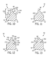
- FIG. 10 is a cross-sectional side view of an embodiment of the blade tip portion 50 of the compressor blade 28 having opposite recesses 200 and 202 configured to reduce stresses in the blade tip portion 50.
- the blade tip portion 50 includes a first concave recess 200, which extends between the first face 52 of the compressor blade 28 and the blade tip 68.
- the blade tip portion 50 includes a second concave recess 202, which extends between the second face 54 of the compressor blade 28 and the blade tip 68.
- the first concave recess 200 and the second concave recess 202 are asymmetrical with respect to the blade tip 68.
- the first concave recess 200 has a radius of curvature 203 and a height 204
- the second concave recess 202 has a radius of curvature 205 and a height 206.
- the height 206 of the second concave recess 202 may be greater than the height 204 of the first concave recess 200 by a factor of approximately 1.05 to 10, 1.1 to 5, or 1.5 to 2.
- the height 204 may be approximately 1 to 5 mm
- the height 206 may be approximately 2 to 10 mm.
- the radii of curvature 203 and 205 and the heights 204 and 206 may be specifically selected to reduce stresses in the blade tip portion 50.
- FIG. 11 is a cross-sectional side view of an embodiment of the blade tip portion 50 of the compressor blade 28 having opposite recesses 220 and 222 configured to reduce stresses in the blade tip 68.
- the illustrated embodiment includes first and second recesses 220 and 222 having different shapes.
- the blade tip portion 50 includes a first recess 220 having a tapered shape, and a second recess 222 having a concave shape.
- the first recess 220 extends between the first face 52 of the compressor blade 28 and the blade tip 68
- the second recess 222 extends between the second face 54 of the compressor blade 28 and the blade tip 68.
- the blade tip portion 50 may having different shapes or configurations of recesses 220 and 222 on the pressure side 56 and the suction side 58 of the compressor blade 28 to reduce stresses in the blade tip portion 50.
- FIG. 12 is a cross-sectional side view of an embodiment of the blade tip portion 50 of the compressor blade 28, illustrating a first recess 230 and a second recess 232 that are asymmetrical relative to the blade tip 68. More particularly, the first recess 230 and the second recess 232 have different shapes.
- the first recess 230 extends between the first face 52 of the compressor blade 28 and the blade tip 68, and has an S-shaped geometry. As discussed above, the S-shaped geometry may include a convex portion 234 and a concave portion 236.
- the radii of curvature 235 and 237 for the convex portion 234 and the concave portion 236 of the first recess 230 may be equal or different from one another.
- the radii of curvature 235 and 237 may be approximately 1 to 50 mm, 2 to 25 mm, or 5 to 10 mm.
- the second recess 232 of the blade tip portion 50 extends between the second face 54 of the compressor blade 28 and the blade tip 68, and has a concave shape.
- the second recess 232 has a radius of curvature 233, which may be equal to or different from the radii of curvature 235 and 237.
- the radii of curvature 233, 235, and 237 may be specifically selected to reduce stresses in the blade tip portion 50.
- FIG. 13 is a cross-sectional side view of an embodiment of the blade tip portion 50 of the compressor blade 28, illustrating a first recess 250 and a second recess 252 that are asymmetrical relative to the blade tip 68. Additionally, the first recess 250 and the second recess 252 have different shapes. Specifically, the first recess 250 extends between the first face 52 of the compressor blade 28 and the blade tip 68, and has a convex shape. The second recess 252 extends between the second face 54 of the compressor blade 28 and the blade tip 68, and has a concave shape.
- the first recess 250 and the second recess 252 have different shapes (i.e., concave and convex)
- the first recess 250 and the second recess 252 may have radii of curvature 251 and 253, which are equal or different from one another.
- the radii of curvature 251 and 253 may be approximately 1 to 50 mm, 2 to 25 mm, or 5 to 10 mm.
- the configuration and radii of curvature 251 and 253 of the recesses 250 and 252 may be specifically selected to reduce stresses in the blade tip portion 50.
Landscapes
- Engineering & Computer Science (AREA)
- Mechanical Engineering (AREA)
- General Engineering & Computer Science (AREA)
- Structures Of Non-Positive Displacement Pumps (AREA)
Abstract
Description
- The subject matter disclosed herein relates to compressors and, more particularly, to a compressor blade tip geometry for reducing tip stresses and increasing tip rub tolerance.
- Gas turbine systems typically include at least one gas turbine engine having a compressor, a combustor, and a turbine. The compressor is configured to use compressor blades to compress and feed air into the combustor for combustion with fuel. For instance, the compressor blades may extend radially outwards from a supporting rotor disk, and the rotation of the compressor blades may force air into the combustor. Unfortunately, compressor blades experience high stresses due to elevated temperatures, fatigue, and elevated pressures. Additionally, the tips of compressor blades can potentially rub against the wall of the compressor, adding additional stress to the tip portions of the compressor blades. The high stresses experienced by compressor blades may cause the tips to suffer from tip liberations, such as cracks or fractures. In certain circumstances, cracks or fractures may cause leakage around the tips of the compressor blades, which subsequently decreases the efficiency of the compressor. As a result, damaged compressor blades may require that the compressor be shut down to repair or replace the damaged compressor blades.
- Certain embodiments commensurate in scope with the originally claimed invention are summarized below. These embodiments are not intended to limit the scope of the claimed invention, but rather these embodiments are intended only to provide a brief summary of possible forms of the invention. Indeed, the invention may encompass a variety of forms that may be similar to or different from the embodiments set forth below.
- In a first embodiment, a system includes a compressor having a plurality of compressor blades coupled to a rotor. Each compressor blade has a first and second face extending to a blade tip portion. The blade tip portion has a blade tip, a first recess between the first face and the blade tip, and a second recess between the second face and the blade tip.
- In a second embodiment, a system includes a compressor blade having a blade tip extending between a leading edge and a trailing edge. The compressor blade also had a first recess extending along a first side of the blade tip between the leading edge and the trailing edge and a second recess extending along a second side of the blade tip between the leading edge and the trailing edge. The first and second recesses of the compressor blade are configured to reduce stress in the compressor blade.
- In a third embodiment, a system includes a compressor blade having a tip, a first recess disposed on a first side of the blade tip, and a second recess disposed on a second side of the blade tip. The first and second recesses of the compressor blade are asymmetrical relative to the blade tip.
- These and other features, aspects, and advantages of the present invention will become better understood when the following detailed description is read with reference to the accompanying drawings in which like characters represent like parts throughout the drawings, wherein:
-
FIG. 1 is a schematic of an embodiment of a gas turbine system including a compressor having a compressor blade configured to reduce stresses in a blade tip portion; -
FIG. 2 is a partial perspective view of an embodiment of a compressor blade, taken within line 2-2 ofFIG. 1 , illustrating a blade tip portion with first and second recesses disposed on opposite sides of the compressor blade to reduce stresses in the blade tip portion; -
FIG. 3 is a top view of an embodiment of the compressor blade ofFIG. 2 , taken along line 3-3; -
FIG. 4 is a top view of an embodiment of the compressor blade ofFIG. 2 , taken along line 3-3; -
FIG. 5 is a cross-sectional side view of an embodiment of the blade tip portion ofFIG. 2 , illustrating opposite first and second concave recesses configured to reduce stresses in the blade tip portion; -
FIG. 6 is a cross-sectional side view of an embodiment of the blade tip portion ofFIG. 2 , illustrating opposite first and second S-shaped recesses configured to reduce stresses in the blade tip portion; -
FIG. 7 is a cross-sectional side view of an embodiment of the blade tip portion ofFIG. 2 , illustrating opposite first and second convex recesses configured to reduce stresses in the blade tip portion; -
FIG. 8 is a cross-sectional side view of an embodiment of the blade tip portion ofFIG. 2 , illustrating opposite first and second tapered recesses configured to reduce stresses in the blade tip portion; -
FIG. 9 is a cross-sectional side view of an embodiment of the blade tip portion ofFIG. 2 , illustrating first and second concave recesses asymmetrically arranged about opposite sides of the blade tip; -
FIG. 10 is a cross-sectional side view of an embodiment of the blade tip portion ofFIG. 2 , illustrating first and second concave recesses asymmetrically arranged about opposite sides of the blade tip; -
FIG. 11 is a cross-sectional side view of an embodiment of the blade tip portion, illustrating a first concave recess and a second tapered recess asymmetrically arranged about opposite sides of the blade tip; -
FIG. 12 is a cross-sectional side view of an embodiment of the blade tip portion, illustrating a first concave recess and a second S-shaped recess asymmetrically arranged about opposite sides of the blade tip; and -
FIG. 13 is a cross-sectional side view of an embodiment of the blade tip portion, illustrating a first concave recess and a second convex recess asymmetrically arranged about opposite sides of the blade tip. - One or more specific embodiments of the present invention will be described below. In an effort to provide a concise description of these embodiments, all features of an actual implementation may not be described in the specification. It should be appreciated that in the development of any such actual implementation, as in any engineering or design project, numerous implementation-specific decisions must be made to achieve the developers' specific goals, such as compliance with system-related and business-related constraints, which may vary from one implementation to another. Moreover, it should be appreciated that such a development effort might be complex and time consuming, but would nevertheless be a routine undertaking of design, fabrication, and manufacture for those of ordinary skill having the benefit of this disclosure.
- When introducing elements of various embodiments of the present invention, the articles "a," "an," "the," and "said" are intended to mean that there are one or more of the elements. The terms "comprising," "including," and "having" are intended to be inclusive and mean that there may be additional elements other than the listed elements.
- As discussed further below, certain embodiments of the present disclosure provide a compressor that includes compressor blades configured for enhanced stress reduction at the blade tips. For instance, in one embodiment, the compressor blade may include a blade tip portion having a blade tip, a first recess between a first face of the blade and the blade tip, and a second recess between a second face of the blade and the blade tip. The first and second recesses may extend along the blade tip between a leading edge and a trailing edge of the compressor blade. This blade tip portion geometry may be referred to as a double sided squealer tip. The first and second recesses may be formed by removing some blade material at the tip of the blade, while maintaining a mean camber line along the tip of the blade. As used herein, the term "camber line" shall be understood to refer to the curve that is halfway between the pressure side and the suction side of the compressor blade. As will be appreciated, the formation of the two recesses may further reduce stresses at the blade tip and potentially increase rub tolerance at the blade tip, allowing for tighter blade clearances within the compressor case.
- The first and second recesses may extend between a leading edge of the compressor blade and a trailing edge of the compressor blade. Furthermore, the first and second recesses may have similar or different configurations. For example, in some embodiments, the first and second recesses may be symmetrical with respect to the blade tip. In other embodiments, the first and second recesses may be asymmetrical with respect to the blade tip. More specifically, in certain embodiments, the respective depths and/or widths of the first and second recesses may be symmetrical or asymmetrical with respect to the blade tip. Furthermore, the respective configurations of the first and second recesses may be symmetrical or asymmetrical with respect to the blade tip. The shapes may include tapered recesses, concave recesses, convex recesses, S-shaped recesses, curved recesses, or any combination thereof. The geometry of the opposite first and second recesses may be specifically selected to reduce stresses in the blade tip, and may be tailored to operational parameters of the compressor, e.g., pressure, temperature, rotational speed, clearance, materials, and so forth.
- Turning now to the drawings,
FIG. 1 illustrates a block diagram of an embodiment of agas turbine system 10 havingcompressor blades 28 with double-sided squealer tips. Thesystem 10 includes acompressor 12,combustors 14 havingfuel nozzles 16, and aturbine 18. The fuel nozzles 16 route a liquid fuel and/or gas fuel, such as natural gas or syngas, into thecombustors 14. Thecombustors 14 ignite and combust a fuel-air mixture, and then pass hot pressurized combustion gases 20 (e.g., exhaust) into theturbine 18.Turbine blades 22 are coupled to ashaft 24, which is also coupled to several other components throughout theturbine system 10, as illustrated. As thecombustion gases 20 pass through theturbine blades 22 in theturbine 18, theturbine 18 is driven into rotation, which causes theshaft 24 to rotate. Eventually, thecombustion gases 20 exit theturbine 18 via anexhaust outlet 26. - In the illustrated embodiment, the
compressor 22 includescompressor blades 28 with double-sided squealer tips to reduce stresses in the blade tips of theblades 28. Theblades 28 within thecompressor 12 are coupled to theshaft 24, and rotate as theshaft 24 is driven to rotate by theturbine 18, as discussed above. As theblades 28 rotate within thecompressor 12, theblades 28 compress air from an air intake intopressurized air 30, which may be routed to thecombustors 14, thefuel nozzles 16, and other portions of thegas turbine system 10. The fuel nozzles 14 may then mix the pressurized air and fuel to produce a suitable fuel-air mixture, which combusts in thecombustors 14 to generate thecombustion gases 20 to drive theturbine 18. Further, theshaft 24 may be coupled to aload 32, which may be powered via rotation of theshaft 24. By way of example, theload 32 may be any suitable device that may generate power via the rotational output of theturbine system 10, such as a power generation plant or an external mechanical load. For instance, theload 32 may include an electrical generator, a propeller of an airplane, and so forth. -
FIG. 2 is a partial perspective view of an embodiment of acompressor blade 28, taken within line 2-2 ofFIG. 1 , illustrating ablade tip portion 50 having opposite recesses configured to reduce stresses in the blade tip of thecompressor blade 28. More specifically, thecompressor blade 28 has afirst face 52 and asecond face 54 that extend to theblade tip portion 50. As will be appreciated, thefirst face 52 may be apressure side 56 of thecompressor blade 28, and thesecond face 54 may be asuction side 58 of thecompressor blade 28. More particularly, as thecompressor blade 28 rotates about theshaft 24 in adirection 60, the air within thecompressor 12 may cause a pressure force to build against thefirst face 52, as indicated byreference numeral 62. Furthermore, as illustrated, thefirst face 52 and thesecond face 54 may be joined together at aleading edge 64 and a trailingedge 66. Additionally, the leadingedge 64 may be the upstream end of thecompressor blade 28, and the trailingedge 66 may be the downstream end of thecompressor blade 28. In certain embodiments, the first face 52 (i.e., the pressure side 56) may have a concave surface, and the second face 54 (i.e., the suction side 58) may have a convex surface. In other embodiments, thefirst face 52 and thesecond face 54 may each have a substantially planar surface. - As shown in the illustrated embodiment, the
blade tip portion 50 includes ablade tip 68, afirst recess 70, and asecond recess 72. Thefirst recess 70 and thesecond recess 72 may be formed by removing material from both sides of theblade tip 68 of thecompressor blade 28. In other words, thefirst recess 70 may be formed by removing material from thepressure side 56 of theblade tip 68, and thesecond recess 72 may be formed by removing material on thesuction side 58 of theblade tip 68. Theblade tip 68 has amiddle portion 74, which may be unmodified to maintain a mean camber line. Moreover, thefirst recess 70 may transition back to thefirst face 52 at anedge 76. Similarly, thesecond recess 72 may transition back to thesecond face 54 at anedge 78. As discussed below, in certain embodiments, thefirst recess 70 and thesecond recess 72 may extend between theleading edge 64 and the trailingedge 66, along theblade tip 68. Further, thefirst recess 70 and thesecond recess 72 may be formed using a variety of machining processes. For example, thefirst recess 70 and thesecond recess 72 may be formed by milling or turning. As discussed in further detail below, thefirst recess 70 and thesecond recess 72 may have a variety of geometries, e.g., shapes and dimensions. In some embodiments, thefirst recess 70 and thesecond recess 72 may have identical or similar geometries, such as shapes and dimensions. For example, the first andsecond recesses recesses second recesses recesses recesses blade tip portion 50. -
FIG. 3 is a top view of an embodiment of thecompressor blade 28 ofFIG. 2 , taken along line 3-3, illustrating theblade tip portion 50 having opposite recesses configured to reduce stresses in theblade tip 68. More specifically, the illustrated embodiment shows theblade tip 68, thefirst recess 70, and thesecond recess 72. As previously mentioned, themiddle portion 74 of theblade tip 68 remains unmodified to maintain amean camber line 100. The illustrated embodiment shows theblade tip 68 having athickness 102 that is uniform. For example, thethickness 102 of theblade tip 68 may be approximately constant (e.g., approximately 1 to 5 mm, 5 to 10 mm, or 10 to 15 mm) between theleading edge 64 and the trailingedge 66 of thecompressor blade 28. Due to theuniform thickness 102 of theblade tip 68, thefirst recess 70 and thesecond recess 72 extend completely or continuously from the leadingedge 64 to the trailingedge 66. Similarly, thefirst recess 70 may have athickness 104 and thesecond recess 72 may have athickness 106. In the illustrated embodiment, thethickness 104 and thethickness 106 are approximately equal as thefirst recess 70 and thesecond recess 72 extend between theleading edge 64 and the trailingedge 66. For example, thethickness 104 and thethickness 106 may be approximately 1 to 5 mm or 5 to 10 mm. -
FIG. 4 is a top view of an embodiment of thecompressor blade 28 illustrating theblade tip portion 50 having opposite recesses configured to reduce stresses in theblade tip 68. More specifically, theblade tip portion 50 includes theblade tip 68 having a varyingthickness 102. For example, thethickness 102 of theblade tip 68 may be approximately 1-2 mm at theleading edge 64, and thethickness 102 may increase linearly (i.e., at a constant rate) to approximately 5 to 10 mm or 10 to 15 mm at the trailingedge 66. However, the dimensions may vary between different implementations of theblade tip portion 50. Furthermore, thethickness 102 may increase linearly or nonlinearly from the leadingedge 64 to the trailingedge 66. For example, thethickness 102 may increase by a factor of approximately 0.1 to 50, 0.1 to 20, or 0.1 to 10 from the leadingedge 64 to the trailingedge 66. Consequently, thefirst recess 70 and thesecond recess 72 may not extend entirely from the leadingedge 64 to the trailingedge 66. In the illustrated embodiment, thefirst recess 70 and thesecond recess 72 extend partially along theblade tip 68. In other words, as thethickness 102 of theblade tip 68 increases, awidth 104 of thefirst recess 70 may decrease, awidth 106 of thesecond recess 72 may decrease, or both thewidths thickness 102 of theblade tip 68 approaches athickness 108 of thecompressor blade 28, thefirst recess 70 and thesecond recess 72 may no longer continue along theblade tip 68. Accordingly, the illustrated recesses 70 and 72 extend to the leadingedge 64, but do not fully extend to the trailingedge 66. However, the double-sided squealer tip provided by therecesses blade tip portion 50 to reduce the possibility of stress cracks, breakage, or general failure of thecompressor blades 28. -
FIGS. 5-13 illustrate various embodiments of theblade tip portion 50 having opposite recesses configured to reduce stresses in theblade tip 68 of thecompressor blade 28. As mentioned above, thefirst recess 70 and thesecond recess 72 may comprise a wide variety of configurations including similar or different curvatures, tapers, and dimensions. Furthermore, thefirst recess 70 and thesecond recess 72 may be symmetrical relative to theblade tip 68, or thefirst recess 70 and thesecond recess 72 may be asymmetrical relative to theblade tip 68, as discussed in further detail below. -
FIG. 5 is a cross-sectional side view of an embodiment of theblade tip portion 50 of thecompressor blade 28 havingrecesses blade tip 68. As shown, theblade tip portion 50 includes theblade tip 68, a firstconcave recess 110, and a secondconcave recess 112. As mentioned above, theblade tip 68 has athickness 102. Further, theblade tip 68 may have aheight 114. For example, theheight 114 of theblade tip 68 may be approximately 1 to 10 mm, 2 to 8 mm, or 3 to 5 mm. As shown, the firstconcave recess 110 extends between thefirst face 52 and theblade tip 68. Similarly, the secondconcave recess 112 extends between thesecond face 54 and theblade tip 68. As will be appreciated, a radius ofcurvature 111 for the firstconcave recess 110 and a radius ofcurvature 113 for the secondconcave recess 112 may vary. For example, the radii ofcurvature concave recess 110 and the secondconcave recess 112 may be approximately 1 to 50 mm, 2 to 25 mm, or 5 to 10 mm. In certain embodiments, the radii ofcurvature concave recess 110 and the secondconcave recess 112 may be equal. In other embodiments, the firstconcave recess 110 and the secondconcave recess 112 may have different radii ofcurvature concave recess 110 may be modified, as indicated by the dottedline 116, to have a radius ofcurvature 117, which is substantially different from the radius ofcurvature 113 of the secondconcave recess 112. In either case, theradii blade tip portion 50. -
FIG. 6 is a cross-sectional side view of an embodiment of theblade tip portion 50 of thecompressor blade 28 havingopposite recesses blade tip portion 50. Theblade tip portion 50 includes theblade tip 68, a first S-shapedrecess 130, and a second S-shapedrecess 132. As previously mentioned, theblade tip 68 has athickness 102 and aheight 114. The first S-shapedrecess 130 extends between thefirst face 52 and theblade tip 68. Similarly, the second S-shapedrecess 132 extends between thesecond face 54 and theblade tip 68. As illustrated, the first S-shapedrecess 130 has aconvex portion 134 and aconcave portion 136. Similarly, the second S-shapedrecess 132 has aconvex portion 138 and a concave 140. In one embodiment, theconvex portions concave portions curvature convex portions concave portions curvature convex portion 134 of the first S-shapedrecess 130 and theconvex portion 138 of the second S-shapedrecess 132 may both have a first radii ofcurvature concave portion 136 of the first S-shapedrecess 130 and theconcave portion 140 of the second S-shapedrecess 132 may both have a second radii ofcurvature curvature curvature blade tip portion 50. -
FIG. 7 is a cross-sectional side view of an embodiment of theblade tip portion 50 of thecompressor blade 28 illustrating theblade tip 68, a firstconvex recess 150, and a secondconvex recess 152. As previously discussed, theblade tip portion 50 has therecesses blade tip 68. As shown in the illustrated embodiment, the firstconvex recess 150 extends between thefirst face 52 of thecompressor blade 28 and theblade tip 68. Further, the secondconvex recess 152 extends between thesecond face 54 of thecompressor blade 28 and theblade tip 68. In certain embodiments, the firstconvex recess 150 and the secondconvex recess 152 may have equal or different radii ofcurvature curvature convex recess 150 and the secondconvex recess 152 may be approximately 1 to 50 mm, 2 to 25 mm, or 5 to 10 mm. Again, the radii ofcurvature blade tip portion 50. -
FIG. 8 is a cross-sectional side view of an embodiment of theblade tip portion 50 of thecompressor blade 28 havingopposite recesses blade tip portion 50. Specifically, the illustrated embodiment includes a firsttapered recess 170 and a secondtapered recess 172 configured to reduce stresses in theblade tip 68. As shown, the firsttapered recess 170 has a straight orflat surface 174 extending between thefirst face 52 of thecompressor blade 28 and theblade tip 68. Similarly, the secondtapered recess 172 has a straight orflat surface 176 extending from thesecond face 54 of thecompressor blade 28 and theblade tip 68. While the firsttapered recess 170 and thesecond recess 172 are symmetrical with respect to theblade tip 68 in the illustrated embodiment, the firsttapered recess 170 and the secondtapered recess 172 may be asymmetrical with respect to theblade tip 68 in other embodiments. As illustrated, thesurface 174 of the firsttapered recess 170 has afirst angle 175 relative to thefirst face 52, and thesurface 176 of the secondtapered recess 172 has asecond angle 177 relative to thesecond face 54. In certain embodiments, theangles angle 175 may be greater than theangle 177, or theangle 177 may be greater than theangle 175. Theangles angles blade tip portion 50. -
FIG. 9 is a cross-sectional side view of an embodiment of theblade tip portion 50 of thecompressor blade 28 havingopposite recesses blade tip portion 50. The illustrated embodiment includes a firstconcave recess 180 and a secondconcave recess 182 configured to reduce stresses in theblade tip 68. As shown, the firstconcave recess 180 extends from thefirst face 52 of thecompressor blade 28 to theblade tip 68. Similarly, the secondconcave recess 182 extends from thesecond face 54 of the compressor blade to theblade tip 68. Further, the firstconcave recess 180 and the secondconcave recess 182 are asymmetrical with respect to theblade tip 68. Thus, the first and secondconcave recesses curvature blade tip 68 is offset adistance 184 relative to amean camber line 186 extending between the leading edge and the trailing edge of thecompressor blade 28. For example, thedistance 184 may be approximately 1 to 95 percent, 5 to 75 percent, 10 to 50 percent, or 20 to 40 percent of adistance 185 from thecamber line 186 toward thefirst face 52 or adistance 187 from thecamber line 186 toward thesecond face 54. For example, thedistance 184 may be approximately 1 to 10 mm, 1 to 5 mm, or 2 to 3 mm. As shown, theblade tip 68 is offset thedistance 184 towards thepressure side 56 of the compressor blade 28 (i.e., a fraction of the distance 185). In other embodiments, theblade tip 68 may be offset from themean camber line 186 towards thesuction side 58 of the compressor blade 28 (i.e., a fraction of the distance 187). The radii ofcurvature distance 184 may be specifically selected to reduce stresses in theblade tip portion 50. -
FIG. 10 is a cross-sectional side view of an embodiment of theblade tip portion 50 of thecompressor blade 28 havingopposite recesses blade tip portion 50. As shown, theblade tip portion 50 includes a firstconcave recess 200, which extends between thefirst face 52 of thecompressor blade 28 and theblade tip 68. Additionally, theblade tip portion 50 includes a secondconcave recess 202, which extends between thesecond face 54 of thecompressor blade 28 and theblade tip 68. Furthermore, the firstconcave recess 200 and the secondconcave recess 202 are asymmetrical with respect to theblade tip 68. In particular, the firstconcave recess 200 has a radius ofcurvature 203 and aheight 204, while the secondconcave recess 202 has a radius ofcurvature 205 and aheight 206. For example, theheight 206 of the secondconcave recess 202 may be greater than theheight 204 of the firstconcave recess 200 by a factor of approximately 1.05 to 10, 1.1 to 5, or 1.5 to 2. By further example, theheight 204 may be approximately 1 to 5 mm, while theheight 206 may be approximately 2 to 10 mm. Again, the radii ofcurvature heights blade tip portion 50. -
FIG. 11 is a cross-sectional side view of an embodiment of theblade tip portion 50 of thecompressor blade 28 havingopposite recesses blade tip 68. Specifically, the illustrated embodiment includes first andsecond recesses blade tip portion 50 includes afirst recess 220 having a tapered shape, and asecond recess 222 having a concave shape. Thefirst recess 220 extends between thefirst face 52 of thecompressor blade 28 and theblade tip 68, and thesecond recess 222 extends between thesecond face 54 of thecompressor blade 28 and theblade tip 68. As previously discussed, theblade tip portion 50 may having different shapes or configurations ofrecesses pressure side 56 and thesuction side 58 of thecompressor blade 28 to reduce stresses in theblade tip portion 50. -
FIG. 12 is a cross-sectional side view of an embodiment of theblade tip portion 50 of thecompressor blade 28, illustrating afirst recess 230 and asecond recess 232 that are asymmetrical relative to theblade tip 68. More particularly, thefirst recess 230 and thesecond recess 232 have different shapes. Thefirst recess 230 extends between thefirst face 52 of thecompressor blade 28 and theblade tip 68, and has an S-shaped geometry. As discussed above, the S-shaped geometry may include aconvex portion 234 and aconcave portion 236. In certain embodiments, the radii ofcurvature convex portion 234 and theconcave portion 236 of thefirst recess 230 may be equal or different from one another. For example, the radii ofcurvature second recess 232 of theblade tip portion 50 extends between thesecond face 54 of thecompressor blade 28 and theblade tip 68, and has a concave shape. Thesecond recess 232 has a radius ofcurvature 233, which may be equal to or different from the radii ofcurvature curvature blade tip portion 50. -
FIG. 13 is a cross-sectional side view of an embodiment of theblade tip portion 50 of thecompressor blade 28, illustrating afirst recess 250 and asecond recess 252 that are asymmetrical relative to theblade tip 68. Additionally, thefirst recess 250 and thesecond recess 252 have different shapes. Specifically, thefirst recess 250 extends between thefirst face 52 of thecompressor blade 28 and theblade tip 68, and has a convex shape. Thesecond recess 252 extends between thesecond face 54 of thecompressor blade 28 and theblade tip 68, and has a concave shape. Although thefirst recess 250 and thesecond recess 252 have different shapes (i.e., concave and convex), thefirst recess 250 and thesecond recess 252 may have radii ofcurvature 251 and 253, which are equal or different from one another. For example, the radii ofcurvature 251 and 253 may be approximately 1 to 50 mm, 2 to 25 mm, or 5 to 10 mm. Again, the configuration and radii ofcurvature 251 and 253 of therecesses blade tip portion 50. - This written description uses examples to disclose the invention, including the best mode, and also to enable any person skilled in the art to practice the invention, including making and using any devices or systems and performing any incorporated methods. The patentable scope of the invention is defined by the claims, and may include other examples that occur to those skilled in the art. Such other examples are intended to be within the scope of the claims if they have structural elements that do not differ from the literal language of the claims, or if they include equivalent structural elements with insubstantial differences from the literal language of the claims.
Claims (15)
- A system, comprising:a compressor, comprising:a plurality of compressor blades (28) coupled to a rotor (24); wherein each compressor blade comprises first and second external faces (50,52) extending to a blade tip portion (50), wherein the blade tip portion comprises a blade tip (68), a first external recess (70) between the first face (52) and the blade tip (68), and a second external recess (72) between the second face (54) and the blade tip (68).
- The system of claim 1, wherein the first and second external recesses (70,72) of each compressor blade are configured to reduce stress in the blade tip portion.
- The system of claim 1 or claim 2, wherein the first and second external recesses (70,72) of each compressor blade extend along the blade tip (68) between a leading edge (64) and a trailing edge (66).
- The system of any preceding claim, wherein the blade tip (68) of each compressor blade is centered along a camber line (100) of the compressor blade.
- The system of any preceding claim, wherein the first and second external recesses (70,72) of each compressor blade are asymmetrical relative to the blade tip (68).
- The system of claim 5, wherein the first and second external recesses (70,72) of each compressor blade comprise respective first and second curvatures that are asymmetrical relative to the blade tip, or first and second depths that are asymmetrical relative to the blade tip, or first and second widths that are asymmetrical relative to the blade tip.
- The system of any preceding claim, wherein at least one of the first or second external recesses (70,72) of each compressor blade comprises at least one of a concave recess, a convex recess, or a tapered recess.
- A system, comprising:a compressor blade (28) comprising a blade tip (68) extending between a leading edge (64) and a trailing edge (66), a first external recess (70) extending along a first side (52) of the blade tip between the leading edge and the trailing edge, and a second external recess (72) extending along a second side (54) of the blade tip between the leading edge and the trailing edge, wherein the first and second external recesses are configured to reduce stress in the compressor blade.
- The system of claim 8, wherein at least one of the first or second external recesses (70,72) comprises at least one of a concave external recess, a convex external recess, or a tapered external recess.
- The system of claim 8, wherein at least one of the first or second external recesses (70,72) comprises an S-shaped external recess.
- The system of any one of claims 8 to 10, wherein the blade tip (68) is centered along a camber line (100) extending between the leading edge (64) and the trailing edge (66) of the compressor blade.
- The system of any one of claims 8 to 11, wherein the first and second external recesses (70,72) are asymmetrical relative to the blade tip.
- A system, comprising:a compressor blade comprising a blade tip (68), a first external recess (70) disposed on a first side (52) of the blade tip, and a second external recess (72) disposed on a second side (54) of the blade tip, wherein the first and second external recesses are asymmetrical relative to the blade tip.
- The system of claim 13, wherein the first and second external recesses (70,72) comprise respective first and second curvatures that are asymmetrical relative to the blade tip.
- The system of claim 13 or claim 14, wherein the blade tip (68), the first external recess (70), and the second external recess (72) extend between a leading edge (64) and a trailing edge (66), and the blade tip is offset relative to a camber line (100) extending between the leading edge and the trailing edge.
Applications Claiming Priority (1)
| Application Number | Priority Date | Filing Date | Title |
|---|---|---|---|
| US13/091,059 US8790088B2 (en) | 2011-04-20 | 2011-04-20 | Compressor having blade tip features |
Publications (2)
| Publication Number | Publication Date |
|---|---|
| EP2514922A2 true EP2514922A2 (en) | 2012-10-24 |
| EP2514922A3 EP2514922A3 (en) | 2014-08-13 |
Family
ID=46022077
Family Applications (1)
| Application Number | Title | Priority Date | Filing Date |
|---|---|---|---|
| EP12164032.0A Withdrawn EP2514922A3 (en) | 2011-04-20 | 2012-04-13 | Compressor with blade tip geometry for reducing tip stresses |
Country Status (3)
| Country | Link |
|---|---|
| US (1) | US8790088B2 (en) |
| EP (1) | EP2514922A3 (en) |
| CN (1) | CN102758792A (en) |
Cited By (8)
| Publication number | Priority date | Publication date | Assignee | Title |
|---|---|---|---|---|
| WO2014137443A2 (en) | 2012-12-28 | 2014-09-12 | United Technologies Corporation | Gas turbine engine turbine blade tip cooling |
| EP2952685A1 (en) * | 2014-06-04 | 2015-12-09 | United Technologies Corporation | Airfoil, corresponding gas turbine engine and method of reducing frictional heating |
| EP2935790B1 (en) * | 2012-12-19 | 2019-05-01 | Rolls-Royce PLC | Composite aerofoil structure with a cutting edge tip portion |
| EP3477059A1 (en) * | 2017-10-26 | 2019-05-01 | Siemens Aktiengesellschaft | Compressor aerofoil |
| EP3561226A1 (en) | 2018-04-24 | 2019-10-30 | Siemens Aktiengesellschaft | Compressor aerofoil |
| WO2021110192A1 (en) * | 2019-12-04 | 2021-06-10 | MTU Aero Engines AG | Guide vane arrangement for a turbomachine |
| WO2021191559A1 (en) * | 2020-03-26 | 2021-09-30 | Safran Aircraft Engines | Turbomachine rotary-fan blade, fan and turbomachine provided therewith |
| WO2023242949A1 (en) * | 2022-06-14 | 2023-12-21 | 三菱重工業株式会社 | Compressor rotor blade and compressor |
Families Citing this family (17)
| Publication number | Priority date | Publication date | Assignee | Title |
|---|---|---|---|---|
| GB201017797D0 (en) * | 2010-10-21 | 2010-12-01 | Rolls Royce Plc | An aerofoil structure |
| EP2530330B1 (en) * | 2011-06-01 | 2016-05-25 | MTU Aero Engines AG | Rotor blade for the compressor of a turbo engine, compressor and turbo machine |
| US20130149163A1 (en) * | 2011-12-13 | 2013-06-13 | United Technologies Corporation | Method for Reducing Stress on Blade Tips |
| IN2014DN09484A (en) * | 2012-04-23 | 2015-07-17 | Borgwarner Inc | |
| KR101925892B1 (en) | 2012-04-23 | 2018-12-06 | 보르그워너 인코퍼레이티드 | Turbocharger shroud with cross-wise grooves and turbocharger incorporating the same |
| US9896937B2 (en) | 2012-04-23 | 2018-02-20 | Borgwarner Inc. | Turbine hub with surface discontinuity and turbocharger incorporating the same |
| EP2696031B1 (en) * | 2012-08-09 | 2015-10-14 | MTU Aero Engines AG | Blade for a flow machine engine and corresponding flow machine engine. |
| JP6184173B2 (en) * | 2013-05-29 | 2017-08-23 | 三菱日立パワーシステムズ株式会社 | gas turbine |
| FR3010463B1 (en) * | 2013-09-11 | 2015-08-21 | IFP Energies Nouvelles | POLYPHASE PUMP IMPLUSTER WITH MEANS FOR AMPLIFYING AND DISTRIBUTING GAME FLOWS. |
| CN103500287B (en) * | 2013-10-16 | 2016-04-20 | 东北大学 | The defining method of rotary blade-box rub-impact force |
| US20160237831A1 (en) * | 2015-02-12 | 2016-08-18 | United Technologies Corporation | Abrasive blade tip with improved wear at high interaction rate |
| US10385865B2 (en) | 2016-03-07 | 2019-08-20 | General Electric Company | Airfoil tip geometry to reduce blade wear in gas turbine engines |
| US10633983B2 (en) | 2016-03-07 | 2020-04-28 | General Electric Company | Airfoil tip geometry to reduce blade wear in gas turbine engines |
| EP3421724A1 (en) * | 2017-06-26 | 2019-01-02 | Siemens Aktiengesellschaft | Compressor aerofoil |
| US10584713B2 (en) | 2018-01-05 | 2020-03-10 | Spectrum Brands, Inc. | Impeller assembly for use in an aquarium filter pump and methods |
| CN111219362A (en) * | 2018-11-27 | 2020-06-02 | 中国航发商用航空发动机有限责任公司 | Axial compressor blade, axial compressor and gas turbine |
| DE102021130682A1 (en) * | 2021-11-23 | 2023-05-25 | MTU Aero Engines AG | Airfoil for a turbomachine |
Family Cites Families (17)
| Publication number | Priority date | Publication date | Assignee | Title |
|---|---|---|---|---|
| US899319A (en) * | 1906-10-08 | 1908-09-22 | Charles Algernon Parsons | Turbine. |
| FR2623569A1 (en) * | 1987-11-19 | 1989-05-26 | Snecma | VANE OF COMPRESSOR WITH DISSYMMETRIC LETTLE LETCHES |
| GB9112043D0 (en) * | 1991-06-05 | 1991-07-24 | Sec Dep For The Defence | A titanium compressor blade having a wear resistant portion |
| US5476363A (en) * | 1993-10-15 | 1995-12-19 | Charles E. Sohl | Method and apparatus for reducing stress on the tips of turbine or compressor blades |
| JP3453268B2 (en) * | 1997-03-04 | 2003-10-06 | 三菱重工業株式会社 | Gas turbine blades |
| JP2000130102A (en) * | 1998-10-29 | 2000-05-09 | Ishikawajima Harima Heavy Ind Co Ltd | Rotary machine blade tip structure |
| US6206642B1 (en) * | 1998-12-17 | 2001-03-27 | United Technologies Corporation | Compressor blade for a gas turbine engine |
| US6086328A (en) * | 1998-12-21 | 2000-07-11 | General Electric Company | Tapered tip turbine blade |
| JP2001055902A (en) * | 1999-08-18 | 2001-02-27 | Toshiba Corp | Turbine rotor blade |
| GB0216952D0 (en) * | 2002-07-20 | 2002-08-28 | Rolls Royce Plc | Gas turbine engine casing and rotor blade arrangement |
| US6976826B2 (en) * | 2003-05-29 | 2005-12-20 | Pratt & Whitney Canada Corp. | Turbine blade dimple |
| EP1624192A1 (en) * | 2004-08-06 | 2006-02-08 | Siemens Aktiengesellschaft | Impeller blade for axial compressor |
| FR2891594A1 (en) * | 2005-09-30 | 2007-04-06 | Snecma Sa | AUBE COMPRESSOR WITH CHANFREINE TOP |
| US8172541B2 (en) * | 2009-02-27 | 2012-05-08 | General Electric Company | Internally-damped airfoil and method therefor |
| US8657570B2 (en) * | 2009-06-30 | 2014-02-25 | General Electric Company | Rotor blade with reduced rub loading |
| US20110070072A1 (en) * | 2009-09-23 | 2011-03-24 | General Electric Company | Rotary machine tip clearance control mechanism |
| EP2309097A1 (en) * | 2009-09-30 | 2011-04-13 | Siemens Aktiengesellschaft | Airfoil and corresponding guide vane, blade, gas turbine and turbomachine |
-
2011
- 2011-04-20 US US13/091,059 patent/US8790088B2/en active Active
-
2012
- 2012-04-13 EP EP12164032.0A patent/EP2514922A3/en not_active Withdrawn
- 2012-04-20 CN CN2012101296066A patent/CN102758792A/en active Pending
Non-Patent Citations (1)
| Title |
|---|
| None |
Cited By (16)
| Publication number | Priority date | Publication date | Assignee | Title |
|---|---|---|---|---|
| US10669866B2 (en) | 2012-12-19 | 2020-06-02 | Rolls-Royce Plc | Composite aerofoil structure with a cutting edge tip portion |
| EP2935790B1 (en) * | 2012-12-19 | 2019-05-01 | Rolls-Royce PLC | Composite aerofoil structure with a cutting edge tip portion |
| EP2938831A4 (en) * | 2012-12-28 | 2016-03-02 | United Technologies Corp | Gas turbine engine turbine blade tip cooling |
| WO2014137443A2 (en) | 2012-12-28 | 2014-09-12 | United Technologies Corporation | Gas turbine engine turbine blade tip cooling |
| EP2952685A1 (en) * | 2014-06-04 | 2015-12-09 | United Technologies Corporation | Airfoil, corresponding gas turbine engine and method of reducing frictional heating |
| US10876415B2 (en) | 2014-06-04 | 2020-12-29 | Raytheon Technologies Corporation | Fan blade tip as a cutting tool |
| EP3477059A1 (en) * | 2017-10-26 | 2019-05-01 | Siemens Aktiengesellschaft | Compressor aerofoil |
| WO2019081471A1 (en) * | 2017-10-26 | 2019-05-02 | Siemens Aktiengesellschaft | Compressor aerofoil |
| US11274558B2 (en) * | 2017-10-26 | 2022-03-15 | Siemens Energy Global GmbH & Co. KG | Compressor aerofoil |
| WO2019206747A1 (en) | 2018-04-24 | 2019-10-31 | Siemens Aktiengesellschaft | Compressor aerofoil |
| EP3561226A1 (en) | 2018-04-24 | 2019-10-30 | Siemens Aktiengesellschaft | Compressor aerofoil |
| WO2021110192A1 (en) * | 2019-12-04 | 2021-06-10 | MTU Aero Engines AG | Guide vane arrangement for a turbomachine |
| WO2021191559A1 (en) * | 2020-03-26 | 2021-09-30 | Safran Aircraft Engines | Turbomachine rotary-fan blade, fan and turbomachine provided therewith |
| FR3108662A1 (en) * | 2020-03-26 | 2021-10-01 | Safran Aircraft Engines | Turbomachine rotary fan blade, fan and turbomachine fitted therewith |
| US11920494B2 (en) | 2020-03-26 | 2024-03-05 | Safran Aircraft Engines | Turbomachine rotary-fan blade, fan and turbomachine provided therewith |
| WO2023242949A1 (en) * | 2022-06-14 | 2023-12-21 | 三菱重工業株式会社 | Compressor rotor blade and compressor |
Also Published As
| Publication number | Publication date |
|---|---|
| EP2514922A3 (en) | 2014-08-13 |
| CN102758792A (en) | 2012-10-31 |
| US8790088B2 (en) | 2014-07-29 |
| US20120269638A1 (en) | 2012-10-25 |
Similar Documents
| Publication | Publication Date | Title |
|---|---|---|
| US8790088B2 (en) | Compressor having blade tip features | |
| US10253638B2 (en) | Turbomachine blade tip shroud | |
| JP7034587B2 (en) | Turbine rotor blade with shroud | |
| US10190423B2 (en) | Shrouded blade for a gas turbine engine | |
| EP3187689B1 (en) | Shrouded turbine rotor blades | |
| US8807928B2 (en) | Tip shroud assembly with contoured seal rail fillet | |
| US9353629B2 (en) | Turbine blade apparatus | |
| EP2586979B1 (en) | Turbomachine blade with tip flare | |
| EP2650476A2 (en) | Turbomachine blade tip shroud with parallel casing configuration | |
| US9297259B2 (en) | Compressor blade | |
| US9140132B2 (en) | Turbine blade support | |
| US10138736B2 (en) | Turbomachine blade tip shroud | |
| EP2679773B1 (en) | System having blade segment with curved mounting geometry | |
| US11299992B2 (en) | Rotor blade damping structures |
Legal Events
| Date | Code | Title | Description |
|---|---|---|---|
| PUAI | Public reference made under article 153(3) epc to a published international application that has entered the european phase |
Free format text: ORIGINAL CODE: 0009012 |
|
| AK | Designated contracting states |
Kind code of ref document: A2 Designated state(s): AL AT BE BG CH CY CZ DE DK EE ES FI FR GB GR HR HU IE IS IT LI LT LU LV MC MK MT NL NO PL PT RO RS SE SI SK SM TR |
|
| AX | Request for extension of the european patent |
Extension state: BA ME |
|
| PUAL | Search report despatched |
Free format text: ORIGINAL CODE: 0009013 |
|
| AK | Designated contracting states |
Kind code of ref document: A3 Designated state(s): AL AT BE BG CH CY CZ DE DK EE ES FI FR GB GR HR HU IE IS IT LI LT LU LV MC MK MT NL NO PL PT RO RS SE SI SK SM TR |
|
| AX | Request for extension of the european patent |
Extension state: BA ME |
|
| RIC1 | Information provided on ipc code assigned before grant |
Ipc: F04D 29/38 20060101ALI20140710BHEP Ipc: F01D 5/20 20060101AFI20140710BHEP |
|
| STAA | Information on the status of an ep patent application or granted ep patent |
Free format text: STATUS: THE APPLICATION IS DEEMED TO BE WITHDRAWN |
|
| 18D | Application deemed to be withdrawn |
Effective date: 20141101 |