EP2514879A2 - Position control apparatus and method for working machine of construction machinery - Google Patents
Position control apparatus and method for working machine of construction machinery Download PDFInfo
- Publication number
- EP2514879A2 EP2514879A2 EP10837780A EP10837780A EP2514879A2 EP 2514879 A2 EP2514879 A2 EP 2514879A2 EP 10837780 A EP10837780 A EP 10837780A EP 10837780 A EP10837780 A EP 10837780A EP 2514879 A2 EP2514879 A2 EP 2514879A2
- Authority
- EP
- European Patent Office
- Prior art keywords
- boom
- bucket
- signal
- kick
- driving
- Prior art date
- Legal status (The legal status is an assumption and is not a legal conclusion. Google has not performed a legal analysis and makes no representation as to the accuracy of the status listed.)
- Granted
Links
- 238000010276 construction Methods 0.000 title claims abstract description 34
- 238000000034 method Methods 0.000 title claims description 14
- XDDAORKBJWWYJS-UHFFFAOYSA-N glyphosate Chemical compound OC(=O)CNCP(O)(O)=O XDDAORKBJWWYJS-UHFFFAOYSA-N 0.000 claims abstract description 64
- 230000036544 posture Effects 0.000 claims description 39
- 230000005540 biological transmission Effects 0.000 claims description 16
- 239000004576 sand Substances 0.000 description 13
- 239000012530 fluid Substances 0.000 description 6
- 238000004519 manufacturing process Methods 0.000 description 5
- 238000006073 displacement reaction Methods 0.000 description 4
- 238000010586 diagram Methods 0.000 description 2
- 238000009412 basement excavation Methods 0.000 description 1
- 230000000694 effects Effects 0.000 description 1
- 230000007935 neutral effect Effects 0.000 description 1
Images


Classifications
-
- E—FIXED CONSTRUCTIONS
- E02—HYDRAULIC ENGINEERING; FOUNDATIONS; SOIL SHIFTING
- E02F—DREDGING; SOIL-SHIFTING
- E02F9/00—Component parts of dredgers or soil-shifting machines, not restricted to one of the kinds covered by groups E02F3/00 - E02F7/00
- E02F9/20—Drives; Control devices
-
- E—FIXED CONSTRUCTIONS
- E02—HYDRAULIC ENGINEERING; FOUNDATIONS; SOIL SHIFTING
- E02F—DREDGING; SOIL-SHIFTING
- E02F9/00—Component parts of dredgers or soil-shifting machines, not restricted to one of the kinds covered by groups E02F3/00 - E02F7/00
- E02F9/20—Drives; Control devices
- E02F9/2004—Control mechanisms, e.g. control levers
-
- E—FIXED CONSTRUCTIONS
- E02—HYDRAULIC ENGINEERING; FOUNDATIONS; SOIL SHIFTING
- E02F—DREDGING; SOIL-SHIFTING
- E02F3/00—Dredgers; Soil-shifting machines
- E02F3/04—Dredgers; Soil-shifting machines mechanically-driven
- E02F3/28—Dredgers; Soil-shifting machines mechanically-driven with digging tools mounted on a dipper- or bucket-arm, i.e. there is either one arm or a pair of arms, e.g. dippers, buckets
- E02F3/36—Component parts
- E02F3/42—Drives for dippers, buckets, dipper-arms or bucket-arms
- E02F3/43—Control of dipper or bucket position; Control of sequence of drive operations
- E02F3/431—Control of dipper or bucket position; Control of sequence of drive operations for bucket-arms, front-end loaders, dumpers or the like
- E02F3/434—Control of dipper or bucket position; Control of sequence of drive operations for bucket-arms, front-end loaders, dumpers or the like providing automatic sequences of movements, e.g. automatic dumping or loading, automatic return-to-dig
-
- E—FIXED CONSTRUCTIONS
- E02—HYDRAULIC ENGINEERING; FOUNDATIONS; SOIL SHIFTING
- E02F—DREDGING; SOIL-SHIFTING
- E02F9/00—Component parts of dredgers or soil-shifting machines, not restricted to one of the kinds covered by groups E02F3/00 - E02F7/00
-
- E—FIXED CONSTRUCTIONS
- E02—HYDRAULIC ENGINEERING; FOUNDATIONS; SOIL SHIFTING
- E02F—DREDGING; SOIL-SHIFTING
- E02F9/00—Component parts of dredgers or soil-shifting machines, not restricted to one of the kinds covered by groups E02F3/00 - E02F7/00
- E02F9/14—Booms only for booms with cable suspension arrangements; Cable suspensions
Definitions
- the present invention relates to a construction machine such as a wheel loader, and more particularly, to a position control apparatus and a position control method for a working tool of a construction machine for controlling a position of a working tool such as a boom or a bucket.
- a construction machine such as a wheel loader is widely used in an operation of conveying and loading earth and sand.
- the wheel loader raises a boom at a position close to a conveying means such as a truck and dumps a bucket containing earth and sand to load the earth and sand on the conveying means. Then, after the bucket is crowded to a horizontal position, a boom is lowered to fill earth and sand in the bucket. Such an operation is repeated a plurality of times until earth and sand is filled in the conveying means.
- a wheel loader operator needs to repeatedly perform an operation of raising and lowering the bucket from and to the conveying means.
- the above-mentioned position control system needs to manipulate the bucket lever first so that the bucket reaches a specific position, and then manipulate the boom lever to move the boom to a specific position. That is, since the position control system needs to individually manipulate the bucket lever and the boom lever, manipulation efficiency is lowered. In addition, since the boom needs to be moved to a specific position only after the bucket is moved to the specific position thereof, an operation cannot be promptly performed.
- the present invention has been made in an effort to provide a position control apparatus and a position control method for a working tool of a construction machine which can reduce manufacturing costs, enhance manipulation efficiency, and improve operation speed.
- the present invention provides a position control apparatus for a working tool of a construction machine, including: a boom driving unit 21 for driving a boom 20; a bucket driving unit 31 for driving a bucket 30; a working tool manipulating part 40 for generating a manipulation signal for driving the boom driving unit 21 and the bucket driving unit 31; a kick-down switch 50 for generating a kick-down signal for lowering a gear stage; and a controller 80 for, if the kick-down signal is generated by the kick-down switch 50 and the manipulation signal is generated by the working tool manipulating part 40, outputting a control signal to the boom driving unit 21 and the bucket driving unit 31 to move the boom 20 and the bucket 30 to a preset position.
- the manipulation signal of the working tool manipulating part 40 for moving the boom 20 and the bucket 30 to the preset position may be a boom-down signal.
- the controller 80 may output the kick-down signal to a transmission control unit 51 to lower a gear stage.
- the position control apparatus for a working tool may further include: a boom posture detecting sensor 60 for detecting a posture of the boom 20; and a bucket posture detecting sensor 70 for detecting a posture of the bucket 30. If the kick-down signal and the boom-down signal are input, the controller 80 may drive the boom driving unit 21 and the bucket driving unit 31 until the signals output by the boom posture detecting sensor 60 and the bucket posture detecting sensor 70, respectively are the same as signals for the postures of the boom 20 and the bucket 30 corresponding to the preset position.
- the working tool manipulating part 40 may include: a boom manipulating part 41 for generating a manipulation signal for driving the boom 20; and a bucket manipulating part 42 for generating a manipulation signal for driving the bucket 30.
- the kick-down switch 50 may be installed in the boom manipulating part 41, and the preset position may be a position of the bucket 30 where a bottom surface of the bucket 30 is parallel to the ground surface and a position of the boom 20 where the bottom surface of the bucket 30 is close to the ground surface.
- the present invention provides a position control method for a working tool of a construction machine for controlling positions of a boom 20 and a bucket 30, the method comprising: (a) if a kick-down signal is input, determining whether or not a boom-down signal is input; (b) if the determination result of (a) step shows that the boom-down signal is not input, outputting the kick-down signal to a transmission control unit; and (c) if the determination result of (a) step shows that the boom-down signal is input, moving the boom 20 and the bucket 30 to a preset position without outputting the kick-down signal to the transmission control unit.
- a boom and a bucket can be automatically moved to a preset position by a kick-down switch and a manipulation signal of a working tool manipulating part, an existing system using an electromagnet can be omitted and a separate switch is not required, making it possible to minimize manufacturing costs of a construction machine.
- a boom-down signal is used as a signal for automatically moving the working tool to a preset position together with a kick-down signal, an operator can easily recognize and use an automatic movement signal, and accordingly, manipulation efficiency of the construction machine can be enhanced.
- a kick-down switch is installed in a boom manipulating part, the kick-down switch and the boom manipulating part can be manipulated by one hand, and accordingly, manipulation efficiency of the construction machine can be further enhanced.
- the present invention is adapted to control a position of a working tool 20 and 30, and the working tool 20 and 30 includes a boom 20 and a bucket 30.
- the boom 20 is installed in a body of the construction machine to be rotated upward and downward
- the bucket 30 is installed in the boom 20 to be rotated upward and downward.
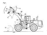
- the construction machine moves to a location close to a conveying means in a posture of the boom 20 and the bucket 30 as illustrated by A of FIG. 1 .
- the bucket 30 is dumped to state C via state B to load earth and sand contained in the bucket 30 on the conveying means.
- the state D is a state where the bottom surface of the bucket 30 is parallel to the ground surface and the bottom surface of the bucket 30 is very close to the ground surface.
- the present invention relates to a position control apparatus and a position control method for automatically changing a working tool in the state where the bucket 30 is dumped and the boom 20 is raised as in C to a state (preset position) where the bucket 30 is horizontal and the boom 20 is lowered as in D promptly and easily.
- the position control apparatus for a working tool of a construction machine includes a boom driving unit 21 for driving the boom 20, a bucket driving unit 31 for driving the bucket 30, a working tool manipulating part 40 for generating a manipulation signal for driving the boom driving unit 21 and the bucket driving unit 31, a kick-down switch 50, a controller 80, a boom posture detecting sensor 60 and a bucket posture detecting sensor 70.
- the boom driving unit 21 is adapted to drive the boom 20, and includes a boom control valve 22 for controlling a flow direction of a working fluid discharged from the pump 10, and a boom cylinder 23 to which the working fluid whose a flow direction has been controlled by the boom control valve 22 is supplied such that the boom cylinder 23 is driven.
- the boom control valve 22 is converted according to an electrical signal transferred from the controller 80 to opposite signal applying parts to expand and contract or stop the boom cylinder 23.
- the boom driving unit 21 includes the boom control valve 22 and the boom cylinder 23, various driving units such as an electric motor may be employed as long as the boom driving unit 21 can drive the boom 20 in response to a control signal of the controller 80.
- the bucket driving unit 31 is adapted to drive the bucket 30, and includes a bucket control valve 32 for controlling a flow direction of a working fluid discharged from the pump 10, and a bucket cylinder 33 to which the working fluid whose flow direction has been controlled by the boom control valve 32 is supplied such that the bucket cylinder 33 is driven.
- the bucket control valve 32 is converted according to an electrical signal transferred from the controller 80 to opposite signal applying parts to expand and contract or stop the bucket cylinder 33.
- various driving units such as an electric motor may be employed as long as the bucket driving unit 31 can drive the bucket 30 in response to a control signal of the controller 80.
- the working tool manipulating part 40 includes a boom manipulating part 41 for generating a manipulation signal for driving the boom 20, and a bucket manipulating part 42 for generating a manipulation signal for driving the bucket 30.
- the manipulation signals generated by the boom manipulating part 41 and the bucket manipulating part 42 are output to the controller 80. Then, the controller 80 applies an electrical signal to the bucket control valve 32 and the boom control valve 22 in response to the manipulation signal.
- the kick-down switch 50 is adapted to generate an automatic return signal for the working tool 20 and 30 together with the signal generated by the working tool manipulating part 40.
- the kick-down switch 50 is used when the construction machine is moved forward to fill earth and sand in the bucket in the posture D of FIG. 1 .
- a travel resistance is generated by the bucket 300 whereby a travel speed or power of the construction machine becomes lower than that required by an operator, in which case if the kick-down switch 50 is manipulated, a transmission is adjusted to secure a travel power.
- the controller 80 moves the boom 20 and the bucket 30 to the state D of FIG. 1 .
- a detailed control process for the above-mentioned operation will be described below.
- the kick-down switch 50 is installed in the boom manipulating part 41. In this way, as the boom-down signals of the kick-down switch 50 and the boom manipulating part 41 are used as an automatic return signal of the working tool 20 and 30, a separate switch may not be added and an existing system using an electromagnet may be omitted. Accordingly, the number of parts can be minimized and manufacturing costs of the construction machine can be reduced.
- the kick-down switch 50 is adapted to lower a gear stage to increase an RPM of an engine, thereby increasing a flow amount of the pump 10.
- the kick-down signal of the kick-down switch 50 is transferred to the controller 80 in the present exemplary embodiment. Then, the controller 80 determines whether the input kick-down signal is an automatic return signal or a signal for lowering a gear stage, and if determining that the input kick-down signal is a signal for lowering a gear stage, the controller 80 transmits the kick-down signal to the transmission control unit 51.
- the controller 80 is adapted to control the boom control valve 22, the bucket control valve 32 and the transmission control unit 51 in response to the signals input by the working tool manipulating part 40, the kick-down switch 50, the bucket posture detecting sensor 70 and the boom posture detecting sensor 60.
- the above-mentioned control process of the controller 80 will be described in detail in a description of a position control method for a working tool which will be described below.
- the boom posture detecting sensor 60 is adapted to detect a posture of the boom 20, and may use an angle sensor for measuring a rotation angle of the boom 20 with respect to the body, or a displacement detecting sensor or a gyroscope sensor for detecting a displacement of the boom cylinder 23.
- the information regarding the position or posture of the boom 20 detected by the boom posture detecting sensor 60 is output to the controller 80.
- the bucket posture detecting sensor 70 is adapted to detect a posture of the bucket 30, and may use an angle sensor for measuring a rotation angle of the bucket 30 with respect to the boom 20, or a displacement detecting sensor or a gyroscope sensor for detecting a displacement of the bucket cylinder 33.
- the information regarding the position or posture of the bucket 30 detected by the bucket posture detecting sensor 70 is output to the controller 80.
- FIG. 1 illustrates a state where the operator dumps the bucket 30 to the state C and all the earth and sand is moved to a conveying means.
- the boom 20 and the bucket 30 are supposed to be moved to the state D to fill earth and sand in the bucket 30 again.
- the movement is performed according to the following steps.
- a kick-down signal is input to the controller 80 (S100). Then, the controller 80 determines whether or not a boom-down signal is input (S110). If the operator pushes only the kick-down switch 50 but fails to generate a boom-down signal, the controller 80 outputs the input kick-down signal to the transmission control unit 51 (S120). Then, the transmission control unit 51 transmits a command for lowering a gear stage to the transmission (not illustrated) to lower the gear stage. Accordingly, an RPM of the engine is increased to increase a discharged flow amount of the pump 10.
- the controller 80 determines that the boom-down signal is an automatic return signal for movement to a preset position (position D) and outputs a control signal to the bucket control valve 32 and the boom control valve 22 so that the bucket 30 and the boom 20 are moved to the preset position (S 130).
- the bucket control valve 32 is converted to one side, and the working fluid having passed through the bucket control valve 32 contracts the bucket cylinder 33. Accordingly, the bucket 30 is crowded. Further, the boom control valve 22 is also converted to one side, and the working fluid having passed through the boom control valve 22 contracts the boom cylinder 23 and the boom 20 is lowered.
- a signal for the position and posture of the bucket 30 detected by the bucket posture detecting sensor 70 and a signal for the position and posture of the boom 20 detected by the boom posture detecting sensor 60 are input to the controller 80.
- the controller 80 determines whether or not the positions of the bucket 30 and the boom 20 are the same as the preset position, in response to the signals input by the bucket posture detecting sensor 70 and the boom posture detecting sensor 60, and if the determination result shows that the positions of the bucket 30 and the boom 20 are the same as the preset position, the controller 80 outputs a control signal to the bucket control valve 32 and the boom control valve 22 to convert the bucket control valve 32 and the boom control valve 22 into a neutral state. Accordingly, the driving operations of the bucket 30 and the boom 20 are stopped in the state D of FIG. 1 .
- the construction equipment for filling earth and sand in the bucket 30 be moved forward immediately.
- a bucket manipulating part and a boom manipulating part are sequentially manipulated, and thus a boom is moved after a bucket is completely moved, causing much time to be consumed to move a working tool to a preset position
- a bucket and a boom can be moved to a preset position simultaneously only by manipulating a kick-down switch and a boom manipulating part, making it possible to promptly move a working tool and thus improve working speed.
- the boom 20 and the bucket 30 are automatically driven to a posture shortly before an excavation operation by using the kick-down switch 50 and the boom manipulating part 41.
- a separate manipulating unit (not shown) may be installed in an operator cage to replace a manipulation of the above-described kick-down switch 50 or replace manipulations of the kick-down switch 50 and the boom manipulating part 41.
- the kick-down switch 50 is used only to adjust a transmission, and when the corresponding manipulating unit is used together with the boom manipulating part 41, the boom and the bucket will be driven in the above-mentioned posture.
- the boom and the bucket can be driven only by the manipulation of the corresponding manipulation unit, and this case also pertains to the scope of the present invention.
- the separate manipulating unit may hamper the continuity in the manipulation of the operator.
- the kick-down switch installed on an upper surface of the boom manipulating part is used, the kick-down switch and the boom manipulating part can be manipulated by one hand, making it possible to improve the manipulation efficiency of the construction machine.
- the present invention can be applied to various construction machines including a boom or a bucket as well as a construction machine such as an excavator or a wheel loader.
Abstract
Description
- The present invention relates to a construction machine such as a wheel loader, and more particularly, to a position control apparatus and a position control method for a working tool of a construction machine for controlling a position of a working tool such as a boom or a bucket.
- A construction machine such as a wheel loader is widely used in an operation of conveying and loading earth and sand. In more detail, the wheel loader raises a boom at a position close to a conveying means such as a truck and dumps a bucket containing earth and sand to load the earth and sand on the conveying means. Then, after the bucket is crowded to a horizontal position, a boom is lowered to fill earth and sand in the bucket. Such an operation is repeated a plurality of times until earth and sand is filled in the conveying means. Thus, a wheel loader operator needs to repeatedly perform an operation of raising and lowering the bucket from and to the conveying means.
- In recent years, a position control system for, if a bucket lever and a boom lever are operated, maintaining the bucket lever and the boom lever at a manipulated state with an electromagnet, and if the bucket and the boom reach a predetermined position, returning the bucket lever and the boom lever to an original position to automatically move the bucket and the boom to a specific position so that the repeated operation can be easily performed is used.
- However, the above-mentioned position control system needs to manipulate the bucket lever first so that the bucket reaches a specific position, and then manipulate the boom lever to move the boom to a specific position. That is, since the position control system needs to individually manipulate the bucket lever and the boom lever, manipulation efficiency is lowered. In addition, since the boom needs to be moved to a specific position only after the bucket is moved to the specific position thereof, an operation cannot be promptly performed.
- Moreover, since an electromagnetic system needs to be used to maintain the bucket lever and the boom lever in a manipulated state, manufacturing costs of the construction machine are increased.
- The present invention has been made in an effort to provide a position control apparatus and a position control method for a working tool of a construction machine which can reduce manufacturing costs, enhance manipulation efficiency, and improve operation speed.
- In order to achieve the above object, the present invention provides a position control apparatus for a working tool of a construction machine, including: a
boom driving unit 21 for driving aboom 20; abucket driving unit 31 for driving abucket 30; a workingtool manipulating part 40 for generating a manipulation signal for driving theboom driving unit 21 and thebucket driving unit 31; a kick-down switch 50 for generating a kick-down signal for lowering a gear stage; and acontroller 80 for, if the kick-down signal is generated by the kick-down switch 50 and the manipulation signal is generated by the workingtool manipulating part 40, outputting a control signal to theboom driving unit 21 and thebucket driving unit 31 to move theboom 20 and thebucket 30 to a preset position. - The manipulation signal of the working
tool manipulating part 40 for moving theboom 20 and thebucket 30 to the preset position may be a boom-down signal. - If a kick-down signal is generated by the kick-
down switch 50 and a boom-down signal is not generated by the workingtool manipulating part 40, thecontroller 80 may output the kick-down signal to atransmission control unit 51 to lower a gear stage. - The position control apparatus for a working tool may further include: a boom
posture detecting sensor 60 for detecting a posture of theboom 20; and a bucketposture detecting sensor 70 for detecting a posture of thebucket 30. If the kick-down signal and the boom-down signal are input, thecontroller 80 may drive theboom driving unit 21 and thebucket driving unit 31 until the signals output by the boomposture detecting sensor 60 and the bucketposture detecting sensor 70, respectively are the same as signals for the postures of theboom 20 and thebucket 30 corresponding to the preset position. - The working
tool manipulating part 40 may include: aboom manipulating part 41 for generating a manipulation signal for driving theboom 20; and abucket manipulating part 42 for generating a manipulation signal for driving thebucket 30. The kick-down switch 50 may be installed in theboom manipulating part 41, and the preset position may be a position of thebucket 30 where a bottom surface of thebucket 30 is parallel to the ground surface and a position of theboom 20 where the bottom surface of thebucket 30 is close to the ground surface. - In order to achieve the above object, the present invention provides a position control method for a working tool of a construction machine for controlling positions of a
boom 20 and abucket 30, the method comprising: (a) if a kick-down signal is input, determining whether or not a boom-down signal is input; (b) if the determination result of (a) step shows that the boom-down signal is not input, outputting the kick-down signal to a transmission control unit; and (c) if the determination result of (a) step shows that the boom-down signal is input, moving theboom 20 and thebucket 30 to a preset position without outputting the kick-down signal to the transmission control unit. - According to the present invention, since a boom and a bucket can be automatically moved to a preset position by a kick-down switch and a manipulation signal of a working tool manipulating part, an existing system using an electromagnet can be omitted and a separate switch is not required, making it possible to minimize manufacturing costs of a construction machine.
- In particular, since the boom and the bucket can be simultaneously moved, a time for moving the boom and the bucket to a preset position can be reduced, and accordingly, an operation speed of the construction machine can be improved.
- Further, since a boom-down signal is used as a signal for automatically moving the working tool to a preset position together with a kick-down signal, an operator can easily recognize and use an automatic movement signal, and accordingly, manipulation efficiency of the construction machine can be enhanced.
- In addition, since a kick-down switch is installed in a boom manipulating part, the kick-down switch and the boom manipulating part can be manipulated by one hand, and accordingly, manipulation efficiency of the construction machine can be further enhanced.
-
-
FIG. 1 is a side view schematically illustrating a construction machine to which an exemplary embodiment of the present invention is applied. -
FIG. 2 is a hydraulic circuit diagram schematically illustrating a position control apparatus for a working tool of a construction machine according to an exemplary embodiment of the present invention. -
FIG. 3 is a control block diagram of the position control apparatus for a working tool illustrated inFIG. 2 . -
FIG. 4 is a view schematically illustrating a kick-down switch and a boom manipulating part of the position control apparatus for a working tool illustrated inFIG. 2 . -
FIG. 5 is a flowchart illustrating a position control method for a working tool of a construction machine according to an exemplary embodiment of the present invention. - Hereinafter, a position control apparatus and a position control method for a working tool of a construction machine according to exemplary embodiments of the present invention will be described in detail.
- Referring to
FIG. 1 , the present invention is adapted to control a position of aworking tool working tool boom 20 and abucket 30. Theboom 20 is installed in a body of the construction machine to be rotated upward and downward, and thebucket 30 is installed in theboom 20 to be rotated upward and downward. The construction machine moves to a location close to a conveying means in a posture of theboom 20 and thebucket 30 as illustrated by A ofFIG. 1 . Thereafter, thebucket 30 is dumped to state C via state B to load earth and sand contained in thebucket 30 on the conveying means. If the earth and sand in thebucket 30 is loaded on the conveying means and thebucket 30 becomes empty, theboom 20 and thebucket 30 are moved to a preset position such as D. The state D is a state where the bottom surface of thebucket 30 is parallel to the ground surface and the bottom surface of thebucket 30 is very close to the ground surface. After thebucket 30 and theboom 20 are moved to the state D, the construction machine is driven forward so that the earth and sand may be filled in thebucket 30 again. - The present invention relates to a position control apparatus and a position control method for automatically changing a working tool in the state where the
bucket 30 is dumped and theboom 20 is raised as in C to a state (preset position) where thebucket 30 is horizontal and theboom 20 is lowered as in D promptly and easily. - Referring to
FIGS. 1 to 3 , the position control apparatus for a working tool of a construction machine according to the exemplary embodiment of the present invention includes aboom driving unit 21 for driving theboom 20, abucket driving unit 31 for driving thebucket 30, a workingtool manipulating part 40 for generating a manipulation signal for driving theboom driving unit 21 and thebucket driving unit 31, a kick-down switch 50, acontroller 80, a boomposture detecting sensor 60 and a bucketposture detecting sensor 70. - The
boom driving unit 21 is adapted to drive theboom 20, and includes aboom control valve 22 for controlling a flow direction of a working fluid discharged from thepump 10, and aboom cylinder 23 to which the working fluid whose a flow direction has been controlled by theboom control valve 22 is supplied such that theboom cylinder 23 is driven. Theboom control valve 22 is converted according to an electrical signal transferred from thecontroller 80 to opposite signal applying parts to expand and contract or stop theboom cylinder 23. Although it is exemplified in the present exemplary embodiment that theboom driving unit 21 includes theboom control valve 22 and theboom cylinder 23, various driving units such as an electric motor may be employed as long as theboom driving unit 21 can drive theboom 20 in response to a control signal of thecontroller 80. - The
bucket driving unit 31 is adapted to drive thebucket 30, and includes abucket control valve 32 for controlling a flow direction of a working fluid discharged from thepump 10, and abucket cylinder 33 to which the working fluid whose flow direction has been controlled by theboom control valve 32 is supplied such that thebucket cylinder 33 is driven. Thebucket control valve 32 is converted according to an electrical signal transferred from thecontroller 80 to opposite signal applying parts to expand and contract or stop thebucket cylinder 33. Although it is exemplified in the present exemplary embodiment that thebucket driving unit 31 includes thebucket control valve 32 and thebucket cylinder 33, various driving units such as an electric motor may be employed as long as thebucket driving unit 31 can drive thebucket 30 in response to a control signal of thecontroller 80. - The working
tool manipulating part 40 includes aboom manipulating part 41 for generating a manipulation signal for driving theboom 20, and abucket manipulating part 42 for generating a manipulation signal for driving thebucket 30. The manipulation signals generated by theboom manipulating part 41 and thebucket manipulating part 42 are output to thecontroller 80. Then, thecontroller 80 applies an electrical signal to thebucket control valve 32 and theboom control valve 22 in response to the manipulation signal. - The kick-
down switch 50 is adapted to generate an automatic return signal for theworking tool tool manipulating part 40. In general, the kick-down switch 50 is used when the construction machine is moved forward to fill earth and sand in the bucket in the posture D ofFIG. 1 . When the construction machine is moved forward to fill earth and sand in thebucket 30, a travel resistance is generated by the bucket 300 whereby a travel speed or power of the construction machine becomes lower than that required by an operator, in which case if the kick-down switch 50 is manipulated, a transmission is adjusted to secure a travel power. - If an ON signal is generated by the kick-
down switch 50 and a boom-down signal is generated by theboom manipulating part 41, thecontroller 80 moves theboom 20 and thebucket 30 to the state D ofFIG. 1 . A detailed control process for the above-mentioned operation will be described below. As illustrated inFIG. 4 , the kick-down switch 50 is installed in theboom manipulating part 41. In this way, as the boom-down signals of the kick-down switch 50 and theboom manipulating part 41 are used as an automatic return signal of theworking tool - The kick-
down switch 50 is adapted to lower a gear stage to increase an RPM of an engine, thereby increasing a flow amount of thepump 10. Thus, while the signal transferred from the kick-down switch 50 is directly input to atransmission control unit 51 according to the related art, the kick-down signal of the kick-down switch 50 is transferred to thecontroller 80 in the present exemplary embodiment. Then, thecontroller 80 determines whether the input kick-down signal is an automatic return signal or a signal for lowering a gear stage, and if determining that the input kick-down signal is a signal for lowering a gear stage, thecontroller 80 transmits the kick-down signal to thetransmission control unit 51. - The
controller 80 is adapted to control theboom control valve 22, thebucket control valve 32 and thetransmission control unit 51 in response to the signals input by the workingtool manipulating part 40, the kick-down switch 50, the bucketposture detecting sensor 70 and the boomposture detecting sensor 60. The above-mentioned control process of thecontroller 80 will be described in detail in a description of a position control method for a working tool which will be described below. - The boom
posture detecting sensor 60 is adapted to detect a posture of theboom 20, and may use an angle sensor for measuring a rotation angle of theboom 20 with respect to the body, or a displacement detecting sensor or a gyroscope sensor for detecting a displacement of theboom cylinder 23. The information regarding the position or posture of theboom 20 detected by the boomposture detecting sensor 60 is output to thecontroller 80. - The bucket
posture detecting sensor 70 is adapted to detect a posture of thebucket 30, and may use an angle sensor for measuring a rotation angle of thebucket 30 with respect to theboom 20, or a displacement detecting sensor or a gyroscope sensor for detecting a displacement of thebucket cylinder 33. The information regarding the position or posture of thebucket 30 detected by the bucketposture detecting sensor 70 is output to thecontroller 80. - Hereinafter, the position control method of a construction machine having the above-mentioned construction will be described in detail.
- First,
FIG. 1 illustrates a state where the operator dumps thebucket 30 to the state C and all the earth and sand is moved to a conveying means. In this state, theboom 20 and thebucket 30 are supposed to be moved to the state D to fill earth and sand in thebucket 30 again. The movement is performed according to the following steps. - First, if the operator pushes the kick-
down switch 50, a kick-down signal is input to the controller 80 (S100). Then, thecontroller 80 determines whether or not a boom-down signal is input (S110). If the operator pushes only the kick-down switch 50 but fails to generate a boom-down signal, thecontroller 80 outputs the input kick-down signal to the transmission control unit 51 (S120). Then, thetransmission control unit 51 transmits a command for lowering a gear stage to the transmission (not illustrated) to lower the gear stage. Accordingly, an RPM of the engine is increased to increase a discharged flow amount of thepump 10. - Meanwhile, if the operator pushes the kick-
down switch 50 and manipulates theboom manipulating part 41 to generate a boom-down signal at the same time, thecontroller 80 determines that the boom-down signal is an automatic return signal for movement to a preset position (position D) and outputs a control signal to thebucket control valve 32 and theboom control valve 22 so that thebucket 30 and theboom 20 are moved to the preset position (S 130). - Then, the
bucket control valve 32 is converted to one side, and the working fluid having passed through thebucket control valve 32 contracts thebucket cylinder 33. Accordingly, thebucket 30 is crowded. Further, theboom control valve 22 is also converted to one side, and the working fluid having passed through theboom control valve 22 contracts theboom cylinder 23 and theboom 20 is lowered. - Meanwhile, if the
bucket 30 and theboom 20 are driven, a signal for the position and posture of thebucket 30 detected by the bucketposture detecting sensor 70 and a signal for the position and posture of theboom 20 detected by the boomposture detecting sensor 60 are input to thecontroller 80. Then, thecontroller 80 determines whether or not the positions of thebucket 30 and theboom 20 are the same as the preset position, in response to the signals input by the bucketposture detecting sensor 70 and the boomposture detecting sensor 60, and if the determination result shows that the positions of thebucket 30 and theboom 20 are the same as the preset position, thecontroller 80 outputs a control signal to thebucket control valve 32 and theboom control valve 22 to convert thebucket control valve 32 and theboom control valve 22 into a neutral state. Accordingly, the driving operations of thebucket 30 and theboom 20 are stopped in the state D ofFIG. 1 . - In this case, it is preferable that as the bucket is stopped in a posture where the bottom surface thereof is disposed parallel to the ground surface, the construction equipment for filling earth and sand in the
bucket 30 be moved forward immediately. - In this way, as the working tool is automatically moved to a preset position by using an existing kick-down switch and a manipulation signal of the boom manipulating part, a separate switch may not be added and an existing system using an electromagnet may be omitted, significantly reducing manufacturing costs.
- In addition, while according to the related art, a bucket manipulating part and a boom manipulating part are sequentially manipulated, and thus a boom is moved after a bucket is completely moved, causing much time to be consumed to move a working tool to a preset position, in the present exemplary embodiment, a bucket and a boom can be moved to a preset position simultaneously only by manipulating a kick-down switch and a boom manipulating part, making it possible to promptly move a working tool and thus improve working speed.
- Until now, it has been described that the
boom 20 and thebucket 30 are automatically driven to a posture shortly before an excavation operation by using the kick-down switch 50 and theboom manipulating part 41. However, the present invention is necessarily limited thereto, but a separate manipulating unit (not shown) may be installed in an operator cage to replace a manipulation of the above-described kick-down switch 50 or replace manipulations of the kick-down switch 50 and theboom manipulating part 41. When the corresponding manipulating unit is replaced by the kick-down switch 50, the kick-down switch 50 is used only to adjust a transmission, and when the corresponding manipulating unit is used together with theboom manipulating part 41, the boom and the bucket will be driven in the above-mentioned posture. In addition, it is apparent that the boom and the bucket can be driven only by the manipulation of the corresponding manipulation unit, and this case also pertains to the scope of the present invention. However, when a separate manipulating unit is be installed at another location in the operator cage, or installed separately from the kick-down switch above the boom lever, the separate manipulating unit may hamper the continuity in the manipulation of the operator. Thus, when the kick-down switch installed on an upper surface of the boom manipulating part is used, the kick-down switch and the boom manipulating part can be manipulated by one hand, making it possible to improve the manipulation efficiency of the construction machine. - The present invention can be applied to various construction machines including a boom or a bucket as well as a construction machine such as an excavator or a wheel loader.
Claims (9)
- A position control apparatus for a working tool of a construction machine, comprising:a boom driving unit 21 for driving a boom 20;a bucket driving unit 31 for driving a bucket 30;a working tool manipulating part 40 for generating a manipulation signal for driving the boom driving unit 21 and the bucket driving unit 31;a kick-down switch 50 for generating a kick-down signal for lowering a gear stage; anda controller 80 for, if the kick-down signal is generated by the kick-down switch 50 and the manipulation signal is generated by the working tool manipulating part 40, outputting a control signal to the boom driving unit 21 and the bucket driving unit 31 to move the boom 20 and the bucket 30 to a preset position.
- The position control apparatus of claim 1, wherein the manipulation signal of the working tool manipulating part 40 for moving the boom 20 and the bucket 30 to the preset position is a boom-down signal.
- The position control apparatus of claim 2, wherein if a kick-down signal is generated by the kick-down switch 50 and a boom-down signal is not generated by the working tool manipulating part 40, the controller 80 outputs the kick-down signal to a transmission control unit 51 to lower a gear stage.
- The position control apparatus of claim 2, further comprising:a boom posture detecting sensor 60 for detecting a posture of the boom 20; anda bucket posture detecting sensor 70 for detecting a posture of the bucket 30,wherein if the kick-down signal and the boom-down signal are input, the controller 80 drives the boom driving unit 21 and the bucket driving unit 31 until the signals output by the boom posture detecting sensor 60 and the bucket posture detecting sensor 70, respectively are the same as signals for the postures of the boom 20 and the bucket 30 corresponding to the preset position.
- The position control apparatus of claim 2, wherein the working tool manipulating part 40 includes:a boom manipulating part 41 for generating a manipulation signal for driving the boom 20; anda bucket manipulating part 42 for generating a manipulation signal for driving the bucket 30,wherein the kick-down switch 50 is installed in the boom manipulating part 41, and the preset position is a position of the bucket 30 where a bottom surface of the bucket 30 is parallel to the ground surface and a position of the boom 20 where the bottom surface of the bucket 30 is close to the ground surface.
- A position control apparatus for a working tool of a construction machine, comprising:a boom driving unit 21 for driving a boom 20;a bucket driving unit 31 for driving a bucket 30;a working tool manipulating part 40 for generating a manipulation signal for driving the boom driving unit 21 and the bucket driving unit 31;a manipulation unit for changing the boom 20 and the bucket 30 to a preset posture; anda controller 80 for outputting a control signal to the boom driving unit 21 and the bucket driving unit 31 such that, if a manipulation signal of the manipulation unit is input, the bucket 30 is automatically moved to a position close to the ground surface in parallel to the ground surface by lowering the boom 20 and changing a posture of the bucket 30.
- The position control apparatus of claim 6, wherein the working tool manipulating part 40 includes a boom manipulating part 41 for generating a manipulation signal for driving the boom 20, and when the manipulation signal of the manipulation unit is input and a boom-down signal is input by the boom manipulating part 41, the controller automatically drives the boom 20 and the bucket 30.
- The position control apparatus of claim 7, wherein when the manipulation unit is manipulated while the boom-down signal is not input, the controller is a kick-down switch for outputting a transmission adjusting signal to a transmission control unit 51 and is installed on an upper surface of the boom manipulating part 41 to be manipulated together with the boom manipulating part 41.
- A position control method for a working tool of a construction machine for controlling positions of a boom 20 and a bucket 30, the method comprising:(a) if a kick-down signal is input, determining whether or not a boom-down signal is input;(b) if the determination result of (a) step shows that the boom-down signal is not input, outputting the kick-down signal to a transmission control unit; and(c) if the determination result of (a) step shows that the boom-down signal is input, moving the boom 20 and the bucket 30 to a preset position without outputting the kick-down signal to the transmission control unit.
Applications Claiming Priority (2)
| Application Number | Priority Date | Filing Date | Title |
|---|---|---|---|
| KR1020090126545A KR101640603B1 (en) | 2009-12-18 | 2009-12-18 | Working machine position control apparatus for construction machinery and working machine position control method for the same |
| PCT/KR2010/007811 WO2011074783A2 (en) | 2009-12-18 | 2010-11-05 | Position control apparatus and method for working machine of construction machinery |
Publications (3)
| Publication Number | Publication Date |
|---|---|
| EP2514879A2 true EP2514879A2 (en) | 2012-10-24 |
| EP2514879A4 EP2514879A4 (en) | 2017-03-15 |
| EP2514879B1 EP2514879B1 (en) | 2020-02-12 |
Family
ID=44167805
Family Applications (1)
| Application Number | Title | Priority Date | Filing Date |
|---|---|---|---|
| EP10837780.5A Active EP2514879B1 (en) | 2009-12-18 | 2010-11-05 | Position control apparatus and method for a working tool of a construction machine |
Country Status (5)
| Country | Link |
|---|---|
| US (1) | US9014923B2 (en) |
| EP (1) | EP2514879B1 (en) |
| KR (1) | KR101640603B1 (en) |
| CN (1) | CN102656323B (en) |
| WO (1) | WO2011074783A2 (en) |
Cited By (2)
| Publication number | Priority date | Publication date | Assignee | Title |
|---|---|---|---|---|
| CN105745381A (en) * | 2015-10-30 | 2016-07-06 | 株式会社小松制作所 | Work equipment and method of correcting work machine parameters for work equipment |
| EP3663119A1 (en) * | 2018-12-05 | 2020-06-10 | CLAAS Selbstfahrende Erntemaschinen GmbH | Control device for controlling an agricultural machine |
Families Citing this family (8)
| Publication number | Priority date | Publication date | Assignee | Title |
|---|---|---|---|---|
| CN103321269B (en) * | 2013-06-26 | 2017-01-18 | 合肥汇众知识产权管理有限公司 | Method for controlling excavator in flat ground mode |
| JP5929861B2 (en) * | 2013-09-27 | 2016-06-08 | ダイキン工業株式会社 | Construction machinery |
| US9945095B2 (en) | 2014-06-03 | 2018-04-17 | Komatsu Ltd. | Control system of excavating machine and excavating machine |
| US10017912B2 (en) | 2014-10-21 | 2018-07-10 | Cnh Industrial America Llc | Work vehicle with improved loader/implement position control and return-to-position functionality |
| US9790660B1 (en) * | 2016-03-22 | 2017-10-17 | Caterpillar Inc. | Control system for a machine |
| AU2017311613B2 (en) * | 2017-08-08 | 2020-01-02 | Komatsu Ltd. | Control system for work vehicle, method, and work vehicle |
| KR102624993B1 (en) * | 2019-03-11 | 2024-01-12 | 에이치디현대인프라코어 주식회사 | Construction machinery |
| CN110924459A (en) * | 2019-12-20 | 2020-03-27 | 三一重机有限公司 | Method and device for adjusting posture of bucket of backhoe loader and backhoe loader |
Family Cites Families (16)
| Publication number | Priority date | Publication date | Assignee | Title |
|---|---|---|---|---|
| US3726428A (en) * | 1971-02-04 | 1973-04-10 | Int Harvester Co | Control circuit for front end loader |
| JPS62185928A (en) * | 1986-02-13 | 1987-08-14 | Komatsu Ltd | Method and apparatus for automatic excavation of loading machine |
| US5359516A (en) * | 1993-09-16 | 1994-10-25 | Schwing America, Inc. | Load monitoring system for booms |
| WO1995030059A1 (en) * | 1994-04-28 | 1995-11-09 | Hitachi Construction Machinery Co., Ltd. | Aera limiting digging control device for a building machine |
| KR100240085B1 (en) * | 1995-12-30 | 2000-01-15 | 토니헬 | A handling device of excavator |
| US5810095A (en) * | 1996-07-25 | 1998-09-22 | Case Corporation | System for controlling the position of an implement attached to a work vehicle |
| US6058342A (en) * | 1996-07-25 | 2000-05-02 | Case Corporation | Precision control of implement position/motion |
| US5685377A (en) * | 1996-09-05 | 1997-11-11 | Caterpillar Inc. | Auto-return function for a bulldozer ripper |
| JPH10121522A (en) | 1996-10-23 | 1998-05-12 | Komatsu Ltd | Working machine and construction vehicle and controller of speed change gear |
| CN1077187C (en) * | 1996-12-12 | 2002-01-02 | 新卡特彼勒三菱株式会社 | Control device of construction machine |
| JP2000096601A (en) | 1998-09-25 | 2000-04-04 | Komatsu Ltd | Method and device for controlling angle of working machine |
| US7076354B2 (en) | 2000-03-24 | 2006-07-11 | Komatsu Ltd. | Working unit control apparatus of excavating and loading machine |
| JP4111415B2 (en) | 2000-03-24 | 2008-07-02 | 株式会社小松製作所 | Excavator loading machine work machine controller |
| JP3922701B2 (en) | 2002-09-05 | 2007-05-30 | 株式会社小松製作所 | Control method and control device for hydraulic pump for work machine of work vehicle |
| US7555855B2 (en) * | 2005-03-31 | 2009-07-07 | Caterpillar Inc. | Automatic digging and loading system for a work machine |
| JP4785522B2 (en) * | 2005-12-22 | 2011-10-05 | 株式会社小松製作所 | Engine control device for work vehicle |
-
2009
- 2009-12-18 KR KR1020090126545A patent/KR101640603B1/en active IP Right Grant
-
2010
- 2010-11-05 CN CN201080057036.3A patent/CN102656323B/en active Active
- 2010-11-05 EP EP10837780.5A patent/EP2514879B1/en active Active
- 2010-11-05 WO PCT/KR2010/007811 patent/WO2011074783A2/en active Application Filing
- 2010-11-05 US US13/516,584 patent/US9014923B2/en active Active
Non-Patent Citations (1)
| Title |
|---|
| See references of WO2011074783A2 * |
Cited By (2)
| Publication number | Priority date | Publication date | Assignee | Title |
|---|---|---|---|---|
| CN105745381A (en) * | 2015-10-30 | 2016-07-06 | 株式会社小松制作所 | Work equipment and method of correcting work machine parameters for work equipment |
| EP3663119A1 (en) * | 2018-12-05 | 2020-06-10 | CLAAS Selbstfahrende Erntemaschinen GmbH | Control device for controlling an agricultural machine |
Also Published As
| Publication number | Publication date |
|---|---|
| US9014923B2 (en) | 2015-04-21 |
| CN102656323B (en) | 2015-04-08 |
| US20130046447A1 (en) | 2013-02-21 |
| EP2514879B1 (en) | 2020-02-12 |
| KR101640603B1 (en) | 2016-07-18 |
| WO2011074783A3 (en) | 2011-11-03 |
| EP2514879A4 (en) | 2017-03-15 |
| WO2011074783A2 (en) | 2011-06-23 |
| KR20110069942A (en) | 2011-06-24 |
| CN102656323A (en) | 2012-09-05 |
Similar Documents
| Publication | Publication Date | Title |
|---|---|---|
| EP2514879B1 (en) | Position control apparatus and method for a working tool of a construction machine | |
| CN1070253C (en) | Area limiting excavation control system for construction machine | |
| CN103597256B (en) | Wheel rotor and method for controlling wheel rotor | |
| US6371214B1 (en) | Methods for automating work machine functions | |
| US6185493B1 (en) | Method and apparatus for controlling an implement of a work machine | |
| KR101601977B1 (en) | Apparatus and method for controlling operating automatically working unit of wheel loader | |
| US11879234B2 (en) | Work vehicle | |
| CN104641046A (en) | Hydraulic shovel | |
| KR102031376B1 (en) | Apparatus for controlling attachmentm in construction vehicle and method thereof | |
| JP4223893B2 (en) | Control method and control device for hydraulic pump for work machine of work vehicle | |
| US11118327B2 (en) | Work machine | |
| CN111042245A (en) | Excavator auxiliary operation control method and system | |
| JP4223278B2 (en) | Work machine controller to improve cycle time | |
| KR102045075B1 (en) | Electronic control valve blocks for main control valves of construction machinery | |
| KR102649042B1 (en) | work vehicle | |
| CN103443512B (en) | Wheel rotor and method for controlling wheel rotor | |
| KR102456137B1 (en) | shovel | |
| CN108779622B (en) | Working vehicle | |
| US9903100B2 (en) | Excavation system providing automated tool linkage calibration | |
| KR102516655B1 (en) | Control system for construction machinery | |
| KR101828090B1 (en) | Detent function auto tuning system in construction machinery | |
| JPH0689553B2 (en) | Automatic excavator for loading machines | |
| US20210285182A1 (en) | Work vehicle and control method for work vehicle |
Legal Events
| Date | Code | Title | Description |
|---|---|---|---|
| PUAI | Public reference made under article 153(3) epc to a published international application that has entered the european phase |
Free format text: ORIGINAL CODE: 0009012 |
|
| 17P | Request for examination filed |
Effective date: 20120718 |
|
| AK | Designated contracting states |
Kind code of ref document: A2 Designated state(s): AL AT BE BG CH CY CZ DE DK EE ES FI FR GB GR HR HU IE IS IT LI LT LU LV MC MK MT NL NO PL PT RO RS SE SI SK SM TR |
|
| DAX | Request for extension of the european patent (deleted) | ||
| A4 | Supplementary search report drawn up and despatched |
Effective date: 20170210 |
|
| RIC1 | Information provided on ipc code assigned before grant |
Ipc: E02F 3/43 20060101ALI20170206BHEP Ipc: E02F 9/14 20060101ALI20170206BHEP Ipc: E02F 9/20 20060101AFI20170206BHEP Ipc: E02F 9/00 20060101ALI20170206BHEP |
|
| STAA | Information on the status of an ep patent application or granted ep patent |
Free format text: STATUS: EXAMINATION IS IN PROGRESS |
|
| 17Q | First examination report despatched |
Effective date: 20180614 |
|
| GRAP | Despatch of communication of intention to grant a patent |
Free format text: ORIGINAL CODE: EPIDOSNIGR1 |
|
| STAA | Information on the status of an ep patent application or granted ep patent |
Free format text: STATUS: GRANT OF PATENT IS INTENDED |
|
| INTG | Intention to grant announced |
Effective date: 20190830 |
|
| GRAS | Grant fee paid |
Free format text: ORIGINAL CODE: EPIDOSNIGR3 |
|
| GRAA | (expected) grant |
Free format text: ORIGINAL CODE: 0009210 |
|
| STAA | Information on the status of an ep patent application or granted ep patent |
Free format text: STATUS: THE PATENT HAS BEEN GRANTED |
|
| AK | Designated contracting states |
Kind code of ref document: B1 Designated state(s): AL AT BE BG CH CY CZ DE DK EE ES FI FR GB GR HR HU IE IS IT LI LT LU LV MC MK MT NL NO PL PT RO RS SE SI SK SM TR |
|
| REG | Reference to a national code |
Ref country code: GB Ref legal event code: FG4D |
|
| REG | Reference to a national code |
Ref country code: CH Ref legal event code: EP |
|
| REG | Reference to a national code |
Ref country code: AT Ref legal event code: REF Ref document number: 1232265 Country of ref document: AT Kind code of ref document: T Effective date: 20200215 |
|
| REG | Reference to a national code |
Ref country code: DE Ref legal event code: R096 Ref document number: 602010063093 Country of ref document: DE |
|
| REG | Reference to a national code |
Ref country code: IE Ref legal event code: FG4D |
|
| PG25 | Lapsed in a contracting state [announced via postgrant information from national office to epo] |
Ref country code: FI Free format text: LAPSE BECAUSE OF FAILURE TO SUBMIT A TRANSLATION OF THE DESCRIPTION OR TO PAY THE FEE WITHIN THE PRESCRIBED TIME-LIMIT Effective date: 20200212 Ref country code: RS Free format text: LAPSE BECAUSE OF FAILURE TO SUBMIT A TRANSLATION OF THE DESCRIPTION OR TO PAY THE FEE WITHIN THE PRESCRIBED TIME-LIMIT Effective date: 20200212 Ref country code: NO Free format text: LAPSE BECAUSE OF FAILURE TO SUBMIT A TRANSLATION OF THE DESCRIPTION OR TO PAY THE FEE WITHIN THE PRESCRIBED TIME-LIMIT Effective date: 20200512 |
|
| REG | Reference to a national code |
Ref country code: LT Ref legal event code: MG4D |
|
| REG | Reference to a national code |
Ref country code: NL Ref legal event code: MP Effective date: 20200212 |
|
| PG25 | Lapsed in a contracting state [announced via postgrant information from national office to epo] |
Ref country code: HR Free format text: LAPSE BECAUSE OF FAILURE TO SUBMIT A TRANSLATION OF THE DESCRIPTION OR TO PAY THE FEE WITHIN THE PRESCRIBED TIME-LIMIT Effective date: 20200212 Ref country code: BG Free format text: LAPSE BECAUSE OF FAILURE TO SUBMIT A TRANSLATION OF THE DESCRIPTION OR TO PAY THE FEE WITHIN THE PRESCRIBED TIME-LIMIT Effective date: 20200512 Ref country code: LV Free format text: LAPSE BECAUSE OF FAILURE TO SUBMIT A TRANSLATION OF THE DESCRIPTION OR TO PAY THE FEE WITHIN THE PRESCRIBED TIME-LIMIT Effective date: 20200212 Ref country code: SE Free format text: LAPSE BECAUSE OF FAILURE TO SUBMIT A TRANSLATION OF THE DESCRIPTION OR TO PAY THE FEE WITHIN THE PRESCRIBED TIME-LIMIT Effective date: 20200212 Ref country code: IS Free format text: LAPSE BECAUSE OF FAILURE TO SUBMIT A TRANSLATION OF THE DESCRIPTION OR TO PAY THE FEE WITHIN THE PRESCRIBED TIME-LIMIT Effective date: 20200612 Ref country code: GR Free format text: LAPSE BECAUSE OF FAILURE TO SUBMIT A TRANSLATION OF THE DESCRIPTION OR TO PAY THE FEE WITHIN THE PRESCRIBED TIME-LIMIT Effective date: 20200513 |
|
| PG25 | Lapsed in a contracting state [announced via postgrant information from national office to epo] |
Ref country code: NL Free format text: LAPSE BECAUSE OF FAILURE TO SUBMIT A TRANSLATION OF THE DESCRIPTION OR TO PAY THE FEE WITHIN THE PRESCRIBED TIME-LIMIT Effective date: 20200212 |
|
| PG25 | Lapsed in a contracting state [announced via postgrant information from national office to epo] |
Ref country code: CZ Free format text: LAPSE BECAUSE OF FAILURE TO SUBMIT A TRANSLATION OF THE DESCRIPTION OR TO PAY THE FEE WITHIN THE PRESCRIBED TIME-LIMIT Effective date: 20200212 Ref country code: RO Free format text: LAPSE BECAUSE OF FAILURE TO SUBMIT A TRANSLATION OF THE DESCRIPTION OR TO PAY THE FEE WITHIN THE PRESCRIBED TIME-LIMIT Effective date: 20200212 Ref country code: SK Free format text: LAPSE BECAUSE OF FAILURE TO SUBMIT A TRANSLATION OF THE DESCRIPTION OR TO PAY THE FEE WITHIN THE PRESCRIBED TIME-LIMIT Effective date: 20200212 Ref country code: SM Free format text: LAPSE BECAUSE OF FAILURE TO SUBMIT A TRANSLATION OF THE DESCRIPTION OR TO PAY THE FEE WITHIN THE PRESCRIBED TIME-LIMIT Effective date: 20200212 Ref country code: DK Free format text: LAPSE BECAUSE OF FAILURE TO SUBMIT A TRANSLATION OF THE DESCRIPTION OR TO PAY THE FEE WITHIN THE PRESCRIBED TIME-LIMIT Effective date: 20200212 Ref country code: EE Free format text: LAPSE BECAUSE OF FAILURE TO SUBMIT A TRANSLATION OF THE DESCRIPTION OR TO PAY THE FEE WITHIN THE PRESCRIBED TIME-LIMIT Effective date: 20200212 Ref country code: ES Free format text: LAPSE BECAUSE OF FAILURE TO SUBMIT A TRANSLATION OF THE DESCRIPTION OR TO PAY THE FEE WITHIN THE PRESCRIBED TIME-LIMIT Effective date: 20200212 Ref country code: LT Free format text: LAPSE BECAUSE OF FAILURE TO SUBMIT A TRANSLATION OF THE DESCRIPTION OR TO PAY THE FEE WITHIN THE PRESCRIBED TIME-LIMIT Effective date: 20200212 Ref country code: PT Free format text: LAPSE BECAUSE OF FAILURE TO SUBMIT A TRANSLATION OF THE DESCRIPTION OR TO PAY THE FEE WITHIN THE PRESCRIBED TIME-LIMIT Effective date: 20200705 |
|
| REG | Reference to a national code |
Ref country code: DE Ref legal event code: R097 Ref document number: 602010063093 Country of ref document: DE |
|
| REG | Reference to a national code |
Ref country code: AT Ref legal event code: MK05 Ref document number: 1232265 Country of ref document: AT Kind code of ref document: T Effective date: 20200212 |
|
| PLBE | No opposition filed within time limit |
Free format text: ORIGINAL CODE: 0009261 |
|
| STAA | Information on the status of an ep patent application or granted ep patent |
Free format text: STATUS: NO OPPOSITION FILED WITHIN TIME LIMIT |
|
| 26N | No opposition filed |
Effective date: 20201113 |
|
| PG25 | Lapsed in a contracting state [announced via postgrant information from national office to epo] |
Ref country code: AT Free format text: LAPSE BECAUSE OF FAILURE TO SUBMIT A TRANSLATION OF THE DESCRIPTION OR TO PAY THE FEE WITHIN THE PRESCRIBED TIME-LIMIT Effective date: 20200212 Ref country code: IT Free format text: LAPSE BECAUSE OF FAILURE TO SUBMIT A TRANSLATION OF THE DESCRIPTION OR TO PAY THE FEE WITHIN THE PRESCRIBED TIME-LIMIT Effective date: 20200212 |
|
| PG25 | Lapsed in a contracting state [announced via postgrant information from national office to epo] |
Ref country code: PL Free format text: LAPSE BECAUSE OF FAILURE TO SUBMIT A TRANSLATION OF THE DESCRIPTION OR TO PAY THE FEE WITHIN THE PRESCRIBED TIME-LIMIT Effective date: 20200212 Ref country code: SI Free format text: LAPSE BECAUSE OF FAILURE TO SUBMIT A TRANSLATION OF THE DESCRIPTION OR TO PAY THE FEE WITHIN THE PRESCRIBED TIME-LIMIT Effective date: 20200212 |
|
| PG25 | Lapsed in a contracting state [announced via postgrant information from national office to epo] |
Ref country code: MC Free format text: LAPSE BECAUSE OF FAILURE TO SUBMIT A TRANSLATION OF THE DESCRIPTION OR TO PAY THE FEE WITHIN THE PRESCRIBED TIME-LIMIT Effective date: 20200212 |
|
| REG | Reference to a national code |
Ref country code: CH Ref legal event code: PL |
|
| PG25 | Lapsed in a contracting state [announced via postgrant information from national office to epo] |
Ref country code: LU Free format text: LAPSE BECAUSE OF NON-PAYMENT OF DUE FEES Effective date: 20201105 |
|
| REG | Reference to a national code |
Ref country code: BE Ref legal event code: MM Effective date: 20201130 |
|
| PG25 | Lapsed in a contracting state [announced via postgrant information from national office to epo] |
Ref country code: LI Free format text: LAPSE BECAUSE OF NON-PAYMENT OF DUE FEES Effective date: 20201130 Ref country code: CH Free format text: LAPSE BECAUSE OF NON-PAYMENT OF DUE FEES Effective date: 20201130 |
|
| PG25 | Lapsed in a contracting state [announced via postgrant information from national office to epo] |
Ref country code: IE Free format text: LAPSE BECAUSE OF NON-PAYMENT OF DUE FEES Effective date: 20201105 |
|
| REG | Reference to a national code |
Ref country code: DE Ref legal event code: R081 Ref document number: 602010063093 Country of ref document: DE Owner name: HYUNDAI DOOSAN INFRACORE CO., LTD., KR Free format text: FORMER OWNER: DOOSAN INFRACORE CO., LTD., INCHEON, KR Ref country code: DE Ref legal event code: R081 Ref document number: 602010063093 Country of ref document: DE Owner name: HD HYUNDAI INFRACORE CO., LTD., KR Free format text: FORMER OWNER: DOOSAN INFRACORE CO., LTD., INCHEON, KR |
|
| PG25 | Lapsed in a contracting state [announced via postgrant information from national office to epo] |
Ref country code: TR Free format text: LAPSE BECAUSE OF FAILURE TO SUBMIT A TRANSLATION OF THE DESCRIPTION OR TO PAY THE FEE WITHIN THE PRESCRIBED TIME-LIMIT Effective date: 20200212 Ref country code: MT Free format text: LAPSE BECAUSE OF FAILURE TO SUBMIT A TRANSLATION OF THE DESCRIPTION OR TO PAY THE FEE WITHIN THE PRESCRIBED TIME-LIMIT Effective date: 20200212 Ref country code: CY Free format text: LAPSE BECAUSE OF FAILURE TO SUBMIT A TRANSLATION OF THE DESCRIPTION OR TO PAY THE FEE WITHIN THE PRESCRIBED TIME-LIMIT Effective date: 20200212 |
|
| PG25 | Lapsed in a contracting state [announced via postgrant information from national office to epo] |
Ref country code: MK Free format text: LAPSE BECAUSE OF FAILURE TO SUBMIT A TRANSLATION OF THE DESCRIPTION OR TO PAY THE FEE WITHIN THE PRESCRIBED TIME-LIMIT Effective date: 20200212 Ref country code: AL Free format text: LAPSE BECAUSE OF FAILURE TO SUBMIT A TRANSLATION OF THE DESCRIPTION OR TO PAY THE FEE WITHIN THE PRESCRIBED TIME-LIMIT Effective date: 20200212 |
|
| PG25 | Lapsed in a contracting state [announced via postgrant information from national office to epo] |
Ref country code: BE Free format text: LAPSE BECAUSE OF NON-PAYMENT OF DUE FEES Effective date: 20201130 |
|
| PGFP | Annual fee paid to national office [announced via postgrant information from national office to epo] |
Ref country code: GB Payment date: 20230928 Year of fee payment: 14 |
|
| PGFP | Annual fee paid to national office [announced via postgrant information from national office to epo] |
Ref country code: FR Payment date: 20230929 Year of fee payment: 14 |
|
| REG | Reference to a national code |
Ref country code: DE Ref legal event code: R081 Ref document number: 602010063093 Country of ref document: DE Owner name: HD HYUNDAI INFRACORE CO., LTD., KR Free format text: FORMER OWNER: HYUNDAI DOOSAN INFRACORE CO., LTD., INCHEON, KR |
|
| PGFP | Annual fee paid to national office [announced via postgrant information from national office to epo] |
Ref country code: DE Payment date: 20230929 Year of fee payment: 14 |