EP2514622A1 - Electric vehicle - Google Patents
Electric vehicle Download PDFInfo
- Publication number
- EP2514622A1 EP2514622A1 EP09852268A EP09852268A EP2514622A1 EP 2514622 A1 EP2514622 A1 EP 2514622A1 EP 09852268 A EP09852268 A EP 09852268A EP 09852268 A EP09852268 A EP 09852268A EP 2514622 A1 EP2514622 A1 EP 2514622A1
- Authority
- EP
- European Patent Office
- Prior art keywords
- fuel
- fuel tank
- generator unit
- electrically driven
- vehicle
- Prior art date
- Legal status (The legal status is an assumption and is not a legal conclusion. Google has not performed a legal analysis and makes no representation as to the accuracy of the status listed.)
- Granted
Links
Images



Classifications
-
- B—PERFORMING OPERATIONS; TRANSPORTING
- B60—VEHICLES IN GENERAL
- B60K—ARRANGEMENT OR MOUNTING OF PROPULSION UNITS OR OF TRANSMISSIONS IN VEHICLES; ARRANGEMENT OR MOUNTING OF PLURAL DIVERSE PRIME-MOVERS IN VEHICLES; AUXILIARY DRIVES FOR VEHICLES; INSTRUMENTATION OR DASHBOARDS FOR VEHICLES; ARRANGEMENTS IN CONNECTION WITH COOLING, AIR INTAKE, GAS EXHAUST OR FUEL SUPPLY OF PROPULSION UNITS IN VEHICLES
- B60K6/00—Arrangement or mounting of plural diverse prime-movers for mutual or common propulsion, e.g. hybrid propulsion systems comprising electric motors and internal combustion engines
- B60K6/20—Arrangement or mounting of plural diverse prime-movers for mutual or common propulsion, e.g. hybrid propulsion systems comprising electric motors and internal combustion engines the prime-movers consisting of electric motors and internal combustion engines, e.g. HEVs
- B60K6/42—Arrangement or mounting of plural diverse prime-movers for mutual or common propulsion, e.g. hybrid propulsion systems comprising electric motors and internal combustion engines the prime-movers consisting of electric motors and internal combustion engines, e.g. HEVs characterised by the architecture of the hybrid electric vehicle
- B60K6/46—Series type
-
- B—PERFORMING OPERATIONS; TRANSPORTING
- B60—VEHICLES IN GENERAL
- B60K—ARRANGEMENT OR MOUNTING OF PROPULSION UNITS OR OF TRANSMISSIONS IN VEHICLES; ARRANGEMENT OR MOUNTING OF PLURAL DIVERSE PRIME-MOVERS IN VEHICLES; AUXILIARY DRIVES FOR VEHICLES; INSTRUMENTATION OR DASHBOARDS FOR VEHICLES; ARRANGEMENTS IN CONNECTION WITH COOLING, AIR INTAKE, GAS EXHAUST OR FUEL SUPPLY OF PROPULSION UNITS IN VEHICLES
- B60K15/00—Arrangement in connection with fuel supply of combustion engines or other fuel consuming energy converters, e.g. fuel cells; Mounting or construction of fuel tanks
- B60K15/03—Fuel tanks
- B60K15/063—Arrangement of tanks
-
- B—PERFORMING OPERATIONS; TRANSPORTING
- B60—VEHICLES IN GENERAL
- B60K—ARRANGEMENT OR MOUNTING OF PROPULSION UNITS OR OF TRANSMISSIONS IN VEHICLES; ARRANGEMENT OR MOUNTING OF PLURAL DIVERSE PRIME-MOVERS IN VEHICLES; AUXILIARY DRIVES FOR VEHICLES; INSTRUMENTATION OR DASHBOARDS FOR VEHICLES; ARRANGEMENTS IN CONNECTION WITH COOLING, AIR INTAKE, GAS EXHAUST OR FUEL SUPPLY OF PROPULSION UNITS IN VEHICLES
- B60K5/00—Arrangement or mounting of internal-combustion or jet-propulsion units
- B60K5/10—Arrangement or mounting of internal-combustion or jet-propulsion units providing for ready detachment of engine
-
- B—PERFORMING OPERATIONS; TRANSPORTING
- B60—VEHICLES IN GENERAL
- B60K—ARRANGEMENT OR MOUNTING OF PROPULSION UNITS OR OF TRANSMISSIONS IN VEHICLES; ARRANGEMENT OR MOUNTING OF PLURAL DIVERSE PRIME-MOVERS IN VEHICLES; AUXILIARY DRIVES FOR VEHICLES; INSTRUMENTATION OR DASHBOARDS FOR VEHICLES; ARRANGEMENTS IN CONNECTION WITH COOLING, AIR INTAKE, GAS EXHAUST OR FUEL SUPPLY OF PROPULSION UNITS IN VEHICLES
- B60K6/00—Arrangement or mounting of plural diverse prime-movers for mutual or common propulsion, e.g. hybrid propulsion systems comprising electric motors and internal combustion engines
- B60K6/20—Arrangement or mounting of plural diverse prime-movers for mutual or common propulsion, e.g. hybrid propulsion systems comprising electric motors and internal combustion engines the prime-movers consisting of electric motors and internal combustion engines, e.g. HEVs
- B60K6/22—Arrangement or mounting of plural diverse prime-movers for mutual or common propulsion, e.g. hybrid propulsion systems comprising electric motors and internal combustion engines the prime-movers consisting of electric motors and internal combustion engines, e.g. HEVs characterised by apparatus, components or means specially adapted for HEVs
- B60K6/26—Arrangement or mounting of plural diverse prime-movers for mutual or common propulsion, e.g. hybrid propulsion systems comprising electric motors and internal combustion engines the prime-movers consisting of electric motors and internal combustion engines, e.g. HEVs characterised by apparatus, components or means specially adapted for HEVs characterised by the motors or the generators
-
- B—PERFORMING OPERATIONS; TRANSPORTING
- B60—VEHICLES IN GENERAL
- B60K—ARRANGEMENT OR MOUNTING OF PROPULSION UNITS OR OF TRANSMISSIONS IN VEHICLES; ARRANGEMENT OR MOUNTING OF PLURAL DIVERSE PRIME-MOVERS IN VEHICLES; AUXILIARY DRIVES FOR VEHICLES; INSTRUMENTATION OR DASHBOARDS FOR VEHICLES; ARRANGEMENTS IN CONNECTION WITH COOLING, AIR INTAKE, GAS EXHAUST OR FUEL SUPPLY OF PROPULSION UNITS IN VEHICLES
- B60K6/00—Arrangement or mounting of plural diverse prime-movers for mutual or common propulsion, e.g. hybrid propulsion systems comprising electric motors and internal combustion engines
- B60K6/20—Arrangement or mounting of plural diverse prime-movers for mutual or common propulsion, e.g. hybrid propulsion systems comprising electric motors and internal combustion engines the prime-movers consisting of electric motors and internal combustion engines, e.g. HEVs
- B60K6/22—Arrangement or mounting of plural diverse prime-movers for mutual or common propulsion, e.g. hybrid propulsion systems comprising electric motors and internal combustion engines the prime-movers consisting of electric motors and internal combustion engines, e.g. HEVs characterised by apparatus, components or means specially adapted for HEVs
- B60K6/40—Arrangement or mounting of plural diverse prime-movers for mutual or common propulsion, e.g. hybrid propulsion systems comprising electric motors and internal combustion engines the prime-movers consisting of electric motors and internal combustion engines, e.g. HEVs characterised by apparatus, components or means specially adapted for HEVs characterised by the assembly or relative disposition of components
-
- B—PERFORMING OPERATIONS; TRANSPORTING
- B60—VEHICLES IN GENERAL
- B60L—PROPULSION OF ELECTRICALLY-PROPELLED VEHICLES; SUPPLYING ELECTRIC POWER FOR AUXILIARY EQUIPMENT OF ELECTRICALLY-PROPELLED VEHICLES; ELECTRODYNAMIC BRAKE SYSTEMS FOR VEHICLES IN GENERAL; MAGNETIC SUSPENSION OR LEVITATION FOR VEHICLES; MONITORING OPERATING VARIABLES OF ELECTRICALLY-PROPELLED VEHICLES; ELECTRIC SAFETY DEVICES FOR ELECTRICALLY-PROPELLED VEHICLES
- B60L50/00—Electric propulsion with power supplied within the vehicle
- B60L50/50—Electric propulsion with power supplied within the vehicle using propulsion power supplied by batteries or fuel cells
- B60L50/60—Electric propulsion with power supplied within the vehicle using propulsion power supplied by batteries or fuel cells using power supplied by batteries
- B60L50/61—Electric propulsion with power supplied within the vehicle using propulsion power supplied by batteries or fuel cells using power supplied by batteries by batteries charged by engine-driven generators, e.g. series hybrid electric vehicles
- B60L50/62—Electric propulsion with power supplied within the vehicle using propulsion power supplied by batteries or fuel cells using power supplied by batteries by batteries charged by engine-driven generators, e.g. series hybrid electric vehicles charged by low-power generators primarily intended to support the batteries, e.g. range extenders
-
- B—PERFORMING OPERATIONS; TRANSPORTING
- B60—VEHICLES IN GENERAL
- B60K—ARRANGEMENT OR MOUNTING OF PROPULSION UNITS OR OF TRANSMISSIONS IN VEHICLES; ARRANGEMENT OR MOUNTING OF PLURAL DIVERSE PRIME-MOVERS IN VEHICLES; AUXILIARY DRIVES FOR VEHICLES; INSTRUMENTATION OR DASHBOARDS FOR VEHICLES; ARRANGEMENTS IN CONNECTION WITH COOLING, AIR INTAKE, GAS EXHAUST OR FUEL SUPPLY OF PROPULSION UNITS IN VEHICLES
- B60K1/00—Arrangement or mounting of electrical propulsion units
- B60K2001/001—Arrangement or mounting of electrical propulsion units one motor mounted on a propulsion axle for rotating right and left wheels of this axle
-
- B—PERFORMING OPERATIONS; TRANSPORTING
- B60—VEHICLES IN GENERAL
- B60K—ARRANGEMENT OR MOUNTING OF PROPULSION UNITS OR OF TRANSMISSIONS IN VEHICLES; ARRANGEMENT OR MOUNTING OF PLURAL DIVERSE PRIME-MOVERS IN VEHICLES; AUXILIARY DRIVES FOR VEHICLES; INSTRUMENTATION OR DASHBOARDS FOR VEHICLES; ARRANGEMENTS IN CONNECTION WITH COOLING, AIR INTAKE, GAS EXHAUST OR FUEL SUPPLY OF PROPULSION UNITS IN VEHICLES
- B60K1/00—Arrangement or mounting of electrical propulsion units
- B60K1/04—Arrangement or mounting of electrical propulsion units of the electric storage means for propulsion
- B60K2001/0405—Arrangement or mounting of electrical propulsion units of the electric storage means for propulsion characterised by their position
- B60K2001/0416—Arrangement in the rear part of the vehicle
-
- B—PERFORMING OPERATIONS; TRANSPORTING
- B60—VEHICLES IN GENERAL
- B60K—ARRANGEMENT OR MOUNTING OF PROPULSION UNITS OR OF TRANSMISSIONS IN VEHICLES; ARRANGEMENT OR MOUNTING OF PLURAL DIVERSE PRIME-MOVERS IN VEHICLES; AUXILIARY DRIVES FOR VEHICLES; INSTRUMENTATION OR DASHBOARDS FOR VEHICLES; ARRANGEMENTS IN CONNECTION WITH COOLING, AIR INTAKE, GAS EXHAUST OR FUEL SUPPLY OF PROPULSION UNITS IN VEHICLES
- B60K15/00—Arrangement in connection with fuel supply of combustion engines or other fuel consuming energy converters, e.g. fuel cells; Mounting or construction of fuel tanks
- B60K15/03—Fuel tanks
- B60K2015/03118—Multiple tanks, i.e. two or more separate tanks
-
- B—PERFORMING OPERATIONS; TRANSPORTING
- B60—VEHICLES IN GENERAL
- B60K—ARRANGEMENT OR MOUNTING OF PROPULSION UNITS OR OF TRANSMISSIONS IN VEHICLES; ARRANGEMENT OR MOUNTING OF PLURAL DIVERSE PRIME-MOVERS IN VEHICLES; AUXILIARY DRIVES FOR VEHICLES; INSTRUMENTATION OR DASHBOARDS FOR VEHICLES; ARRANGEMENTS IN CONNECTION WITH COOLING, AIR INTAKE, GAS EXHAUST OR FUEL SUPPLY OF PROPULSION UNITS IN VEHICLES
- B60K15/00—Arrangement in connection with fuel supply of combustion engines or other fuel consuming energy converters, e.g. fuel cells; Mounting or construction of fuel tanks
- B60K15/03—Fuel tanks
- B60K2015/03118—Multiple tanks, i.e. two or more separate tanks
- B60K2015/03144—Fluid connections between the tanks
-
- B—PERFORMING OPERATIONS; TRANSPORTING
- B60—VEHICLES IN GENERAL
- B60K—ARRANGEMENT OR MOUNTING OF PROPULSION UNITS OR OF TRANSMISSIONS IN VEHICLES; ARRANGEMENT OR MOUNTING OF PLURAL DIVERSE PRIME-MOVERS IN VEHICLES; AUXILIARY DRIVES FOR VEHICLES; INSTRUMENTATION OR DASHBOARDS FOR VEHICLES; ARRANGEMENTS IN CONNECTION WITH COOLING, AIR INTAKE, GAS EXHAUST OR FUEL SUPPLY OF PROPULSION UNITS IN VEHICLES
- B60K15/00—Arrangement in connection with fuel supply of combustion engines or other fuel consuming energy converters, e.g. fuel cells; Mounting or construction of fuel tanks
- B60K15/03—Fuel tanks
- B60K2015/03256—Fuel tanks characterised by special valves, the mounting thereof
- B60K2015/03296—Pressure regulating valves
-
- B—PERFORMING OPERATIONS; TRANSPORTING
- B60—VEHICLES IN GENERAL
- B60L—PROPULSION OF ELECTRICALLY-PROPELLED VEHICLES; SUPPLYING ELECTRIC POWER FOR AUXILIARY EQUIPMENT OF ELECTRICALLY-PROPELLED VEHICLES; ELECTRODYNAMIC BRAKE SYSTEMS FOR VEHICLES IN GENERAL; MAGNETIC SUSPENSION OR LEVITATION FOR VEHICLES; MONITORING OPERATING VARIABLES OF ELECTRICALLY-PROPELLED VEHICLES; ELECTRIC SAFETY DEVICES FOR ELECTRICALLY-PROPELLED VEHICLES
- B60L2270/00—Problem solutions or means not otherwise provided for
- B60L2270/40—Problem solutions or means not otherwise provided for related to technical updates when adding new parts or software
-
- B—PERFORMING OPERATIONS; TRANSPORTING
- B60—VEHICLES IN GENERAL
- B60Y—INDEXING SCHEME RELATING TO ASPECTS CROSS-CUTTING VEHICLE TECHNOLOGY
- B60Y2400/00—Special features of vehicle units
- B60Y2400/20—Energy converters
- B60Y2400/204—Generator sets, engine and generator as one unit
-
- Y—GENERAL TAGGING OF NEW TECHNOLOGICAL DEVELOPMENTS; GENERAL TAGGING OF CROSS-SECTIONAL TECHNOLOGIES SPANNING OVER SEVERAL SECTIONS OF THE IPC; TECHNICAL SUBJECTS COVERED BY FORMER USPC CROSS-REFERENCE ART COLLECTIONS [XRACs] AND DIGESTS
- Y02—TECHNOLOGIES OR APPLICATIONS FOR MITIGATION OR ADAPTATION AGAINST CLIMATE CHANGE
- Y02T—CLIMATE CHANGE MITIGATION TECHNOLOGIES RELATED TO TRANSPORTATION
- Y02T10/00—Road transport of goods or passengers
- Y02T10/60—Other road transportation technologies with climate change mitigation effect
- Y02T10/62—Hybrid vehicles
-
- Y—GENERAL TAGGING OF NEW TECHNOLOGICAL DEVELOPMENTS; GENERAL TAGGING OF CROSS-SECTIONAL TECHNOLOGIES SPANNING OVER SEVERAL SECTIONS OF THE IPC; TECHNICAL SUBJECTS COVERED BY FORMER USPC CROSS-REFERENCE ART COLLECTIONS [XRACs] AND DIGESTS
- Y02—TECHNOLOGIES OR APPLICATIONS FOR MITIGATION OR ADAPTATION AGAINST CLIMATE CHANGE
- Y02T—CLIMATE CHANGE MITIGATION TECHNOLOGIES RELATED TO TRANSPORTATION
- Y02T10/00—Road transport of goods or passengers
- Y02T10/60—Other road transportation technologies with climate change mitigation effect
- Y02T10/70—Energy storage systems for electromobility, e.g. batteries
-
- Y—GENERAL TAGGING OF NEW TECHNOLOGICAL DEVELOPMENTS; GENERAL TAGGING OF CROSS-SECTIONAL TECHNOLOGIES SPANNING OVER SEVERAL SECTIONS OF THE IPC; TECHNICAL SUBJECTS COVERED BY FORMER USPC CROSS-REFERENCE ART COLLECTIONS [XRACs] AND DIGESTS
- Y02—TECHNOLOGIES OR APPLICATIONS FOR MITIGATION OR ADAPTATION AGAINST CLIMATE CHANGE
- Y02T—CLIMATE CHANGE MITIGATION TECHNOLOGIES RELATED TO TRANSPORTATION
- Y02T10/00—Road transport of goods or passengers
- Y02T10/60—Other road transportation technologies with climate change mitigation effect
- Y02T10/7072—Electromobility specific charging systems or methods for batteries, ultracapacitors, supercapacitors or double-layer capacitors
Definitions
- the present invention relates to electrically driven vehicles, and more particularly, to an electrically driven vehicle equipped with a battery usable for running.
- Patent Document 1 discloses an art that may relate to the present invention in light of disclosure of a fuel tank that is newly provided.
- Patent Document 4 discloses an art that may relate to the present invention in light of a fuel tank that is refueled from the outside of the vehicle.
- Patent Documents 5 through 7 disclose arts that may relate to the present invention in light of the refuel from the fuel tank.
- the generator unit In the electric vehicle equipped with the generator unit disclosed in Patent Document 1, the generator unit is constantly mounted when the vehicle is in use. Therefore, the electric vehicle has an increase in weight that corresponds to the generator unit, and has a degraded energy efficiency.
- the generator unit (which may be an engine driven type of generator unit or a fuel cell type of generator unit) is detachably mounted in the vehicle, for example. In this case, the generator unit is removed as necessary, and the degradation of the energy efficiency resulting from the increased weight can be suppressed.
- the generator unit In the case where the generator unit is detachably mounted, there is an issue of the method for supplying fuel to the generator unit.
- the detachable mounting of the generator unit it is conceivable to provide a fuel tank in the generator unit, for example. Even in the case where the generator unit is detachably mounted, there is no need to detachably mount a fuel supply system for supplying fuel from the fuel tank, so that the occurrence of fuel leakage in removal or installation of the generator unit can be surely prevented. Also, in this case, it is possible to attempt to realize a simplified structure by arranging the structure so as to directly supply fuel to the fuel tank in the generator unit from the outside of the vehicle in a state in which the generator unit is mounted in the vehicle. Further, in this case, the generator unit removed from the vehicle can be operated solely, and the battery may be charged remotely.
- the mounted position of the generator unit such as a position under the floor of the vehicle may degrade the convenience of the fuel supply from the outside.
- the mounted position of the generator unit may be limited in order to secure the convenience of the fuel supply from the outside.
- Such limitation is inconvenient for ensuring a certain degree of freedom of designing the whole vehicle.
- a supply of fuel to the fuel tank of the generator unit from the outside may be carried out after the generator unit is removed from the vehicle.
- this case needs work to remove the generator unit and degrades the convenience.
- the capacity of the fuel tank may be limited to a certain extent in light of weight and handling because the fuel tank is detachably mounted in the generator unit. Therefore, the case may need refuel more frequently and may degrade the convenience. Further, the present case has a limited total amount of generation of energy that can be ensured at maximum without new refuel from the outside. Thus, the present case has a further problem because in a certain usage environment of the electrically driven vehicle, it is not felt that the amount of generation of energy that can be ensured at maximum is sufficient to make up for the shortage of energy of the battery.
- the present invention was made in view of the above problems, and aims at providing an electrically driven vehicle with a generator unit being detachably mounted, capable of ensuring a certain degree of freedom of the mounted position of the generator unit while ensuring the convenience of a supply of fuel from the outside and improving the convenience of coping with a shortage of energy of the battery.
- the present invention for solving the above problems is an electrically driven vehicle comprising: a vehicle body; a battery that is mounted in the vehicle body and is usable for running; and a generator unit that is detachably mounted in a vehicle body and charges the battery, a first fuel tank that stores fuel supplied to the generator unit being provided in the vehicle body.
- the present invention is preferably configured so that the generator unit includes a second fuel tank that stores fuel for the generator unit; and a fuel supply system is provided so as to detachably connect the first and second fuel tanks together.
- the present invention is preferably configured so that the fuel supply system is connected to the second fuel tank so that fuel supplied is poured into the second fuel tank; and the electrically driven vehicle further comprising: flow change means capable of changing a flow state of fuel passing through the fuel supply system; control means for controlling the flow change means so as to intermittently supply the fuel to the second fuel tank; and operation control means for making the generator unit temporarily operate when the control means controls the flow change means to intermittently supply the fuel to the second fuel tank.
- the present invention is preferably configured so that the first fuel tank is provided in a position lower than that of the second fuel tank, and a detachably attached part that makes it possible to attach and detach the first fuel tank and the second fuel tank to and from each other is provided to a portion of the fuel supply system extending to the second fuel tank from a lower side thereof, switch means capable of allowing the fuel to pass and inhibiting the fuel from passing being provided to another portion of the fuel supply system closer to the second fuel tank than the detachable attached part; and the electrically driven vehicle further comprises: fuel pumping means that is provided in the first fuel tank and is capable of pumping the fuel from the first fuel tank to the second fuel tank; control means for controlling the fuel pumping means and the switch means so as to intermittently supply the fuel to the second fuel tank; a fuel return system that has one end connected to a portion of the fuel supply system closer to the first fuel tank than the detachably attached part and another end connected to the first fuel tank, and is provided so that the fuel flows under its own weight from the fuel
- the present invention is preferably configured so as to further comprise estimate means for estimating an amount of fuel remaining in the second fuel tank on the basis of an operation state of the generator unit.
- the present invention is preferably configured so that a wall portion of a housing of the generator unit is included in at least part of a wall portion that forms the second fuel tank.
- the present invention is preferably configured so that the generator unit is an engine driven type of generator unit; and a fuel supply system is provided so as to detachably mount the engine of the generator unit and to detachably connect the first fuel tank and the engine together.
- the present invention is preferably configured so that the first fuel tank is provided in a lower higher than that of the engine, and a detachably attached part that makes it possible to attach and detach the first fuel tank and the engine to and from each other is provided to a portion of the fuel supply system extending to the engine from a lower side thereof; and the electrically driven vehicle further comprises: fuel pumping means that is provided in the first fuel tank and is capable of pumping the fuel from the first fuel tank to the engine; control means for controlling the fuel pumping means so as to supply the fuel to the engine and stop supplying the fuel to the engine; a fuel return system that has one end connected to a portion of the fuel supply system closer to the first fuel tank than the detachably attached part and another end connected to the first fuel tank, and is provided so that the fuel flows under its own weight from the fuel supply system to the first fuel tank; and relief means, provided in the fuel return system, for increasing the fuel passing therethrough in accordance with a pressure of the fuel in the fuel supply system when the pressure of the fuel is lower
- the present invention it is possible to ensure a certain degree of freedom of the mounted position of the generator unit while ensuring the convenience of a supply of fuel from the outside and to improve the convenience of coping with a shortage of energy of the battery.
- an electrically driven vehicle 1A has a vehicle body 10 in which a generator unit 11A, a battery 12, and an electric motor 13 are mounted.
- the electrically driven vehicle 1A is configured so that the generator unit 11 A is detachably mounted.
- the electrically driven vehicle 1A capable of detachably installing the generator unit 11A can be operated in a state in which the generator unit 11A is not mounted and is electrically disconnected.
- the generator unit 11A is an engine driven type of generator unit, and is equipped, as illustrated in FIG. 2 , with an engine 111, a generator 112, an ECU 113, and a fuel tank 114 on the generator unit side.
- the engine 111 drives the generator unit 112, which generates alternating current. Then, the alternating current thus generated is converted to direct current by a not-illustrated rectifying circuit before being charged in the battery 12.
- the ECU 113 on the generator unit side is provided for primarily controlling the engine 111.
- the fuel tank 114 on the generator unit side is connected to the engine 111 so that fuel can be supplied thereto, and stores fuel for the generator unit 11A (specifically, engine 111). As illustrated in FIG.
- part of a wall portion 114a that forms the fuel tank 114 on the generator unit side is a wall portion of a housing 115 of the generator unit 11A.
- the generator unit 11A is detachably mounted under the floor, and the part of the wall portion is an element that defines the overall height of the generator unit 11A in the mounted attitude.
- the fuel tank 114 on the generator unit side corresponds to the second fuel tank.
- the battery 12 is a direct current battery, and is electrically and detachably connected to the generator unit 11A via high-voltage system wires that are power-system wires. Energy generated by the generator unit 11A is stored in the battery 12 via the high-voltage system wires.
- the battery 12 may be configured to have multiple batteries having a rated DC voltage of 12 V connected in series, for example.
- the electric motor 13 is a source for running, and is a DC motor. The electric motor 13 is supplied with energy from the battery 12, and rotates an output shaft 14. Then, the rotary output is transmitted, via a transmission 15, to a pair of right and left rear wheels 2, which are driving wheels, so that the rear wheels 2 can be driven.
- the electrically driven vehicle 1A is a series hybrid type of electrically driven vehicle.
- the electrically driven vehicle 1A is equipped, in addition to the pair of right and left rear wheels 2 of the driving wheels, with a pair of right and left front wheels 3 that are steering wheels, a handle 4 for manually steering the front wheels 3, an acceleration pedal 5 for changing the number of revolutions of the electric motor 13, a brake pedal 6 and a brake unit 7 for braking the vehicle, and drum brakes 8 coupled with the brake pedal 6 by wires, joined to the brake unit 7 and provided to the front wheels 3 and the rear wheels 2.
- the acceleration pedal 5 is provided with an acceleration position sensor 26 that senses the amount of depression of the acceleration pedal 5, and the brake pedal 6 is provided with a brake switch 62 that senses whether the brake pedal 6 is depressed or not.
- the electrically driven vehicle 1A is further provided with a key switch 21.
- the key switch 21 is a switch that enables selective switching operation between ON and OFF.
- the key switch 21 is vehicle drive operation means realized to make an operation request to the generator unit 11A and the electric motor 13. Specifically, when the key switch 21 is ON, the operation request to the electric motor 13 is made. When the key switch 21 is OFF, the operation request to the electric motor 13 is not made. Operation means for making an operation request to the generator unit 11A may be provided separately from the key switch 21, for example.
- the electrically driven vehicle 1A is further equipped with a fuel tank 30A on the vehicle side, a fuel pipe 31A, an open/close valve 32 and an oil supply port 40A.
- the fuel tank 30A on the vehicle side is provided on the vehicle body 10.
- the fuel tank 30A on the vehicle side is a fuel tank from which oil is supplied from the outside of the vehicle, and stores fuel that is to be supplied to the fuel tank 114 on the generator unit side.
- the fuel tank 30A on the vehicle side is provided in a position higher than that of the fuel tank 114 on the generator unit side.
- the fuel tank 30A on the vehicle side corresponds to a first fuel tank.
- the fuel pipe 31A is provided so as to detachably connect the fuel tank 30A on the vehicle side and the fuel tank 114 on the generator unit side together. Specifically, one end of the fuel pipe 31A is connected to the fuel tank 30A on the vehicle side, and the other end thereof is detachably connected to the fuel tank 114 on the generator unit side as a detachably attached part 311A that makes it possible to attach and detach the fuel tank 30A on the vehicle side and the fuel tank 114 on the generator unit side to and from each other.
- the fuel pipe 31A is connected to the fuel tank 114 on the generator unit side so that supplied fuel is poured in the fuel tank 114 on the generator unit side. Specifically, the other end of the fuel pipe 31A is connected to an upper surface of the fuel tank 114 on the generator unit side.
- the fuel pipe 31A corresponds to a fuel supply system.
- the open/close valve 32 is an electromagnetic valve capable of changing the flow state of fuel that passes through the fuel pipe 31A. Specifically, the open/close valve 32 changes the flow state of fuel through the fuel pipe by forming the flow path of the fuel pipe 31A to allow the fuel to pass through the fuel pipe 31A when it is opened and by blocking the flow path of the fuel pipe 31A to stop the fuel from passing through the fuel pipe 31A when it is closed.
- the open/close valve 32 is provided on the vehicle body 10 side, and is specifically provided to the fuel pipe 31A in a position closer to the fuel tank 30A than the other end of the fuel pipe 31A to which the detachably attached part 311A is provided.
- the open/close valve 32 corresponds to flow change means.
- the oil supply port 40A is a fuel supply port from the outside, and is provided to the vehicle body 10.
- the oil supply port 40A communicates with the fuel tank 30A on the vehicle side, and oil is supplied to the fuel tank 30A on the vehicle side via the oil supply port 40A.
- the electrically driven vehicle 1A is equipped with an ECU 50A, which is a first control unit.
- the ECU 50A on the vehicle side is equipped with a microcomputer composed of a CPU, a ROM, a RAM and so on, and an input/output circuit, which are not illustrated.
- the ECU 113 on the generator unit side which is a second control unit, is configured similarly.
- the generator unit 11A (more specifically, the ECU 113 on the generator unit side) is electrically and detachably connected to the ECU 50A on the vehicle side.
- the ECU 50A on the vehicle side and the generator unit 11A are connected together via low-voltage system wires, which are control-system wires.
- Various objects to be controlled such as the electric motor 13 and the open/close valve 32 (see FIG 4 ) are electrically connected to the ECU 50A on the vehicle side, and further, various sensors and switches such as the key switch 21, the acceleration position sensor 61 and the brake switch 62 are electrically connected thereto.
- the ROM is configured to store a program in which various processes executed by the CPU are described and to store map data.
- the CPU executes the processes on the basis of the program stored in the ROM while using a temporary memory area ensured in the RAM as necessary, so that various control means, determination means, detection means and calculation means can be functionally realized in the ECU 50A on the vehicle side and the ECU 113 on the generator unit side.
- the ECU 50A on the vehicle side functionally realizes control means that controls the open/close valve 32.
- the control means is realized so as to control the open/close valve 32 to intermittently supply fuel to the fuel tank 114 on the generator unit side from the fuel tank 30A on the vehicle side by performing the combination of a control to open the open/close valve 32 and a control to close the open/close valve 32.
- the ECU 50A on the vehicle side functionally realizes estimate means that estimates the amount of remaining fuel stored in the fuel tank 114 on the generator unit side on the basis of the operating state of the generator unit 11A.
- the estimate means is realized so as to estimate whether the remaining fuel amount is close to an out-of-fuel state by determining whether an abnormality showing an out-of-fuel indication occurs in the generator unit 11A on the basis of the operating state of the generator unit 11A (for example, the number of revolutions of the engine 111 and the magnitude of energy generated by the generator unit 11A).
- the control means is realized so as to control the open/close valve 32 when it is determined that the remaining amount of fuel is close to the out-of-fuel state on the basis of the remaining fuel amount estimated by the estimate means.
- the ECU 50A on the vehicle side functionally realizes operation control means for temporarily operating the generator unit 11A in a case where the control means controls the open/close valve 32 to intermittently supply fuel to the fuel tank 114 on the generator unit side.
- the operation control means is realized so as to temporarily operate the generator unit 11A under a condition that makes it possible to remove fuel remaining in a portion of the fuel pipe 31A closer to the fuel tank 114 on the generator unit side other than the open/close valve 32 through which fuel supplied is poured in the fuel tank 114 on the generator unit side irrespective of whether an operation request to the generator unit 11A is issued (hereinafter, referred to as a fuel removal operation condition).
- the intermittent operation of the generator unit 11 A under the fuel removal operation condition may be implemented by operating the generator unit 11A for a predetermined time under a predetermined operating condition.
- step S1 the ECU 50A on the vehicle side estimates the amount of fuel remaining in the fuel tank 114 on the generator unit side on the basis of the operating state of the generator unit 11A.
- step S2 the ECU 50A on the vehicle side determines whether the remaining fuel amount is close to the out-of-fuel state on the basis of the estimated amount of remaining fuel.
- step S3 a fuel supply from the fuel tank 30A on the vehicle side to the fuel tank 114 on the generator unit side is started.
- step S4 the ECU 50A on the vehicle side closes the open/close valve 32 (step S4). This stops supplying fuel to the fuel tank 114 on the generator unit side form the fuel tank 30A on the vehicle side, and intermittently supplies fuel.
- the timing at which the open/close valve 32 is closed may be controlled appropriately based on time, for example.
- the ECU 50A on the vehicle side temporarily operates the generator unit 11A under the fuel removal operation condition (step S5).
- the fuel tank 30A on the vehicle side is provided to the vehicle body 10.
- the oil supply port 40A can be provided to the vehicle body 10 without being specifically affected by the mounted position of the generator unit 11A in such a manner that the fuel tank 30A on the vehicle side is a fuel tank to be refueled.
- the electrically driven vehicle 1A is capable of ensuring the degree of freedom of the mounted position of the generator unit 11A while ensuring the convenience of refuel.
- the electrically driven vehicle 1A is capable of ensuring a larger tank capacity by providing the vehicle body 10 with the fuel tank 30A on the vehicle side.
- the electrically driven vehicle 1A is capable of having a larger amount of fuel per one refueling and ensuring the convenience of refuel including a reduced frequency of refuel.
- the electrically driven vehicle 1A has a larger tank capacity, and is thus capable of ensuring a larger total amount of energy that can be generated by the generator unit 11A without new refuel than the amount of energy that can be ensured at maximum by the original generator unit 11A.
- the electrically driven vehicle 1A has improved convenience of coping with a shortage of energy of the battery.
- the fuel tank 114 on the generator unit side is provided to the generator unit 11A Therefore, the generator unit 11A can be operated solely after it is removed from the electrically driven vehicle 1A in which the fuel tank 30A on the vehicle side is provided to the vehicle body 10, and the battery 12 can be charged remotely. Specifically, the battery 12 can be charged by the generator unit 11A that is electrically connected to the electrically driven vehicle 1A even when the generator unit 11A is not mounted in the vehicle body 10 by further providing inhibiting means for inhibiting controls of the control means, estimate means and operation control means.
- the fuel tank 30A provided to the vehicle body 10 of the electrically driven vehicle 1A may cause fuel leakage in removal of the generator unit 11A.
- the fuel pipe 31A is connected to the fuel tank 114 on the generator unit side so that fuel supplied is poured into the fuel tank 114 on the generator unit side.
- the generator unit 11A is temporarily operated under the fuel removal operation condition in the case where fuel is intermittently supplied to the fuel tank 114 on the generator unit side from the fuel tank 30A on the vehicle side. It is thus possible to remove fuel remaining in the fuel pipe 31A that may cause fuel leakage in removal of the generator unit 11A from the electrically driven vehicle 1A.
- the fuel tank 30A on the vehicle side is provided to the vehicle body 10, whereby the occurrence of fuel leakage can further be prevented in removal of the generator unit 11A.
- the fuel tank 30A on the vehicle side is provided in a position higher than that of the fuel tank 114 on the generator unit side.
- fuel is supplied under its own weight from the fuel tank 30A on the vehicle side to the fuel tank 114 on the generator unit side.
- the electrically driven vehicle 1A has an economically advantageous structure because it does not need any fuel pump for supplying fuel from the fuel tank 30A on the vehicle side to the fuel tank 114 on the generator unit side.
- the electrically driven vehicle 1A estimates the amount of fuel remaining in the fuel tank 114 on the generator unit side on the basis of the operating state of the generator unit 11A.
- the electrically driven vehicle 1A has an economically advantageous structure because it does not need for sensing of the remaining amount of fuel in the supply of fuel from the fuel tank 30A on the vehicle side to the fuel tank 114 on the generator unit side.
- the fuel tank 30A on the vehicle side is provided to the vehicle body 10.
- the mounted position of the generator unit 11A may be determined without any particular limitation in view of the convenience of refuel.
- the electrically driven vehicle 1A is configured so that part of the wall portion 114a that forms the fuel tank 114 on the generator unit side is the wall portion of the housing 115 of the generator unit 11 A.
- the generator unit 11A may be made compact, and the generator unit 11A may easily be mounted on a limited mounting space such as under the floor of the vehicle
- the electrically driven vehicle 1A has a higher degree of freedom of selection of the mounted position of the generator unit 11A in addition to no limitation resulting from the convenience of refuel.
- the electrically driven vehicle 1A may be varied so as to detachably mount a plurality of generator units 11A.
- a fuel pipe 31A' may be substituted for the fuel pipe 31A, in which the fuel pipe 31A' has an end connected to the fuel tank 30A on the vehicle side, and branches into other ends respectively connected to a plurality of (two in this case) fuel tanks 114 on the generator unit side.
- the open/close valves 32 may be provided in branch portions of the fuel pipes 31A' through which fuel supplied is poured into the fuel tanks 114.
- Attaching and detaching parts 311A may be provided in portions of the fuel pipes 31A' closer to the fuel tanks 114 on the generator unit side than the open/close valves 32 (the other ends in this case). This makes it possible to supply fuel to the fuel tanks 114 on the generator unit side from the fuel tank 30A on the vehicle side even when the plurality of generator units 11A are detachably mounted.
- the detachable mounting of the plurality of generator units 11A may be configured to detachably provide a communication pipe 45, which makes the fuel tank 114 of the generator unit 11A that receives fuel from the fuel tank 30A on the vehicle side and the fuel tank 114 of each other generator unit 11A or each engine to communicate with each other.
- the communication pipe 45 may be detachably provided by using couplers 45a attached to detachable portions. This makes it possible to supply fuel to each fuel tank 114 of each generator unit 11A from the fuel tank 30A on the vehicle side.
- the communication pipe 45 is preferably provided so that fuel is evenly stored in the fuel tanks 114 on the generator unit side.
- the electrically driven vehicle 1A" is capable of supplying fuel to the engines 111 of the generator units 11A by only a single fuel pump and realizing cost reduction and fuel economy.
- an electrically driven vehicle 1B in accordance with the present embodiment is substantially the same as the electrically driven vehicle 1A except that the vehicle 1B is equipped with a generator unit 11B substituted for the generator unit 11A, a fuel tank 30B on the vehicle side substituted for the fuel tank 30A on the vehicle side, a fuel pipe 31B for the fuel pipe 31A, an oil supply port 40B for the oil supply port 40A, and a fuel pump 33 for the open/close valve 32, and is further equipped with a fuel return pipe 34 and a relief valve 35 and that the vehicle 1B is equipped with an ECU 50B on the vehicle side instead of the ECU soya on the vehicle side.
- the generator unit 11B is substantially the same as the generator unit 11A except that the engine 111 of the generator unit 11B is configured to be detachably mounted and the fuel tank 114 on the generator unit side is not provided.
- the fuel tank 30B on the vehicle side is substantially the same as the fuel tank 30A on the vehicle side except that the fuel pump 33 is provided within the generator unit 11B.
- the electrically driven vehicle 1B is configured so that the generator unit 11B and the fuel tank 30B on the vehicle side are arranged in such a manner that the fuel tank 30B on the vehicle side is provided in a position lower than that of the engine 111.
- a fuel pipe 31B is provided so as to detachably connect the fuel tank 30B on the vehicle side and the engine 111 together.
- a detachably attached part 311 B for enabling the fuel tank 30B on the vehicle side and the engine 111 to be attached to or detached from each other is provided in a portion of the fuel pipe 31B connected to the engine 111 from the lower side.
- the fuel supply port 40B has an arrangement different from that of the fuel supply port 40B, and makes the outside of the electrically driven vehicle 1B and the fuel tank 30A communicate with each other.
- the fuel pump 33 is configured to supply fuel to the engine 111 from the fuel tank 30B on the vehicle side with pressure. Specifically, the fuel pump 33 pumps fuel, which flows through the fuel pipe 31 B and is then supplied to the engine 111 when the fuel pump 33 is driven. When the fuel pump 33 is stopped to cease pumping, the fuel stops flowing through the fuel pipe 31B, so that a fuel supply to the engine 111 is stopped.
- the fuel pump 33 corresponds to fuel pumping means and may be understandable as flow changing means.
- a fuel return pipe 34 is provided so that one end is connected to a portion of the fuel pipe 31B closer to the fuel tank 30B on the vehicle side than the detachably attached part 311B, and the other end is connected to the fuel tank 30B on the vehicle side, whereby fuel is supplied under its own weight from the fuel pipe 31B to the fuel tank 30B on the vehicle side.
- the fuel return pipe 34 corresponds to a fuel return system.
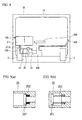
- the relief valve 35 is provided in the fuel return pipe 34. As depicted in FIGs. 9(a) and 9(b) , specifically, the relief valve 35 includes a valve body 351 and a spring 352.
- the valve body 351 forms and blocks the flow path.
- the spring 352 urges the valve body 351 towards the fuel pipe 31B to form the flow path.
- the spring 352 contracts in accordance with the fuel pressure in the fuel pipe 31B. Specifically, when the fuel pressure in the fuel pipe 31B is equal to or higher than a predetermined value, the spring 352 contracts so that the valve body 351 blocks the flow path, as depicted in FIG. 9(a) .
- the spring 352 expands against the fuel pressure so that the valve body 351 forms the flow path, as depicted in FIG. 9(b) .
- the relief valve 35 is closed when the fuel pressure in the fuel pipe 31B is equal to or higher than the predetermined value, and is opened when the fuel pressure is lower than the predetermined value to form the flow path and allow fuel to flow through the flow path.
- the relief valve 35 corresponds to relief means.
- the ECU 50B on the vehicle side is substantially the same as the ECU 50A on the vehicle side except that the fuel pump 33 is electrically connected instead of the open/close valve 32, and the estimate means and the operation control means are not realized, and that control means is realized as described below.
- the ECU 50B on the vehicle side realizes control means to control the fuel pump 33 instead of the open/close valve 32.
- the control means is realized so as to control the fuel pump 33 to perform and stop a fuel supply to the engine 111 by executing a drive control and stop control to the fuel pump 33 in response to an operation request to the generator unit 11B.
- step S11 determines whether an operation request to the generator unit 11B is issued.
- step S12 the ECU 50B on the vehicle side drives the fuel pump 33 (step S12). This starts a fuel supply to the engine 111 from the fuel tank 30B on the vehicle side. Further, the fuel pressure in the fuel pipe 31B becomes equal to or higher than the predetermined value, and the relief valve 35 is closed.
- the ECU 50B on the vehicle side determines whether an operation request to the generator unit 11B is issued (step S13). When a negative determination is made, the ECU 50B ends the present flowchart once. In contrast, when a positive determination is made, the ECU 50B on the vehicle side stops driving the fuel pump 33 (step S14). This stops supplying fuel to the engine 111 from the fuel tank 30B on the vehicle side, and fuel is thus supplied intermittently. Also, the fuel pressure in the pressure in the fuel pipe 31B becomes lower than the predetermined value, and the relief valve 35 is thus opened.
- the electrically driven vehicle 1B is also configured to have the fuel tank 30B on the vehicle side to the vehicle body 10.
- the electrically driven vehicle 1B is capable of ensuring the degree of freedom of the mounted position of the generator unit 11B while ensuring the convenience of refuel, and is further capable of improving the convenience of coping with a shortage of energy of the battery as well as the electrically driven vehicle 1A.
- the engine 111 out of parts of the generator unit 11B is detachably mounted.
- the generator unit 11B cannot be operated solely after it is removed from the vehicle body 10, or the battery 12 cannot be charged remotely.
- the load of the installation or removal work on the generator unit 11B is reduced mainly in terms of weight.
- the fuel tank 30B on the vehicle side is provided to the vehicle body 10 in such a manner the engine 111 out of the parts of the generator unit 11 B rather than the whole generator unit 11B is detachably mounted, the engine 111 being needed to have a fuel supply from the outside like the electrically driven vehicle 1B, for example.
- the electrically driven vehicle 1B In the electrically driven vehicle 1B, a fuel leakage may take place in removal of the engine 111 because the fuel tank 30B on the vehicle side is provided to the vehicle body 10.
- the electrically driven vehicle 1B is configured so that the fuel tank 30B on the vehicle side is provided in a position lower than that of the engine 111, and the fuel pump 33 capable of pumping fuel to the engine 111 from the fuel tank 30B on the vehicle side and that the fuel return pipe 34 and the relief valve 35 are provided. Therefore, the electrically driven vehicle 1B is capable of removing, from the fuel pipe 31B, the residual fuel that may cause a fuel leakage in removal of the engine 111.
- the electrically driven vehicle 1B is capable of preventing the occurrence of a fuel leakage in removal of the engine 111 due to the attachment of the fuel tank 40B on the vehicle side to the vehicle body 10.
- the electrically driven vehicle 1B may be varied so that the whole generator unit is detachably mounted like the electrically driven vehicle 1C depicted in FIG. 11 , for example.
- a generator unit 11C is mounted instead of the generator unit 11B.
- the electrically driven vehicle 1C is provided with a fuel pipe 31C, which detachably connects the fuel tank 114 of the generator unit 11C and the fuel tank 30B on the vehicle side together.
- the fuel pump 33 corresponds to fuel pump means capable of pumping fuel to the fuel tank 114 on the generator unit side from the fuel tank 30B on the vehicle side.
- a detachably attached part 311B is provided to the fuel pipe 31C like the fuel pipe 31B.
- the open/close valve 32 is provided to a portion of the fuel pipe 31C closer to the fuel tank 114 on the generator unit side than the detachably attached part 311B as means for permitting and inhibiting a passage of fuel.
- the open/close valve 32 is provided in the generator unit 11C, and the electrically driven vehicle 1C is configured so that the open/close valve 32 is electrically connected to the ECU 113 on the generator unit side.
- the generator unit 11C is configured by adding the open/close valve 32 to the generator unit 11A.
- the electrically driven vehicle is equipped with the ECU 50C on the vehicle side substituted for the ECU 50B on the vehicle side.
- the ECU 50C on the vehicle side functionally realizes control means that controls the open/close valve 32 and the fuel pump 33 to intermittently supply fuel to the fuel tank 114 on the generator unit side, and functionally realizes estimate means in a similar manner to that realized by the ECU 50A on the vehicle side.
- the control means is functionally realized to intermittently supply fuel to the fuel tank 114 on the generator unit side by controlling the open/close valve 32 to be opened in association with the drive control of the fuel pump 33, and to be closed in association with the stop control of the fuel pump 33.
- the open/close valve 32 is structured to be controlled by the ECU 50C on the vehicle side via the ECU 113 on the generator unit side.
- the electrically driven vehicle 1C is also capable of ensuring the degree of freedom of the mounted position of the generator unit 11C while ensuring the convenience of refuel, and is further capable of improving the convenience of coping with a shortage of energy of the battery. Further, the electrically driven vehicle 1C is capable of preventing the occurrence of a fuel leakage in removal of the generator unit 11C.
- first and second embodiments are preferred exemplary embodiments of the invention.
- the present invention is not limited to those embodiments but may be varied variously without departing from the essentials of the present invention.
- first embodiment a case has been described where the fuel tank 30A on the vehicle side is provided in a position higher than that of the fuel tank 114 on the generator unit side because the first embodiment has a suitable arrangement in which fuel is supplied under its own weight from the fuel tank 30A on the vehicle side to the fuel tank 114 on the generator unit side.
- the present invention is not necessarily limited to the above, but may have another exemplary arrangement in which the first fuel tank is provided in a position lower than that of the second fuel tank.
- the flow change means may be fuel pumping means that is provided in the first fuel tank and is capable of pumping fuel to the second fuel tank from the first fuel tank.
- each ECU 50 on the vehicle side in the first and second embodiments may be realized by hardware such as another electronic control unit and a dedicated electronic circuit or its combination.
Landscapes
- Engineering & Computer Science (AREA)
- Transportation (AREA)
- Mechanical Engineering (AREA)
- Chemical & Material Sciences (AREA)
- Combustion & Propulsion (AREA)
- Life Sciences & Earth Sciences (AREA)
- Sustainable Development (AREA)
- Sustainable Energy (AREA)
- Power Engineering (AREA)
- Cooling, Air Intake And Gas Exhaust, And Fuel Tank Arrangements In Propulsion Units (AREA)
- Electric Propulsion And Braking For Vehicles (AREA)
- Hybrid Electric Vehicles (AREA)
Abstract
Description
- The present invention relates to electrically driven vehicles, and more particularly, to an electrically driven vehicle equipped with a battery usable for running.
- Conventionally, there is known an electrically driven vehicle equipped with a battery usable for running. Such an electrically driven vehicle has a limited cruising range that depends on the amount of charge in the battery. In this regard, there is known an electrically driven vehicle in which a generator unit that charges the battery is further mounted (see Patent Document 1).
The case where the generator unit is mounted needs a supply of fuel thereto. In this regard,Patent Documents
Patent Document 4 discloses an art that may relate to the present invention in light of a fuel tank that is refueled from the outside of the vehicle.
Patent Documents 5 through 7 disclose arts that may relate to the present invention in light of the refuel from the fuel tank. -
- Patent Document 1: Japanese Patent Application Publication No.
10-117404 - Patent Document 2: Japanese Patent Application Publication No.
2007-116788 - Patent Document 3: Japanese Patent Application Publication No.
2004-19565 - Patent Document 4: Japanese Utility Model Registration No.
3123731 - Patent Document 5: Japanese Patent Application Publication No.
2003-341797 - Patent Document 6: Japanese Patent Application Publication No.
2001-295715 - Patent Document 7: Japanese Patent application Publication No.
2001-20818 - In the electric vehicle equipped with the generator unit disclosed in
Patent Document 1, the generator unit is constantly mounted when the vehicle is in use. Therefore, the electric vehicle has an increase in weight that corresponds to the generator unit, and has a degraded energy efficiency.
In contrast to this, it is conceivable that the generator unit (which may be an engine driven type of generator unit or a fuel cell type of generator unit) is detachably mounted in the vehicle, for example. In this case, the generator unit is removed as necessary, and the degradation of the energy efficiency resulting from the increased weight can be suppressed. - In the case where the generator unit is detachably mounted, there is an issue of the method for supplying fuel to the generator unit. In the detachable mounting of the generator unit, it is conceivable to provide a fuel tank in the generator unit, for example. Even in the case where the generator unit is detachably mounted, there is no need to detachably mount a fuel supply system for supplying fuel from the fuel tank, so that the occurrence of fuel leakage in removal or installation of the generator unit can be surely prevented. Also, in this case, it is possible to attempt to realize a simplified structure by arranging the structure so as to directly supply fuel to the fuel tank in the generator unit from the outside of the vehicle in a state in which the generator unit is mounted in the vehicle. Further, in this case, the generator unit removed from the vehicle can be operated solely, and the battery may be charged remotely.
- However, in this case, the mounted position of the generator unit such as a position under the floor of the vehicle may degrade the convenience of the fuel supply from the outside. On the contrary, the mounted position of the generator unit may be limited in order to secure the convenience of the fuel supply from the outside. Such limitation is inconvenient for ensuring a certain degree of freedom of designing the whole vehicle. In this regard, it is conceivable that a supply of fuel to the fuel tank of the generator unit from the outside may be carried out after the generator unit is removed from the vehicle. However, this case needs work to remove the generator unit and degrades the convenience.
- In the case where the generator unit is equipped with the fuel tank, the capacity of the fuel tank may be limited to a certain extent in light of weight and handling because the fuel tank is detachably mounted in the generator unit. Therefore, the case may need refuel more frequently and may degrade the convenience. Further, the present case has a limited total amount of generation of energy that can be ensured at maximum without new refuel from the outside. Thus, the present case has a further problem because in a certain usage environment of the electrically driven vehicle, it is not felt that the amount of generation of energy that can be ensured at maximum is sufficient to make up for the shortage of energy of the battery.
- The present invention was made in view of the above problems, and aims at providing an electrically driven vehicle with a generator unit being detachably mounted, capable of ensuring a certain degree of freedom of the mounted position of the generator unit while ensuring the convenience of a supply of fuel from the outside and improving the convenience of coping with a shortage of energy of the battery.
- The present invention for solving the above problems is an electrically driven vehicle comprising: a vehicle body; a battery that is mounted in the vehicle body and is usable for running; and a generator unit that is detachably mounted in a vehicle body and charges the battery, a first fuel tank that stores fuel supplied to the generator unit being provided in the vehicle body.
- Also, the present invention is preferably configured so that the generator unit includes a second fuel tank that stores fuel for the generator unit; and a fuel supply system is provided so as to detachably connect the first and second fuel tanks together.
- Also, the present invention is preferably configured so that the fuel supply system is connected to the second fuel tank so that fuel supplied is poured into the second fuel tank; and the electrically driven vehicle further comprising: flow change means capable of changing a flow state of fuel passing through the fuel supply system; control means for controlling the flow change means so as to intermittently supply the fuel to the second fuel tank; and operation control means for making the generator unit temporarily operate when the control means controls the flow change means to intermittently supply the fuel to the second fuel tank.
- Also, the present invention is preferably configured so that the first fuel tank is provided in a position lower than that of the second fuel tank, and a detachably attached part that makes it possible to attach and detach the first fuel tank and the second fuel tank to and from each other is provided to a portion of the fuel supply system extending to the second fuel tank from a lower side thereof, switch means capable of allowing the fuel to pass and inhibiting the fuel from passing being provided to another portion of the fuel supply system closer to the second fuel tank than the detachable attached part; and the electrically driven vehicle further comprises: fuel pumping means that is provided in the first fuel tank and is capable of pumping the fuel from the first fuel tank to the second fuel tank; control means for controlling the fuel pumping means and the switch means so as to intermittently supply the fuel to the second fuel tank; a fuel return system that has one end connected to a portion of the fuel supply system closer to the first fuel tank than the detachably attached part and another end connected to the first fuel tank, and is provided so that the fuel flows under its own weight from the fuel supply system to the first fuel tank; and relief means, provided in the fuel return system, for increasing the fuel passing therethrough in accordance with a pressure of the fuel in the fuel supply system when the pressure of the fuel is lower than a predetermined value.
- Also, the present invention is preferably configured so as to further comprise estimate means for estimating an amount of fuel remaining in the second fuel tank on the basis of an operation state of the generator unit.
- Also, the present invention is preferably configured so that a wall portion of a housing of the generator unit is included in at least part of a wall portion that forms the second fuel tank.
- Also, the present invention is preferably configured so that the generator unit is an engine driven type of generator unit; and a fuel supply system is provided so as to detachably mount the engine of the generator unit and to detachably connect the first fuel tank and the engine together.
- Also, the present invention is preferably configured so that the first fuel tank is provided in a lower higher than that of the engine, and a detachably attached part that makes it possible to attach and detach the first fuel tank and the engine to and from each other is provided to a portion of the fuel supply system extending to the engine from a lower side thereof; and the electrically driven vehicle further comprises: fuel pumping means that is provided in the first fuel tank and is capable of pumping the fuel from the first fuel tank to the engine; control means for controlling the fuel pumping means so as to supply the fuel to the engine and stop supplying the fuel to the engine; a fuel return system that has one end connected to a portion of the fuel supply system closer to the first fuel tank than the detachably attached part and another end connected to the first fuel tank, and is provided so that the fuel flows under its own weight from the fuel supply system to the first fuel tank; and relief means, provided in the fuel return system, for increasing the fuel passing therethrough in accordance with a pressure of the fuel in the fuel supply system when the pressure of the fuel is lower than a predetermined value.
- According to the present invention, it is possible to ensure a certain degree of freedom of the mounted position of the generator unit while ensuring the convenience of a supply of fuel from the outside and to improve the convenience of coping with a shortage of energy of the battery.
-
-
FIG. 1 is a diagram of a schematic structure of an electrically driven vehicle in accordance with a first embodiment; -
FIG. 2 is a diagram of a generator unit in accordance with the first embodiment; -
FIG. 3 is a cross-sectional view taken along a line A-A inFIG. 2 ; -
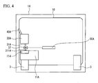
FIG. 4 is a schematic diagram of parts of the electrically driven vehicle in accordance with the first embodiment; -
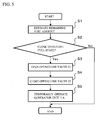
FIG. 5 is a flowchart of an operation of an ECU (Electronic control unit) in accordance with the first embodiment; -
FIG. 6 is a diagram of a first variation of the electrically driven vehicle in accordance with the first embodiment; -
FIG. 7 is a diagram of a second variation of the electrically driven vehicle in accordance with the first embodiment; -
FIG. 8 is a diagram of parts of an electrically driven vehicle in accordance with an embodiment; -
FIGs. 9(a) and 9(b) are diagrams of a relief valve in whichFIG. 9(a) illustrates the relief valve when it is closed, andFIG. 9(b) illustrates the relief valve when it is opened; -
FIG. 10 is a flowchart of an operation of an ECU on the vehicle side in accordance with a second embodiment; and -
FIG. 11 is a diagram of a variation of the electrically driven vehicle in accordance with the second embodiment. - Now, a description is given of modes for carrying out the invention in conjunction with the drawings.
- First, a first embodiment is described. Referring to
FIG. 1 , an electrically drivenvehicle 1A has avehicle body 10 in which agenerator unit 11A, abattery 12, and anelectric motor 13 are mounted. The electrically drivenvehicle 1A is configured so that thegenerator unit 11 A is detachably mounted. The electrically drivenvehicle 1A capable of detachably installing thegenerator unit 11A can be operated in a state in which thegenerator unit 11A is not mounted and is electrically disconnected. - The
generator unit 11A is an engine driven type of generator unit, and is equipped, as illustrated inFIG. 2 , with anengine 111, agenerator 112, anECU 113, and afuel tank 114 on the generator unit side. Theengine 111 drives thegenerator unit 112, which generates alternating current. Then, the alternating current thus generated is converted to direct current by a not-illustrated rectifying circuit before being charged in thebattery 12. TheECU 113 on the generator unit side is provided for primarily controlling theengine 111. Thefuel tank 114 on the generator unit side is connected to theengine 111 so that fuel can be supplied thereto, and stores fuel for thegenerator unit 11A (specifically, engine 111). As illustrated inFIG. 3 , part of awall portion 114a that forms thefuel tank 114 on the generator unit side is a wall portion of ahousing 115 of thegenerator unit 11A. In this regard, specifically, thegenerator unit 11A is detachably mounted under the floor, and the part of the wall portion is an element that defines the overall height of thegenerator unit 11A in the mounted attitude. Thefuel tank 114 on the generator unit side corresponds to the second fuel tank. - As illustrated in
FIG. 1 , thebattery 12 is a direct current battery, and is electrically and detachably connected to thegenerator unit 11A via high-voltage system wires that are power-system wires. Energy generated by thegenerator unit 11A is stored in thebattery 12 via the high-voltage system wires. Thebattery 12 may be configured to have multiple batteries having a rated DC voltage of 12 V connected in series, for example. Theelectric motor 13 is a source for running, and is a DC motor. Theelectric motor 13 is supplied with energy from thebattery 12, and rotates anoutput shaft 14. Then, the rotary output is transmitted, via atransmission 15, to a pair of right and leftrear wheels 2, which are driving wheels, so that therear wheels 2 can be driven. As described above, the electrically drivenvehicle 1A is a series hybrid type of electrically driven vehicle. - The electrically driven
vehicle 1A is equipped, in addition to the pair of right and leftrear wheels 2 of the driving wheels, with a pair of right and leftfront wheels 3 that are steering wheels, ahandle 4 for manually steering thefront wheels 3, anacceleration pedal 5 for changing the number of revolutions of theelectric motor 13, a brake pedal 6 and abrake unit 7 for braking the vehicle, anddrum brakes 8 coupled with the brake pedal 6 by wires, joined to thebrake unit 7 and provided to thefront wheels 3 and therear wheels 2. Theacceleration pedal 5 is provided with an acceleration position sensor 26 that senses the amount of depression of theacceleration pedal 5, and the brake pedal 6 is provided with abrake switch 62 that senses whether the brake pedal 6 is depressed or not. - The electrically driven
vehicle 1A is further provided with akey switch 21. Thekey switch 21 is a switch that enables selective switching operation between ON and OFF. Thekey switch 21 is vehicle drive operation means realized to make an operation request to thegenerator unit 11A and theelectric motor 13. Specifically, when thekey switch 21 is ON, the operation request to theelectric motor 13 is made. When thekey switch 21 is OFF, the operation request to theelectric motor 13 is not made. Operation means for making an operation request to thegenerator unit 11A may be provided separately from thekey switch 21, for example. - As illustrated in
FIG. 4 , the electrically drivenvehicle 1A is further equipped with afuel tank 30A on the vehicle side, afuel pipe 31A, an open/close valve 32 and anoil supply port 40A. Thefuel tank 30A on the vehicle side is provided on thevehicle body 10. Thefuel tank 30A on the vehicle side is a fuel tank from which oil is supplied from the outside of the vehicle, and stores fuel that is to be supplied to thefuel tank 114 on the generator unit side. Thefuel tank 30A on the vehicle side is provided in a position higher than that of thefuel tank 114 on the generator unit side. Thefuel tank 30A on the vehicle side corresponds to a first fuel tank. - The
fuel pipe 31A is provided so as to detachably connect thefuel tank 30A on the vehicle side and thefuel tank 114 on the generator unit side together. Specifically, one end of thefuel pipe 31A is connected to thefuel tank 30A on the vehicle side, and the other end thereof is detachably connected to thefuel tank 114 on the generator unit side as a detachably attachedpart 311A that makes it possible to attach and detach thefuel tank 30A on the vehicle side and thefuel tank 114 on the generator unit side to and from each other. Thefuel pipe 31A is connected to thefuel tank 114 on the generator unit side so that supplied fuel is poured in thefuel tank 114 on the generator unit side. Specifically, the other end of thefuel pipe 31A is connected to an upper surface of thefuel tank 114 on the generator unit side. Thefuel pipe 31A corresponds to a fuel supply system. - The open/
close valve 32 is an electromagnetic valve capable of changing the flow state of fuel that passes through thefuel pipe 31A. Specifically, the open/close valve 32 changes the flow state of fuel through the fuel pipe by forming the flow path of thefuel pipe 31A to allow the fuel to pass through thefuel pipe 31A when it is opened and by blocking the flow path of thefuel pipe 31A to stop the fuel from passing through thefuel pipe 31A when it is closed. The open/close valve 32 is provided on thevehicle body 10 side, and is specifically provided to thefuel pipe 31A in a position closer to thefuel tank 30A than the other end of thefuel pipe 31A to which the detachably attachedpart 311A is provided. The open/close valve 32 corresponds to flow change means.
Theoil supply port 40A is a fuel supply port from the outside, and is provided to thevehicle body 10. Theoil supply port 40A communicates with thefuel tank 30A on the vehicle side, and oil is supplied to thefuel tank 30A on the vehicle side via theoil supply port 40A. - As illustrated in
FIG. 1 , the electrically drivenvehicle 1A is equipped with anECU 50A, which is a first control unit. TheECU 50A on the vehicle side is equipped with a microcomputer composed of a CPU, a ROM, a RAM and so on, and an input/output circuit, which are not illustrated. TheECU 113 on the generator unit side, which is a second control unit, is configured similarly. Thegenerator unit 11A (more specifically, theECU 113 on the generator unit side) is electrically and detachably connected to theECU 50A on the vehicle side. In this regard, theECU 50A on the vehicle side and thegenerator unit 11A are connected together via low-voltage system wires, which are control-system wires. Various objects to be controlled such as theelectric motor 13 and the open/close valve 32 (seeFIG 4 ) are electrically connected to theECU 50A on the vehicle side, and further, various sensors and switches such as thekey switch 21, theacceleration position sensor 61 and thebrake switch 62 are electrically connected thereto. - The ROM is configured to store a program in which various processes executed by the CPU are described and to store map data. The CPU executes the processes on the basis of the program stored in the ROM while using a temporary memory area ensured in the RAM as necessary, so that various control means, determination means, detection means and calculation means can be functionally realized in the
ECU 50A on the vehicle side and theECU 113 on the generator unit side. - In this regard, for example, the
ECU 50A on the vehicle side functionally realizes control means that controls the open/close valve 32. Specifically, the control means is realized so as to control the open/close valve 32 to intermittently supply fuel to thefuel tank 114 on the generator unit side from thefuel tank 30A on the vehicle side by performing the combination of a control to open the open/close valve 32 and a control to close the open/close valve 32.
In the control of the open/close valve 32, theECU 50A on the vehicle side functionally realizes estimate means that estimates the amount of remaining fuel stored in thefuel tank 114 on the generator unit side on the basis of the operating state of thegenerator unit 11A.
Specifically, the estimate means is realized so as to estimate whether the remaining fuel amount is close to an out-of-fuel state by determining whether an abnormality showing an out-of-fuel indication occurs in thegenerator unit 11A on the basis of the operating state of thegenerator unit 11A (for example, the number of revolutions of theengine 111 and the magnitude of energy generated by thegenerator unit 11A).
Specifically, the control means is realized so as to control the open/close valve 32 when it is determined that the remaining amount of fuel is close to the out-of-fuel state on the basis of the remaining fuel amount estimated by the estimate means. - For example, the
ECU 50A on the vehicle side functionally realizes operation control means for temporarily operating thegenerator unit 11A in a case where the control means controls the open/close valve 32 to intermittently supply fuel to thefuel tank 114 on the generator unit side.
In the temporary operation of thegenerator unit 11A, specifically, the operation control means is realized so as to temporarily operate thegenerator unit 11A under a condition that makes it possible to remove fuel remaining in a portion of thefuel pipe 31A closer to thefuel tank 114 on the generator unit side other than the open/close valve 32 through which fuel supplied is poured in thefuel tank 114 on the generator unit side irrespective of whether an operation request to thegenerator unit 11A is issued (hereinafter, referred to as a fuel removal operation condition). The intermittent operation of thegenerator unit 11 A under the fuel removal operation condition may be implemented by operating thegenerator unit 11A for a predetermined time under a predetermined operating condition. - Now, a description is given, in conjunction with a flowchart of
FIG. 5 performed by theECU 50A on the vehicle side, of an operation of theECU 50A on the vehicle side. The present flowchart is repetitively executed at very short intervals while thegenerator unit 11A mounted in the vehicle is operating. TheECU 50A on the vehicle side estimates the amount of fuel remaining in thefuel tank 114 on the generator unit side on the basis of the operating state of thegenerator unit 11A (step S1). Next, theECU 50A on the vehicle side determines whether the remaining fuel amount is close to the out-of-fuel state on the basis of the estimated amount of remaining fuel (step S2). When a negative determination is made in step S2, no specific process is needed and the flowchart is ended. In contrast, when a positive determination is made in step S2, theECU 50A on the vehicle side opens the open/close valve 32 (step S3). Thus, a fuel supply from thefuel tank 30A on the vehicle side to thefuel tank 114 on the generator unit side is started. Subsequently, theECU 50A on the vehicle side closes the open/close valve 32 (step S4). This stops supplying fuel to thefuel tank 114 on the generator unit side form thefuel tank 30A on the vehicle side, and intermittently supplies fuel. The timing at which the open/close valve 32 is closed may be controlled appropriately based on time, for example. Then, theECU 50A on the vehicle side temporarily operates thegenerator unit 11A under the fuel removal operation condition (step S5). - Next, a description is given of functions and effects of the electrically driven
vehicle 1A. In the electrically drivenvehicle 1A, thefuel tank 30A on the vehicle side is provided to thevehicle body 10. Thus, in the electrically drivenvehicle 1A, theoil supply port 40A can be provided to thevehicle body 10 without being specifically affected by the mounted position of thegenerator unit 11A in such a manner that thefuel tank 30A on the vehicle side is a fuel tank to be refueled. Thus, the electrically drivenvehicle 1A is capable of ensuring the degree of freedom of the mounted position of thegenerator unit 11A while ensuring the convenience of refuel.
The electrically drivenvehicle 1A is capable of ensuring a larger tank capacity by providing thevehicle body 10 with thefuel tank 30A on the vehicle side. Thus, the electrically drivenvehicle 1A is capable of having a larger amount of fuel per one refueling and ensuring the convenience of refuel including a reduced frequency of refuel.
The electrically drivenvehicle 1A has a larger tank capacity, and is thus capable of ensuring a larger total amount of energy that can be generated by thegenerator unit 11A without new refuel than the amount of energy that can be ensured at maximum by theoriginal generator unit 11A. Thus, the electrically drivenvehicle 1A has improved convenience of coping with a shortage of energy of the battery. - In the electrically driven
vehicle 1A, thefuel tank 114 on the generator unit side is provided to thegenerator unit 11A Therefore, thegenerator unit 11A can be operated solely after it is removed from the electrically drivenvehicle 1A in which thefuel tank 30A on the vehicle side is provided to thevehicle body 10, and thebattery 12 can be charged remotely. Specifically, thebattery 12 can be charged by thegenerator unit 11A that is electrically connected to the electrically drivenvehicle 1A even when thegenerator unit 11A is not mounted in thevehicle body 10 by further providing inhibiting means for inhibiting controls of the control means, estimate means and operation control means. - The
fuel tank 30A provided to thevehicle body 10 of the electrically drivenvehicle 1A may cause fuel leakage in removal of thegenerator unit 11A. With respect to this, in the electrically drivenvehicle 1A, thefuel pipe 31A is connected to thefuel tank 114 on the generator unit side so that fuel supplied is poured into thefuel tank 114 on the generator unit side. Further, thegenerator unit 11A is temporarily operated under the fuel removal operation condition in the case where fuel is intermittently supplied to thefuel tank 114 on the generator unit side from thefuel tank 30A on the vehicle side. It is thus possible to remove fuel remaining in thefuel pipe 31A that may cause fuel leakage in removal of thegenerator unit 11A from the electrically drivenvehicle 1A. In the electrically drivenvehicle 1A, thefuel tank 30A on the vehicle side is provided to thevehicle body 10, whereby the occurrence of fuel leakage can further be prevented in removal of thegenerator unit 11A. - In the electrically driven
vehicle 1A, thefuel tank 30A on the vehicle side is provided in a position higher than that of thefuel tank 114 on the generator unit side. Thus, in the electrically drivenvehicle 1A, fuel is supplied under its own weight from thefuel tank 30A on the vehicle side to thefuel tank 114 on the generator unit side. Thus, the electrically drivenvehicle 1A has an economically advantageous structure because it does not need any fuel pump for supplying fuel from thefuel tank 30A on the vehicle side to thefuel tank 114 on the generator unit side. - The electrically driven
vehicle 1A estimates the amount of fuel remaining in thefuel tank 114 on the generator unit side on the basis of the operating state of thegenerator unit 11A. Thus, the electrically drivenvehicle 1A has an economically advantageous structure because it does not need for sensing of the remaining amount of fuel in the supply of fuel from thefuel tank 30A on the vehicle side to thefuel tank 114 on the generator unit side. - In the electrically driven
vehicle 1A, thefuel tank 30A on the vehicle side is provided to thevehicle body 10. Thus, as compared with the case where refuel is performed directly from thefuel tank 114 on the generator unit side, the mounted position of thegenerator unit 11A may be determined without any particular limitation in view of the convenience of refuel. In this regard, the electrically drivenvehicle 1A is configured so that part of thewall portion 114a that forms thefuel tank 114 on the generator unit side is the wall portion of thehousing 115 of thegenerator unit 11 A. Thus, in the electrically drivenvehicle 1A, thegenerator unit 11A may be made compact, and thegenerator unit 11A may easily be mounted on a limited mounting space such as under the floor of the vehicle Thus, the electrically drivenvehicle 1A has a higher degree of freedom of selection of the mounted position of thegenerator unit 11A in addition to no limitation resulting from the convenience of refuel. - The electrically driven
vehicle 1A may be varied so as to detachably mount a plurality ofgenerator units 11A. In this case, like an electrically drivenvehicle 1A' illustrated inFIG. 6 , for example, afuel pipe 31A' may be substituted for thefuel pipe 31A, in which thefuel pipe 31A' has an end connected to thefuel tank 30A on the vehicle side, and branches into other ends respectively connected to a plurality of (two in this case)fuel tanks 114 on the generator unit side. In this case, the open/close valves 32 may be provided in branch portions of thefuel pipes 31A' through which fuel supplied is poured into thefuel tanks 114. Attaching and detachingparts 311A may be provided in portions of thefuel pipes 31A' closer to thefuel tanks 114 on the generator unit side than the open/close valves 32 (the other ends in this case). This makes it possible to supply fuel to thefuel tanks 114 on the generator unit side from thefuel tank 30A on the vehicle side even when the plurality ofgenerator units 11A are detachably mounted. - Like an electrically driven
vehicle 1A" depicted inFIG. 7A , for example, the detachable mounting of the plurality ofgenerator units 11A may be configured to detachably provide acommunication pipe 45, which makes thefuel tank 114 of thegenerator unit 11A that receives fuel from thefuel tank 30A on the vehicle side and thefuel tank 114 of eachother generator unit 11A or each engine to communicate with each other. Thecommunication pipe 45 may be detachably provided by usingcouplers 45a attached to detachable portions. This makes it possible to supply fuel to eachfuel tank 114 of eachgenerator unit 11A from thefuel tank 30A on the vehicle side. Thecommunication pipe 45 is preferably provided so that fuel is evenly stored in thefuel tanks 114 on the generator unit side. The electrically drivenvehicle 1A" is capable of supplying fuel to theengines 111 of thegenerator units 11A by only a single fuel pump and realizing cost reduction and fuel economy. - Next, a second embodiment is described. As depicted in
FIG. 8 , an electrically drivenvehicle 1B in accordance with the present embodiment is substantially the same as the electrically drivenvehicle 1A except that thevehicle 1B is equipped with agenerator unit 11B substituted for thegenerator unit 11A, afuel tank 30B on the vehicle side substituted for thefuel tank 30A on the vehicle side, afuel pipe 31B for thefuel pipe 31A, anoil supply port 40B for theoil supply port 40A, and afuel pump 33 for the open/close valve 32, and is further equipped with afuel return pipe 34 and arelief valve 35 and that thevehicle 1B is equipped with anECU 50B on the vehicle side instead of the ECU soya on the vehicle side. - The
generator unit 11B is substantially the same as thegenerator unit 11A except that theengine 111 of thegenerator unit 11B is configured to be detachably mounted and thefuel tank 114 on the generator unit side is not provided. Thefuel tank 30B on the vehicle side is substantially the same as thefuel tank 30A on the vehicle side except that thefuel pump 33 is provided within thegenerator unit 11B. The electrically drivenvehicle 1B is configured so that thegenerator unit 11B and thefuel tank 30B on the vehicle side are arranged in such a manner that thefuel tank 30B on the vehicle side is provided in a position lower than that of theengine 111. Afuel pipe 31B is provided so as to detachably connect thefuel tank 30B on the vehicle side and theengine 111 together. A detachably attachedpart 311 B for enabling thefuel tank 30B on the vehicle side and theengine 111 to be attached to or detached from each other is provided in a portion of thefuel pipe 31B connected to theengine 111 from the lower side. Thefuel supply port 40B has an arrangement different from that of thefuel supply port 40B, and makes the outside of the electrically drivenvehicle 1B and thefuel tank 30A communicate with each other. - The
fuel pump 33 is configured to supply fuel to theengine 111 from thefuel tank 30B on the vehicle side with pressure. Specifically, thefuel pump 33 pumps fuel, which flows through thefuel pipe 31 B and is then supplied to theengine 111 when thefuel pump 33 is driven. When thefuel pump 33 is stopped to cease pumping, the fuel stops flowing through thefuel pipe 31B, so that a fuel supply to theengine 111 is stopped. Thefuel pump 33 corresponds to fuel pumping means and may be understandable as flow changing means.
Afuel return pipe 34 is provided so that one end is connected to a portion of thefuel pipe 31B closer to thefuel tank 30B on the vehicle side than the detachably attachedpart 311B, and the other end is connected to thefuel tank 30B on the vehicle side, whereby fuel is supplied under its own weight from thefuel pipe 31B to thefuel tank 30B on the vehicle side. Thefuel return pipe 34 corresponds to a fuel return system. - The
relief valve 35 is provided in thefuel return pipe 34. As depicted inFIGs. 9(a) and 9(b) , specifically, therelief valve 35 includes avalve body 351 and aspring 352. Thevalve body 351 forms and blocks the flow path. Thespring 352 urges thevalve body 351 towards thefuel pipe 31B to form the flow path. Thespring 352 contracts in accordance with the fuel pressure in thefuel pipe 31B. Specifically, when the fuel pressure in thefuel pipe 31B is equal to or higher than a predetermined value, thespring 352 contracts so that thevalve body 351 blocks the flow path, as depicted inFIG. 9(a) . In contrast, when the fuel pressure in thefuel pipe 31B is lower than the predetermined value, thespring 352 expands against the fuel pressure so that thevalve body 351 forms the flow path, as depicted inFIG. 9(b) . Therelief valve 35 is closed when the fuel pressure in thefuel pipe 31B is equal to or higher than the predetermined value, and is opened when the fuel pressure is lower than the predetermined value to form the flow path and allow fuel to flow through the flow path. Thus, it is possible to increase the flow rate of fuel that is allowed to flow. Therelief valve 35 corresponds to relief means. - The
ECU 50B on the vehicle side is substantially the same as theECU 50A on the vehicle side except that thefuel pump 33 is electrically connected instead of the open/close valve 32, and the estimate means and the operation control means are not realized, and that control means is realized as described below.
TheECU 50B on the vehicle side realizes control means to control thefuel pump 33 instead of the open/close valve 32. Specifically, the control means is realized so as to control thefuel pump 33 to perform and stop a fuel supply to theengine 111 by executing a drive control and stop control to thefuel pump 33 in response to an operation request to thegenerator unit 11B. - Now, a description is given of an operation of the
ECU 50B on the vehicle side in conjunction with a flowchart ofFIG. 10 . TheECU 50B on the vehicle side determines whether an operation request to thegenerator unit 11B is issued (step S11). When a negative determination is made, theECU 50B ends the present flowchart once. In contrast, when a positive determination is made in step S11, theECU 50B on the vehicle side drives the fuel pump 33 (step S12). This starts a fuel supply to theengine 111 from thefuel tank 30B on the vehicle side. Further, the fuel pressure in thefuel pipe 31B becomes equal to or higher than the predetermined value, and therelief valve 35 is closed. Then, theECU 50B on the vehicle side determines whether an operation request to thegenerator unit 11B is issued (step S13). When a negative determination is made, theECU 50B ends the present flowchart once. In contrast, when a positive determination is made, theECU 50B on the vehicle side stops driving the fuel pump 33 (step S14). This stops supplying fuel to theengine 111 from thefuel tank 30B on the vehicle side, and fuel is thus supplied intermittently. Also, the fuel pressure in the pressure in thefuel pipe 31B becomes lower than the predetermined value, and therelief valve 35 is thus opened. - Next, a description is given of functions and effects of the electrically driven
vehicle 1B. The electrically drivenvehicle 1B is also configured to have thefuel tank 30B on the vehicle side to thevehicle body 10. Thus, the electrically drivenvehicle 1B is capable of ensuring the degree of freedom of the mounted position of thegenerator unit 11B while ensuring the convenience of refuel, and is further capable of improving the convenience of coping with a shortage of energy of the battery as well as the electrically drivenvehicle 1A.
In the electrically drivenvehicle 1B, theengine 111 out of parts of thegenerator unit 11B is detachably mounted. Thus, in the electrically drivenvehicle 1B, thegenerator unit 11B cannot be operated solely after it is removed from thevehicle body 10, or thebattery 12 cannot be charged remotely. However, the load of the installation or removal work on thegenerator unit 11B is reduced mainly in terms of weight. In terms of a different viewpoint, it may be said that thefuel tank 30B on the vehicle side is provided to thevehicle body 10 in such a manner theengine 111 out of the parts of thegenerator unit 11 B rather than thewhole generator unit 11B is detachably mounted, theengine 111 being needed to have a fuel supply from the outside like the electrically drivenvehicle 1B, for example. - In the electrically driven
vehicle 1B, a fuel leakage may take place in removal of theengine 111 because thefuel tank 30B on the vehicle side is provided to thevehicle body 10. In order to cope with the above, the electrically drivenvehicle 1B is configured so that thefuel tank 30B on the vehicle side is provided in a position lower than that of theengine 111, and thefuel pump 33 capable of pumping fuel to theengine 111 from thefuel tank 30B on the vehicle side and that thefuel return pipe 34 and therelief valve 35 are provided. Therefore, the electrically drivenvehicle 1B is capable of removing, from thefuel pipe 31B, the residual fuel that may cause a fuel leakage in removal of theengine 111. Thus, the electrically drivenvehicle 1B is capable of preventing the occurrence of a fuel leakage in removal of theengine 111 due to the attachment of thefuel tank 40B on the vehicle side to thevehicle body 10. - The electrically driven
vehicle 1B may be varied so that the whole generator unit is detachably mounted like the electrically driven vehicle 1C depicted inFIG. 11 , for example. In the electrically driven vehicle 1C, agenerator unit 11C is mounted instead of thegenerator unit 11B. Further, the electrically driven vehicle 1C is provided with afuel pipe 31C, which detachably connects thefuel tank 114 of thegenerator unit 11C and thefuel tank 30B on the vehicle side together. Thus, thefuel pump 33 corresponds to fuel pump means capable of pumping fuel to thefuel tank 114 on the generator unit side from thefuel tank 30B on the vehicle side. - A detachably attached
part 311B is provided to thefuel pipe 31C like thefuel pipe 31B. The open/close valve 32 is provided to a portion of thefuel pipe 31C closer to thefuel tank 114 on the generator unit side than the detachably attachedpart 311B as means for permitting and inhibiting a passage of fuel. Thus, the open/close valve 32 is provided in thegenerator unit 11C, and the electrically driven vehicle 1C is configured so that the open/close valve 32 is electrically connected to theECU 113 on the generator unit side. Thegenerator unit 11C is configured by adding the open/close valve 32 to thegenerator unit 11A. - The electrically driven vehicle is equipped with the
ECU 50C on the vehicle side substituted for theECU 50B on the vehicle side. TheECU 50C on the vehicle side functionally realizes control means that controls the open/close valve 32 and thefuel pump 33 to intermittently supply fuel to thefuel tank 114 on the generator unit side, and functionally realizes estimate means in a similar manner to that realized by theECU 50A on the vehicle side. Specifically, the control means is functionally realized to intermittently supply fuel to thefuel tank 114 on the generator unit side by controlling the open/close valve 32 to be opened in association with the drive control of thefuel pump 33, and to be closed in association with the stop control of thefuel pump 33. In this regard, the open/close valve 32 is structured to be controlled by theECU 50C on the vehicle side via theECU 113 on the generator unit side. Thus, the electrically driven vehicle 1C is also capable of ensuring the degree of freedom of the mounted position of thegenerator unit 11C while ensuring the convenience of refuel, and is further capable of improving the convenience of coping with a shortage of energy of the battery. Further, the electrically driven vehicle 1C is capable of preventing the occurrence of a fuel leakage in removal of thegenerator unit 11C. - The above-described first and second embodiments are preferred exemplary embodiments of the invention. However, the present invention is not limited to those embodiments but may be varied variously without departing from the essentials of the present invention.
For example, in the above-described first embodiment, a case has been described where thefuel tank 30A on the vehicle side is provided in a position higher than that of thefuel tank 114 on the generator unit side because the first embodiment has a suitable arrangement in which fuel is supplied under its own weight from thefuel tank 30A on the vehicle side to thefuel tank 114 on the generator unit side. However, the present invention is not necessarily limited to the above, but may have another exemplary arrangement in which the first fuel tank is provided in a position lower than that of the second fuel tank. In this case, the flow change means may be fuel pumping means that is provided in the first fuel tank and is capable of pumping fuel to the second fuel tank from the first fuel tank. - The various means functionally realized by each ECU 50 on the vehicle side in the first and second embodiments may be realized by hardware such as another electronic control unit and a dedicated electronic circuit or its combination.
-
- 1A, 1A', 1A", 1B, 1C
- electrically driven vehicle
- 10
- vehicle body
- 11A, 11b, 11C
- generator unit
- 111
- engine
- 114
- fuel tank on a generator unit side
- 12
- battery
- 30A, 30B
- fuel tank on a vehicle side
- 31A, 31A', 31B, 31C
- fuel pipe
- 32
- open/close valve
- 33
- fuel pump
- 34
- fuel return pipe
- 35
- relief valve
- 351
- valve body
- 352
- spring
- 40A, 40B
- oil supply port
- 45
- communication pipe
- 50A, 50B, 50C
- ECU on a vehicle side
Claims (8)
- An electrically driven vehicle comprising:a vehicle body;a battery that is mounted in the vehicle body and is usable for running; anda generator unit that is detachably mounted in the vehicle body and charges the battery,a first fuel tank that stores fuel supplied to the generator unit being provided in the vehicle body.
- The electrically driven vehicle according to claim 1, wherein:the generator unit includes a second fuel tank that stores fuel for the generator unit; anda fuel supply system is provided so as to detachably connect the first and second fuel tanks together.
- The electrically driven vehicle according to claim 2, wherein:the fuel supply system is connected to the second fuel tank so that fuel supplied is poured into the second fuel tank; andthe electrically driven vehicle further comprising:flow change means capable of changing a flow state of fuel passing through the fuel supply system;control means for controlling the flow change means so as to intermittently supply the fuel to the second fuel tank; andoperation control means for making the generator unit temporarily operate when the control means controls the flow change means to intermittently supply the fuel to the second fuel tank.
- The electrically driven vehicle according to claim 2, wherein:the first fuel tank is provided in a position lower than that of the second fuel tank, and a detachably attached part that makes it possible to attach and detach the first fuel tank and the second fuel tank to and from each other is provided to a portion of the fuel supply system extending to the second fuel tank from a lower side thereof, switch means capable of allowing the fuel to pass and inhibiting the fuel from passing being provided to another portion of the fuel supply system closer to the second fuel tank than the detachable attached part; andthe electrically driven vehicle further comprises:fuel pumping means that is provided in the first fuel tank and is capable of pumping the fuel from the first fuel tank to the second fuel tank;control means for controlling the fuel pumping means and the switch means so as to intermittently supply the fuel to the second fuel tank;a fuel return system that has one end connected to a portion of the fuel supply system closer to the first fuel tank than the detachably attached part and another end connected to the first fuel tank, and is provided so that the fuel flows under its own weight from the fuel supply system to the first fuel tank; andrelief means, provided in the fuel return system, for increasing the fuel passing therethrough in accordance with a pressure of the fuel in the fuel supply system when the pressure of the fuel is lower than a predetermined value.
- The electrically driven vehicle according to claim 2, further comprising estimate means for estimating an amount of fuel remaining in the second fuel tank on the basis of an operation state of the generator unit.
- The electrically driven vehicle according to claim 2, wherein a wall portion of a housing of the generator unit is included in at least part of a wall portion that forms the second fuel tank.
- The electrically driven vehicle according to claim 1, wherein:the generator unit is an engine driven type of generator unit; anda fuel supply system is provided so as to detachably mount the engine of the generator unit and to detachably connect the first fuel tank and the engine together.
- The electrically driven vehicle according to claim 7, wherein:the first fuel tank is provided in a position lower than that of the engine, and a detachably attached part that makes it possible to attach and detach the first fuel tank and the engine to and from each other is provided to a portion of the fuel supply system extending to the engine from a lower side thereof; andthe electrically driven vehicle further comprises:fuel pumping means that is provided in the first fuel tank and is capable of pumping the fuel from the first fuel tank to the engine;control means for controlling the fuel pumping means so as to supply the fuel to the engine and stop supplying the fuel to the engine;a fuel return system that has one end connected to a portion of the fuel supply system closer to the first fuel tank than the detachably attached part and another end connected to the first fuel tank, and is provided so that the fuel flows under its own weight from the fuel supply system to the first fuel tank; andrelief means, provided in the fuel return system, for increasing the fuel passing therethrough in accordance with a pressure of the fuel in the fuel supply system when the pressure of the fuel is lower than a predetermined value.
Applications Claiming Priority (1)
| Application Number | Priority Date | Filing Date | Title |
|---|---|---|---|
| PCT/JP2009/070910 WO2011074074A1 (en) | 2009-12-15 | 2009-12-15 | Electric vehicle |
Publications (3)
| Publication Number | Publication Date |
|---|---|
| EP2514622A1 true EP2514622A1 (en) | 2012-10-24 |
| EP2514622A4 EP2514622A4 (en) | 2013-08-07 |
| EP2514622B1 EP2514622B1 (en) | 2014-10-29 |
Family
ID=44166871
Family Applications (1)
| Application Number | Title | Priority Date | Filing Date |
|---|---|---|---|
| EP09852268.3A Not-in-force EP2514622B1 (en) | 2009-12-15 | 2009-12-15 | Electric vehicle |
Country Status (5)
| Country | Link |
|---|---|
| US (1) | US8589008B2 (en) |
| EP (1) | EP2514622B1 (en) |
| JP (1) | JP5282829B2 (en) |
| CN (1) | CN102656045B (en) |
| WO (1) | WO2011074074A1 (en) |
Families Citing this family (6)
| Publication number | Priority date | Publication date | Assignee | Title |
|---|---|---|---|---|
| JP5891774B2 (en) * | 2011-12-22 | 2016-03-23 | 三菱自動車工業株式会社 | Hybrid car |
| JP6196085B2 (en) * | 2013-07-18 | 2017-09-13 | 本田技研工業株式会社 | Vehicle with generator |
| US9880042B2 (en) * | 2015-12-08 | 2018-01-30 | The Boeing Company | Propellant gauging tool for predicting propellant mass in a propellant storage volume |
| CN106515486B (en) * | 2016-11-22 | 2020-02-14 | 中车株洲电力机车有限公司 | Power control system and energy storage vehicle with same |
| CN106379160A (en) * | 2016-11-22 | 2017-02-08 | 中车株洲电力机车有限公司 | Power control system and energy-storing vehicle with system |
| MX2024002810A (en) * | 2021-09-07 | 2024-04-09 | Nissan Motor | METHOD FOR CONTROLLING VEHICLE, AND VEHICLE. |
Family Cites Families (23)
| Publication number | Priority date | Publication date | Assignee | Title |
|---|---|---|---|---|
| JPS5854326U (en) * | 1981-10-08 | 1983-04-13 | 株式会社クボタ | Engine structure of walking-type mobile agricultural machinery |
| JPS6063037U (en) * | 1983-10-07 | 1985-05-02 | 三菱自動車工業株式会社 | On-board internal combustion power generator |
| JPH0312018Y2 (en) | 1986-10-08 | 1991-03-22 | ||
| GB8904029D0 (en) * | 1989-02-22 | 1989-04-05 | Shaw Sydney & Co Ltd | Integral power packs |
| JPH03123731A (en) | 1989-10-05 | 1991-05-27 | Iwasaki Seiyaku Kk | Pharmaceutical preparation for intrarectal administration of glycyrrhitin |
| JPH10117404A (en) | 1996-10-11 | 1998-05-06 | Nippon Fuaiaa Utsudo Kk | Electric vehicle provided with generator |
| ES1041516Y (en) * | 1998-11-06 | 2000-01-01 | Gonzalez Carlos Nunez | REMOVABLE MOTOR PROPELLER MODULE FOR VEHICLES. |
| WO2000074964A1 (en) * | 1999-06-04 | 2000-12-14 | Kevin Jon Lawson | Trailer for 'in-flight' powering and recharging of electric vehicles |
| JP2001020818A (en) | 1999-07-09 | 2001-01-23 | Ntt Power & Building Facilities Inc | Portable engine generator |
| DE60006408T2 (en) * | 1999-09-21 | 2004-09-09 | Federal-Mogul Corp., Southfield | FUEL FEED PUMP AND CONTROL PROCEDURE |
| JP2001119813A (en) * | 1999-10-19 | 2001-04-27 | Shigeo Tanahashi | Electric automobile and battery charger |
| JP4411739B2 (en) | 2000-04-13 | 2010-02-10 | 株式会社Ihi | Diesel generator fuel supply system |
| JP4024079B2 (en) | 2002-05-21 | 2007-12-19 | ヤンマー株式会社 | Refueling device for engine generator |
| JP2004019565A (en) | 2002-06-18 | 2004-01-22 | Eiko Giken:Kk | Engine fuel supply |
| JP4362343B2 (en) * | 2003-10-06 | 2009-11-11 | ヤマハ発動機株式会社 | Vehicle with fuel cell |
| JP2007116788A (en) * | 2005-10-18 | 2007-05-10 | Nippon Sharyo Seizo Kaisha Ltd | Power generator base |
| JP3123731U (en) | 2006-05-12 | 2006-07-27 | 株式会社サンヨーコーヒー | Mobile sales vehicles equipped with private generators |
| US20080006045A1 (en) * | 2006-07-05 | 2008-01-10 | Scs Frigette | System, method, and apparatus for providing auxiliary power, heating, and air conditioning for a vehicle |
| JP2008174193A (en) | 2007-01-22 | 2008-07-31 | Denso Corp | Fuel level display system |
| JP4687684B2 (en) * | 2007-04-12 | 2011-05-25 | 村田機械株式会社 | Transport system, container, and operation method |
| US20090101422A1 (en) * | 2007-09-11 | 2009-04-23 | Invention Dynamics, Llc | Interchangeable Power Plant for Automobiles |
| JP4962250B2 (en) * | 2007-10-02 | 2012-06-27 | スズキ株式会社 | Fuel supply device for electric vehicle equipped with fuel cell |
| KR101000139B1 (en) * | 2008-06-12 | 2010-12-10 | 현대자동차주식회사 | Hybrid train powertrain |
-
2009
- 2009-12-15 EP EP09852268.3A patent/EP2514622B1/en not_active Not-in-force
- 2009-12-15 JP JP2011545879A patent/JP5282829B2/en not_active Expired - Fee Related
- 2009-12-15 CN CN200980162958.8A patent/CN102656045B/en not_active Expired - Fee Related
- 2009-12-15 WO PCT/JP2009/070910 patent/WO2011074074A1/en not_active Ceased
- 2009-12-15 US US13/515,968 patent/US8589008B2/en not_active Expired - Fee Related
Also Published As
| Publication number | Publication date |
|---|---|
| WO2011074074A1 (en) | 2011-06-23 |
| EP2514622B1 (en) | 2014-10-29 |
| JPWO2011074074A1 (en) | 2013-04-25 |
| EP2514622A4 (en) | 2013-08-07 |
| JP5282829B2 (en) | 2013-09-04 |
| US8589008B2 (en) | 2013-11-19 |
| US20120253578A1 (en) | 2012-10-04 |
| CN102656045A (en) | 2012-09-05 |
| CN102656045B (en) | 2014-02-19 |
Similar Documents
| Publication | Publication Date | Title |
|---|---|---|
| EP2514622B1 (en) | Electric vehicle | |
| CN106080580B (en) | Range-extended electric vehicle and energy management control method and device thereof | |
| KR101897836B1 (en) | Method of converting vehicle into hybrid vehicle | |
| US20110231045A1 (en) | Control system for equipment on a vehicle with a hybrid-electric powertrain | |
| JP5727290B2 (en) | Work vehicle | |
| CA2532410A1 (en) | Vehicle charging, monitoring and control systems for electric and hybrid electric vehicles | |
| EP2743113B1 (en) | Control device for hybrid vehicle | |
| KR101622249B1 (en) | Shovel | |
| US9028010B2 (en) | Braking control system | |
| KR101971083B1 (en) | Shovel | |
| EP4474197A1 (en) | Regenerative braking power distribution system for construction vehicle | |
| US20200040552A1 (en) | Construction Machine | |
| EP2231435B1 (en) | Hybrid refuse collection vehicle with an equipment electrical power take off | |
| CN110588378A (en) | Hybrid power supply type electrical control management system for electric engineering machinery | |
| WO2015019144A2 (en) | Vehicle and method for controlling the vehicle | |
| IT202200026838A1 (en) | Telehandler with automatic recognition of energy sources. | |
| JP3382545B2 (en) | Charge control device for auxiliary power storage means in hybrid vehicle | |
| CN111542448A (en) | Fuel consumption display control method and fuel consumption display control system | |
| WO2022196174A1 (en) | Construction machine | |
| JP5489404B2 (en) | Power generation control method | |
| CN109072797B (en) | Method for determining an energy state of an electrical energy supply system | |
| JP2008240721A (en) | Accessory drive method for vehicle | |
| EP2843240A1 (en) | Hydraulic circuit for vehicle, vehicle equipped with same, and control method therefor | |
| CN109863069A (en) | hybrid vehicle | |
| EP3930132A1 (en) | A connection interface between a high voltage network and a low voltage network of a hybrid electric vehicle |
Legal Events
| Date | Code | Title | Description |
|---|---|---|---|
| PUAI | Public reference made under article 153(3) epc to a published international application that has entered the european phase |
Free format text: ORIGINAL CODE: 0009012 |
|
| 17P | Request for examination filed |
Effective date: 20120531 |
|
| AK | Designated contracting states |
Kind code of ref document: A1 Designated state(s): AT BE BG CH CY CZ DE DK EE ES FI FR GB GR HR HU IE IS IT LI LT LU LV MC MK MT NL NO PL PT RO SE SI SK SM TR |
|
| RAP1 | Party data changed (applicant data changed or rights of an application transferred) |
Owner name: TOYOTA JIDOSHA KABUSHIKI KAISHA |
|
| DAX | Request for extension of the european patent (deleted) | ||
| A4 | Supplementary search report drawn up and despatched |
Effective date: 20130710 |
|
| RIC1 | Information provided on ipc code assigned before grant |
Ipc: B60K 6/46 20071001ALI20130704BHEP Ipc: B60K 15/063 20060101AFI20130704BHEP Ipc: B60K 15/03 20060101ALI20130704BHEP Ipc: B60L 11/12 20060101ALI20130704BHEP Ipc: B60K 5/10 20060101ALI20130704BHEP Ipc: B60K 6/40 20071001ALI20130704BHEP |
|
| GRAP | Despatch of communication of intention to grant a patent |
Free format text: ORIGINAL CODE: EPIDOSNIGR1 |
|
| INTG | Intention to grant announced |
Effective date: 20140509 |
|
| GRAS | Grant fee paid |
Free format text: ORIGINAL CODE: EPIDOSNIGR3 |
|
| GRAA | (expected) grant |
Free format text: ORIGINAL CODE: 0009210 |
|
| AK | Designated contracting states |
Kind code of ref document: B1 Designated state(s): AT BE BG CH CY CZ DE DK EE ES FI FR GB GR HR HU IE IS IT LI LT LU LV MC MK MT NL NO PL PT RO SE SI SK SM TR |
|
| REG | Reference to a national code |
Ref country code: GB Ref legal event code: FG4D |
|
| RIN1 | Information on inventor provided before grant (corrected) |
Inventor name: UTSUMI, SHINTARO C/O TOYOTA JIDOSHA KABUSHIKI KAIS Inventor name: OJIMA, HIROTSUGU C/O TOYOTA JIDOSHA KABUSHIKI KAIS Inventor name: JINGU, NOBUHISA C/O TOYOTA JIDOSHA KABUSHIKI KAISH Inventor name: YUGE, MOTOHIRO C/O TOYOTA JIDOSHA KABUSHIKI KAISHA |
|
| REG | Reference to a national code |
Ref country code: CH Ref legal event code: EP |
|
| REG | Reference to a national code |
Ref country code: AT Ref legal event code: REF Ref document number: 693389 Country of ref document: AT Kind code of ref document: T Effective date: 20141115 |
|
| REG | Reference to a national code |
Ref country code: IE Ref legal event code: FG4D |
|
| REG | Reference to a national code |
Ref country code: DE Ref legal event code: R096 Ref document number: 602009027518 Country of ref document: DE Effective date: 20141211 |
|
| REG | Reference to a national code |
Ref country code: AT Ref legal event code: MK05 Ref document number: 693389 Country of ref document: AT Kind code of ref document: T Effective date: 20141029 |
|
| REG | Reference to a national code |
Ref country code: NL Ref legal event code: VDEP Effective date: 20141029 |
|
| REG | Reference to a national code |
Ref country code: LT Ref legal event code: MG4D |
|
| PG25 | Lapsed in a contracting state [announced via postgrant information from national office to epo] |
Ref country code: IS Free format text: LAPSE BECAUSE OF FAILURE TO SUBMIT A TRANSLATION OF THE DESCRIPTION OR TO PAY THE FEE WITHIN THE PRESCRIBED TIME-LIMIT Effective date: 20150228 Ref country code: PT Free format text: LAPSE BECAUSE OF FAILURE TO SUBMIT A TRANSLATION OF THE DESCRIPTION OR TO PAY THE FEE WITHIN THE PRESCRIBED TIME-LIMIT Effective date: 20150302 Ref country code: FI Free format text: LAPSE BECAUSE OF FAILURE TO SUBMIT A TRANSLATION OF THE DESCRIPTION OR TO PAY THE FEE WITHIN THE PRESCRIBED TIME-LIMIT Effective date: 20141029 Ref country code: NL Free format text: LAPSE BECAUSE OF FAILURE TO SUBMIT A TRANSLATION OF THE DESCRIPTION OR TO PAY THE FEE WITHIN THE PRESCRIBED TIME-LIMIT Effective date: 20141029 Ref country code: LT Free format text: LAPSE BECAUSE OF FAILURE TO SUBMIT A TRANSLATION OF THE DESCRIPTION OR TO PAY THE FEE WITHIN THE PRESCRIBED TIME-LIMIT Effective date: 20141029 Ref country code: ES Free format text: LAPSE BECAUSE OF FAILURE TO SUBMIT A TRANSLATION OF THE DESCRIPTION OR TO PAY THE FEE WITHIN THE PRESCRIBED TIME-LIMIT Effective date: 20141029 Ref country code: NO Free format text: LAPSE BECAUSE OF FAILURE TO SUBMIT A TRANSLATION OF THE DESCRIPTION OR TO PAY THE FEE WITHIN THE PRESCRIBED TIME-LIMIT Effective date: 20150129 |
|
| PG25 | Lapsed in a contracting state [announced via postgrant information from national office to epo] |
Ref country code: LV Free format text: LAPSE BECAUSE OF FAILURE TO SUBMIT A TRANSLATION OF THE DESCRIPTION OR TO PAY THE FEE WITHIN THE PRESCRIBED TIME-LIMIT Effective date: 20141029 Ref country code: AT Free format text: LAPSE BECAUSE OF FAILURE TO SUBMIT A TRANSLATION OF THE DESCRIPTION OR TO PAY THE FEE WITHIN THE PRESCRIBED TIME-LIMIT Effective date: 20141029 Ref country code: HR Free format text: LAPSE BECAUSE OF FAILURE TO SUBMIT A TRANSLATION OF THE DESCRIPTION OR TO PAY THE FEE WITHIN THE PRESCRIBED TIME-LIMIT Effective date: 20141029 Ref country code: CY Free format text: LAPSE BECAUSE OF FAILURE TO SUBMIT A TRANSLATION OF THE DESCRIPTION OR TO PAY THE FEE WITHIN THE PRESCRIBED TIME-LIMIT Effective date: 20141029 Ref country code: GR Free format text: LAPSE BECAUSE OF FAILURE TO SUBMIT A TRANSLATION OF THE DESCRIPTION OR TO PAY THE FEE WITHIN THE PRESCRIBED TIME-LIMIT Effective date: 20150130 Ref country code: SE Free format text: LAPSE BECAUSE OF FAILURE TO SUBMIT A TRANSLATION OF THE DESCRIPTION OR TO PAY THE FEE WITHIN THE PRESCRIBED TIME-LIMIT Effective date: 20141029 Ref country code: PL Free format text: LAPSE BECAUSE OF FAILURE TO SUBMIT A TRANSLATION OF THE DESCRIPTION OR TO PAY THE FEE WITHIN THE PRESCRIBED TIME-LIMIT Effective date: 20141029 |
|
| PG25 | Lapsed in a contracting state [announced via postgrant information from national office to epo] |
Ref country code: BE Free format text: LAPSE BECAUSE OF NON-PAYMENT OF DUE FEES Effective date: 20141231 |
|
| REG | Reference to a national code |
Ref country code: DE Ref legal event code: R097 Ref document number: 602009027518 Country of ref document: DE |
|
| PG25 | Lapsed in a contracting state [announced via postgrant information from national office to epo] |
Ref country code: RO Free format text: LAPSE BECAUSE OF FAILURE TO SUBMIT A TRANSLATION OF THE DESCRIPTION OR TO PAY THE FEE WITHIN THE PRESCRIBED TIME-LIMIT Effective date: 20141029 Ref country code: LU Free format text: LAPSE BECAUSE OF FAILURE TO SUBMIT A TRANSLATION OF THE DESCRIPTION OR TO PAY THE FEE WITHIN THE PRESCRIBED TIME-LIMIT Effective date: 20141215 Ref country code: EE Free format text: LAPSE BECAUSE OF FAILURE TO SUBMIT A TRANSLATION OF THE DESCRIPTION OR TO PAY THE FEE WITHIN THE PRESCRIBED TIME-LIMIT Effective date: 20141029 Ref country code: SK Free format text: LAPSE BECAUSE OF FAILURE TO SUBMIT A TRANSLATION OF THE DESCRIPTION OR TO PAY THE FEE WITHIN THE PRESCRIBED TIME-LIMIT Effective date: 20141029 Ref country code: DK Free format text: LAPSE BECAUSE OF FAILURE TO SUBMIT A TRANSLATION OF THE DESCRIPTION OR TO PAY THE FEE WITHIN THE PRESCRIBED TIME-LIMIT Effective date: 20141029 Ref country code: CZ Free format text: LAPSE BECAUSE OF FAILURE TO SUBMIT A TRANSLATION OF THE DESCRIPTION OR TO PAY THE FEE WITHIN THE PRESCRIBED TIME-LIMIT Effective date: 20141029 |
|
| REG | Reference to a national code |
Ref country code: CH Ref legal event code: PL |
|
| PG25 | Lapsed in a contracting state [announced via postgrant information from national office to epo] |
Ref country code: IT Free format text: LAPSE BECAUSE OF FAILURE TO SUBMIT A TRANSLATION OF THE DESCRIPTION OR TO PAY THE FEE WITHIN THE PRESCRIBED TIME-LIMIT Effective date: 20141029 |
|
| PLBE | No opposition filed within time limit |
Free format text: ORIGINAL CODE: 0009261 |
|
| STAA | Information on the status of an ep patent application or granted ep patent |
Free format text: STATUS: NO OPPOSITION FILED WITHIN TIME LIMIT |
|
| GBPC | Gb: european patent ceased through non-payment of renewal fee |
Effective date: 20150129 |
|
| REG | Reference to a national code |
Ref country code: IE Ref legal event code: MM4A |
|
| REG | Reference to a national code |
Ref country code: FR Ref legal event code: ST Effective date: 20150831 |
|
| REG | Reference to a national code |
Ref country code: DE Ref legal event code: R084 Ref document number: 602009027518 Country of ref document: DE |
|
| 26N | No opposition filed |
Effective date: 20150730 |
|
| PG25 | Lapsed in a contracting state [announced via postgrant information from national office to epo] |
Ref country code: IE Free format text: LAPSE BECAUSE OF NON-PAYMENT OF DUE FEES Effective date: 20141215 Ref country code: CH Free format text: LAPSE BECAUSE OF NON-PAYMENT OF DUE FEES Effective date: 20141231 Ref country code: LI Free format text: LAPSE BECAUSE OF NON-PAYMENT OF DUE FEES Effective date: 20141231 Ref country code: GB Free format text: LAPSE BECAUSE OF NON-PAYMENT OF DUE FEES Effective date: 20150129 |
|
| PG25 | Lapsed in a contracting state [announced via postgrant information from national office to epo] |
Ref country code: FR Free format text: LAPSE BECAUSE OF NON-PAYMENT OF DUE FEES Effective date: 20141231 |
|
| PG25 | Lapsed in a contracting state [announced via postgrant information from national office to epo] |
Ref country code: SI Free format text: LAPSE BECAUSE OF FAILURE TO SUBMIT A TRANSLATION OF THE DESCRIPTION OR TO PAY THE FEE WITHIN THE PRESCRIBED TIME-LIMIT Effective date: 20141029 |
|
| PG25 | Lapsed in a contracting state [announced via postgrant information from national office to epo] |
Ref country code: SM Free format text: LAPSE BECAUSE OF FAILURE TO SUBMIT A TRANSLATION OF THE DESCRIPTION OR TO PAY THE FEE WITHIN THE PRESCRIBED TIME-LIMIT Effective date: 20141029 |
|
| PG25 | Lapsed in a contracting state [announced via postgrant information from national office to epo] |
Ref country code: MC Free format text: LAPSE BECAUSE OF FAILURE TO SUBMIT A TRANSLATION OF THE DESCRIPTION OR TO PAY THE FEE WITHIN THE PRESCRIBED TIME-LIMIT Effective date: 20141029 |
|
| PG25 | Lapsed in a contracting state [announced via postgrant information from national office to epo] |
Ref country code: BG Free format text: LAPSE BECAUSE OF FAILURE TO SUBMIT A TRANSLATION OF THE DESCRIPTION OR TO PAY THE FEE WITHIN THE PRESCRIBED TIME-LIMIT Effective date: 20141029 |
|
| PG25 | Lapsed in a contracting state [announced via postgrant information from national office to epo] |
Ref country code: TR Free format text: LAPSE BECAUSE OF FAILURE TO SUBMIT A TRANSLATION OF THE DESCRIPTION OR TO PAY THE FEE WITHIN THE PRESCRIBED TIME-LIMIT Effective date: 20141029 Ref country code: HU Free format text: LAPSE BECAUSE OF FAILURE TO SUBMIT A TRANSLATION OF THE DESCRIPTION OR TO PAY THE FEE WITHIN THE PRESCRIBED TIME-LIMIT; INVALID AB INITIO Effective date: 20091215 Ref country code: MT Free format text: LAPSE BECAUSE OF FAILURE TO SUBMIT A TRANSLATION OF THE DESCRIPTION OR TO PAY THE FEE WITHIN THE PRESCRIBED TIME-LIMIT Effective date: 20141029 |
|
| PG25 | Lapsed in a contracting state [announced via postgrant information from national office to epo] |
Ref country code: MK Free format text: LAPSE BECAUSE OF FAILURE TO SUBMIT A TRANSLATION OF THE DESCRIPTION OR TO PAY THE FEE WITHIN THE PRESCRIBED TIME-LIMIT Effective date: 20141029 |
|
| PGFP | Annual fee paid to national office [announced via postgrant information from national office to epo] |
Ref country code: DE Payment date: 20181204 Year of fee payment: 10 |
|
| RIC2 | Information provided on ipc code assigned after grant |
Ipc: B60K 5/10 20060101ALI20130704BHEP Ipc: B60K 6/40 20071001ALI20130704BHEP Ipc: B60K 15/03 20060101ALI20130704BHEP Ipc: B60K 6/46 20071001ALI20130704BHEP Ipc: B60K 15/063 20060101AFI20130704BHEP Ipc: B60L 11/12 20060101ALI20130704BHEP |
|
| REG | Reference to a national code |
Ref country code: DE Ref legal event code: R119 Ref document number: 602009027518 Country of ref document: DE |
|
| PG25 | Lapsed in a contracting state [announced via postgrant information from national office to epo] |
Ref country code: DE Free format text: LAPSE BECAUSE OF NON-PAYMENT OF DUE FEES Effective date: 20200701 |