EP2514579A1 - Moulding device and method for implementing the device for manufacturing pyrotechnical initiation relays - Google Patents
Moulding device and method for implementing the device for manufacturing pyrotechnical initiation relays Download PDFInfo
- Publication number
- EP2514579A1 EP2514579A1 EP12163487A EP12163487A EP2514579A1 EP 2514579 A1 EP2514579 A1 EP 2514579A1 EP 12163487 A EP12163487 A EP 12163487A EP 12163487 A EP12163487 A EP 12163487A EP 2514579 A1 EP2514579 A1 EP 2514579A1
- Authority
- EP
- European Patent Office
- Prior art keywords
- molding
- bell
- passages
- plate
- plates
- Prior art date
- Legal status (The legal status is an assumption and is not a legal conclusion. Google has not performed a legal analysis and makes no representation as to the accuracy of the status listed.)
- Granted
Links
Images


Classifications
-
- B—PERFORMING OPERATIONS; TRANSPORTING
- B29—WORKING OF PLASTICS; WORKING OF SUBSTANCES IN A PLASTIC STATE IN GENERAL
- B29C—SHAPING OR JOINING OF PLASTICS; SHAPING OF MATERIAL IN A PLASTIC STATE, NOT OTHERWISE PROVIDED FOR; AFTER-TREATMENT OF THE SHAPED PRODUCTS, e.g. REPAIRING
- B29C45/00—Injection moulding, i.e. forcing the required volume of moulding material through a nozzle into a closed mould; Apparatus therefor
- B29C45/0053—Injection moulding, i.e. forcing the required volume of moulding material through a nozzle into a closed mould; Apparatus therefor combined with a final operation, e.g. shaping
- B29C45/0055—Shaping
-
- B—PERFORMING OPERATIONS; TRANSPORTING
- B29—WORKING OF PLASTICS; WORKING OF SUBSTANCES IN A PLASTIC STATE IN GENERAL
- B29C—SHAPING OR JOINING OF PLASTICS; SHAPING OF MATERIAL IN A PLASTIC STATE, NOT OTHERWISE PROVIDED FOR; AFTER-TREATMENT OF THE SHAPED PRODUCTS, e.g. REPAIRING
- B29C33/00—Moulds or cores; Details thereof or accessories therefor
- B29C33/30—Mounting, exchanging or centering
- B29C33/301—Modular mould systems [MMS], i.e. moulds built up by stacking mould elements, e.g. plates, blocks, rods
- B29C33/302—Assembling a large number of mould elements to constitute one cavity
-
- B—PERFORMING OPERATIONS; TRANSPORTING
- B29—WORKING OF PLASTICS; WORKING OF SUBSTANCES IN A PLASTIC STATE IN GENERAL
- B29C—SHAPING OR JOINING OF PLASTICS; SHAPING OF MATERIAL IN A PLASTIC STATE, NOT OTHERWISE PROVIDED FOR; AFTER-TREATMENT OF THE SHAPED PRODUCTS, e.g. REPAIRING
- B29C45/00—Injection moulding, i.e. forcing the required volume of moulding material through a nozzle into a closed mould; Apparatus therefor
- B29C45/17—Component parts, details or accessories; Auxiliary operations
- B29C45/26—Moulds
- B29C45/2681—Moulds with rotatable mould parts
-
- B—PERFORMING OPERATIONS; TRANSPORTING
- B29—WORKING OF PLASTICS; WORKING OF SUBSTANCES IN A PLASTIC STATE IN GENERAL
- B29C—SHAPING OR JOINING OF PLASTICS; SHAPING OF MATERIAL IN A PLASTIC STATE, NOT OTHERWISE PROVIDED FOR; AFTER-TREATMENT OF THE SHAPED PRODUCTS, e.g. REPAIRING
- B29C2793/00—Shaping techniques involving a cutting or machining operation
Definitions
- the invention relates to an industrial tool for producing by molding elements of polymerizable material and in particular pyrotechnic priming relays.
- the molding of small parts including plastic or polymerizable material uses different molding techniques and tools.
- a technique frequently used for single-injected series production is injection molding.
- the molds are usually constituted of two shells having a fixed portion and a movable portion pressed against each other at the time of molding.
- the material in pasty or liquid form is then injected hot or cold into the mold under high pressure.
- the shells are spread apart to extract the piece from the mold.
- Another method of molding allows to mold several parts simultaneously by a molding device having a plurality of molding cavities having the shape of moldings connected by channels leading the material in pasty form in each cell.
- This other method in collective requires the realization of a complex and expensive device for injecting the material under pressure to properly fill the cells.
- the invention proposes a device for collective molding of elements made of polymerizable material
- the molding device comprises a molding assembly and a bell for holding the vacuum molding assembly, the molding assembly having a stack of n molding trays P1, P2, ... Pi, ... Pn, along a stacking axis AA ', each of the molding plates having, two parallel main faces, an upper main face and a lower main face, k passages T1, T2, .. Tj, ... Tk between its upper main face and its lower main face, j being the rank of the passage between 1 and k, the molding trays being able to slide relative to each other in the planes of the main faces to be put, either in a so-called vacuum injection position , in which the passages T1, T2, .. Tj,...
- Tk of a plateau Pi of rank i considered containing the polymerizable material are closed on one side by the underside of the molding plate P (i-1 ) before and on the other side by the upper face of the molding plate according to P (i + 1) of the stack forming cavities of the form of the passages containing the polymerizable material, the stack of n molding trays being enclosed between a distribution plate of the polymerizable material in the passages T1, T2, .. Tj, ... Tk under vacuum and a vent plate to facilitate obtaining the vacuum in said passages and closure, the coast of vent plate, k ducts Cd1, Cd2, ... Cdj, ... Cdk before the injection of the polymerizable material.
- the vent plate comprises k vent holes E1, E2,... Ej,... Ek such that, in a so-called vacuum-forming position in the molding assembly, the k vent holes are aligned with k passages T1, T2, .. Tj, ... Tk n molding plates P1, P2, ... Pi, ... Pn, so as to facilitate the establishment of the vacuum in the passages of n molding trays before the injection of the polymerizable material.
- the distribution plate comprises k injection channels I1, I2, ... Ij, .. Ik distributed so that, in the so-called vacuum injection position, the k injection holes are aligned. with the k passes of n molding trays P1, P2, ... Pi, ... Pn, so as to inject under vacuum the polymerizable material in said k passages.
- At least one molding plate Pi of the stack of n molding trays consists of w under trays S1, S2, .. St, ... Sw, w being equal to or greater than 2, the w under trays being stacked and made integral to form the passages T1, T2, .. Tj, ... Tk of the molding plate Pi.
- the passages T1, T2, .. Tj,... Tk are of a shape chosen from the forms, concave, convex, frustoconical or other various forms.
- the passages T1, T2, .. Tj,... Tk are of cylindrical shape with an axis of revolution VV '.
- the sub-platter of first rank S1 and the sub-platter of last rank Sw have passages T1, T2, .. Tj, ... Tk, of frustoconical shape to form chamfers on the molded elements.
- At least one molding plate comprises in at least one passage T1, T2, .. Tj, ... T12, two half-shells for molding an element of polymerizable material on either side a plane passing through the axis of revolution VV 'of the passage.
- the two half-shells comprise at least two edges partially in contact to make a passage between the two half-shells for the polymerizable material, said passages being configured to form protrusions in the body of the molded member having a section, in a plane perpendicular to the passageway, of predetermined shape selected from semi-spherical, frustoconical, rectangular, triangular or other desired shapes.
- At least one molding plate comprises in at least one passage T1, T2, .. Tj, ... T12, a molding capsule.
- the n molding plates are of circular cylindrical shape, each of the n molding plates having a hole in the stack axis AA 'for the passage of a stacking shaft (40) secured by one of its two ends, the distribution plate (30), a molding plate Pi of rank i being integral in rotation with the stacking shaft, the preceding molding plate P (i-1) or following P (i +1) is free to rotate relative to said stacking shaft so as to produce a sliding of a molding plate relative to the next and previous to the so-called closing position.
- the n molding plates are of rectangular shape each of the molding plates being guided longitudinally in a plane parallel to its main faces so as to produce a sliding of a plate with respect to the next and the previous towards the position said closing.
- the bell is of circular cylindrical shape of external diameter D1, of axis of revolution CC ', comprising, from one end to the other of the bell, a bell bottom and a bell edge, of side of the bell bottom a bell bottom wall of thickness H2 having a smooth hole opening into the interior of the bell, the bell bottom wall comprising, inside the bell a flat circular surface of diameter D2 widening in the form of a conically shaped opening to a diameter D3 on a height H3 inside the bell, the conical opening being connected to a circular cylindrical opening of diameter D4 greater than the diameter D3 of the conical opening for forming a tray shoulder on a height H4 having pin holes for insertion of rotary drive pins of the vent plate of the molding assembly, the circular cylindrical opening being connected by another shoulder to a last opening of the bell diameter D5 greater than the diameter D4 of the circular cylindrical opening and less than the outer diameter D1 of the bell to form a bell edge wall ending in the bell edge.
- the bell edge wall has a groove opening inside the bell containing a plate seal in contact with a circular edge of the distribution plate for sealing against the external medium between the set of molding and the bell.
- a bell bottom insert having a flat head and a cylindrical body having in the axis CC 'of revolution a tapped hole opening into the interior of the bell, the bottom insert of the bell being maintained by a nut in the smooth hole of the bell bottom so that a lower surface of the head of the bell bottom insert abuts with the circular flat surface of the bell bottom wall.
- the bell bottom insert comprises a central stop screwed into the threaded hole of the bell bottom insert, screwing or unscrewing of the central stop in the bell bottom insert allowing evolve during the production cycle of the molded elements, the support of the bell on the molding assembly to limit or on the contrary increase according to the operation of the cycle carried out, the plating force of the plates between them.
- the main faces of the n molding plates P1, P2,... P1,... Pn, as well as the k cylindrical passages T1, T2,... Tj,... Tk, are covered with an anti-friction coating of one or two tenths of a mm, so as to facilitate the sliding of a molding plate relative to the other and the demolding of the molded elements.
- the molded element is a pyrotechnic priming relay, the polymerizable material being an explosive molecule coated with a binder.
- the n molding plates being of circular cylindrical shape each of n trays having a hole in the stacking axis AA 'for the passage of a stacking shaft, secured by one of its two ends of the distribution plate, a molding plate of rank Pi being integral in rotation with the stacking shaft, the preceding molding plate P (i-1) or following P (i + 1) being free in rotation with respect to said tree, characterized in that the closing position is obtained by rotation of a molding plate Pi with respect to the following P (i + 1) and the previous P (i-1).
- the n molding plates being of rectangular shape and guided longitudinally in a plane parallel to its main faces, characterized in that the closed position is obtained by sliding a molding plate Pi with respect to the following P (i + 1) and the previous P (i-1).
- the idea of this invention is to vacuum-inject the polymerizable material into indexed mold tray trays and then slide these mold trays relative to one another to provide a multitude of cavities with the molded elements.
- a main purpose of this device is to obtain a mass molding of molded elements of any geometric shapes without subsequent retouching.
- Another objective is to reduce the manufacturing cost of the molded elements such as pyrotechnic priming relays.
- FIGS. 1 to 8 show a molding device according to the invention in the form of a prototype to demonstrate the feasibility of obtaining relays in large series using mobile trays relative to each other
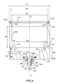
- the figure 1 shows a cross-sectional view of a prototype of the molding device according to the invention.
- the molding device of the figure 1 essentially comprises a molding assembly 10 and a bell 12 of transparent material containing the vacuum molding assembly.
- the molding device allows the collective production of 72 pyrotechnic relays in the form of cylinders of circular section from a polymerizable material comprising an explosive molecule.
- the figure 2 shows an exploded perspective view of the molding assembly of the molding device of the figure 1 .
- the longitudinal axis molding assembly 10 ' has an upper portion and a lower portion and, on the upper side thereof, a dispensing plate 30 of the polymerizable material in the molding assembly 10.
- the distribution 30 is of circular cylindrical shape, of axis of revolution AA ', having two main faces perpendicular to said axis AA', a stacking face 32 and a distribution face 34.
- the distribution plate 30 is integral, on the side of the stacking face 32, with a stacking shaft 40 of axis of revolution coinciding with the axis AA '
- the distribution plate 30 has a circular edge 42 of diameter D5, intended to be inserted into an opening of the bell 12 closing it tightly.
- the circular edge 42 of the distribution plate is connected to a clamping wall 46 in the form of a circular tube of diameter larger than the diameter D5 of the circular edge of the distribution plate 30 forming a shoulder 48 on the side of the inner surface of the wall. clamp 46 for positioning an injection tray 50 of the polymerizable material in the dispensing tray 30
- the clamping wall 46 of the distribution plate ends in a plane perpendicular to the axis AA 'by an edge 52 (see FIG. figure 2 ) having four horizontal clamping teeth 54 of the injection tray 50 in the tray of distribution 30, each in the form of crown portion, regularly distributed on the edge 52 of the distribution plate 30 about the axis AA ', each crown portion being included in a circular arc of 45 °.
- the plate P6 consists of three sub-plates S1, S2, S3 stacked together in rotation.
- the six molding plates each comprise a hole 60 in their axis of revolution for the passage of the stacking shaft 40 and a groove 62 in the thickness of the plate intended to make certain molding plates of the stack integral in rotation of the stacking shaft 40.
- Each of the six molding plates P1 to P6 comprises two parallel main faces, an upper main face Fs and a lower main face Fi, 12 cylindrical passages T1, T2, .. Tj,... T12, with axes of revolution VV ' between its upper main face and its lower main face, j being the rank of the cylindrical passage between 1 and 12 in each of the molding plates.
- the figure 3a shows a top view of a molding plate of the molding device of the figure 1 .
- the figure 3b an axial sectional view of the molding plate of the figure 3a .
- the cylindrical passages T1, T2, .. Tj, ... T12 are distributed regularly and identically on each of the molding trays, between 1 and 12 represents the rank of the passage.
- This architecture of the figure 1 is related to the existing industrial injection tool of the polymerizable material used for the validation of a prototype of the molding device as described.
- Other architectures could provide the main functions of the molding device according to the invention.
- the Figures 3a and 3b show in particular the molding plate P2.
- first passages T1, T2, T3, T4, T5, T6 are distributed in angular steps of 60 ° around the axis of the plate centered on a circle C1 of diameter d1
- six second passages T7, T8, T9, T10, T11, T12, offset by an angle ⁇ of 30 ° with respect to the first six passages are also distributed in angular pitch of 60 ° around the axis of the molding plate centered on a circle C2 of diameter d2 plus small than d1.
- the molding plates P1 to P6 are angularly positioned around the axis of revolution AA 'so that the axes VV' of the cylindrical passages Tj likewise rank j of the twelve molding trays are merged to be filled together and form a column Cj of polymerizable material of respective rank j passages, the height of the twelve molding trays.
- the stack of the six molding trays P1 to P6 is sandwiched between the distribution plate 30 and a vent plate 70 having two parallel main faces, a clamping face 72 of the stacking side and the other side of the vent plate, an outer face 74.
- the stacking shaft 40 has at its free end (see figure 1 ), on the side of the lower molding part 12, a threaded portion 80.
- the free end of the stacking shaft 40 is spherical, which allows, during one of the steps of the method of using the molding device described below, at the time of rotation of the vent plate 70 before injection of the polymerizable material, to have a point contact between this stacking shaft 40 and a central abutment integral with the bell 12 and thus to minimize the torque.
- a nut 82 screwed onto said threaded portion 80 maintains the stack of the molding trays P1, P2, P3, P4, P5, P6 clamped between the distribution plate 30 and the vent plate 70 so that the lower face Fi of a molding plate Pi of rank i is in contact with the upper face Fs of the following plate P (i + 1).
- the passages T1, T2, .. Tj,... T12 of the molding trays P1, P2, P3, P4, P5 provide the molding of the pyrotechnic relays of cylindrical shapes of circular section.
- the plate P6 ensures the realization of pyrotechnic relays with chamfers.
- the plate P6 consists of three sub-plates S1, S2, S3 made integral in rotation by pins (or any other device providing this function).
- the cylindrical passages T1, T2, .. Tj, ... T12 in the sub-plates S1 and S3 enclosing the sub-plate S2 are of inverted frustoconical shape representing the shape of the respective chamfers of the one and the other ends of the 12 relays molded in the molding plate P6 and the passages T1, T2, .. Tj, ... T12 in the subplates of molding S2 and S3, the circular cylindrical bodies of said 12 relays.
- the figure 3c shows a partial view in axial section of three passages Tj aligned row J in the three subplates S1, S2, S3 of the molding device of the figure 1 , and the half-rank pyrotechnic relay molded in these three passages.
- the pyrotechnic relays are obtained by sliding one mold plate on the other, in this embodiment by rotation around the stacking shaft 40, to perform a cutting each of the columns C1, C2, ... Cj,... C12 of polymerizable material injected into the aligned passages T1, T2, .. Tj,... T12 of the six molding plates.
- the stacking shaft 40 comprises three locking screws 84 in rotation of the molding plates screwed on the stacking shaft 40 perpendicular to the axis of revolution AA 'and positioned along the length of the stacking shaft 40 so that when the stack of the molding plates is formed, the heads of the three screws 84 are in the grooves of the respective plates P2, P4, P6, the grooves of the other plates P1, P3, P5 having no screw heads are then free to rotate on the stacking shaft 40.
- the tray 30 distribution channel comprises 12 injection channels I1, I2 ... Ij, .. I12 between its stack face 32 and its distribution face 34 distributed on its faces in the same way to that of the cylindrical passages T1, T2 ,. .Tj,... T12 of the molding trays so that, in the so-called injection position, an injection passage Ij of rank j is aligned with the passages Tj of the same rank in the six molding trays.
- the molding plates have on their circular edge angular positioning marks.
- the vent plate 70 makes it possible to maintain the polymerizable material in the passages of the molding plates during its injection into the molding assembly, but also, according to a main characteristic of the molding device according to the invention, suction of the air contained in said passages of the molding plates to put them under vacuum.
- the vent plate 70 thus comprises 12 vent holes E1, E2,... Ej,... E12 between its clamping face 72 and its outer face 74 distributed identically to that of the cylindrical passages T1, T2, ..Tj, ...
- the vent plate 70 comprises, on the side of its outer face 74, blind holes 76 for the insertion of driving pins 137 in rotation with the bell 12.
- the injection plate 50 ensures the arrival of the polymerizable material on the distribution face 34 of the distribution plate 30 and in the 12 injection channels I1, I2, ... Ij, .. I12 of the distribution plate 30 .
- the injection tray 50 of circular cylindrical shape has on the side of the upper part of the molding assembly 10 an inlet 92 of polymerizable material in the form of a circular section tube.
- the inner surface of the tube 94 widening in the thickness of the injection plate 50 in conical form to open on the distribution face 34 of the distribution plate 30 in the form of a circular opening having a diameter encompassing all 12 injection channels I1, I2, ... Ij, .. I12 of the distribution plate 30.
- the injection plate 50 has at its periphery four clamping walls 100 distributed regularly about the axis AA 'each having a stop 102, said clamping walls 100 being able to be positioned under a respective horizontal clamping tooth 54 of the edge 52 of the distribution plate 30 for locking in translation and in rotation of the injection plate 50 with the distribution plate 30 integral with the stack of the molding plates.
- An O-ring 110 in a groove 112 on the periphery of the injection plate 50 seals with the external medium.
- the figure 4 shows a view in axial section of the bell of the molding device of the figure 1 .
- the bell 12 is intended to receive the molding assembly 10 and to hold said assembly under vacuum during an injection phase of the polymerizable material in the passages T1, T2, .. Tj, ... T12 of the trays molding P1, P2, P3, P4, P5, P6.
- the bell 12 of circular cylindrical shape of external diameter D1, of axis of revolution CC ' comprises, from one end to the other of the bell, a bell bottom 120 and a bell edge 122.
- a bottom wall 124 of bell-shaped shell H2 has a smooth hole 126 opening into the interior of the bell.
- the bell bottom wall 124 comprises, inside the bell 12, a circular flat surface 128 of diameter D2 widening in the form of an opening 130 of conical shape up to a diameter D3 over a height H3 to inside the bell.
- the conical opening 130 is connected to a circular cylindrical opening 134 of diameter D4 larger than the diameter D3 of the conical opening to form a plateau shoulder 135 on a height H4 having pin holes 136 for the insertion of pins.
- the circular cylindrical opening 134 is connected by another shoulder 138 to a last opening 139 of the bell diameter D5 greater than the diameter D4 of the circular cylindrical opening 134 and less than the outer diameter D1 of the bell to form a wall 140 of bell edge ending in the bell edge 122.
- the wall 140 of edge of bell has a groove 141 opening into the interior of the bell 12 containing a seal 142 intended to be in contact with the circular edge 42 of the distribution plate to seal against the external medium between the molding assembly 10 and the bell 12
- the plating force of the bell 12 on the molding assembly 10, and therefore on the molding plates, due to the vacuum in the bell, can be adapted by choosing the diameter D5 of the bell, which, depending on the material injected , can ensure better inter tray sealing.
- the minimum diameter D5 of the bell must be compatible with the minimum value of the diameter of the trays, the maximum diameter D5 can be chosen all the greater that it is desired to obtain a greater plating force.
- a bell bottom insert 143 comprising a flat head 144 and a cylindrical body 146 having in the axis CC 'of revolution a tapped hole 148 opening into the interior of the bell 12.
- the insert 143 of the bell bottom is maintained in the smooth hole 126 of the bell bottom 120 with the nut 149 so that a lower surface of the head of the bell bottom insert 143 abuts with the circular flat surface 128 of the bottom wall 124 of the bell Bell.
- the bell bottom insert 143 has a central abutment 150 screwed into the threaded hole 148 of the bell bottom insert 143.
- the central stop 150 can be brought into contact, inside the bell 12, with the free end of the stacking shaft 40 to enable the relay to be changed during the relay production cycle. bell on the injection tool in order to limit or on the contrary increase according to the operation of the cycle carried out, the effort of plating trays between them.
- a bell bottom seal 160 between the bell bottom insert 142 and the bell bottom wall 124 provides, at the bottom of the bell, the seal of the bell 12 relative to the ambient medium.
- the bell comprises, for producing the vacuum in the molding device, a vent 170 of axis YY 'in the thickness H3 of the conical opening 130.
- the figure 5 shows an exploded perspective view of the bell 12 of the figure 4 showing the bell bottom insert 143 and the central stop 150.
- the shapes of the pyrotechnic relays produced by the molding device according to the invention are those of cavities Av formed by the volume between the walls of the cylindrical passages T1, T2,... Tj,... T12 in the molding trays. closed by the lower and upper surfaces of adjacent molding trays after rotation of the molding trays relative to one another.
- the shapes of the pyrotechnic relays are not limiting to those of the production of the molding trays of the Figures 3b and 3c and other more complex shapes can be made by superposition of several sub-plates integral in rotation.
- the shapes of the relays can be obtained by the addition of two half-shells in each cell. The two half-shells then form a passage thus making it possible to inject molded elements of all shapes, for example in the form of a diabolo which will be easily demoldable.
- the shapes of the relays can be obtained by circular cylindrical capsules inserted into the passages of the molding plates. Passages in the capsules make it possible to obtain other forms of relay.
- the molding plates of the molding device can combine all these variants to obtain with the molding device according to the invention different forms of relay in a single molding.
- FIGS. 6a and 6b show two embodiments of elements molded by the molding device of the figure 1 .
- figure 6a shows a molded element m1 by three sub plates Sx, S (x + 1), S (x + 2) integral in rotation during molding forming a single molding plate having a chamfer 45 ° side of the sub-plate Sx and a reduction of the diameter of the sub-plateau S (x + 2), the subset S (x + 1) forming the circular cylindrical body of the relay m1.
- the figure 6b shows the realization of a molded element m2 in the form of a barrel.
- the barrel shape is obtained by combining two subplates Sx and S (x + 1) having concave cylindrical shaped passages assembled on the side of their larger diameter.
- the sections of the passages in the trays or in the sub-trays may also be of any shape, for example of square section, triangular or other.
- the figure 7a shows an axial sectional view of a variant of the molding plate of the figure 3a .
- the molding plate P2 for example, comprises in each passage T1, T2, .. Tj, ... T12, two half-shells 300, 302 of relay having a cylindrical passage of diameter D10 in a central part of the half shells and widening to the diameter D12, larger than the diameter D10, to the lower surface Fi and upper Fs of the molding plate.
- the half-shells 300, 302 have a circular cylindrical edge of diameter D14 larger than the diameter D12 of the two half-shells being inserted into a recess 304 on the side of the upper surface Fs of the molding plate so as to block in position of the two half-shells in the passage of the molding plate.
- the figure 7b shows a top view of a half-shell of the plateau of the figure 7a .
- the Figure 7c an axial view of the molded relay from the molding plate of the figure 7a .
- the figure 7d shows another relay resulting from a molding of a tray comprising three sub-trays, the molding plate of the figure 7a comprising the two half-shells 300, 302 of molding sandwiched between two other sub-trays to form a chamfer 306 of a coast of the relay of the Figure 7c and a D16 diameter reduction on the other side of the relay.
- the two half-shells 301, 302 of the molding plate of the figure 7a have edges 320, 322 in contact over the entire height of the half-shells in a plane of symmetry Ps.
- edges 320, 322 of two half-shells 340, 342 are in contact only on one or more parts of the thickness of the plate, or of a sub-molding plate, to form one or more respective passages of polymerizable material to the surface of the passage Tj in the molding plate.
- edges 320, 322 of the two half-shells are inclined at least on a part of the thickness of the tray or the sub-plate of the molding relative to the plane of symmetry Ps of the half-shells.
- the figure 7e shows an exemplary embodiment of two half-shells of the molding plate of the figure 7a having one side with a passage 320 with parallel edges and the other side inclined edges 322.
- figure 7e shows a molding plate of a pyrotechnic relay 350 (or of a generally molded element) made from four sub-mold plates S1, S2, S3, S4, (represented in dashed line on the figure 7e )
- the mold sub-tray S1 forms a diameter reduction D20 of the relay 350
- the sub-plates S2 and S4 form chamfers of the relay
- the central sub-plate S3 having the two half-shells 340, 342 forms the body of the relay 350.
- the figure 7f shows a section of the pyrotechnic relay 350 resulting from the molding of the two half-shells 340, 342 of the figure 7e comprising, on one side, a protrusion 360 of rectangular section and on the other side another protrusion 362 of triangular section.
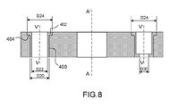
- the figure 8 shows a view in axial section of another variant of the molding plate of the figure 3a .
- the plate P2 for example, comprises in each passage T1, T2, .. Tj, ... T12 of circular cylindrical shape a molding capsule 400 in the form of a tube of external diameter D20 and internal diameter D22 having an edge 402 of larger diameter D24 than the external diameter D20 inserted in a recess 404 on the side of the upper surface Fs of the molding plate so as to immobilize in position the molding capsule 400 in the passage Tj of the molding plate .
- the molding capsule 400 may comprise a ring 420 of the side of one of its ends to form a diameter reduction D30 of the relay molded by this capsule.
- the molding device is not limited to molding trays that can slide relative to each other by rotation around the stack axis AA 'for the production of the molded elements, other types of movement may be envisaged, for example by sliding in translation from one plate to the other.
- the molding plates are for example guided by straight rails to slide on their main faces with respect to each other and thus create the cells containing the polymerizable material.
- the main surfaces of the molding trays P1, P2, P3, P4, P5, P6 as well as the passages T1, T2, .. Tj,... T12 in the molding and distribution trays 30 can be covered with a thin teflon layer or other product of equivalent function of one or two tenths of a mm, so as to facilitate the sliding of a molding plate relative to the other and the demolding of the molded elements.
- the invention also relates to a molding process by the implementation of the molding device according to the invention.
- FIG. figure 1 The Figures 9a, 9b, 9c and 9d represent, in the form of schematic diagrams, the main stages of implementation of the molding device according to the invention shown in FIG. figure 1 .
- An industrial tool for injecting polymerizable material 200 in the molding device according to the invention comprises an access 202 intended to be connected to the entry 92 of polymerizable material of the molding assembly 10.
- the access 202 of the industrial injection tool is isolated from the environment to be able to perform the vacuum in the bell of the molding device.
- the polymerization can be accelerated by setting oven and temperature rise of the molding assembly.
- the rotation of the free molding trays after the injection of polymerizable material takes place at a predetermined angle using a mark of rotation on each edge of the molding plates so that the cells Av are closed by the rotation of molding trays.
- the bell 12 is made of transparent plastic material to monitor any leakage of material in the molding assembly.
- the device and the method according to the invention make it possible to mass produce small priming relays free of air bubbles and cracks.
- This priming relay meets the standards of muratisation (MURAT standards) and complies with the standardization files in force.
- the invention is not limited to the production of pyrotechnic priming relays, other non-explosive elements of polymerizable material can be made by the use of the molding device according to the invention.
- the architecture of the molding device according to the invention described is that of a prototype feasibility and therefore the simplest possible adaptable to the industrial tool in place, knowingly neglecting certain details that would improve considerably the industrial aspect of the molding device but at this stage of the study were not dimensioning, for example, the rotation of the trays relative to each other is in this prototype of feasibility made manually after extracting the bell empty.
- the rotation of these trays would be automated remotely and could be performed without removing the bell.
Landscapes
- Engineering & Computer Science (AREA)
- Mechanical Engineering (AREA)
- Manufacturing & Machinery (AREA)
- Moulds For Moulding Plastics Or The Like (AREA)
- Injection Moulding Of Plastics Or The Like (AREA)
Abstract
Description
L'invention concerne un outillage industriel destiné à la réalisation par moulage d'éléments en matière polymérisable et en particulier des relais d'amorçage pyrotechniques.The invention relates to an industrial tool for producing by molding elements of polymerizable material and in particular pyrotechnic priming relays.
Le moulage de petites pièces notamment en matière plastique ou en matière polymérisable fait appel à différentes techniques et outillages de moulage. Une technique fréquemment utilisée pour des réalisations mono-injection en série est le moulage par injection. Les moules sont constitués le plus souvent de deux coquilles comportant une partie fixe et une partie mobile pressées l'une contre l'autre au moment du moulage. La matière sous forme pâteuse ou liquide est alors injectée à chaud ou à froid dans le moule sous forte pression. Lorsque la matière est solidifiée, par exemple lors de son refroidissement ou d'une polymérisation, les coquilles sont écartées pour extraire la pièce du moule.The molding of small parts including plastic or polymerizable material uses different molding techniques and tools. A technique frequently used for single-injected series production is injection molding. The molds are usually constituted of two shells having a fixed portion and a movable portion pressed against each other at the time of molding. The material in pasty or liquid form is then injected hot or cold into the mold under high pressure. When the material is solidified, for example during its cooling or polymerization, the shells are spread apart to extract the piece from the mold.
Une autre méthode de moulage, cette fois en collectif (ou multi injection par opposition au précédent procédé), permet de mouler plusieurs pièces simultanément par un dispositif de moulage comportant plusieurs alvéoles de moulage ayant la forme des pièces à mouler reliées par des canaux conduisant la matière sous forme pâteuse dans chaque alvéole. Cette autre méthode en collectif nécessite la réalisation d'un dispositif complexe et coûteux pour injecter la matière sous pression afin de bien remplir les alvéoles.Another method of molding, this time collectively (or multi injection as opposed to the previous method), allows to mold several parts simultaneously by a molding device having a plurality of molding cavities having the shape of moldings connected by channels leading the material in pasty form in each cell. This other method in collective requires the realization of a complex and expensive device for injecting the material under pressure to properly fill the cells.
Ces types de moulage par injection de matière sous pression comportent des inconvénients tels que des moulages non homogènes et parfois comportant des bulles d'air. En outre, les pièces extraites de ce type de moule en collectif peuvent comporter des petites excroissances dues au canal d'arrivée de la matière dans le moule qu'il faudra par la suite usiner pour obtenir la pièce moulée définitive.These types of injection molding of pressurized material have disadvantages such as non-homogeneous moldings and sometimes with air bubbles. In addition, the parts extracted from this type of collective mold may have small growths due to the arrival channel of the material in the mold that will subsequently be machined to obtain the final molded part.
Lorsqu'il s'agit de moulage de matière explosive destinée aux armements tels que les relais pyrotechniques, l'usinage final présente un risque d'inflammation des relais par les frottements ou l'arrachage de matière. Une procédure d'usinage à distance doit être mise en place ce qui augmente encore le coût de fabrication.When it comes to explosive material molding intended for armaments such as pyrotechnic relays, the final machining presents a risk of ignition relays by friction or tearing material. A remote machining procedure must be implemented which further increases the manufacturing cost.
Pour palier les inconvénients des dispositifs ou outillages de moulage de l'état de l'art, l'invention propose un dispositif de moulage en collectif d'éléments en matière polymérisable,To overcome the drawbacks of molding devices or tools of the state of the art, the invention proposes a device for collective molding of elements made of polymerizable material,
Le dispositif de moulage comporte un ensemble de moulage et une cloche destinée à maintenir l'ensemble de moulage sous vide, l'ensemble de moulage ayant un empilage de n plateaux de moulage P1, P2,...Pi,...Pn, selon un axe d'empilement AA', chacun des plateaux de moulage ayant, deux faces principales parallèles, une face principale supérieure et une face principale inférieure, k passages T1, T2,..Tj,...Tk entre sa face principale supérieure et sa face principale inférieure, j étant le rang du passage compris entre 1 et k, les plateaux de moulage pouvant glisser les uns par rapport aux autres dans les plans des faces principales pour être mis, soit dans une position dite d'injection sous vide, dans laquelle les passages T1, T2,..Tj,...Tk sous vide de même rang j des n plateaux de moulage P1, P2,...Pi,...Pn sont alignés pour former k conduits Cd1, Cd2, ...Cdj,...Cdk destinés à être remplis ensemble par la matière polymérisable, soit dans une position dite de fermeture telle que les k dits passages T1, T2,..Tj,...Tk d'un plateau Pi de rang i considéré contenant la matière polymérisable soient fermés d'un côté par la face inférieure du plateau de moulage P(i-1) précèdent et de l'autre côté par la face supérieure du plateau de moulage suivant P(i+1) de l'empilement formant des cavités de la forme des passages contenant la matière polymérisable, l'empilement des n plateaux de moulage étant enserré entre un plateau de distribution de la matière polymérisable dans les passages T1, T2,..Tj,...Tk sous vide et un plateau d'évent pour faciliter l'obtention du vide dans les dits passages et la fermeture, du côte du plateau d'évent, des k conduits Cd1, Cd2, ...Cdj,...Cdk avant l'injection de la matière polymérisable.The molding device comprises a molding assembly and a bell for holding the vacuum molding assembly, the molding assembly having a stack of n molding trays P1, P2, ... Pi, ... Pn, along a stacking axis AA ', each of the molding plates having, two parallel main faces, an upper main face and a lower main face, k passages T1, T2, .. Tj, ... Tk between its upper main face and its lower main face, j being the rank of the passage between 1 and k, the molding trays being able to slide relative to each other in the planes of the main faces to be put, either in a so-called vacuum injection position , in which the passages T1, T2, .. Tj,... Tk under vacuum of the same rank j n molding plates P1, P2, ... Pi, ... Pn are aligned to form k ducts Cd1, Cd2 , ... Cdj, ... Cdk intended to be filled together by the polymerizable material, either in a so-called closing position such the said k-passages T1, T2, .. Tj, ... Tk of a plateau Pi of rank i considered containing the polymerizable material are closed on one side by the underside of the molding plate P (i-1 ) before and on the other side by the upper face of the molding plate according to P (i + 1) of the stack forming cavities of the form of the passages containing the polymerizable material, the stack of n molding trays being enclosed between a distribution plate of the polymerizable material in the passages T1, T2, .. Tj, ... Tk under vacuum and a vent plate to facilitate obtaining the vacuum in said passages and closure, the coast of vent plate, k ducts Cd1, Cd2, ... Cdj, ... Cdk before the injection of the polymerizable material.
Dans une réalisation du dispositif de moulage, le plateau d'évent comporte k trous d'évent E1, E2,..Ej,...Ek tels que, dans une position dite de réalisation du vide dans l'ensemble de moulage, les k trous d'évent sont alignés avec les k passages T1, T2,..Tj,...Tk des n plateaux de moulage P1, P2,...Pi,...Pn, de façon à faciliter l'établissement du vide dans les passages des n plateaux de moulage avant l'injection de la matière polymérisable..In one embodiment of the molding device, the vent plate comprises k vent holes E1, E2,... Ej,... Ek such that, in a so-called vacuum-forming position in the molding assembly, the k vent holes are aligned with k passages T1, T2, .. Tj, ... Tk n molding plates P1, P2, ... Pi, ... Pn, so as to facilitate the establishment of the vacuum in the passages of n molding trays before the injection of the polymerizable material.
Dans une autre réalisation, le plateau de distribution comporte k canaux d'injections I1, I2 ,...Ij,.. Ik répartis de façon que, dans la position dite d'injection sous vide, les k trous d'injection sont alignés avec les k passages des n plateaux de moulage P1, P2,... Pi,... Pn, de façon à injecter sous vide la matière polymérisable dans les dits k passages.In another embodiment, the distribution plate comprises k injection channels I1, I2, ... Ij, .. Ik distributed so that, in the so-called vacuum injection position, the k injection holes are aligned. with the k passes of n molding trays P1, P2, ... Pi, ... Pn, so as to inject under vacuum the polymerizable material in said k passages.
Dans une autre réalisation, au moins un plateau de moulage Pi de l'empilement des n plateaux de moulage est constitué de w sous plateaux S1, S2,.. St,...Sw, w étant égal ou supérieur à 2, les w sous plateaux étant empilés et rendus solidaires pour former les passages T1, T2,..Tj,...Tk du plateau de moulage Pi.In another embodiment, at least one molding plate Pi of the stack of n molding trays consists of w under trays S1, S2, .. St, ... Sw, w being equal to or greater than 2, the w under trays being stacked and made integral to form the passages T1, T2, .. Tj, ... Tk of the molding plate Pi.
Dans une autre réalisation, les passages T1, T2,..Tj,...Tk, sont de forme choisie parmi les formes, concaves, convexes, tronconiques ou autres formes diverses.In another embodiment, the passages T1, T2, .. Tj,... Tk, are of a shape chosen from the forms, concave, convex, frustoconical or other various forms.
Dans une autre réalisation, les passages T1, T2,..Tj,...Tk, sont de forme cylindrique d'axe de révolution VV'.In another embodiment, the passages T1, T2, .. Tj,... Tk, are of cylindrical shape with an axis of revolution VV '.
Dans une autre réalisation, le sous plateau de premier rang S1 et le sous plateau de dernier rang Sw ont des passages T1, T2,..Tj,...Tk, de forme tronconique pour former des chanfreins sur les éléments moulés.In another embodiment, the sub-platter of first rank S1 and the sub-platter of last rank Sw have passages T1, T2, .. Tj, ... Tk, of frustoconical shape to form chamfers on the molded elements.
Dans une autre réalisation, au moins un plateau de moulage, comporte dans au moins un passage T1, T2,..Tj,...T12, deux demi-coquilles de moulage d'un élément en matière polymérisable de part et d'autre d'un plan passant par l'axe de révolution VV' du passage.In another embodiment, at least one molding plate, comprises in at least one passage T1, T2, .. Tj, ... T12, two half-shells for molding an element of polymerizable material on either side a plane passing through the axis of revolution VV 'of the passage.
Dans une autre réalisation, les deux demi- coquilles comportent au moins deux bords partiellement en contact pour réaliser un passage entre les deux demi-coquilles pour la matière polymérisable, les dits passages étant configurés pour former des excroissances dans le corps de l'élément moulé ayant une section, dans un plan perpendiculaire au passage, de forme prédéterminée choisie parmi les formes semi sphérique, tronconique, rectangulaire, triangulaire ou autres formes souhaitées.In another embodiment, the two half-shells comprise at least two edges partially in contact to make a passage between the two half-shells for the polymerizable material, said passages being configured to form protrusions in the body of the molded member having a section, in a plane perpendicular to the passageway, of predetermined shape selected from semi-spherical, frustoconical, rectangular, triangular or other desired shapes.
Dans une autre réalisation, au moins un plateau de moulage, comporte dans au moins un passage T1, T2,..Tj,...T12, une capsule de moulage.In another embodiment, at least one molding plate, comprises in at least one passage T1, T2, .. Tj, ... T12, a molding capsule.
Dans une autre réalisation, les n plateaux de moulage sont de forme cylindrique circulaire, chacun des n plateaux de moulage comportant un trou dans l'axe d'empilement AA' pour le passage d'un arbre d'empilage (40) solidaire, par une de ses deux extrémités, du plateau de distribution (30), un plateau de moulage Pi de rang i étant solidaire en rotation de l'arbre d'empilage, le plateau de moulage précédent P(i-1) ou suivant P(i+1) est libre en rotation par rapport audit arbre d'empilage de façon à produire un glissement d'un plateau de moulage par rapport au suivant et au précédent vers la position dite de fermeture.In another embodiment, the n molding plates are of circular cylindrical shape, each of the n molding plates having a hole in the stack axis AA 'for the passage of a stacking shaft (40) secured by one of its two ends, the distribution plate (30), a molding plate Pi of rank i being integral in rotation with the stacking shaft, the preceding molding plate P (i-1) or following P (i +1) is free to rotate relative to said stacking shaft so as to produce a sliding of a molding plate relative to the next and previous to the so-called closing position.
Dans une autre réalisation, les n plateaux de moulage sont de forme rectangulaire chacun des plateaux de moulage étant guidé longitudinalement dans un plan parallèle à ses faces principales de façon à produire un glissement d'un plateau par rapport au suivant et au précédent vers la position dite de fermeture.In another embodiment, the n molding plates are of rectangular shape each of the molding plates being guided longitudinally in a plane parallel to its main faces so as to produce a sliding of a plate with respect to the next and the previous towards the position said closing.
Dans une autre réalisation, la cloche est de forme cylindrique circulaire de diamètre externe D1, d'axe de révolution CC', comportant, d'une extrémité à l'autre de la cloche, un fond de cloche et un bord de cloche, du côté du fond de cloche une paroi de fond de cloche d'épaisseur H2 comportant un trou lisse débouchant à l'intérieur de la cloche, la paroi de fond de cloche comportant, à l'intérieur de la cloche une surface plane circulaire de diamètre D2 s'élargissant sous forme d'une ouverture de forme conique jusqu'à un diamètre D3 sur une hauteur H3 à l'intérieur de la cloche, l'ouverture conique étant raccordée à une ouverture cylindrique circulaire de diamètre D4 plus grand que le diamètre D3 de l'ouverture conique pour former un épaulement de plateau sur une hauteur H4 comportant des trous de goupilles pour l'insertion de goupilles d'entraînement en rotation du plateau d'évent de l'ensemble de moulage, l'ouverture cylindrique circulaire étant raccordée par un autre épaulement à une dernière ouverture de la cloche de diamètre D5 supérieure au diamètre D4 de l'ouverture cylindrique circulaire et inférieure au diamètre externe D1 de la cloche pour former une paroi de bord de cloche se terminant par le bord de cloche .In another embodiment, the bell is of circular cylindrical shape of external diameter D1, of axis of revolution CC ', comprising, from one end to the other of the bell, a bell bottom and a bell edge, of side of the bell bottom a bell bottom wall of thickness H2 having a smooth hole opening into the interior of the bell, the bell bottom wall comprising, inside the bell a flat circular surface of diameter D2 widening in the form of a conically shaped opening to a diameter D3 on a height H3 inside the bell, the conical opening being connected to a circular cylindrical opening of diameter D4 greater than the diameter D3 of the conical opening for forming a tray shoulder on a height H4 having pin holes for insertion of rotary drive pins of the vent plate of the molding assembly, the circular cylindrical opening being connected by another shoulder to a last opening of the bell diameter D5 greater than the diameter D4 of the circular cylindrical opening and less than the outer diameter D1 of the bell to form a bell edge wall ending in the bell edge.
Dans une autre réalisation, la paroi de bord de cloche comporte une gorge débouchant à l'intérieur de la cloche contenant un joint de plateau en contact avec un bord circulaire du plateau de distribution pour réaliser l'étanchéité par rapport au milieu externe entre l'ensemble de moulage et la cloche.In another embodiment, the bell edge wall has a groove opening inside the bell containing a plate seal in contact with a circular edge of the distribution plate for sealing against the external medium between the set of molding and the bell.
Dans une autre réalisation, un insert de fond de cloche comportant une tête plate et un corps cylindrique ayant dans l'axe CC' de révolution un trou taraudé débouchant à l'intérieur de la cloche, l'insert de fond de cloche étant maintenu par un écrou dans le trou lisse du fond de cloche de façon qu'une surface inférieure de la tête de l'insert de fond de cloche vienne en butée avec la surface plane circulaire de la paroi de fond de cloche.In another embodiment, a bell bottom insert having a flat head and a cylindrical body having in the axis CC 'of revolution a tapped hole opening into the interior of the bell, the bottom insert of the bell being maintained by a nut in the smooth hole of the bell bottom so that a lower surface of the head of the bell bottom insert abuts with the circular flat surface of the bell bottom wall.
Dans une autre réalisation, l'insert de fond de cloche comporte une butée centrale vissée dans le trou taraudé de l'insert de fond de cloche, le vissage ou le dévissage de la butée centrale dans l'insert de fond de cloche permettant de faire évoluer au cours du cycle de réalisation des éléments moulés, l'appui de la cloche sur l'ensemble de moulage afin de limiter ou au contraire augmenter selon l'opération du cycle effectuée, l'effort de placage des plateaux entre eux.In another embodiment, the bell bottom insert comprises a central stop screwed into the threaded hole of the bell bottom insert, screwing or unscrewing of the central stop in the bell bottom insert allowing evolve during the production cycle of the molded elements, the support of the bell on the molding assembly to limit or on the contrary increase according to the operation of the cycle carried out, the plating force of the plates between them.
Dans une autre réalisation, les faces principales des n plateaux de moulage P1, P2,...Pi,...Pn, ainsi que les k passages cylindriques T1, T2,..Tj,...Tk, sont recouverts d'un revêtement anti friction de un ou deux dixièmes de mm, de façon à faciliter le glissement d'un plateau de moulage par rapport à l'autre et le démoulage des éléments moulés.In another embodiment, the main faces of the n molding plates P1, P2,... P1,... Pn, as well as the k cylindrical passages T1, T2,... Tj,... Tk, are covered with an anti-friction coating of one or two tenths of a mm, so as to facilitate the sliding of a molding plate relative to the other and the demolding of the molded elements.
Dans une autre réalisation, l'élément moulé est un relais d'amorçage pyrotechnique, la matière polymérisable étant une molécule explosive enrobée d'un liant.In another embodiment, the molded element is a pyrotechnic priming relay, the polymerizable material being an explosive molecule coated with a binder.
L'invention concerne aussi un procédé de moulage mettant en oeuvre un dispositif de moulage en collectif d'éléments en matière polymérisable selon l'invention,
caractérisé en ce qu'il comporte au moins les étapes suivantes :
- montage de l'ensemble de moulage par l'empilement des n plateaux de moulage P1, P2, ... Pi, ... Pn enserrés entre le plateau de distribution de matière polymérisable et le plateau d'évent,
- alignement des k passages T1, T2, ..Tj,...Tk, des n plateaux de moulage P1, P2,... Pi,... Pn, les passages Tj de même rang j des n plateaux de moulage étant alignes pour former k conduits Cd1, Cd2, ...Cdj,...Cdk dans les n plateaux de moulage de la matière polymérisable,
- mise en place de la cloche sur l'ensemble de moulage isolant ainsi les plateaux de moulage du milieu extérieur à la cloche,
- réalisation du vide dans la cloche et dans les passages T1, T2,..Tj,...Tk des n plateaux de moulage par aspiration d'air dans la cloche,
- fermeture des conduits Cd1, Cd2, ...Cdj,...Cdk du côté du plateau d'évent par un glissement du plateau d'évent par rapport à l'empilement des n plateaux de moulage P1, P2,...Pi,...Pn,
- injection par le plateau de distribution de la matière polymérisable dans les k conduits Cd1, Cd2, ...Cdj,...Cdk pour former k colonnes respectives C1, C2,...Cj,...Ck de matière polymérisable,
- déplacement des plateaux de moulage les uns par rapport aux autres par glissement sur leurs surfaces principales en contact de façon à sectionner les k colonnes respectives C1, C2,...Cj,...Ck de matière polymérisable formant des cavités Av contenant les éléments moulés en matière polymérisable,
- suppression du vide dans la cloche,
- retrait de la cloche de l'ensemble de moulage,
- polymérisation des éléments dans les cavités formées par les passages cylindriques fermés par les surfaces principales des plateaux de moulage,
- séparation des plateaux de moulage et démoulage des éléments moulés dans les cavités par leur retrait des passages cylindriques des plateaux de moulage.
characterized in that it comprises at least the following steps:
- mounting the molding assembly by stacking n molding trays P1, P2, ... Pi, ... Pn sandwiched between the polymerizable material distribution tray and the vent tray,
- alignment of k passages T1, T2, ..Tj, ... Tk, n molding plates P1, P2, ... Pi, ... Pn, the passages Tj of the same rank j n molding plates being aligned to form k ducts Cd1, Cd2, ... Cdj, ... Cdk in the n molding trays of the polymerizable material,
- placing the bell on the insulating molding assembly and the molding trays from the outside environment to the bell,
- realization of the vacuum in the bell and in the passages T1, T2, .. Tj, ... Tk n trays of air suction molding in the bell,
- closing the ducts Cd1, Cd2, ... Cdj, ... Cdk on the side of the vent plate by a sliding of the vent plate relative to the stack of n molding plates P1, P2, ... Pi ... Pn,
- injection by the distribution plate of the polymerizable material in k conduits Cd1, Cd2, ... Cdj, ... Cdk to form k respective columns C1, C2, ... Cj, ... Ck polymerizable material,
- moving the molding plates relative to each other by sliding on their main surfaces in contact so as to cut the respective k columns C1, C2, ... Cj, ... Ck of polymerizable material forming cavities Av containing the elements molded of polymerizable material,
- removal of the void in the bell,
- removal of the bell from the molding assembly,
- polymerization of the elements in the cavities formed by the cylindrical passages closed by the main surfaces of the molding plates,
- separating the molding plates and demolding the molded elements in the cavities by removing them from the cylindrical passages of the molding plates.
Dans une réalisation du procédé de moulage, les n plateaux de moulage étant de forme cylindrique circulaire chacun des n plateaux comportant un trou dans l'axe d'empilement AA' pour le passage d'un arbre d'empilage, solidaire par une de ses deux extrémités, du plateau de distribution, un plateau de moulage de rang Pi étant solidaire en rotation de l'arbre d'empilage, le plateau de moulage précédent P(i-1) ou suivant P(i+1) étant libre en rotation par rapport audit arbre,
caractérisé en ce que la position de fermeture est obtenue par rotation d'un plateau de moulage Pi par rapport au suivant P(i+1) et au précédent P(i-1).In one embodiment of the molding process, the n molding plates being of circular cylindrical shape each of n trays having a hole in the stacking axis AA 'for the passage of a stacking shaft, secured by one of its two ends of the distribution plate, a molding plate of rank Pi being integral in rotation with the stacking shaft, the preceding molding plate P (i-1) or following P (i + 1) being free in rotation with respect to said tree,
characterized in that the closing position is obtained by rotation of a molding plate Pi with respect to the following P (i + 1) and the previous P (i-1).
Dans une autre réalisation du procédé de moulage, les n plateaux de moulage étant de forme rectangulaire et guidés longitudinalement dans un plan parallèle à ses faces principales,
caractérisé en ce que la position de fermeture est obtenue par le glissement d'un plateau de moulage Pi par rapport au suivant P(i+1) et au précédent P(i-1).In another embodiment of the molding process, the n molding plates being of rectangular shape and guided longitudinally in a plane parallel to its main faces,
characterized in that the closed position is obtained by sliding a molding plate Pi with respect to the following P (i + 1) and the previous P (i-1).
L'idée de cette invention est d'injecter sous vide de la matière polymérisable dans des passages de plateaux de moulage indexés puis de faire glisser ces plateaux de moulage les uns par rapport aux autres pour obtenir une multitude de cavités comportant les éléments moulés.The idea of this invention is to vacuum-inject the polymerizable material into indexed mold tray trays and then slide these mold trays relative to one another to provide a multitude of cavities with the molded elements.
Un principal but de ce dispositif est d'obtenir un moulage en grande série d'éléments moulés de formes géométriques quelconques sans retouche ultérieure.A main purpose of this device is to obtain a mass molding of molded elements of any geometric shapes without subsequent retouching.
Un autre objectif est de réduire le coût de fabrication des éléments moulés tels que des relais d'amorçage pyrotechniques.Another objective is to reduce the manufacturing cost of the molded elements such as pyrotechnic priming relays.
L'invention sera mieux comprise par la description de réalisations d'un dispositif de moulage et du procédé de mise en oeuvre du dispositif selon l'invention en référence aux dessins indexés dans lesquels :
- la
figure 1 montre une vue en coupe transversale d'un prototype du dispositif de moulage selon l'invention ; - la
figure 2 montre une vue éclatée en perspective de l'ensemble de moulage du dispositif de moulage de lafigure 1 ; - la
figure 3a montre une vue de dessus d'un plateau de moulage du dispositif de moulage de lafigure 1 ; - la
figure 3b une vue en coupe axiale du plateau de moulage de lafigure 3a ; - la
figure 3c montre une vue partielle en coupe axiale des passages alignés de rang j dans les trois sous plateaux S1, S2, S3 du dispositif de moulage de lafigure 1 ; - la
figure 4 montre une vue en coupe axiale de la cloche du dispositif de moulage de lafigure 1 ; - la
figure 5 montre une vue éclatée en perspective de la cloche 12 de lafigure 4 - les
figures 6a et 6b montrent deux exemples de réalisations d'éléments moulés par le dispositif de moulage desfigures 1 et 2 ; - la
figure 7a montre une vue en coupe axiale d'une variante du plateau de moulage de lafigure 3a ; - la
figure 7b montre une vue de dessus d'une demi-coquille du plateau de lafigure 7a ; - la
figure 7c une vue axiale du relais moulé issu du plateau de moulage de lafigure 7a ; - la
figure 7d montre un autre relais issu d'un moulage d'un plateau comportant trois sous plateaux ; - la
figure 7e montre un exemple de réalisation de deux demi-coquilles du plateau de lafigure 7a ; - la
figure 7f montre une section du relais pyrotechnique résultant du moulage des deux coquilles de lafigure 7 e ; - la
figure 8 montre une vue en coupe axiale d'une autre variante du plateau de moulage de lafigure 3a et ; - les
figures 9a, 9b, 9c et 9d représentent, sous forme de schémas de principe, des principales étapes de mise en oeuvre du dispositif de moulage selon l'invention représenté auxfigures 1 et 2 .
- the
figure 1 shows a cross-sectional view of a prototype of the molding device according to the invention; - the
figure 2 shows an exploded perspective view of the molding assembly of the molding device of thefigure 1 ; - the
figure 3a shows a top view of a molding plate of the molding device of thefigure 1 ; - the
figure 3b an axial sectional view of the molding plate of thefigure 3a ; - the
figure 3c shows a partial view in axial section of the rows of aligned passages j in the three sub-plates S1, S2, S3 of the molding device of thefigure 1 ; - the
figure 4 shows a view in axial section of the bell of the molding device of thefigure 1 ; - the
figure 5 shows an exploded perspective view of thebell 12 of thefigure 4 - the
Figures 6a and 6b show two examples of embodiments of elements molded by the molding device offigures 1 and2 ; - the
figure 7a shows an axial sectional view of a variant of the molding plate of thefigure 3a ; - the
figure 7b shows a top view of a half-shell of the plateau of thefigure 7a ; - the
Figure 7c an axial view of the molded relay from the molding plate of thefigure 7a ; - the
figure 7d shows another relay resulting from a molding of a tray comprising three sub-trays; - the
figure 7e shows an example of realization of two half-shells of the plateau of thefigure 7a ; - the
figure 7f shows a section of the pyrotechnic relay resulting from the molding of the two shells of thefigure 7 e ; - the
figure 8 shows a view in axial section of another variant of the molding plate of thefigure 3a and; - the
Figures 9a, 9b, 9c and 9d represent, in the form of schematic diagrams, the main stages of implementation of the molding device according to the invention shown in FIGS.figures 1 and2 .
Les
La
Le dispositif de moulage de la
Dans l'exemple de réalisation représenté à la
La
L'ensemble de moulage 10 d'axe longitudinal AA' comporte, une partie supérieure et une partie inférieure et, du côte de sa partie supérieure, un plateau de distribution 30 de la matière polymérisable dans l'ensemble de moulage 10. Le plateau de distribution 30 est de forme cylindrique circulaire, d'axe de révolution AA', comportant deux faces principales perpendiculaires audit axe AA', une face d'empilage 32 et une face de distribution 34.The longitudinal axis molding assembly 10 'has an upper portion and a lower portion and, on the upper side thereof, a dispensing
Le plateau de distribution 30 est solidaire, du côte de la face d'empilage 32, d'un arbre d'empilage 40 d'axe de révolution confondu avec l'axe AA'The
Le plateau de distribution 30 comporte un bord circulaire 42 de diamètre D5, destiné à être insérée dans une ouverture de la cloche 12 la fermant hermétiquement. Le bord circulaire 42 du plateau de distribution est raccordé à une paroi de serrage 46 en forme de tube circulaire de diamètre plus grand que le diamètre D5 du bord circulaire du plateau de distribution 30 formant un épaulement 48 du côté de la surface intérieure de la paroi de serrage 46 pour le positionnement d'un plateau d'injection 50 de la matière polymérisable dans le plateau de distribution 30The
La paroi de serrage 46 du plateau de distribution se termine dans un plan perpendiculaire à l'axe AA' par un bord 52 (voir
Entre la partie supérieure et la partie inférieure de l'ensemble de moulage 10, sont empilés sur le plateau de distribution 30 autour de l'arbre d'empilage 40, 6 plateaux de moulage P1, P2, P3, P4, P5, P6 de formes cylindriques circulaires de diamètres Dp. Comme est décrit plus loin dans cette réalisation le plateau P6 est constitué de trois sous plateaux S1, S2, S3 empilés solidaires en rotation.Between the upper part and the lower part of the
Les six plateaux de moulage comportent chacun un trou 60 dans leur axe de révolution pour le passage de l'arbre d'empilage 40 et une rainure 62 dans l'épaisseur du plateau destinée à rendre certains plateaux de moulage de l'empilement solidaires en rotation de l'arbre d'empilage 40.The six molding plates each comprise a
Chacun des six plateaux de moulage P1 à P6 comporte deux faces principales parallèles, une face principale supérieure Fs et une face principale inférieure Fi, 12 passages cylindriques T1, T2,..Tj,...T12, d'axes de révolution VV', entre sa face principale supérieure et sa face principale inférieure, j étant le rang du passage cylindrique compris entre 1 et 12 dans chacun des plateaux de moulage.Each of the six molding plates P1 to P6 comprises two parallel main faces, an upper main face Fs and a lower main face Fi, 12 cylindrical passages T1, T2, .. Tj,... T12, with axes of revolution VV ' between its upper main face and its lower main face, j being the rank of the cylindrical passage between 1 and 12 in each of the molding plates.
La
La
Les passages cylindriques T1, T2,..Tj,...T12 sont distribués régulièrement et de façon identique sur chacun des plateaux de moulage, j compris entre 1 et 12 représente le rang du passage.The cylindrical passages T1, T2, .. Tj, ... T12 are distributed regularly and identically on each of the molding trays, between 1 and 12 represents the rank of the passage.
Cette architecture de la
Les
Dans cet exemple de réalisation six premiers passages T1, T2, T3, T4, T5, T6 sont distribués par pas angulaire de 60° autour de l'axe du plateau centrés sur un cercle C1 de diamètre d1, six deuxièmes passages T7, T8, T9, T10, T11, T12, décalés d'un angle θ de 30° par rapport aux six premiers passages sont aussi distribués par pas angulaire de 60° autour de l'axe du plateau de moulage centrés sur un cercle C2 de diamètre d2 plus petit que d1.In this embodiment, six first passages T1, T2, T3, T4, T5, T6 are distributed in angular steps of 60 ° around the axis of the plate centered on a circle C1 of diameter d1, six second passages T7, T8, T9, T10, T11, T12, offset by an angle θ of 30 ° with respect to the first six passages are also distributed in angular pitch of 60 ° around the axis of the molding plate centered on a circle C2 of diameter d2 plus small than d1.
Dans une position de l'ensemble de moulage 10 dite « position d'injection », les plateaux de moulage P1 à P6 sont positionnés angulairement autour de l'axe de révolution AA' de façon que les axes VV' des passages cylindriques Tj de même rang j des douze plateaux de moulage soient confondus pour être remplis ensemble et former une colonne Cj de matière polymérisable respective de rang j des passages, de la hauteur des douze plateaux de moulage.In a position of the
L'empilage des six plateaux de moulage P1 à P6 est pris en sandwich entre le plateau de distribution 30 et un plateau d'évent 70 comportant deux faces principales parallèles, une face de serrage 72 du côte de l'empilage et, de l'autre côte du plateau d'évent, une face externe 74.The stack of the six molding trays P1 to P6 is sandwiched between the
L'arbre d'empilage 40 comporte à son extrémité libre (voir
L'extrémité libre de l'arbre d'empilage 40 est sphérique ce qui permet, lors d'une des étapes du procédé d'utilisation du dispositif de moulage décrite plus loin, au moment de la rotation du plateau d'évent 70 avant injection de la matière polymérisable, d'avoir un contact ponctuel entre cet arbre d'empilage 40 et une butée centrale solidaire de la cloche 12 et donc de réduire au maximum le couple de rotation.The free end of the stacking
Un écrou 82 vissé sur ladite partie filetée 80 assure le maintient de l'empilage des plateaux de moulage P1, P2, P3, P4, P5, P6, serrés entre le plateau de distribution 30 et le plateau d'évent 70 de façon que la face inférieure Fi d'un plateau de moulage Pi de rang i soit en contact avec la face supérieure Fs du plateau suivant P(i+1).A
Dans cette réalisation particulière du dispositif de moulage selon l'invention, représenté à la
Le plateau P6 assure la réalisation de relais pyrotechniques avec chanfreins. A cet effet, le plateau P6 est constitué de trois sous plateaux S1, S2, S3 rendus solidaires en rotation par des goupilles (ou tout autre artifice assurant cette fonction). Les passages cylindriques T1, T2,..Tj,...T12 dans les sous plateaux S1 et S3 enserrant le sous plateau S2 sont de forme tronconique inversée représentant la forme des chanfreins respectifs de l'une et de l'autre extrémités des 12 relais moulés dans le plateau de moulage P6 et les passages T1, T2,..Tj,...T12 dans les sous plateaux de moulage S2 et S3, les corps cylindriques circulaires des dits 12 relais.The plate P6 ensures the realization of pyrotechnic relays with chamfers. For this purpose, the plate P6 consists of three sub-plates S1, S2, S3 made integral in rotation by pins (or any other device providing this function). The cylindrical passages T1, T2, .. Tj, ... T12 in the sub-plates S1 and S3 enclosing the sub-plate S2 are of inverted frustoconical shape representing the shape of the respective chamfers of the one and the other ends of the 12 relays molded in the molding plate P6 and the passages T1, T2, .. Tj, ... T12 in the subplates of molding S2 and S3, the circular cylindrical bodies of said 12 relays.
La
Le démoulage des relais pyrotechniques avec chanfrein pourra s'effectuer sans difficultés par la désolidarisation de ces trois sous plateaux S1, S2 et S3.Release of the pyrotechnic relays with chamfer can be performed without difficulty by the separation of these three subplates S1, S2 and S3.
Selon une principale caractéristique du procédé de réalisation des relais pyrotechniques, les relais pyrotechniques sont obtenus par le glissement d'un plateau de moulage sur l'autre, dans cette réalisation par rotation autour de l'arbre d'empilage 40, pour effectuer une découpe de chacune des colonnes C1, C2,...Cj,...C12 de matière polymérisable injectée dans les passages alignés T1, T2,..Tj,...T12 des six plateaux de moulage.According to a main characteristic of the process for producing the pyrotechnic relays, the pyrotechnic relays are obtained by sliding one mold plate on the other, in this embodiment by rotation around the stacking
A cet effet, dans la réalisation du dispositif de moulage représenté aux
Pour effectuer le remplissage de matière polymérisable des passages cylindriques T1, T2,..Tj,...T12 des plateaux de moulage, le plateau de distribution 30 comporte 12 canaux d'injections I1, I2 ... Ij,.. I12 entre sa face d'empilage 32 et sa face de distribution 34 distribués sur ses faces de manière identique à celle des passages cylindriques T1, T2,..Tj,...T12 des plateaux de moulage de façon que, dans la « position dite d'injection » un passage d'injection Ij de rang j soit aligné avec les passages Tj de même rang j dans les six plateaux de moulage. A cet effet, les plateaux de moulage comportent sur leur bord circulaire des repères de positionnement angulaire.For performing the filling of polymerizable material of the cylindrical passages T1, T2, .. Tj, ... T12 of the molding trays, the
Le plateau d'évent 70 permet d'assurer le maintient de la matière polymérisable dans les passages des plateaux de moulage lors de son injection dans l'ensemble de moulage mais aussi, selon une principale caractéristique du dispositif de moulage selon l'invention, l'aspiration de l'air contenu dans les dits passages des plateaux de moulage pour les mettre sous vide. Le plateau d'évent 70 comporte donc 12 trous d'évent E1, E2,...Ej,...E12 entre sa face de serrage 72 et sa face externe 74 distribués de façon identique à celle des passages cylindriques T1, T2,..Tj,...T12 des plateaux de moulage mais de diamètre inférieur au diamètre des passages cylindriques de façon que, dans une position du dispositif de moulage de réalisation du vide dans la cloche 12, avant injection de la matière polymérisable, un passage d'évent Ej de rang j soit aligné avec les passages Tj de même rang j dans les 12 plateaux de moulage.The
Le plateau d'évent 70 comporte, du côte de sa face externe 74, des trous borgnes 76 pour l'insertion de goupilles d'entraînement 137 en rotation avec la cloche 12.The
Le plateau d'injection 50 assure l'arrivée de la matière polymérisable sur la face de distribution 34 du plateau de distribution 30 puis dans les 12 canaux d'injections I1, I2 ,...Ij,.. I12 du plateau de distribution 30.The
Le plateau d'injection 50, de forme cylindrique circulaire comporte du côté de la partie supérieure de l'ensemble de moulage 10 une arrivée 92 de matière polymérisable sous forme de tube de section circulaire. La surface interne du tube 94 s'élargissant dans l'épaisseur du plateau d'injection 50 sous forme conique pour déboucher sur la face de distribution 34 du plateau de distribution 30 sous forme d'une ouverture circulaire ayant un diamètre englobant la totalité des 12 canaux d'injection I1, I2 ,...Ij,.. I12 du plateau de distribution 30.The
Le plateau d'injection 50 comporte à sa périphérie quatre parois de serrage 100 distribuées régulièrement autour de l'axe AA' ayant chacune une butée 102, lesdites parois de serrage 100 pouvant se positionner sous une respective dent horizontale de serrage 54 du bord 52 du plateau de distribution 30 pour effectuer un verrouillage en translation et en rotation du plateau d'injection 50 avec le plateau de distribution 30 solidaire de l'empilage des plateaux de moulage.The
Un joint torique 110 dans une gorge 112 sur la périphérie du plateau d'injection 50 assure l'étanchéité avec le milieu extérieur.An O-
La
La cloche 12 est destinée à recevoir l'ensemble de moulage 10 et à maintenir ledit ensemble sous vide lors d'une phase d'injection de la matière polymérisable dans les passages T1, T2,..Tj,...T12 des plateaux de moulage P1, P2, P3, P4, P5, P6. La cloche 12 de forme cylindrique circulaire de diamètre externe D1, d'axe de révolution CC', comporte, d'une extrémité à l'autre de la cloche, un fond de cloche 120 et un bord de cloche 122. Du côté du fond de cloche 120 une paroi de fond 124 de cloche d'épaisseur H2 comporte un trou lisse 126 débouchant à l'intérieur de la cloche. La paroi de fond de cloche 124 comporte, à l'intérieur de la cloche 12 une surface plane circulaire 128 de diamètre D2 s'élargissant sous forme d'une ouverture 130 de forme conique jusqu'à un diamètre D3 sur une hauteur H3 à l'intérieur de la cloche. L'ouverture conique 130 est raccordée à une ouverture cylindrique circulaire 134 de diamètre D4 plus grand que le diamètre D3 de l'ouverture conique pour former un épaulement de plateau 135 sur une hauteur H4 comportant des trous 136 de goupilles pour l'insertion de goupilles d'entraînement 137 rendant solidaires en rotation le plateau d'évent 70 avec la cloche 12. L'ouverture cylindrique circulaire 134 est raccordée par un autre épaulement 138 à une dernière ouverture 139 de la cloche de diamètre D5 supérieure au diamètre D4 de l'ouverture cylindrique circulaire 134 et inférieure au diamètre externe D1 de la cloche pour former une paroi 140 de bord de cloche se terminant par le bord de cloche 122.The
La paroi 140 de bord de cloche comporte une gorge 141 débouchant à l'intérieure de la cloche 12 contenant un joint de plateau 142 destiné à être en contact avec le bord circulaire 42 du plateau de distribution pour réaliser l'étanchéité par rapport au milieu externe entre l'ensemble de moulage 10 et la cloche 12The
L'effort de placage de la cloche 12 sur l'ensemble de moulage 10, et donc sur les plateaux de moulage, dû au vide dans la cloche, peut être adapté en choisissant le diamètre D5 de la cloche ce qui, selon la matière injectée, peut assurer une meilleure étanchéité inter plateaux. Bien entendu, le diamètre D5 minimum de la cloche doit être compatible avec la valeur minimum du diamètre des plateaux, le diamètre D5 maximum pouvant être choisi d'autant plus grand que l'on souhaite obtenir un effort de placage plus important.The plating force of the
Un insert 143 de fond de cloche comportant une tête plate 144 et un corps 146 cylindrique ayant dans l'axe CC' de révolution un trou taraudé 148 débouchant à l'intérieur de la cloche 12. L'insert 143 de fond de cloche est maintenu dans le trou lisse 126 du fond de cloche 120 avec l'écrou 149 de façon qu'une surface inférieure de la tête de l'insert 143 de fond de cloche vienne en butée avec la surface plane circulaire 128 de la paroi 124 de fond de cloche. L'insert 143 de fond de cloche comporte une butée centrale 150 vissée dans le trou taraudé 148 de l'insert 143 de fond de cloche.A
La butée centrale150 peut être mise en contact, à l'intérieur de la cloche 12, avec l'extrémité libre de l'arbre d'empilage 40 pour permettre de faire évoluer au cours du cycle de réalisation des relais, l'appui de la cloche sur l'outillage d'injection afin de limiter ou au contraire augmenter selon l'opération du cycle effectuée, l'effort de placage des plateaux entre eux.The
Un joint de fond de cloche 160 entre l'insert 142 de fond de cloche et la paroi 124 de fond de cloche assure, au niveau du fond de cloche, l'étanchéité de la cloche 12 par rapport au milieu ambiant.A
La cloche comporte, pour la réalisation du vide dans le dispositif de moulage, un évent 170 d'axe YY' dans l'épaisseur H3 de l'ouverture conique 130.The bell comprises, for producing the vacuum in the molding device, a
La
Les formes des relais pyrotechniques réalisées par le dispositif de moulage selon l'invention, sont celles d'alvéoles Av formées par le volume compris entre les parois des passages cylindriques T1, T2,..Tj,...T12 dans les plateaux de moulage fermés par les surfaces inférieure et supérieure des plateaux de moulage adjacents après la rotation des plateaux de moulage les uns par rapport aux autres.The shapes of the pyrotechnic relays produced by the molding device according to the invention are those of cavities Av formed by the volume between the walls of the cylindrical passages T1, T2,... Tj,... T12 in the molding trays. closed by the lower and upper surfaces of adjacent molding trays after rotation of the molding trays relative to one another.
Les formes des relais pyrotechniques ne sont pas limitatives à celles de la réalisation des plateaux de moulage des
Dans une variante du dispositif de moulage, les formes des relais peuvent être obtenues par l'adjonction de deux demi-coquilles dans chaque alvéole. Les deux demi coquilles forment alors un passage permettant ainsi d'injecter des éléments moulés de toutes formes, par exemple en forme de diabolo qui seront facilement démoulables. Dans une autre variante, les formes des relais peuvent être obtenues par des capsules de forme cylindrique circulaire insérées dans les passages des plateaux de moulage. Des passages dans les capsules permettent d'obtenir d'autres formes de relais. En outre, les plateaux de moulage du dispositif de moulage peuvent combiner toutes ces variantes pour obtenir avec le dispositif de moulage selon l'invention différentes formes de relais dans un seul moulage.In a variant of the molding device, the shapes of the relays can be obtained by the addition of two half-shells in each cell. The two half-shells then form a passage thus making it possible to inject molded elements of all shapes, for example in the form of a diabolo which will be easily demoldable. In another variant, the shapes of the relays can be obtained by circular cylindrical capsules inserted into the passages of the molding plates. Passages in the capsules make it possible to obtain other forms of relay. In addition, the molding plates of the molding device can combine all these variants to obtain with the molding device according to the invention different forms of relay in a single molding.
Les
Par exemple la
La
Dans le cas des moulages des
Les sections des passages dans les plateaux ou dans les sous plateaux de moulage peuvent être aussi de formes quelconques, par exemple de section carrée, triangulaire ou autres.The sections of the passages in the trays or in the sub-trays may also be of any shape, for example of square section, triangular or other.
La
Dans cette variante de la
La
La
Les deux demi coquilles 301, 302 du plateau de moulage de la
Dans une variante, les bords 320, 322 de deux demi-coquilles 340, 342 ne sont en contact que sur une ou plusieurs parties de l'épaisseur du plateau, ou d'un sous plateau de moulage, pour former un ou plusieurs passages respectifs de matière polymérisable jusqu'à la surface du passage Tj dans le plateau de moulage.In a variant, the
Dans une autre variante, les bords 320, 322 des deux demi-coquilles sont inclinés au moins sur une partie de l'épaisseur du plateau ou du sous plateau de moulage par rapport au plan de symétrie Ps des demi coquilles.In another variant, the
La
Plus précisément la
La
La
Dans cette autre variante de la
Dans une variante, la capsule de moulage 400, peut comporter une couronne 420 du côte d'une de ses extrémités pour former une réduction de diamètre D30 du relais moulé par cette capsule.Alternatively, the
Le dispositif de moulage n'est pas limitatif à des plateaux de moulage pouvant glisser les uns par rapport aux autres par rotation au tour de l'axe d'empilement AA' pour la réalisation des éléments moulés, d'autres types de mouvement peuvent être envisagés, par exemple par glissement en translation d'un plateau sur l'autre. Dans ce cas de glissement par translation, les plateaux de moulages sont par exemple guidés par des rails droits pour les faire glisser sur leurs faces principales les uns par rapport aux autres et ainsi créer les alvéoles contenant la matière polymérisable.The molding device is not limited to molding trays that can slide relative to each other by rotation around the stack axis AA 'for the production of the molded elements, other types of movement may be envisaged, for example by sliding in translation from one plate to the other. In this case of sliding by translation, the molding plates are for example guided by straight rails to slide on their main faces with respect to each other and thus create the cells containing the polymerizable material.
Les surfaces principales des plateaux de moulage P1, P2, P3, P4, P5, P6 ainsi que les passages T1, T2,..Tj,...T12 dans les plateaux de moulage et de distribution 30 peuvent être recouverts d'une fine couche de téflon ou autre produit de fonction équivalent de un ou deux dixièmes de mm, de façon à faciliter le glissement d'un plateau de moulage par rapport à l'autre et le démoulage des éléments moulés.The main surfaces of the molding trays P1, P2, P3, P4, P5, P6 as well as the passages T1, T2, .. Tj,... T12 in the molding and
L'invention concerne aussi un procédé de moulage par la mise en oeuvre du dispositif de moulage selon l'invention.The invention also relates to a molding process by the implementation of the molding device according to the invention.
Les
Un outil industriel d'injection de matière polymérisable 200 dans le dispositif de moulage selon l'invention comporte un accès 202 destiné à être raccordé à l'entrée 92 de matière polymérisable de l'ensemble de moulage 10. L'accès 202 de l'outil industriel d'injection est isolé du milieu ambiant pour pouvoir effectuer le vide dans la cloche du dispositif de moulage.An industrial tool for injecting
Les sous plateaux S1, S2, S3 étant au préalable empilés et rendus solidaires en rotation par des goupilles pour former le plateau de moulage P6, le procédé de moulage des relais pyrotechniques utilisant le dispositif de moulage de la
- 1) montage de l'ensemble de moulage 10 par :
- empilage des plateaux de moulage P1 à P6 sur le plateau de
distribution 30, l'arbre d'empilage 40 passant par les trous 60 des plateaux de moulage. L'empilement des plateaux est maintenu entre le plateau dedistribution 30 et leplateau d'évent 70par l'écrou 82 vissé sur la partie filetée 80 de l'arbre d'empilage 40, - alignement des canaux d'injection I1, I2 ... Ij,.. I12 du plateau de
distribution 30 avec les passages T1, T2,..Tj,...T12 des plateaux moulage P1, P2, P3, P4, P5, P6, et les trous d'évent E1, E2,...Ej,...E12 duplateau d'évent 70, de mêmes rang j sur un même axe de passage VV' pour former 12 conduits Cd1, Cd2, ...Cdj,...Cd12 respectifs de passage de la matière polymérisable, - mise en place
du plateau d'injection 50 maintenu par les dents horizontales de serrage 54 sur le plateau dedistribution 30, (Voirfigure 9a )
- empilage des plateaux de moulage P1 à P6 sur le plateau de
- 2) raccordement de l'entrée 92 de matière polymérisable de l'ensemble de moulage 10 à l'accès 202 de l'outil industriel d'injection 200 (voir
figure 9b ), - 3) mise en place de la cloche 12 sur l'ensemble de moulage 10,
le plateau d'évent 70 venant en contact parsa face externe 74 sur l'épaulement deplateau 135 de la cloche 12 et de façon que les goupilles d'entraînement 137 en rotation de la cloche 12 et du plateau d'évent soient insérées dans les trous borgnes 76 duplateau d'évent 70, - 4) vissage de la butée centrale 150 dans l'insert 143 de fond de cloche pour venir au contact de l'arbre d'empilage 40 et ainsi supprimer le contact entre le
plateau d'évents 70 et l'épaulement 135 de la cloche 12, - 5) réalisation du vide dans la cloche 12 et par conséquent dans les passages T1, T2,..Tj,...T12 des plateaux de moulage par aspiration d'air par le trou d'évent 170 de la cloche 12 à travers les trous d'évent E1 à E12 dans le
plateau d'évent 70, - 6) rotation de la cloche 12 et du plateau d'évent 70 entraîné par les goupilles d'entrainement 137 produisant le désalignement des trous d'évent E1 à E12 avec les passages T1 à T12 des plateaux de moulage qui sont alors fermés par la face de serrage 72 du
plateau d'évent 70, - 7) dévissage de la de la butée centrale 150 pour établir le
contact entre l'épaulement 135 de la cloche 12 et leplateau d'évent 70, - 8) injection, à l'aide de l'outil industriel d'injection 200, de la matière polymérisable par l'arrivée 92 du dispositif de moulage passant par les canaux d'injection I1, I2 ,...Ij,.. I12 du plateau de
distribution 30 puis dans les passages T1, T2,..Tj,...T12 alignés de même rang j des plateaux de moulage pour former 12 colonnes C1, C2,...Cj,...C12 de matière polymérisable dans les 12 conduits Cd1, Cd2, ...Cdj,...Cd12 respectifs de même rang j, (voirfigure 9c ), - 9) suppression du vide dans la cloche 12,
- 10) retrait de la cloche 12 de l'ensemble de moulage 10,
- 11) rotation des plateaux de moulage libres P1, P3 et P5 autour de l'arbre d'empilage 40 de façon à sectionner les respectives colonnes C1, C2,...Cj,...C12 de matière polymérisable et séparer les passages des plateaux de moulage formant 72 cavités Av contenant les relais pyrotechniques, (voir
figure 7d ), les passages du plateau de moulage P1 étant fermés, du côte de sa face supérieure Fs, parla face d'empilage 32 du plateau dedistribution 30 et les passages du plateau de moulage P6 étant fermés, du côte de sa face inférieure Fi par la face de serrage 72 duplateau d'évent 70, - 12) retrait de l'ensemble de moulage 10 de l'outil industriel d'injection 200,
- 13) démontage du
plateau d'injection 50 du plateau dedistribution 30, et enlèvement de la matière polymérisable des trous du plateau dedistribution 30, le reste de l'ensemble de moulage passe en polymérisation, - 14) polymérisation des relais pyrotechniques dans les cavités Av formées par passages T1, T2,..Tj,...T12 fermés,
- 15) démoulage des relais par leur retrait des passages des plateaux de moulage.
- 1) assembly of the
molding assembly 10 by:- stacking the molding trays P1 to P6 on the
distribution tray 30, the stackingshaft 40 passing through theholes 60 of the molding trays. The stack of trays is held between thedistribution plate 30 and thevent plate 70 by thenut 82 screwed onto the threadedportion 80 of the stackingshaft 40. - alignment of the injection channels I1, I2 ... Ij, .. I12 of the
distribution plate 30 with the passages T1, T2, .. Tj, ... T12 of the molding plates P1, P2, P3, P4, P5, P6, and the vent holes E1, E2,... Ej,... E12 of thevent plate 70, of same rank j on the same passage axis VV 'to form 12 ducts Cd1, Cd2, .. Cdj, ... Cd12 respective passage of the polymerizable material, - placing the
injection tray 50 held by thehorizontal clamping teeth 54 on thedistribution plate 30, (See FIG.figure 9a )
- stacking the molding trays P1 to P6 on the
- 2) connection of the
entry 92 of polymerizable material of themolding assembly 10 to theaccess 202 of the industrial injection tool 200 (seefigure 9b ) - 3) placing the
bell 12 on themolding assembly 10, thevent plate 70 coming into contact with itsouter face 74 on theshoulder plate 135 of thebell 12 and so that the pins of drivingrotation 137 of thebell 12 and the vent plate are inserted into theblind holes 76 of thevent plate 70, - 4) screwing the
central abutment 150 into thebell bottom insert 143 to come into contact with the stackingshaft 40 and thus eliminate the contact between thevent plate 70 and theshoulder 135 of thebell 12 , - 5) realization of the vacuum in the
bell 12 and therefore in the passages T1, T2, .. Tj, ... T12 of the air suction molding plates through thevent hole 170 of thebell 12 through the vent holes E1 to E12 in thevent tray 70, - 6) rotation of the
bell 12 and thevent plate 70 driven by the drive pins 137 producing the misalignment of the vent holes E1 to E12 with the passages T1 to T12 of the molding plates which are then closed by theface 72 of thevent plate 70, - 7) unscrewing the
central stop 150 to establish contact between theshoulder 135 of thebell 12 and thevent plate 70, - 8) injection, using the
industrial injection tool 200, the polymerizable material through theinlet 92 of the molding device passing through the injection channels I1, I2, ... Ij, .. I12 of thedistribution plate 30 and then in the passages T1, T2, .. Tj, ... T12 aligned of the same rank j molding trays to form 12 columns C1, C2, ... Cj, ... C12 of polymerizable material in the 12 ducts Cd1, Cd2, ... Cdj, ... Cd12 of the same rank j, (seeFigure 9c ) - 9) removing the vacuum in the
bell 12, - 10) removal of the
bell 12 from themolding assembly 10, - 11) rotation of the free molding plates P1, P3 and P5 around the stacking
shaft 40 so as to section the respective columns C1, C2, ... Cj, ... C12 of polymerizable material and separate the passages of the molding trays forming 72 cavities Av containing the pyrotechnic relays, (seefigure 7d ), the passages of the molding plate P1 being closed, the side of its upper face Fs, by the stackingface 32 of thedistribution plate 30 and the passages of the molding plate P6 being closed, the side of its lower face Fi by the clampingface 72 of thevent plate 70, - 12) removal of the
molding assembly 10 from theindustrial injection tool 200, - 13) disassembly of the
injection plate 50 of thedistribution plate 30, and removal of the polymerizable material from the holes of thedistribution plate 30, the rest of the molding assembly goes into polymerization, - 14) polymerization of the pyrotechnic relays in cavities Av formed by passages T1, T2, .. Tj, ... T12 closed,
- 15) releasing the relays by removing the passages of the molding trays.
La polymérisation peut être accélérée par mise en étuve et montée en température de l'ensemble de moulage.The polymerization can be accelerated by setting oven and temperature rise of the molding assembly.
Comme pour l'alignement des passages cylindriques de même rang j des plateaux de moulage avant l'injection de matière polymérisable, la rotation des plateaux de moulages libres après l'injection de matière polymérisable s'effectue d'un angle prédéterminé à l'aide d'un repère de rotation sur chaque bord des plateaux de moulage pour que les alvéoles Av soient bien fermés par la rotation de plateaux de moulage.As for the alignment of the cylindrical passageways of the same rank to the molding trays before the injection of polymerizable material, the rotation of the free molding trays after the injection of polymerizable material takes place at a predetermined angle using a mark of rotation on each edge of the molding plates so that the cells Av are closed by the rotation of molding trays.
La cloche 12 est réalisée en matière plastique transparente permettant de surveiller des éventuelles fuites de matière dans l'ensemble de moulage.The
Le dispositif et le procédé selon l'invention permettent de réaliser en grande série des petits relais d'amorçage exempts de bulles d'air et de fissures. Ce relais d'amorçage répondant aux normes de muratisation (normes MURAT) et conformes aux dossiers de normalisations en vigueur.The device and the method according to the invention make it possible to mass produce small priming relays free of air bubbles and cracks. This priming relay meets the standards of muratisation (MURAT standards) and complies with the standardization files in force.
L'invention n'est pas limitative à la réalisation de relais d'amorçage pyrotechniques, d'autres éléments non explosifs en matière polymérisable peuvent être réalisés par l'utilisation du dispositif de moulage selon l'invention.The invention is not limited to the production of pyrotechnic priming relays, other non-explosive elements of polymerizable material can be made by the use of the molding device according to the invention.
Comme cela à été dit précédemment, l'architecture du dispositif de moulage selon l'invention décrit, est celle d'un prototype de faisabilité et donc la plus simple possible adaptable sur l'outil industriel en place, en négligeant sciemment certains détails qui amélioreraient considérablement l'aspect industriel du dispositif de moulage mais qui à ce stade de l'étude n'étaient pas dimensionnants, par exemple, la rotation des plateaux les uns par rapport aux autres est dans ce prototype de faisabilité faite manuellement après avoir extrait la cloche à vide. Pour une industrialisation de ce procédé de réalisation de relais en grande série, la rotation de ces plateaux serait automatisée à distance et pourrait être réalisée sans avoir à retirer la cloche.As has been said previously, the architecture of the molding device according to the invention described, is that of a prototype feasibility and therefore the simplest possible adaptable to the industrial tool in place, knowingly neglecting certain details that would improve considerably the industrial aspect of the molding device but at this stage of the study were not dimensioning, for example, the rotation of the trays relative to each other is in this prototype of feasibility made manually after extracting the bell empty. For an industrialization of this method of producing relays in large series, the rotation of these trays would be automated remotely and could be performed without removing the bell.
Claims (21)
caractérisé en ce qu'il comporte un ensemble de moulage (10) et une cloche (12) destinée à maintenir l'ensemble de moulage sous vide, l'ensemble de moulage ayant un empilage de n plateaux de moulage P1, P2,...Pi,...Pn, selon un axe d'empilement AA', chacun des plateaux de moulage ayant, deux faces principales parallèles, une face principale supérieure (Fs) et une face principale inférieure (Fi), k passages T1, T2,..Tj,...Tk entre sa face principale supérieure et sa face principale inférieure, j étant le rang du passage compris entre 1 et k, les plateaux de moulage pouvant glisser les uns par rapport aux autres dans les plans des faces principales pour être mis, soit dans une position dite d'injection sous vide, dans laquelle les passages T1, T2,..Tj,...Tk sous vide de même rang j des n plateaux de moulage P1, P2,...Pi,...Pn sont alignés pour former k conduits Cd1, Cd2, ...Cdj,...Cdk destinés à être remplis ensemble par la matière polymérisable, soit dans une position dite de fermeture telle que les k dits passages T1, T2,..Tj,...Tk d'un plateau Pi de rang i considéré contenant la matière polymérisable soient fermés d'un côté par la face inférieure (Fi) du plateau de moulage P(i-1) précèdent et de l'autre côté par la face supérieure (Fs) du plateau de moulage suivant P(i+1) de l'empilement formant des cavités (Av) de la forme des passages contenant la matière polymérisable, l'empilement des n plateaux de moulage étant enserré entre un plateau de distribution (30) de la matière polymérisable dans les passages T1, T2,..Tj,...Tk sous vide et un plateau d'évent (70) pour faciliter l'obtention du vide dans les dits passages et la fermeture, du côte du plateau d'évent (70), des k conduits Cd1, Cd2, ...Cdj,...Cdk avant l'injection de la matière polymérisable.Device for collectively molding elements (m1, m2, mi) made of polymerizable material,
characterized in that it comprises a molding assembly (10) and a bell (12) for holding the vacuum molding assembly, the molding assembly having a stack of n molding trays P1, P2, .. .Pi, ... Pn, along a stacking axis AA ', each of the molding plates having, two principal parallel faces, an upper main face (Fs) and a lower main face (Fi), k passages T1, T2 Tk, ... Tk between its upper main face and its lower main face, j being the rank of the passage between 1 and k, the molding plates being able to slide relative to each other in the planes of the main faces. to be put, either in a so-called vacuum injection position, in which the passages T1, T2, .. Tj,... Tk under vacuum of the same rank j n molding trays P1, P2, ... Pi , ... Pn are aligned to form k ducts Cd1, Cd2, ... Cdj, ... Cdk intended to be filled together by the polymerizable material, either in a position said closing such that the k said passages T1, T2, .. Tj, ... Tk of a plateau Pi of rank i considered containing the polymerizable material are closed on one side by the lower face (Fi) of the plateau of molding P (i-1) above and the other side by the upper face (Fs) of the molding plate P (i + 1) of the stack forming cavities (Av) of the shape of the passages containing the material polymerizable, the stack of n molding trays being sandwiched between a distribution plate (30) of the polymerizable material in the passages T1, T2, .. Tj, ... Tk under vacuum and a vent plate (70) to facilitate obtaining the vacuum in said passages and closing, on the side of the vent plate (70), the k conduits Cd1, Cd2, ... Cdj, ... Cdk before the injection of the polymerizable material .
caractérisé en ce qu'il comporte au moins les étapes suivantes :
characterized in that it comprises at least the following steps:
caractérisé en ce que la position de fermeture est obtenue par rotation d'un plateau de moulage Pi par rapport au suivant P(i+1) et au précédent P(i-1).Molding method according to claim 19, the n molding plates being of circular cylindrical shape each n trays having a hole (60) in the stacking axis AA 'for the passage of a stacking shaft (40) , secured by one of its two ends, of the distribution plate (30), a molding plate of rank Pi being integral in rotation with the stacking shaft (40), the previous molding plate P (i-1) or following P (i + 1) being free in rotation with respect to said shaft,
characterized in that the closing position is obtained by rotation of a molding plate Pi with respect to the following P (i + 1) and the previous P (i-1).
caractérisé en ce que la position de fermeture est obtenue par le glissement d'un plateau de moulage Pi par rapport au suivant P(i+1) et au précédent P(i-1).Molding method according to claim 20, the n molding plates being of rectangular shape and guided longitudinally in a plane parallel to its main faces (Fs, Fi),
characterized in that the closed position is obtained by sliding a molding plate Pi with respect to the following P (i + 1) and the previous P (i-1).
Applications Claiming Priority (1)
| Application Number | Priority Date | Filing Date | Title |
|---|---|---|---|
| FR1101015A FR2973730B1 (en) | 2011-04-05 | 2011-04-05 | MOLDING DEVICE AND METHOD FOR IMPLEMENTING THE DEVICE FOR MANUFACTURING PYROTECHNIC STARTING RELAY |
Publications (2)
| Publication Number | Publication Date |
|---|---|
| EP2514579A1 true EP2514579A1 (en) | 2012-10-24 |
| EP2514579B1 EP2514579B1 (en) | 2013-11-27 |
Family
ID=45926465
Family Applications (1)
| Application Number | Title | Priority Date | Filing Date |
|---|---|---|---|
| EP12163487.7A Not-in-force EP2514579B1 (en) | 2011-04-05 | 2012-04-05 | Moulding device and method for implementing the device for manufacturing pyrotechnical initiation relays |
Country Status (3)
| Country | Link |
|---|---|
| EP (1) | EP2514579B1 (en) |
| ES (1) | ES2443091T3 (en) |
| FR (1) | FR2973730B1 (en) |
Citations (1)
| Publication number | Priority date | Publication date | Assignee | Title |
|---|---|---|---|---|
| US20080073600A1 (en) * | 2002-06-05 | 2008-03-27 | Michael Appleby | Devices, methods, and systems involving castings |
-
2011
- 2011-04-05 FR FR1101015A patent/FR2973730B1/en not_active Expired - Fee Related
-
2012
- 2012-04-05 ES ES12163487T patent/ES2443091T3/en active Active
- 2012-04-05 EP EP12163487.7A patent/EP2514579B1/en not_active Not-in-force
Patent Citations (1)
| Publication number | Priority date | Publication date | Assignee | Title |
|---|---|---|---|---|
| US20080073600A1 (en) * | 2002-06-05 | 2008-03-27 | Michael Appleby | Devices, methods, and systems involving castings |
Also Published As
| Publication number | Publication date |
|---|---|
| FR2973730B1 (en) | 2013-05-24 |
| ES2443091T3 (en) | 2014-02-17 |
| EP2514579B1 (en) | 2013-11-27 |
| FR2973730A1 (en) | 2012-10-12 |
Similar Documents
| Publication | Publication Date | Title |
|---|---|---|
| CA2667006A1 (en) | Composite tool for moulding cylindrical parts | |
| FR2921581A1 (en) | METHOD AND TOOLS FOR MANUFACTURING A COMPOSITE PIECE, COMPOSITE CAP OBTAINED BY SUCH A METHOD OR TO SUCH TOOLS | |
| EP3210746B1 (en) | Separating device for a mold comprising a chain of articulated links | |
| EP0916471B1 (en) | Method for producing passages for axes in a moulded plastic piece, a mould and use of the method in a flap device for internal combustion engines | |
| FR3026674A1 (en) | METHOD FOR DISMANTLING ORGANIC MATRIX COMPOSITE MATERIAL | |
| EP2817133B1 (en) | Method for producing equipment for moulding by resin transfer | |
| FR2975929A1 (en) | Method for manufacturing e.g. foil flap, of aerodynamic surface of aircraft by thermoforming, involves ejecting air in thermoforming mold to cause deformation of plates until external faces adhere with male and female shapes of mold | |
| EP1332828B1 (en) | Method for manufacturing workpieces by diffusion bonding and superplastic forming, and mold for implementing the method | |
| WO2004011171A1 (en) | Method for making a tool for forming a material and tool obtainable by said method | |
| EP2514579B1 (en) | Moulding device and method for implementing the device for manufacturing pyrotechnical initiation relays | |
| FR3018710B1 (en) | CASTING TREE AND METHOD OF ASSEMBLY | |
| EP2682257A1 (en) | Method and device for making parts in composite material by RTM | |
| FR2989020A1 (en) | PROCESS FOR MANUFACTURING A THICK PIECE OF TURBOMACHINE OF COMPOSITE MATERIAL BY PRESSURE RESIN INJECTION | |
| FR3035661A1 (en) | ASSEMBLY FOR EXTRACTING AT LEAST ONE MOLD SECTOR | |
| EP2804746B1 (en) | Tool assembly, and method for manufacturing a part made of a composite material | |
| FR3077940A1 (en) | HOUSING, ELECTRIC MOTOR COMPRISING A HOUSING, LOST MODEL OF A HOUSING, AND METHOD FOR MANUFACTURING A COOLED ELECTRIC MOTOR HOUSING | |
| EP2949409A1 (en) | Method for producing a lost pattern for use in foundry | |
| FR2986176A1 (en) | MOLD BLOCK FOR THERMOFORMING | |
| EP2236265B1 (en) | Method for moulding an hybrid part comprising at least two inserts and apparatus for carrying out such method | |
| FR3044306A1 (en) | METHOD FOR ENCAPSULATING A MICROELECTRONIC DEVICE WITH A VARIABLE DIMENSION RELEASE HOLE | |
| FR3034281A1 (en) | METHOD FOR PRODUCING AN ELECTRICAL APPARATUS AND ELECTRICAL APPARATUS WITH IMPROVED SEALING | |
| FR3081748A1 (en) | METHOD FOR MANUFACTURING A MOLD FOR MAKING A LAMINATED STRUCTURE, RESULTING MOLD AND METHOD FOR MANUFACTURING A LAMINATED STRUCTURE | |
| EP2900450B1 (en) | Apparatus and method of vented injection molding | |
| EP3787865B1 (en) | Moulding element with air discharge slot and micro-moulding sector | |
| EP3291963A1 (en) | Device and method for producing containers provided with decorative strips by thermoforming |
Legal Events
| Date | Code | Title | Description |
|---|---|---|---|
| PUAI | Public reference made under article 153(3) epc to a published international application that has entered the european phase |
Free format text: ORIGINAL CODE: 0009012 |
|
| AK | Designated contracting states |
Kind code of ref document: A1 Designated state(s): AL AT BE BG CH CY CZ DE DK EE ES FI FR GB GR HR HU IE IS IT LI LT LU LV MC MK MT NL NO PL PT RO RS SE SI SK SM TR |
|
| AX | Request for extension of the european patent |
Extension state: BA ME |
|
| 17P | Request for examination filed |
Effective date: 20130422 |
|
| GRAP | Despatch of communication of intention to grant a patent |
Free format text: ORIGINAL CODE: EPIDOSNIGR1 |
|
| INTG | Intention to grant announced |
Effective date: 20130705 |
|
| GRAS | Grant fee paid |
Free format text: ORIGINAL CODE: EPIDOSNIGR3 |
|
| GRAA | (expected) grant |
Free format text: ORIGINAL CODE: 0009210 |
|
| AK | Designated contracting states |
Kind code of ref document: B1 Designated state(s): AL AT BE BG CH CY CZ DE DK EE ES FI FR GB GR HR HU IE IS IT LI LT LU LV MC MK MT NL NO PL PT RO RS SE SI SK SM TR |
|
| REG | Reference to a national code |
Ref country code: GB Ref legal event code: FG4D Free format text: NOT ENGLISH |
|
| REG | Reference to a national code |
Ref country code: CH Ref legal event code: EP |
|
| REG | Reference to a national code |
Ref country code: AT Ref legal event code: REF Ref document number: 642489 Country of ref document: AT Kind code of ref document: T Effective date: 20131215 |
|
| REG | Reference to a national code |
Ref country code: IE Ref legal event code: FG4D Free format text: LANGUAGE OF EP DOCUMENT: FRENCH |
|
| REG | Reference to a national code |
Ref country code: DE Ref legal event code: R096 Ref document number: 602012000573 Country of ref document: DE Effective date: 20140123 |
|
| REG | Reference to a national code |
Ref country code: ES Ref legal event code: FG2A Ref document number: 2443091 Country of ref document: ES Kind code of ref document: T3 Effective date: 20140217 |
|
| REG | Reference to a national code |
Ref country code: NO Ref legal event code: T2 Effective date: 20131127 |
|
| REG | Reference to a national code |
Ref country code: SE Ref legal event code: TRGR |
|
| REG | Reference to a national code |
Ref country code: NL Ref legal event code: VDEP Effective date: 20131127 |
|
| REG | Reference to a national code |
Ref country code: AT Ref legal event code: MK05 Ref document number: 642489 Country of ref document: AT Kind code of ref document: T Effective date: 20131127 |
|
| REG | Reference to a national code |
Ref country code: LT Ref legal event code: MG4D |
|
| PG25 | Lapsed in a contracting state [announced via postgrant information from national office to epo] |
Ref country code: IS Free format text: LAPSE BECAUSE OF FAILURE TO SUBMIT A TRANSLATION OF THE DESCRIPTION OR TO PAY THE FEE WITHIN THE PRESCRIBED TIME-LIMIT Effective date: 20140327 Ref country code: FI Free format text: LAPSE BECAUSE OF FAILURE TO SUBMIT A TRANSLATION OF THE DESCRIPTION OR TO PAY THE FEE WITHIN THE PRESCRIBED TIME-LIMIT Effective date: 20131127 Ref country code: HR Free format text: LAPSE BECAUSE OF FAILURE TO SUBMIT A TRANSLATION OF THE DESCRIPTION OR TO PAY THE FEE WITHIN THE PRESCRIBED TIME-LIMIT Effective date: 20131127 Ref country code: NL Free format text: LAPSE BECAUSE OF FAILURE TO SUBMIT A TRANSLATION OF THE DESCRIPTION OR TO PAY THE FEE WITHIN THE PRESCRIBED TIME-LIMIT Effective date: 20131127 Ref country code: LT Free format text: LAPSE BECAUSE OF FAILURE TO SUBMIT A TRANSLATION OF THE DESCRIPTION OR TO PAY THE FEE WITHIN THE PRESCRIBED TIME-LIMIT Effective date: 20131127 |
|
| PG25 | Lapsed in a contracting state [announced via postgrant information from national office to epo] |
Ref country code: LV Free format text: LAPSE BECAUSE OF FAILURE TO SUBMIT A TRANSLATION OF THE DESCRIPTION OR TO PAY THE FEE WITHIN THE PRESCRIBED TIME-LIMIT Effective date: 20131127 Ref country code: CY Free format text: LAPSE BECAUSE OF FAILURE TO SUBMIT A TRANSLATION OF THE DESCRIPTION OR TO PAY THE FEE WITHIN THE PRESCRIBED TIME-LIMIT Effective date: 20131127 Ref country code: RS Free format text: LAPSE BECAUSE OF FAILURE TO SUBMIT A TRANSLATION OF THE DESCRIPTION OR TO PAY THE FEE WITHIN THE PRESCRIBED TIME-LIMIT Effective date: 20131127 Ref country code: AT Free format text: LAPSE BECAUSE OF FAILURE TO SUBMIT A TRANSLATION OF THE DESCRIPTION OR TO PAY THE FEE WITHIN THE PRESCRIBED TIME-LIMIT Effective date: 20131127 |
|
| PG25 | Lapsed in a contracting state [announced via postgrant information from national office to epo] |
Ref country code: PT Free format text: LAPSE BECAUSE OF FAILURE TO SUBMIT A TRANSLATION OF THE DESCRIPTION OR TO PAY THE FEE WITHIN THE PRESCRIBED TIME-LIMIT Effective date: 20140327 |
|
| PG25 | Lapsed in a contracting state [announced via postgrant information from national office to epo] |
Ref country code: EE Free format text: LAPSE BECAUSE OF FAILURE TO SUBMIT A TRANSLATION OF THE DESCRIPTION OR TO PAY THE FEE WITHIN THE PRESCRIBED TIME-LIMIT Effective date: 20131127 |
|
| REG | Reference to a national code |
Ref country code: DE Ref legal event code: R097 Ref document number: 602012000573 Country of ref document: DE |
|
| PG25 | Lapsed in a contracting state [announced via postgrant information from national office to epo] |
Ref country code: PL Free format text: LAPSE BECAUSE OF FAILURE TO SUBMIT A TRANSLATION OF THE DESCRIPTION OR TO PAY THE FEE WITHIN THE PRESCRIBED TIME-LIMIT Effective date: 20131127 Ref country code: CZ Free format text: LAPSE BECAUSE OF FAILURE TO SUBMIT A TRANSLATION OF THE DESCRIPTION OR TO PAY THE FEE WITHIN THE PRESCRIBED TIME-LIMIT Effective date: 20131127 Ref country code: RO Free format text: LAPSE BECAUSE OF FAILURE TO SUBMIT A TRANSLATION OF THE DESCRIPTION OR TO PAY THE FEE WITHIN THE PRESCRIBED TIME-LIMIT Effective date: 20131127 Ref country code: SK Free format text: LAPSE BECAUSE OF FAILURE TO SUBMIT A TRANSLATION OF THE DESCRIPTION OR TO PAY THE FEE WITHIN THE PRESCRIBED TIME-LIMIT Effective date: 20131127 |
|
| PGFP | Annual fee paid to national office [announced via postgrant information from national office to epo] |
Ref country code: NO Payment date: 20140409 Year of fee payment: 3 Ref country code: SE Payment date: 20140411 Year of fee payment: 3 Ref country code: FR Payment date: 20140409 Year of fee payment: 3 |
|
| PG25 | Lapsed in a contracting state [announced via postgrant information from national office to epo] |
Ref country code: DK Free format text: LAPSE BECAUSE OF FAILURE TO SUBMIT A TRANSLATION OF THE DESCRIPTION OR TO PAY THE FEE WITHIN THE PRESCRIBED TIME-LIMIT Effective date: 20131127 |
|
| PLBE | No opposition filed within time limit |
Free format text: ORIGINAL CODE: 0009261 |
|
| STAA | Information on the status of an ep patent application or granted ep patent |
Free format text: STATUS: NO OPPOSITION FILED WITHIN TIME LIMIT |
|
| REG | Reference to a national code |
Ref country code: DE Ref legal event code: R119 Ref document number: 602012000573 Country of ref document: DE |
|
| 26N | No opposition filed |
Effective date: 20140828 |
|
| PG25 | Lapsed in a contracting state [announced via postgrant information from national office to epo] |
Ref country code: MC Free format text: LAPSE BECAUSE OF FAILURE TO SUBMIT A TRANSLATION OF THE DESCRIPTION OR TO PAY THE FEE WITHIN THE PRESCRIBED TIME-LIMIT Effective date: 20131127 Ref country code: LU Free format text: LAPSE BECAUSE OF FAILURE TO SUBMIT A TRANSLATION OF THE DESCRIPTION OR TO PAY THE FEE WITHIN THE PRESCRIBED TIME-LIMIT Effective date: 20140405 |
|
| REG | Reference to a national code |
Ref country code: DE Ref legal event code: R097 Ref document number: 602012000573 Country of ref document: DE Effective date: 20140828 |
|
| REG | Reference to a national code |
Ref country code: DE Ref legal event code: R119 Ref document number: 602012000573 Country of ref document: DE Effective date: 20141101 |
|
| REG | Reference to a national code |
Ref country code: IE Ref legal event code: MM4A |
|
| PG25 | Lapsed in a contracting state [announced via postgrant information from national office to epo] |
Ref country code: DE Free format text: LAPSE BECAUSE OF NON-PAYMENT OF DUE FEES Effective date: 20141101 |
|
| PG25 | Lapsed in a contracting state [announced via postgrant information from national office to epo] |
Ref country code: SI Free format text: LAPSE BECAUSE OF FAILURE TO SUBMIT A TRANSLATION OF THE DESCRIPTION OR TO PAY THE FEE WITHIN THE PRESCRIBED TIME-LIMIT Effective date: 20131127 |
|
| PG25 | Lapsed in a contracting state [announced via postgrant information from national office to epo] |
Ref country code: IE Free format text: LAPSE BECAUSE OF NON-PAYMENT OF DUE FEES Effective date: 20140405 |
|
| PGFP | Annual fee paid to national office [announced via postgrant information from national office to epo] |
Ref country code: IT Payment date: 20150430 Year of fee payment: 4 |
|
| REG | Reference to a national code |
Ref country code: NO Ref legal event code: MMEP |
|
| REG | Reference to a national code |
Ref country code: CH Ref legal event code: PL |
|
| REG | Reference to a national code |
Ref country code: SE Ref legal event code: EUG |
|
| PG25 | Lapsed in a contracting state [announced via postgrant information from national office to epo] |
Ref country code: LI Free format text: LAPSE BECAUSE OF NON-PAYMENT OF DUE FEES Effective date: 20150430 Ref country code: NO Free format text: LAPSE BECAUSE OF NON-PAYMENT OF DUE FEES Effective date: 20150430 Ref country code: CH Free format text: LAPSE BECAUSE OF NON-PAYMENT OF DUE FEES Effective date: 20150430 |
|
| REG | Reference to a national code |
Ref country code: FR Ref legal event code: ST Effective date: 20151231 |
|
| PG25 | Lapsed in a contracting state [announced via postgrant information from national office to epo] |
Ref country code: SE Free format text: LAPSE BECAUSE OF NON-PAYMENT OF DUE FEES Effective date: 20150406 Ref country code: FR Free format text: LAPSE BECAUSE OF NON-PAYMENT OF DUE FEES Effective date: 20150430 |
|
| PG25 | Lapsed in a contracting state [announced via postgrant information from national office to epo] |
Ref country code: MT Free format text: LAPSE BECAUSE OF FAILURE TO SUBMIT A TRANSLATION OF THE DESCRIPTION OR TO PAY THE FEE WITHIN THE PRESCRIBED TIME-LIMIT Effective date: 20131127 |
|
| PG25 | Lapsed in a contracting state [announced via postgrant information from national office to epo] |
Ref country code: SM Free format text: LAPSE BECAUSE OF FAILURE TO SUBMIT A TRANSLATION OF THE DESCRIPTION OR TO PAY THE FEE WITHIN THE PRESCRIBED TIME-LIMIT Effective date: 20131127 |
|
| REG | Reference to a national code |
Ref country code: ES Ref legal event code: FD2A Effective date: 20160526 |
|
| PG25 | Lapsed in a contracting state [announced via postgrant information from national office to epo] |
Ref country code: BG Free format text: LAPSE BECAUSE OF FAILURE TO SUBMIT A TRANSLATION OF THE DESCRIPTION OR TO PAY THE FEE WITHIN THE PRESCRIBED TIME-LIMIT Effective date: 20131127 Ref country code: GR Free format text: LAPSE BECAUSE OF FAILURE TO SUBMIT A TRANSLATION OF THE DESCRIPTION OR TO PAY THE FEE WITHIN THE PRESCRIBED TIME-LIMIT Effective date: 20140228 |
|
| PG25 | Lapsed in a contracting state [announced via postgrant information from national office to epo] |
Ref country code: TR Free format text: LAPSE BECAUSE OF FAILURE TO SUBMIT A TRANSLATION OF THE DESCRIPTION OR TO PAY THE FEE WITHIN THE PRESCRIBED TIME-LIMIT Effective date: 20131127 Ref country code: BE Free format text: LAPSE BECAUSE OF FAILURE TO SUBMIT A TRANSLATION OF THE DESCRIPTION OR TO PAY THE FEE WITHIN THE PRESCRIBED TIME-LIMIT Effective date: 20140430 Ref country code: ES Free format text: LAPSE BECAUSE OF NON-PAYMENT OF DUE FEES Effective date: 20150406 Ref country code: HU Free format text: LAPSE BECAUSE OF FAILURE TO SUBMIT A TRANSLATION OF THE DESCRIPTION OR TO PAY THE FEE WITHIN THE PRESCRIBED TIME-LIMIT; INVALID AB INITIO Effective date: 20120405 |
|
| GBPC | Gb: european patent ceased through non-payment of renewal fee |
Effective date: 20160405 |
|
| PG25 | Lapsed in a contracting state [announced via postgrant information from national office to epo] |
Ref country code: GB Free format text: LAPSE BECAUSE OF NON-PAYMENT OF DUE FEES Effective date: 20160405 |
|
| PG25 | Lapsed in a contracting state [announced via postgrant information from national office to epo] |
Ref country code: IT Free format text: LAPSE BECAUSE OF NON-PAYMENT OF DUE FEES Effective date: 20160405 |
|
| PG25 | Lapsed in a contracting state [announced via postgrant information from national office to epo] |
Ref country code: MK Free format text: LAPSE BECAUSE OF FAILURE TO SUBMIT A TRANSLATION OF THE DESCRIPTION OR TO PAY THE FEE WITHIN THE PRESCRIBED TIME-LIMIT Effective date: 20131127 |
|
| PG25 | Lapsed in a contracting state [announced via postgrant information from national office to epo] |
Ref country code: AL Free format text: LAPSE BECAUSE OF FAILURE TO SUBMIT A TRANSLATION OF THE DESCRIPTION OR TO PAY THE FEE WITHIN THE PRESCRIBED TIME-LIMIT Effective date: 20131127 |