EP2514546B1 - Verfahren zum Formfräsen - Google Patents
Verfahren zum Formfräsen Download PDFInfo
- Publication number
- EP2514546B1 EP2514546B1 EP12002396.5A EP12002396A EP2514546B1 EP 2514546 B1 EP2514546 B1 EP 2514546B1 EP 12002396 A EP12002396 A EP 12002396A EP 2514546 B1 EP2514546 B1 EP 2514546B1
- Authority
- EP
- European Patent Office
- Prior art keywords
- end mill
- cutter
- workpiece
- tooth
- axis
- Prior art date
- Legal status (The legal status is an assumption and is not a legal conclusion. Google has not performed a legal analysis and makes no representation as to the accuracy of the status listed.)
- Not-in-force
Links
- 238000000034 method Methods 0.000 title claims description 16
- 238000009966 trimming Methods 0.000 title 1
- 238000005520 cutting process Methods 0.000 claims description 39
- 238000003801 milling Methods 0.000 claims description 25
- 238000003754 machining Methods 0.000 claims description 11
- 238000004519 manufacturing process Methods 0.000 claims description 5
- 238000012545 processing Methods 0.000 description 11
- 238000007493 shaping process Methods 0.000 description 3
- 125000004122 cyclic group Chemical group 0.000 description 2
- 230000002411 adverse Effects 0.000 description 1
- 238000013459 approach Methods 0.000 description 1
- 230000002146 bilateral effect Effects 0.000 description 1
- 239000002131 composite material Substances 0.000 description 1
- 238000012937 correction Methods 0.000 description 1
- 238000013461 design Methods 0.000 description 1
- 238000012986 modification Methods 0.000 description 1
- 230000004048 modification Effects 0.000 description 1
- 238000000465 moulding Methods 0.000 description 1
- 230000008092 positive effect Effects 0.000 description 1
- 230000009467 reduction Effects 0.000 description 1
Images



Classifications
-
- B—PERFORMING OPERATIONS; TRANSPORTING
- B23—MACHINE TOOLS; METAL-WORKING NOT OTHERWISE PROVIDED FOR
- B23F—MAKING GEARS OR TOOTHED RACKS
- B23F1/00—Making gear teeth by tools of which the profile matches the profile of the required surface
- B23F1/06—Making gear teeth by tools of which the profile matches the profile of the required surface by milling
-
- B—PERFORMING OPERATIONS; TRANSPORTING
- B23—MACHINE TOOLS; METAL-WORKING NOT OTHERWISE PROVIDED FOR
- B23C—MILLING
- B23C5/00—Milling-cutters
- B23C5/02—Milling-cutters characterised by the shape of the cutter
- B23C5/10—Shank-type cutters, i.e. with an integral shaft
-
- B—PERFORMING OPERATIONS; TRANSPORTING
- B23—MACHINE TOOLS; METAL-WORKING NOT OTHERWISE PROVIDED FOR
- B23F—MAKING GEARS OR TOOTHED RACKS
- B23F21/00—Tools specially adapted for use in machines for manufacturing gear teeth
- B23F21/12—Milling tools
-
- B—PERFORMING OPERATIONS; TRANSPORTING
- B23—MACHINE TOOLS; METAL-WORKING NOT OTHERWISE PROVIDED FOR
- B23F—MAKING GEARS OR TOOTHED RACKS
- B23F21/00—Tools specially adapted for use in machines for manufacturing gear teeth
- B23F21/12—Milling tools
- B23F21/122—Milling tools having a shape similar to that of a gear or part thereof, with cutting edges situated on the tooth contour lines
-
- B—PERFORMING OPERATIONS; TRANSPORTING
- B23—MACHINE TOOLS; METAL-WORKING NOT OTHERWISE PROVIDED FOR
- B23C—MILLING
- B23C2210/00—Details of milling cutters
- B23C2210/08—Side or top views of the cutting edge
- B23C2210/084—Curved cutting edges
-
- Y—GENERAL TAGGING OF NEW TECHNOLOGICAL DEVELOPMENTS; GENERAL TAGGING OF CROSS-SECTIONAL TECHNOLOGIES SPANNING OVER SEVERAL SECTIONS OF THE IPC; TECHNICAL SUBJECTS COVERED BY FORMER USPC CROSS-REFERENCE ART COLLECTIONS [XRACs] AND DIGESTS
- Y10—TECHNICAL SUBJECTS COVERED BY FORMER USPC
- Y10T—TECHNICAL SUBJECTS COVERED BY FORMER US CLASSIFICATION
- Y10T407/00—Cutters, for shaping
- Y10T407/17—Gear cutting tool
- Y10T407/1745—Rotary, tooth form cutting tool
-
- Y—GENERAL TAGGING OF NEW TECHNOLOGICAL DEVELOPMENTS; GENERAL TAGGING OF CROSS-SECTIONAL TECHNOLOGIES SPANNING OVER SEVERAL SECTIONS OF THE IPC; TECHNICAL SUBJECTS COVERED BY FORMER USPC CROSS-REFERENCE ART COLLECTIONS [XRACs] AND DIGESTS
- Y10—TECHNICAL SUBJECTS COVERED BY FORMER USPC
- Y10T—TECHNICAL SUBJECTS COVERED BY FORMER US CLASSIFICATION
- Y10T409/00—Gear cutting, milling, or planing
- Y10T409/10—Gear cutting
- Y10T409/101431—Gear tooth shape generating
- Y10T409/103816—Milling with radial faced tool
-
- Y—GENERAL TAGGING OF NEW TECHNOLOGICAL DEVELOPMENTS; GENERAL TAGGING OF CROSS-SECTIONAL TECHNOLOGIES SPANNING OVER SEVERAL SECTIONS OF THE IPC; TECHNICAL SUBJECTS COVERED BY FORMER USPC CROSS-REFERENCE ART COLLECTIONS [XRACs] AND DIGESTS
- Y10—TECHNICAL SUBJECTS COVERED BY FORMER USPC
- Y10T—TECHNICAL SUBJECTS COVERED BY FORMER US CLASSIFICATION
- Y10T409/00—Gear cutting, milling, or planing
- Y10T409/10—Gear cutting
- Y10T409/101431—Gear tooth shape generating
- Y10T409/103816—Milling with radial faced tool
- Y10T409/103975—Process
-
- Y—GENERAL TAGGING OF NEW TECHNOLOGICAL DEVELOPMENTS; GENERAL TAGGING OF CROSS-SECTIONAL TECHNOLOGIES SPANNING OVER SEVERAL SECTIONS OF THE IPC; TECHNICAL SUBJECTS COVERED BY FORMER USPC CROSS-REFERENCE ART COLLECTIONS [XRACs] AND DIGESTS
- Y10—TECHNICAL SUBJECTS COVERED BY FORMER USPC
- Y10T—TECHNICAL SUBJECTS COVERED BY FORMER US CLASSIFICATION
- Y10T409/00—Gear cutting, milling, or planing
- Y10T409/10—Gear cutting
- Y10T409/107791—Using rotary cutter
- Y10T409/10795—Process
-
- Y—GENERAL TAGGING OF NEW TECHNOLOGICAL DEVELOPMENTS; GENERAL TAGGING OF CROSS-SECTIONAL TECHNOLOGIES SPANNING OVER SEVERAL SECTIONS OF THE IPC; TECHNICAL SUBJECTS COVERED BY FORMER USPC CROSS-REFERENCE ART COLLECTIONS [XRACs] AND DIGESTS
- Y10—TECHNICAL SUBJECTS COVERED BY FORMER USPC
- Y10T—TECHNICAL SUBJECTS COVERED BY FORMER US CLASSIFICATION
- Y10T409/00—Gear cutting, milling, or planing
- Y10T409/10—Gear cutting
- Y10T409/107791—Using rotary cutter
- Y10T409/108109—End mill
-
- Y—GENERAL TAGGING OF NEW TECHNOLOGICAL DEVELOPMENTS; GENERAL TAGGING OF CROSS-SECTIONAL TECHNOLOGIES SPANNING OVER SEVERAL SECTIONS OF THE IPC; TECHNICAL SUBJECTS COVERED BY FORMER USPC CROSS-REFERENCE ART COLLECTIONS [XRACs] AND DIGESTS
- Y10—TECHNICAL SUBJECTS COVERED BY FORMER USPC
- Y10T—TECHNICAL SUBJECTS COVERED BY FORMER US CLASSIFICATION
- Y10T409/00—Gear cutting, milling, or planing
- Y10T409/10—Gear cutting
- Y10T409/107791—Using rotary cutter
- Y10T409/108745—Cutting action along work axis
Definitions
- the invention relates to a method for shaping a workpiece toothing, in particular a toothed wheel on a gear cutting machine with a milling cutter.
- Tooth-form cutters in the form of fingers are used on gear cutting machines for gear cutting and for the milling of screws after the molding process.
- the use of such end mill starts with gears about module 10 and extends to the largest Vernierab distren.
- these end mills are also used with worms and worm wheels with a much smaller module.
- gear cutting machines are equipped with a suitable finger milling head, which picks up the end mill and drives it to rotate around its cutter axis.
- the cutter axis of the milling cutter runs perpendicular to the workpiece axis of the gear to be produced, whereby the production of true helical gears and double helical gears is made possible with little or no space with the help of the end mill.
- the end millers generally have a conical profile, wherein the profile diameter tapers in the direction of the end cutting edges.
- An example of a known end mill is the two Figures 1 and 2 refer to.
- FIG. 2 shows schematically the use of the end mill 1 for producing an involute toothing on the toothed wheel 2.
- the end mill 1 is aligned with its longitudinal axis perpendicular to the workpiece axis and rotates for unilateral / bilateral tooth flank processing about its cutter axis B.
- the shape of the end mill is conical pronounced, wherein the diameter tapers in the direction of the end cutting edge 3.
- the diameter d 2 of the end mill 1 in the region of the tooth head 4 is therefore relatively large compared to the diameter d 1 in the region of the tooth root 5.
- the selected profile shape of the end mill 1 causes a variable cutting speed v c over the entire circumference of the cutter blade.
- the arrows 6 characterize the resulting cutting speed profile along the cutter axis B, wherein the absolute maximum cutting speed v c2 in the tooth tip region and the minimum cutting speed v c1 is applied in the tooth root area.
- the selection of an optimal cutting speed for the rotational movement is not possible due to the difference in diameter. On the one hand, a certain maximum speed at the cutter tip must not be exceeded, on the other hand, a certain minimum cutting speed is required.
- Object of the present invention is to overcome the above-mentioned disadvantages in the form milling using end-milling cutters.
- This object is achieved by a method for shaping a workpiece toothing, in particular a toothed wheel, on a gear cutting machine having a milling cutter according to claim 1.
- the end mill axis runs approximately parallel to the machined tooth flank of the workpiece, and the end mill has an almost constant diameter profile from the tooth tip region to the tooth root region along its cutter axis in order to achieve an approximately uniform cutting speed over the cutter width and over the entire tooth flank of the workpiece.
- the end mill has an outer contour for the production / processing of involute or cycloidal toothing.
- the method is used with the end mill to produce tooth profiles with cyclic curves such as involute or cycloidal serrations. Due to the assumed parallelism of the cutter axis and the cyclic curve or involute of the workpiece to be produced, a cross-sectional profile of the end mill with relatively small diameter deviations along the cutter axis is therefore necessary. Consequently, an approximately constant cutting speed profile over the entire tooth flank can be achieved in the production of these teeth.
- the method is preferably designed for one-sided tooth flank processing.
- the cutter axis of the end mill can be adjusted approximately parallel to the tooth flank to be machined.
- the alignment of the end mill is done either by adjusting the end mill or alternatively by moving the workpiece or the machining head tangentially to the toothing. A combined adjustment of the end mill, the machining head and the workpiece is also conceivable.
- end mills include not only complete one-piece milling cutters (shank tools) but also composite cutters, such as, for example, milling cutters. Indexable end mills or milling cutters with interchangeable heads.
- a milling cutter for shaping a workpiece teeth in particular gear teeth or similar profiles can be applied.
- the end mill has an almost constant diameter profile in the cutter axis direction, whereby an approximately parallel orientation of the cutter axis to the tooth flank to be machined or to the corresponding tooth flank section can be ensured for workpiece machining.
- the concrete design of the cutter blade depends on the flank shape to be produced. For example, slight variations in the diameter profile are possible with finger cutters for involute toothing or cycloidal toothing. In contrast to known conical end-milling cutters, however, they are relatively small. Only then can a nearly constant cutting speed profile along the cutter axis be achieved.
- the invention thus relates to a method for milling a workpiece toothing, in particular gear toothing, on a gear cutting machine with a End mill is performed.
- Essential to the invention of the claimed method is that the cutter axis is aligned approximately parallel to the machined tooth flank in order to achieve an approximately constant cutting speed over the entire cutter width.
- the procedure according to the invention reduces the signs of wear on the end mill used or keeps it uniform over the entire cutting length. Furthermore, the method allows a simplified selection of an optimal cutting speed for the operation of the end mill, since the diameter differences along the cutter axis are no longer so much different. This means higher cutting speeds can be achieved without the risk of partial overloading of certain milling areas. This leads to shorter workpiece processing times.
- the method according to the invention preferably pursues unilateral tooth flank processing of the workpiece to be produced or of a partial region of the workpiece tooth flank. Accordingly, the end mill is re-aligned after each machined tooth flank to ensure parallel alignment of the mill axis with the subsequent tooth flank.
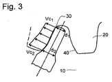
- FIG. 3 shows a schematic representation of the end mill 10 in the toothing of the workpiece in the form of a gear 20 with an involute toothing.
- the end mill 10 is mounted on the cutter head of the CNC gear cutting machine and rotated about the cutter axis A.
- the resulting tool speed is denoted by n and is given in revolutions / minute.
- the machine kinematics aligns the end mill 10 in accordance with the processing of the tooth flanks of the gear 20. Either the cutter or the tool holder together with the workpiece or both can be moved in combination.
- FIG. 4 shows the machine axes for alignment of the end mill 10.
- the cutter 10 is pivoted in the milling head 11 either from the central axis about the axis C2 and aligned almost parallel to the tooth flank of the gear 20 or laterally moved in the V1 direction and delivered in the X1 direction, to its longitudinal axis is aligned almost parallel to the tooth flank.
- the C1 axis must also be traversed.
- FIG. 3 it can be seen that the cutter axis A runs almost parallel to the involute 30 of the toothed wheel 20 to be produced.
- the novel shape of the end mill 10 in contrast to the conical cutter 1 of Figures 1 and 2 a cross-sectional profile that has only minor diameter deviations over the entire circumference of the cutter from the region of the tooth tip to the tooth root area along the axis A.
- the difference of the marked diameter d 1 , d 2 is relatively small, which is why, therefore, only slight differences in cutting speed occur over the entire length of the cutter blade.
- the cutting speed v c1 present in the area of the tooth root during machining is approximately equal in magnitude to the cutting speed v c2 in the region of the tooth tip.
- a partial machining of tooth flanks, as in the FIG. 5 shown is not part of the invention.
- profiles with different profile shapes see WO 2005/060650
- profile modifications such as head reductions, would be possible using an uncorrected milling cutter.
- the necessary CNC software is necessary for this type of processing anyway.
- v c ⁇ ⁇ d ⁇ n 1000 mm .
- d stands for the tool diameter
- n for the tool speed around the cutter axis A.
- the end mill 10 After completion of the involute tooth flank 30, the end mill 10 is realigned by the gear cutting machine, so that the cutter axis A runs parallel to the remaining tooth flank 40.
Landscapes
- Engineering & Computer Science (AREA)
- Mechanical Engineering (AREA)
- Gear Processing (AREA)
- Milling Processes (AREA)
Description
- Die Erfindung betrifft ein Verfahren zum Formfräsen einer Werkstückverzahnung, insbesondere eines Zahnrads auf einer Verzahnmaschine mit einem Fingerfräser.
- Zahnformfräser in Fingerform werden auf Verzahnmaschinen zum Verzahnen von Zahnrädern sowie zum Fräsen von Schnecken nach dem Formverfahren eingesetzt. Der Einsatz derartiger Fingerfräser beginnt bei Zahnrädern etwa bei Modul 10 und reicht bis zu den größten Verzahnabmessungen. Beim Fräsen von Schnecken werden diese Fingerfräser auch bei Schnecken und Schneckenrädern mit einem weit kleineren Modul eingesetzt.
- Auch zum Vorfräsen bei Großverzahnungen werden meist Werkzeuge in Fingerform oder noch besser Scheibenfräser verwendet. Fingerfräser werden vorzugsweise dort eingesetzt, wo andere Werkzeuge z.B. aus Kollisionsgründen ausscheiden, wie beispielsweise bei der Herstellung von geschlossenen Pfeilverzahnungen, bei Doppelschrägverzahnungen mit kleinem Zwischenraum oder Werkstücken, bei denen kein geeigneter Überlaufweg für ein scheiben- oder schneckenförmiges Werkzeug vorhanden ist, dies vor allem bei Verzahnungen mit großem bis sehr großem Modul. Zudem ist ein Fingerfräswerkzeug im Vergleich zu einem Wälzfräser in diesem Größenbereich recht preiswert. Damit ist das beschriebene Verfahren auch bei geringeren Losgrößen für Großverzahnungen interessant.
- Voraussetzung für den Einsatz von Fingerfräsern in einer Verzahnmaschine sind geeignete Aufnahmemittel. Die Verzahnmaschinen sind dazu mit einem passenden Fingerfräskopf ausgestattet, der den Fingerfräser aufnimmt und zur Rotation um seine Fräserachse antreibt. Bei bekannten Verzahnmaschinen verläuft die Fräserachse des Fingerfräsers senkrecht zur Werkstückachse des herzustellenden Zahnrades, wodurch die Herstellung echter Pfeilverzahnungen und Doppelschrägverzahnungen mit geringem oder keinem Zwischenraum mit Hilfe des Fingerfräsers ermöglicht wird.
- Die Fingerfräser weisen in der Regel ein kegelförmiges Profil auf, wobei sich der Profildurchmesser in Richtung der Stirnschneiden verjüngt. Ein Beispiel für einen bekannten Fingerfräser ist den beiden
Figuren 1 und 2 zu entnehmen. - Insbesondere
Figur 2 zeigt schematisch den Einsatz des Fingerfräsers 1 zur Herstellung einer Evolventen-Verzahnung am Zahnrad 2. Der Fingerfräser 1 wird mit seiner Längsachse senkrecht zur Werkstückachse ausgerichtet und rotiert zur einseitigen/beidseitigen Zahnflankenbearbeitung um seine Fräserachse B. Die Form des Fingerfräsers ist kegelförmig ausgeprägt, wobei sich der Durchmesser in Richtung der Stirnschneide 3 verjüngt. Der Durchmesser d2 des Fingerfräsers 1 im Bereich des Zahnkopfes 4 ist demnach verhältnismäßig groß gegenüber dem Durchmesser d1 im Bereich des Zahnfußes 5. - Die gewählte Profilform des Fingerfräsers 1 bewirkt eine variable Schnittgeschwindigkeit vc über den gesamten Umfang der Fräserschneide. Die Pfeile 6 charakterisieren das resultierende Schnittgeschwindigkeitsprofil entlang der Fräserachse B, wobei die betragsmäßig höchste Schnittgeschwindigkeit vc2 im Zahnkopfbereich und die minimale Schnittgeschwindigkeit vc1 im Zahnfußbereich anliegt. Die Auswahl einer optimalen Schnittgeschwindigkeit für die Rotationsbewegung ist bedingt durch den Durchmesserunterschied nicht möglich. Einerseits darf eine bestimmte Höchstgeschwindigkeit an der Fräserspitze nicht überschritten werden, andererseits ist eine bestimmte Mindestschnittgeschwindigkeit erforderlich.
- Als Konsequenz des vorliegenden Geschwindigkeitsprofils 6 tritt eine ungleichmäßige Abnutzung bzw. Abstumpfung der einzelnen Schneidenbereiche entlang der Fräserachse B auf. Dies macht ein häufiges Nachschärfen der Fingerfräserschneiden erforderlich, um eine ausreichende Bearbeitungsqualität gewährleisten zu können. Weiterhin wird die mögliche Fräserstandzeit davon nachteilig beeinträchtig. Nur durch Einstellung niedriger mittlerer Schnittgeschwindigkeiten mit Rücksicht auf die Schneidenteile mit großem Durchmesser kann die Fräserstandzeit verlängert werden. Um eine partielle Überlastung des Fräsers zu vermeiden, muss die Fräserdrehzahl dementsprechend angepaßt werden, was zu insgesamt längeren Bearbeitungszeiten führen kann.
- Aufgabe der vorliegenden Erfindung ist es, die vorstehend aufgezeigten Nachteile beim Formfräsen unter Verwendung von Fingerfräsern zu überwinden.
- Diese Aufgabe wird durch ein Verfahren zum Formfräsen einer Werkstückverzahnung, insbesondere Zahnrad, auf einer Verzahnmaschine mit einem Fingerfräser nach Anspruch 1 gelöst.
- Erfindungsgemäss verläuft die Fingerfräserachse in etwa parallel zur bearbeiteten Zahnflanke des Werkstückes und der Fingerfräser weist in Fräserachsenrichtung ein nahezu gleichbleibendes Durchmesserprofil_vom Zahnkopfbereich bis hin zum Zahnfussbereich entlang seiner Fräserachse auf, um eine annähernd gleichmässige Schnittgeschwindigkeit über der Fräserbreite und über die gesamte Zahnflanke des Werkstückes zu erreichen, wobei der Fingerfräser eine Aussenkontur zur Herstellung/Bearbeitung einer Evolventen- oder Zykloidenverzahnung aufweist.
- Hierdurch kann eine weitgehend konstante Schnittgeschwindigkeit über die gesamte Zahnflanke des zu erstellenden Werkstückes erreicht werden. Die Auswahl einer geeigneten Rotationsgeschwindigkeit des Fingerfräsers um seine Fräserachse wird zudem durch das erfindungsgemäße Verfahren erheblich vereinfacht, da ein Betrieb des Fräsers im optimalen Schnittgeschwindigkeitsbereich über die gesamte Schneidefläche möglich ist und nicht einzelne Teilbereiche gesondert berücksichtigt werden müssen. Ferner tritt eine regelmäßige Abnutzung entlang der gesamten Schneidefläche vom Zahnkopf bis hin zum Zahnfuß auf, was sich positiv auf die erreichbaren Fräserstandzeiten auswirkt. Insgesamt gesehen kann durch diesen Ansatz auch die Bearbeitungszeit für das Werkstück optimiert werden.
- Erfindungemäss wird das Verfahren mit dem Fingerfräser zur Herstellung von Verzahnungsprofilen mit zyklischen Kurven wie z.B. Evolventen- oder ZykloidVerzahnungen verwendet. Aufgrund der vorausgesetzten Parallelität von Fräserachse und der zyklischen Kurve bzw. Evolvente des herzustellenden Werkstückes ist demnach ein Querschnittsprofil des Fingerfräsers mit verhältnismäßig geringfügigen Durchmesserabweichungen entlang der Fräserachse notwendig. Folglich kann bei der Herstellung dieser Verzahnungen ein annähernd konstantes Schnittgeschwindigkeitsprofil über die gesamte Zahnflanke erzielt werden.
- Das Verfahren ist bevorzugt für eine einseitige Zahnflankenbearbeitung ausgelegt. Die Fräserachse des Fingerfräsers ist jeweils in etwa parallel zur zu bearbeitenden Zahnflanke verstellbar. Das Ausrichten des Fingerfräsers erfolgt entweder durch Verstellen des Fingerfräsers oder alternativ durch Verfahren des Werkstückes bzw. des Bearbeitungskopfes tangential zur Verzahnung. Eine kombinierte Verstellmöglichkeit des Fingerfräsers, des Bearbeitungskopfes sowie des Werkstückes ist ebenfalls denkbar.
- Mögliche Ausführungen des Fingerfräsers sind neben kompletten Fräsern aus einem Stück (Schaftwerkzeuge) auch zusammengesetzte Fräser wie z.B. Wendeschneidplattenfräser oder Fräser mit Wechselköpfen.
- In der Erfindung kann ein Fingerfräser zum Formfräsen einer Werkstückverzahnung, insbesondere Zahnradverzahnung oder ähnliche Profile angewendet werden. Dabei weist der Fingerfräser in Fräserachsenrichtung ein nahezu gleichbleibendes Durchmesserprofil auf, wodurch zur Werkstückbearbeitung eine in etwa parallele Ausrichtung der Fräserachse zur zu bearbeitenden Zahnflanke bzw. zum entsprechenden Zahnflankenabschnitt gewährleistet werden kann. Die konkrete Ausführung der Fräserschneide hängt von der herzustellenden Flankenform ab. Beispielsweise sind bei Fingerfräsern zur Evolventenverzahnung oder Zykloidverzahnungen geringfügige Schwankungen im Durchmesserprofil möglich. Im Gegensatz zu bekannten kegelförmigen Fingerfräsern fallen diese jedoch verhältnismäßig klein aus. Nur so kann ein nahezu konstantes Schnittgeschwindigkeitsprofil entlang der Fräserachse erreicht werden.
- Die Erfindung betrifft also ein Verfahren zum Formfräsen einer Werkstückverzahnung, insbesondere Zahnradverzahnung, das auf einer Verzahnmaschine mit einem Fingerfräser ausgeführt wird. Erfindungswesentlich an dem beanspruchten Verfahren ist, dass die Fräserachse in etwa parallel zur bearbeiteten Zahnflanke ausgerichtet wird, um eine annähernd konstante Schnittgeschwindigkeit über die gesamte Fräserbreite zu erzielen.
- Die erfindungsgemäße Vorgehensweise reduziert die Abnutzungserscheinungen am eingesetzten Fingerfräser bzw. hält diese über die gesamte Schneidelänge gleichmäßig. Ferner erlaubt das Verfahren eine vereinfachte Auswahl einer optimalen Schnittgeschwindigkeit zum Betrieb des Fingerfräsers, da die Durchmesserunterschiede entlang der Fräserachse nicht mehr so stark unterschiedlich sind. Damit können höhere Schnittgeschwindigkeiten gefahren werden, ohne dass die Gefahr einer partiellen Überlastung bestimmter Fräserbereiche besteht. Dies führt zu kürzeren Werkstückbearbeitungszeiten.
- Vorzugsweise verfolgt das erfindungsgemäße Verfahren eine einseitige Zahnflankenbearbeitung des herzustellenden Werkstücks bzw. eines Teilbereichs der Werkstückzahnflanke. Demnach wird der Fingerfräser nach jeder bearbeiteten Zahnflanke erneut ausgerichtet, um eine parallele Ausrichtung der Fräserachse zur nachfolgenden Zahnflanke zu gewährleisten.
- Weitere Vorteile und Einzelheiten der Erfindung werden anhand eines Ausführungsbeispiels und entsprechender Zeichnungen näher erläutert. Es zeigen:
- Fig. 1:
- Eine schematische Darstellung eines aus dem Stand der Technik bekannten Fingerfräsers,
- Fig. 2:
- eine Darstellung des Fingerfräsers aus
Fig. 1 in Bearbeitungsposition, - Fig. 3:
- eine Darstellung des erfindungsgemäßen Fingerfräsers in Bearbeitungsposition,
- Fig. 4:
- eine weitere Darstellung der Bearbeitungspositionen des Fingerfräsers und
- Fig. 5:
- eine Darstellung eines nicht zur Erfindung gehörigen Fingerfräsers in Bearbeitungsposition zur Bearbeitung eines Teilbereichs eines Zahnflankenprofils.
- Auf die
Figuren 1 und 2 wurde bereits im einleitenden Teil der Beschreibung eingegangen, weshalb in diesem Teil der Beschreibung nicht erneut Details zu den gezeigten Darstellungen ausgeführt werden sollen. -
Figur 3 zeigt eine schematische Darstellung des Fingerfräsers 10 bei der Verzahnung des Werkstückes in Form eines Zahnrades 20 mit einer Evolventenverzahnung. Der Fingerfräser 10 wird am Fräserkopf der CNC-Verzahnmaschine montiert und um die Fräserachse A in Rotation versetzt. Die resultierende Werkzeugdrehzahl wird mit n bezeichnet und wird in Umdrehungen/Minute angegeben. Die Maschinenkinematik richtet den Fingerfräser 10 entsprechend zur Bearbeitung der Zahnflanken des Zahnrades 20 aus. Dabei können entweder der Fräser bzw. die Werkzeugaufnahme samt Werkstück oder beide in Kombination verfahren werden. -
Figur 4 zeigt die Maschinenachsen zur Ausrichtung des Fingerfräsers 10. Der Fräser 10 wird im Fräskopf 11 entweder aus der Mittelachse um die Achse C2 herausgeschwenkt und nahezu parallel zur Zahnflanke des Zahnrades 20 ausgerichtet oder aber seitlich in V1-Richtung verfahren und in X1-Richtung zugestellt, bis seine Längsachse nahezu parallel zur Zahnflanke ausgerichtet ist. Bei schrägverzahnten Werkstücken oder bei Korrekturen der Zahnflanke über ihre Breite muss zusätzlich noch die C1-Achse verfahren werden. - Im Einzelnen ist der
Figur 3 zu entnehmen, dass die Fräserachse A nahezu parallel zur herzustellenden Evolvente 30 des Zahnrades 20 verläuft. Die neuartige Formgebung des Fingerfräsers 10 zeigt im Gegensatz zum kegelförmigen Fräser 1 derFiguren 1 und 2 ein Querschnittsprofil, das über den gesamte Fräserumfang vom Zahnkopfbereich bis hin zum Zahnfußbereich entlang der Achse A nur geringfügige Durchmesserabweichungen aufweist. - Die Differenz der gekennzeichneten Durchmesser d1, d2 ist verhältnismäßig klein, weshalb folglich nur geringfügige Schnittgeschwindigkeitsunterschiede über die gesamte Länge der Fräserschneide auftreten. Die während der Bearbeitung vorliegende Schnittgeschwindigkeit vc1 im Bereich des Zahnfußes ist dabei annähernd betragsgleich zur Schnittgeschwindigkeit vc2 im Bereich des Zahnkopfes.
- Eine teilweise Bearbeitung von Zahnflanken, wie in der
Figur 5 gezeigt, gehört nicht zur Erfindung. Hierlassen sich auch Profile mit unterschiedlichen Profilformen (sieheWO 2005/060650 ) über die Zahnhöhe bearbeiten oder auch asymmetrische Profile, wenn zwischen den Schnitten jeweils der Fräser 10 gewechselt wird. Ebenso wären Profilmodifikationen, wie z.B. Kopfrücknahmen unter Verwendung eines unkorrigierten Fräsers möglich. Die dazu notwendige CNC-Software ist für diese Art der Bearbeitung sowieso notwendig. - Die Berechnung der allgemein gültigen Schnittgeschwindigkeit vc erfolgt über folgende Formel:

- Nach der Fertigstellung der evolventenförmigen Zahnflanke 30 wird der Fingerfräser 10 durch die Verzahnmaschine neu ausgerichtet, so dass die Fräserachse A parallel zur verbleibenden Zahnflanke 40 verläuft.
- Ergänzend sei darauf hingewiesen, dass das erfindungsgemäße Verfahren ohne Weiteres bei der Verzahnung von Schnecken, Schneckenrädern oder Kegelrädern finden können.
Claims (2)
- Verfahren zum Formfräsen einer Werkstückverzahnung, insbesondere Zahnrad (20), auf einer Verzahnmaschine mit einem Fingerfräser (10),
dadurch gekennzeichnet,
dass die Fingerfräserachse (A) in etwa parallel zur bearbeiteten Zahnflanke (40) des Werkstückes verläuft, und dass der Fingerfräser (10) in Fräserachsenrichtung ein nahezu gleichbleibendes Durchmesserprofil vom Zahnkopfbereich bis hin zum Zahnfussbereich entlang seiner Fräserachse (A) aufweist, um eine annähernd gleichmässige Schnittgeschwindigkeit über der Fräserbreite und über die gesamte Zahnflanke (40) des Werkstückes zu erreichen, wobei der Fingerfräser (10) eine Aussenkontur zur Herstellung/Bearbeitung einer Evolventen- oder Zykloidenverzahnung aufweist. - Verfahren nach Anspruch 1, dadurch gekennzeichnet, dass eine einseitige Fräsbearbeitung der Zahnflanke (40) des Werkstückes erfolgt.
Applications Claiming Priority (1)
| Application Number | Priority Date | Filing Date | Title |
|---|---|---|---|
| DE102011017411A DE102011017411A1 (de) | 2011-04-18 | 2011-04-18 | Verzahnmaschine, Fingerfräser und Verfahren zum Formfräsen |
Publications (2)
| Publication Number | Publication Date |
|---|---|
| EP2514546A1 EP2514546A1 (de) | 2012-10-24 |
| EP2514546B1 true EP2514546B1 (de) | 2016-05-04 |
Family
ID=46027515
Family Applications (1)
| Application Number | Title | Priority Date | Filing Date |
|---|---|---|---|
| EP12002396.5A Not-in-force EP2514546B1 (de) | 2011-04-18 | 2012-04-02 | Verfahren zum Formfräsen |
Country Status (6)
| Country | Link |
|---|---|
| US (1) | US9573210B2 (de) |
| EP (1) | EP2514546B1 (de) |
| CN (1) | CN102744468B (de) |
| DE (1) | DE102011017411A1 (de) |
| ES (1) | ES2586154T3 (de) |
| RU (1) | RU2593882C2 (de) |
Families Citing this family (14)
| Publication number | Priority date | Publication date | Assignee | Title |
|---|---|---|---|---|
| DE102010023728A1 (de) * | 2010-06-14 | 2011-12-15 | Liebherr-Verzahntechnik Gmbh | Verfahren zum Herstellen einer Mehrzahl von identischen Zahnrädern mittles abspanender Bearbeitung |
| DE112013005198T5 (de) * | 2012-10-30 | 2015-09-10 | Concepts Eti, Inc. | Verfahren, Systeme und Vorrichtungen zur Gestaltung und Herstellung von flankenfräsbaren Bauteilen |
| WO2014182618A1 (en) * | 2013-05-06 | 2014-11-13 | Dmg Mori Seiki Advanced Solutions, Inc. | Generative gear machining method and apparatus |
| EP3043945B1 (de) * | 2013-09-11 | 2021-09-29 | Profilator GmbH & Co. KG | Wälzschälverfahren und zugehörige vorrichtung |
| US9597743B2 (en) | 2014-01-17 | 2017-03-21 | Sikorsky Aircraft Corporation | Machine for machining gear teeth and gear teeth machining method |
| US9465530B2 (en) | 2014-04-22 | 2016-10-11 | Concepts Nrec, Llc | Methods, systems, and devices for designing and manufacturing flank millable components |
| CN106216780A (zh) * | 2016-08-24 | 2016-12-14 | 西安工业大学 | 一种新型齿轮加工刀具 |
| CN107617768B (zh) * | 2017-08-22 | 2019-04-19 | 成都飞机工业(集团)有限责任公司 | 一种适用于数控车削中心的矩形外花键加工方法 |
| DE102018108622A1 (de) | 2018-04-11 | 2019-10-17 | Liebherr-Verzahntechnik Gmbh | Vorrichtung zur Anfasbearbeitung eines Werkstücks |
| CN109465501A (zh) * | 2018-12-04 | 2019-03-15 | 重庆机床(集团)有限责任公司 | 一种齿轮铣棱刀具及其使用方法 |
| CN110449668B (zh) * | 2019-09-04 | 2025-04-15 | 江苏科比特科技有限公司 | 一种高效齿轮铣刀 |
| USD923675S1 (en) * | 2020-03-11 | 2021-06-29 | Conprofe Technology Group Co., Ltd. | Head for end mill |
| CN111687496B (zh) * | 2020-05-25 | 2021-10-08 | 西安交通大学 | 一种窄空刀槽人字齿轮偏距成形加工方法 |
| CN114603212A (zh) * | 2022-02-25 | 2022-06-10 | 秦川机床工具集团股份公司 | 一种渐开线人字齿加工方法及指状成型铣齿刀 |
Citations (2)
| Publication number | Priority date | Publication date | Assignee | Title |
|---|---|---|---|---|
| WO2008133517A1 (en) | 2007-04-26 | 2008-11-06 | Hpg Nederland B.V. | Method for designing and manufacturing a gear |
| WO2012002396A1 (ja) | 2010-06-30 | 2012-01-05 | 日本ゼオン株式会社 | 非水系電池電極用バインダー組成物、非水系電池用電解液組成物及びその利用 |
Family Cites Families (15)
| Publication number | Priority date | Publication date | Assignee | Title |
|---|---|---|---|---|
| US2315147A (en) * | 1937-09-17 | 1943-03-30 | Gleason Works | Cutter for and method of cutting gears |
| US2737855A (en) * | 1951-10-18 | 1956-03-13 | Laval Steam Turbine Co | Portable gear tooth finishing machine |
| SU521084A1 (ru) * | 1972-04-11 | 1976-07-15 | Ростовский-На-Дону Государственный Университет | Способ нарезани круговых зубьев цилиндрических колес |
| SU1715520A1 (ru) * | 1987-11-19 | 1992-02-28 | Всесоюзный заочный машиностроительный институт | Универсальный зубообрабатывающий станок с ЧПУ |
| US4949456A (en) * | 1989-01-06 | 1990-08-21 | Eaton Corporation | Method of making ring gear and ring gear therefrom |
| US5681207A (en) * | 1993-07-23 | 1997-10-28 | Nishida; Noriteru | Method of working a helical gear by grinding |
| US6204466B1 (en) * | 1997-09-23 | 2001-03-20 | G.W. Plastics, Inc. | EDM electrode for creating a gear tooth form having a tooth shape in a cavity component and method of making an EDM electrode |
| DE19903481A1 (de) | 1999-01-28 | 2000-08-03 | Dre Con Groswaelzlager Gmbh | Vorrichtung und Verfahren zur Herstellung von Verzahnungen |
| DE50006701D1 (de) * | 1999-12-01 | 2004-07-08 | Lambert Ag Safnern | Formschneidverfahren für geradverzahnte kegelräder |
| DE602004008332T2 (de) | 2003-12-18 | 2008-05-21 | Genesis Partners, L.P. | Zahnradzahnprofilkrümmung |
| EP1864739B1 (de) * | 2006-06-06 | 2009-03-11 | Klingelnberg GmbH | Vorrichtung und Verfahren zur Weichbearbeitung von Kegelrädern und Verwendung der Vorrichtung |
| RU2322329C1 (ru) * | 2006-06-14 | 2008-04-20 | ООО Научно-производственное объединение "Зубчатые трансмиссии" | Способ изготовления цилиндрических колес с арочными зубьями |
| CN201253717Y (zh) * | 2008-09-19 | 2009-06-10 | 中国有色(沈阳)冶金机械有限公司 | 一种指形齿轮铣刀 |
| AT508493B1 (de) | 2009-06-19 | 2012-09-15 | Wfl Millturn Tech Gmbh & Co Kg | Verfahren und werkzeugvorrichtung zum profilfräsen |
| DE102010061432B4 (de) | 2010-12-21 | 2014-02-06 | Gebr. Heller Maschinenfabrik Gmbh | Verfahren und Werkzeug zur Herstellung eines Zahnrades mit balligen Zähnen |
-
2011
- 2011-04-18 DE DE102011017411A patent/DE102011017411A1/de not_active Withdrawn
-
2012
- 2012-04-02 ES ES12002396.5T patent/ES2586154T3/es active Active
- 2012-04-02 EP EP12002396.5A patent/EP2514546B1/de not_active Not-in-force
- 2012-04-05 RU RU2012113305/02A patent/RU2593882C2/ru not_active IP Right Cessation
- 2012-04-17 CN CN201210113415.0A patent/CN102744468B/zh not_active Expired - Fee Related
- 2012-04-17 US US13/449,158 patent/US9573210B2/en not_active Expired - Fee Related
Patent Citations (2)
| Publication number | Priority date | Publication date | Assignee | Title |
|---|---|---|---|---|
| WO2008133517A1 (en) | 2007-04-26 | 2008-11-06 | Hpg Nederland B.V. | Method for designing and manufacturing a gear |
| WO2012002396A1 (ja) | 2010-06-30 | 2012-01-05 | 日本ゼオン株式会社 | 非水系電池電極用バインダー組成物、非水系電池用電解液組成物及びその利用 |
Also Published As
| Publication number | Publication date |
|---|---|
| US9573210B2 (en) | 2017-02-21 |
| EP2514546A1 (de) | 2012-10-24 |
| RU2012113305A (ru) | 2013-10-10 |
| DE102011017411A1 (de) | 2012-10-18 |
| US20130101367A1 (en) | 2013-04-25 |
| RU2593882C2 (ru) | 2016-08-10 |
| CN102744468B (zh) | 2017-06-23 |
| ES2586154T3 (es) | 2016-10-11 |
| CN102744468A (zh) | 2012-10-24 |
Similar Documents
| Publication | Publication Date | Title |
|---|---|---|
| EP2514546A1 (de) | Verzahnmaschine, Fingerfräser und Verfahren zum Formfräsen | |
| EP2520391B1 (de) | Verfahren zum Wälzschälen | |
| EP2570217B1 (de) | Semi-Completing Wälzschälverfahren und Vorrichtung mit entsprechendem Wälzschälwerkzeug zum Ausführen eines Semi-Completing Wälzschälverfahrens | |
| DE10330474B4 (de) | Vorrichtung zur Herstellung eines Zahnrads aus einem Zahnradrohling | |
| EP1987919B1 (de) | Verfahren und schleifmaschine zum profilieren eines schleifwerkzeugs | |
| EP2385885B2 (de) | Vorrichtung und verfahren zum verzahnen von werkstücken | |
| EP2665574B1 (de) | Verfahren des wälzschälens oder hartschälens eines werkstückes und dazu ausgelegte werkzeugmaschine | |
| EP2537615B1 (de) | Robustes Verfahren zum Wälzschälen | |
| EP3389906B1 (de) | Vorrichtung und verfahren zur fertigung einer fase an einem verzahnten werkrad | |
| EP3271100B1 (de) | Verzahnungsverfahren mit zahnnachbearbeitung und kombiwerkzeug dafür | |
| DE102014018328B4 (de) | Verfahren zum bearbeiten einer verzahnung, werkzeuganordnung und verzahnungsmaschine | |
| EP3546101B1 (de) | Verfahren und vorrichtung zum verzahnen von werkrädern durch wälzschälen | |
| EP3241640B1 (de) | Verfahren zum hartfeinbearbeiten der verzahnung eines zahnrads oder eines zahnradähnlichen profils eines werkstücks | |
| EP2596893A1 (de) | Semi-Completing-Wälzschälverfahren mit zwei Achskreuzwinkeln und Verwendung eines entsprechenden Wälzschälwerkzeugs zum Semi-Completing-Wälzschälen | |
| WO2019011871A1 (de) | Verfahren zum erzeugen eines verzahnten werkstücks, sowie dazu geeignete steuerprogramm, wekzeuge und verzahnungsmaschine | |
| EP3034219A1 (de) | Wälzschälverfahren mit Mehrschnittstrategie | |
| EP2537616B1 (de) | Robustes Verfahren zum Wälzschälen und entsprechende Vorrichtung mit Wälzschälwerkzeug | |
| DE20320294U1 (de) | Vorrichtung zur Herstellung eines Zahnrads | |
| DE10230148B4 (de) | Verfahren zum Bearbeiten von mittels Wälzfräsen hergestellten Zahnrädern | |
| EP3206822B1 (de) | Verfahren zum abrichten eines honwerkzeugs und verfahren zum honen eines zahnrads | |
| EP2370227B1 (de) | Vorrichtung und verzahnen von werkrädern mit einem konischen wälzfräser | |
| DE102013003964A1 (de) | Verzahnmaschine mit Doppelbearbeitungskopf | |
| DE4340608B4 (de) | Schneidmesser und Verwendung von Schneidmessern zur Erzeugung von Zähnen von Spiralkegelrädern und Hypoid-Zahnrädern oder Ritzeln | |
| EP2442937B1 (de) | Verfahren und werkzeugvorrichtung zum profilfräsen | |
| EP3517235B1 (de) | Verfahren zum entgraten von kegelrädern und cnc-verzahnmaschine mit einer entsprechenden software zum entgraten |
Legal Events
| Date | Code | Title | Description |
|---|---|---|---|
| PUAI | Public reference made under article 153(3) epc to a published international application that has entered the european phase |
Free format text: ORIGINAL CODE: 0009012 |
|
| AK | Designated contracting states |
Kind code of ref document: A1 Designated state(s): AL AT BE BG CH CY CZ DE DK EE ES FI FR GB GR HR HU IE IS IT LI LT LU LV MC MK MT NL NO PL PT RO RS SE SI SK SM TR |
|
| AX | Request for extension of the european patent |
Extension state: BA ME |
|
| 17P | Request for examination filed |
Effective date: 20130424 |
|
| 17Q | First examination report despatched |
Effective date: 20140916 |
|
| GRAP | Despatch of communication of intention to grant a patent |
Free format text: ORIGINAL CODE: EPIDOSNIGR1 |
|
| INTG | Intention to grant announced |
Effective date: 20160202 |
|
| RIN1 | Information on inventor provided before grant (corrected) |
Inventor name: MUNDT, ALOIS |
|
| GRAS | Grant fee paid |
Free format text: ORIGINAL CODE: EPIDOSNIGR3 |
|
| GRAA | (expected) grant |
Free format text: ORIGINAL CODE: 0009210 |
|
| AK | Designated contracting states |
Kind code of ref document: B1 Designated state(s): AL AT BE BG CH CY CZ DE DK EE ES FI FR GB GR HR HU IE IS IT LI LT LU LV MC MK MT NL NO PL PT RO RS SE SI SK SM TR |
|
| REG | Reference to a national code |
Ref country code: GB Ref legal event code: FG4D Free format text: NOT ENGLISH |
|
| REG | Reference to a national code |
Ref country code: CH Ref legal event code: EP |
|
| REG | Reference to a national code |
Ref country code: AT Ref legal event code: REF Ref document number: 796459 Country of ref document: AT Kind code of ref document: T Effective date: 20160515 |
|
| REG | Reference to a national code |
Ref country code: IE Ref legal event code: FG4D Free format text: LANGUAGE OF EP DOCUMENT: GERMAN |
|
| REG | Reference to a national code |
Ref country code: DE Ref legal event code: R096 Ref document number: 502012006973 Country of ref document: DE |
|
| REG | Reference to a national code |
Ref country code: NL Ref legal event code: FP |
|
| REG | Reference to a national code |
Ref country code: LT Ref legal event code: MG4D |
|
| REG | Reference to a national code |
Ref country code: ES Ref legal event code: FG2A Ref document number: 2586154 Country of ref document: ES Kind code of ref document: T3 Effective date: 20161011 |
|
| PG25 | Lapsed in a contracting state [announced via postgrant information from national office to epo] |
Ref country code: LT Free format text: LAPSE BECAUSE OF FAILURE TO SUBMIT A TRANSLATION OF THE DESCRIPTION OR TO PAY THE FEE WITHIN THE PRESCRIBED TIME-LIMIT Effective date: 20160504 Ref country code: NO Free format text: LAPSE BECAUSE OF FAILURE TO SUBMIT A TRANSLATION OF THE DESCRIPTION OR TO PAY THE FEE WITHIN THE PRESCRIBED TIME-LIMIT Effective date: 20160804 Ref country code: FI Free format text: LAPSE BECAUSE OF FAILURE TO SUBMIT A TRANSLATION OF THE DESCRIPTION OR TO PAY THE FEE WITHIN THE PRESCRIBED TIME-LIMIT Effective date: 20160504 |
|
| PG25 | Lapsed in a contracting state [announced via postgrant information from national office to epo] |
Ref country code: HR Free format text: LAPSE BECAUSE OF FAILURE TO SUBMIT A TRANSLATION OF THE DESCRIPTION OR TO PAY THE FEE WITHIN THE PRESCRIBED TIME-LIMIT Effective date: 20160504 Ref country code: GR Free format text: LAPSE BECAUSE OF FAILURE TO SUBMIT A TRANSLATION OF THE DESCRIPTION OR TO PAY THE FEE WITHIN THE PRESCRIBED TIME-LIMIT Effective date: 20160805 Ref country code: LV Free format text: LAPSE BECAUSE OF FAILURE TO SUBMIT A TRANSLATION OF THE DESCRIPTION OR TO PAY THE FEE WITHIN THE PRESCRIBED TIME-LIMIT Effective date: 20160504 Ref country code: RS Free format text: LAPSE BECAUSE OF FAILURE TO SUBMIT A TRANSLATION OF THE DESCRIPTION OR TO PAY THE FEE WITHIN THE PRESCRIBED TIME-LIMIT Effective date: 20160504 Ref country code: PT Free format text: LAPSE BECAUSE OF FAILURE TO SUBMIT A TRANSLATION OF THE DESCRIPTION OR TO PAY THE FEE WITHIN THE PRESCRIBED TIME-LIMIT Effective date: 20160905 Ref country code: SE Free format text: LAPSE BECAUSE OF FAILURE TO SUBMIT A TRANSLATION OF THE DESCRIPTION OR TO PAY THE FEE WITHIN THE PRESCRIBED TIME-LIMIT Effective date: 20160504 |
|
| PG25 | Lapsed in a contracting state [announced via postgrant information from national office to epo] |
Ref country code: DK Free format text: LAPSE BECAUSE OF FAILURE TO SUBMIT A TRANSLATION OF THE DESCRIPTION OR TO PAY THE FEE WITHIN THE PRESCRIBED TIME-LIMIT Effective date: 20160504 Ref country code: SK Free format text: LAPSE BECAUSE OF FAILURE TO SUBMIT A TRANSLATION OF THE DESCRIPTION OR TO PAY THE FEE WITHIN THE PRESCRIBED TIME-LIMIT Effective date: 20160504 Ref country code: RO Free format text: LAPSE BECAUSE OF FAILURE TO SUBMIT A TRANSLATION OF THE DESCRIPTION OR TO PAY THE FEE WITHIN THE PRESCRIBED TIME-LIMIT Effective date: 20160504 Ref country code: CZ Free format text: LAPSE BECAUSE OF FAILURE TO SUBMIT A TRANSLATION OF THE DESCRIPTION OR TO PAY THE FEE WITHIN THE PRESCRIBED TIME-LIMIT Effective date: 20160504 Ref country code: EE Free format text: LAPSE BECAUSE OF FAILURE TO SUBMIT A TRANSLATION OF THE DESCRIPTION OR TO PAY THE FEE WITHIN THE PRESCRIBED TIME-LIMIT Effective date: 20160504 |
|
| REG | Reference to a national code |
Ref country code: DE Ref legal event code: R026 Ref document number: 502012006973 Country of ref document: DE |
|
| PLBI | Opposition filed |
Free format text: ORIGINAL CODE: 0009260 |
|
| PG25 | Lapsed in a contracting state [announced via postgrant information from national office to epo] |
Ref country code: PL Free format text: LAPSE BECAUSE OF FAILURE TO SUBMIT A TRANSLATION OF THE DESCRIPTION OR TO PAY THE FEE WITHIN THE PRESCRIBED TIME-LIMIT Effective date: 20160504 Ref country code: SM Free format text: LAPSE BECAUSE OF FAILURE TO SUBMIT A TRANSLATION OF THE DESCRIPTION OR TO PAY THE FEE WITHIN THE PRESCRIBED TIME-LIMIT Effective date: 20160504 |
|
| PLAX | Notice of opposition and request to file observation + time limit sent |
Free format text: ORIGINAL CODE: EPIDOSNOBS2 |
|
| 26 | Opposition filed |
Opponent name: EUKLID CAD/CAM AG Effective date: 20170206 |
|
| REG | Reference to a national code |
Ref country code: FR Ref legal event code: PLFP Year of fee payment: 6 |
|
| PG25 | Lapsed in a contracting state [announced via postgrant information from national office to epo] |
Ref country code: SI Free format text: LAPSE BECAUSE OF FAILURE TO SUBMIT A TRANSLATION OF THE DESCRIPTION OR TO PAY THE FEE WITHIN THE PRESCRIBED TIME-LIMIT Effective date: 20160504 |
|
| PLAF | Information modified related to communication of a notice of opposition and request to file observations + time limit |
Free format text: ORIGINAL CODE: EPIDOSCOBS2 |
|
| PLBB | Reply of patent proprietor to notice(s) of opposition received |
Free format text: ORIGINAL CODE: EPIDOSNOBS3 |
|
| PG25 | Lapsed in a contracting state [announced via postgrant information from national office to epo] |
Ref country code: MC Free format text: LAPSE BECAUSE OF FAILURE TO SUBMIT A TRANSLATION OF THE DESCRIPTION OR TO PAY THE FEE WITHIN THE PRESCRIBED TIME-LIMIT Effective date: 20160504 |
|
| REG | Reference to a national code |
Ref country code: CH Ref legal event code: PL |
|
| PLBP | Opposition withdrawn |
Free format text: ORIGINAL CODE: 0009264 |
|
| REG | Reference to a national code |
Ref country code: IE Ref legal event code: MM4A |
|
| PLBD | Termination of opposition procedure: decision despatched |
Free format text: ORIGINAL CODE: EPIDOSNOPC1 |
|
| PG25 | Lapsed in a contracting state [announced via postgrant information from national office to epo] |
Ref country code: CH Free format text: LAPSE BECAUSE OF NON-PAYMENT OF DUE FEES Effective date: 20170430 Ref country code: LI Free format text: LAPSE BECAUSE OF NON-PAYMENT OF DUE FEES Effective date: 20170430 Ref country code: LU Free format text: LAPSE BECAUSE OF NON-PAYMENT OF DUE FEES Effective date: 20170402 |
|
| REG | Reference to a national code |
Ref country code: DE Ref legal event code: R100 Ref document number: 502012006973 Country of ref document: DE |
|
| REG | Reference to a national code |
Ref country code: BE Ref legal event code: MM Effective date: 20170430 |
|
| REG | Reference to a national code |
Ref country code: FR Ref legal event code: PLFP Year of fee payment: 7 |
|
| PG25 | Lapsed in a contracting state [announced via postgrant information from national office to epo] |
Ref country code: IE Free format text: LAPSE BECAUSE OF NON-PAYMENT OF DUE FEES Effective date: 20170402 |
|
| PGFP | Annual fee paid to national office [announced via postgrant information from national office to epo] |
Ref country code: GB Payment date: 20180326 Year of fee payment: 7 |
|
| PG25 | Lapsed in a contracting state [announced via postgrant information from national office to epo] |
Ref country code: BE Free format text: LAPSE BECAUSE OF NON-PAYMENT OF DUE FEES Effective date: 20170430 |
|
| PLBM | Termination of opposition procedure: date of legal effect published |
Free format text: ORIGINAL CODE: 0009276 |
|
| STAA | Information on the status of an ep patent application or granted ep patent |
Free format text: STATUS: OPPOSITION PROCEDURE CLOSED |
|
| REG | Reference to a national code |
Ref country code: AT Ref legal event code: MM01 Ref document number: 796459 Country of ref document: AT Kind code of ref document: T Effective date: 20170402 |
|
| PGFP | Annual fee paid to national office [announced via postgrant information from national office to epo] |
Ref country code: NL Payment date: 20180427 Year of fee payment: 7 |
|
| 27C | Opposition proceedings terminated |
Effective date: 20180301 |
|
| PGFP | Annual fee paid to national office [announced via postgrant information from national office to epo] |
Ref country code: ES Payment date: 20180518 Year of fee payment: 7 |
|
| PG25 | Lapsed in a contracting state [announced via postgrant information from national office to epo] |
Ref country code: AT Free format text: LAPSE BECAUSE OF NON-PAYMENT OF DUE FEES Effective date: 20170402 |
|
| PGFP | Annual fee paid to national office [announced via postgrant information from national office to epo] |
Ref country code: FR Payment date: 20180426 Year of fee payment: 7 |
|
| PG25 | Lapsed in a contracting state [announced via postgrant information from national office to epo] |
Ref country code: MT Free format text: LAPSE BECAUSE OF FAILURE TO SUBMIT A TRANSLATION OF THE DESCRIPTION OR TO PAY THE FEE WITHIN THE PRESCRIBED TIME-LIMIT Effective date: 20160504 |
|
| PG25 | Lapsed in a contracting state [announced via postgrant information from national office to epo] |
Ref country code: AL Free format text: LAPSE BECAUSE OF FAILURE TO SUBMIT A TRANSLATION OF THE DESCRIPTION OR TO PAY THE FEE WITHIN THE PRESCRIBED TIME-LIMIT Effective date: 20160504 |
|
| PG25 | Lapsed in a contracting state [announced via postgrant information from national office to epo] |
Ref country code: HU Free format text: LAPSE BECAUSE OF FAILURE TO SUBMIT A TRANSLATION OF THE DESCRIPTION OR TO PAY THE FEE WITHIN THE PRESCRIBED TIME-LIMIT; INVALID AB INITIO Effective date: 20120402 |
|
| PGFP | Annual fee paid to national office [announced via postgrant information from national office to epo] |
Ref country code: IT Payment date: 20190430 Year of fee payment: 8 |
|
| PG25 | Lapsed in a contracting state [announced via postgrant information from national office to epo] |
Ref country code: BG Free format text: LAPSE BECAUSE OF FAILURE TO SUBMIT A TRANSLATION OF THE DESCRIPTION OR TO PAY THE FEE WITHIN THE PRESCRIBED TIME-LIMIT Effective date: 20160504 |
|
| PG25 | Lapsed in a contracting state [announced via postgrant information from national office to epo] |
Ref country code: CY Free format text: LAPSE BECAUSE OF NON-PAYMENT OF DUE FEES Effective date: 20160504 |
|
| PG25 | Lapsed in a contracting state [announced via postgrant information from national office to epo] |
Ref country code: MK Free format text: LAPSE BECAUSE OF FAILURE TO SUBMIT A TRANSLATION OF THE DESCRIPTION OR TO PAY THE FEE WITHIN THE PRESCRIBED TIME-LIMIT Effective date: 20160504 |
|
| REG | Reference to a national code |
Ref country code: NL Ref legal event code: MM Effective date: 20190501 |
|
| GBPC | Gb: european patent ceased through non-payment of renewal fee |
Effective date: 20190402 |
|
| PG25 | Lapsed in a contracting state [announced via postgrant information from national office to epo] |
Ref country code: NL Free format text: LAPSE BECAUSE OF NON-PAYMENT OF DUE FEES Effective date: 20190501 Ref country code: GB Free format text: LAPSE BECAUSE OF NON-PAYMENT OF DUE FEES Effective date: 20190402 |
|
| PG25 | Lapsed in a contracting state [announced via postgrant information from national office to epo] |
Ref country code: FR Free format text: LAPSE BECAUSE OF NON-PAYMENT OF DUE FEES Effective date: 20190430 |
|
| PG25 | Lapsed in a contracting state [announced via postgrant information from national office to epo] |
Ref country code: TR Free format text: LAPSE BECAUSE OF FAILURE TO SUBMIT A TRANSLATION OF THE DESCRIPTION OR TO PAY THE FEE WITHIN THE PRESCRIBED TIME-LIMIT Effective date: 20160504 |
|
| PG25 | Lapsed in a contracting state [announced via postgrant information from national office to epo] |
Ref country code: IS Free format text: LAPSE BECAUSE OF FAILURE TO SUBMIT A TRANSLATION OF THE DESCRIPTION OR TO PAY THE FEE WITHIN THE PRESCRIBED TIME-LIMIT Effective date: 20160904 |
|
| PGFP | Annual fee paid to national office [announced via postgrant information from national office to epo] |
Ref country code: DE Payment date: 20200429 Year of fee payment: 9 |
|
| REG | Reference to a national code |
Ref country code: ES Ref legal event code: FD2A Effective date: 20200828 |
|
| PG25 | Lapsed in a contracting state [announced via postgrant information from national office to epo] |
Ref country code: ES Free format text: LAPSE BECAUSE OF NON-PAYMENT OF DUE FEES Effective date: 20190403 |
|
| PG25 | Lapsed in a contracting state [announced via postgrant information from national office to epo] |
Ref country code: IT Free format text: LAPSE BECAUSE OF NON-PAYMENT OF DUE FEES Effective date: 20200402 |
|
| REG | Reference to a national code |
Ref country code: DE Ref legal event code: R119 Ref document number: 502012006973 Country of ref document: DE |
|
| PG25 | Lapsed in a contracting state [announced via postgrant information from national office to epo] |
Ref country code: DE Free format text: LAPSE BECAUSE OF NON-PAYMENT OF DUE FEES Effective date: 20211103 |