EP2513535B1 - Micro-fluidic system - Google Patents
Micro-fluidic system Download PDFInfo
- Publication number
- EP2513535B1 EP2513535B1 EP10818088.6A EP10818088A EP2513535B1 EP 2513535 B1 EP2513535 B1 EP 2513535B1 EP 10818088 A EP10818088 A EP 10818088A EP 2513535 B1 EP2513535 B1 EP 2513535B1
- Authority
- EP
- European Patent Office
- Prior art keywords
- closing element
- segment
- hole
- partition
- micro
- Prior art date
- Legal status (The legal status is an assumption and is not a legal conclusion. Google has not performed a legal analysis and makes no representation as to the accuracy of the status listed.)
- Active
Links
- 238000005192 partition Methods 0.000 claims description 36
- 229920001971 elastomer Polymers 0.000 claims description 8
- 239000000806 elastomer Substances 0.000 claims description 8
- 239000000853 adhesive Substances 0.000 claims description 7
- 230000001070 adhesive effect Effects 0.000 claims description 7
- 238000000034 method Methods 0.000 claims description 7
- 239000012530 fluid Substances 0.000 claims description 6
- 229920001296 polysiloxane Polymers 0.000 claims description 6
- 230000008878 coupling Effects 0.000 claims description 5
- 238000010168 coupling process Methods 0.000 claims description 5
- 238000005859 coupling reaction Methods 0.000 claims description 5
- 230000000284 resting effect Effects 0.000 claims description 4
- 238000009832 plasma treatment Methods 0.000 claims description 3
- 238000011144 upstream manufacturing Methods 0.000 claims description 3
- 239000013013 elastic material Substances 0.000 claims description 2
- 125000001495 ethyl group Chemical group [H]C([H])([H])C([H])([H])* 0.000 claims description 2
- 125000002496 methyl group Chemical group [H]C([H])([H])* 0.000 claims description 2
- 230000002093 peripheral effect Effects 0.000 claims description 2
- 125000001436 propyl group Chemical group [H]C([*])([H])C([H])([H])C([H])([H])[H] 0.000 claims description 2
- 229920002379 silicone rubber Polymers 0.000 claims description 2
- 239000004945 silicone rubber Substances 0.000 claims description 2
- 239000000463 material Substances 0.000 description 16
- 229920002120 photoresistant polymer Polymers 0.000 description 13
- 239000004205 dimethyl polysiloxane Substances 0.000 description 11
- 229920000435 poly(dimethylsiloxane) Polymers 0.000 description 11
- 238000004519 manufacturing process Methods 0.000 description 8
- 125000006850 spacer group Chemical group 0.000 description 8
- 239000012528 membrane Substances 0.000 description 7
- 239000000203 mixture Substances 0.000 description 7
- NIXOWILDQLNWCW-UHFFFAOYSA-N acrylic acid group Chemical group C(C=C)(=O)O NIXOWILDQLNWCW-UHFFFAOYSA-N 0.000 description 6
- 229920000058 polyacrylate Polymers 0.000 description 6
- 239000000178 monomer Substances 0.000 description 5
- -1 buthylmethacrilate Chemical compound 0.000 description 4
- BAPJBEWLBFYGME-UHFFFAOYSA-N Methyl acrylate Chemical compound COC(=O)C=C BAPJBEWLBFYGME-UHFFFAOYSA-N 0.000 description 3
- 239000011521 glass Substances 0.000 description 3
- 229920000642 polymer Polymers 0.000 description 3
- 241000463291 Elga Species 0.000 description 2
- XUIMIQQOPSSXEZ-UHFFFAOYSA-N Silicon Chemical compound [Si] XUIMIQQOPSSXEZ-UHFFFAOYSA-N 0.000 description 2
- 239000003795 chemical substances by application Substances 0.000 description 2
- 239000013536 elastomeric material Substances 0.000 description 2
- 230000005670 electromagnetic radiation Effects 0.000 description 2
- 239000007788 liquid Substances 0.000 description 2
- 230000005855 radiation Effects 0.000 description 2
- 238000007789 sealing Methods 0.000 description 2
- 229910052710 silicon Inorganic materials 0.000 description 2
- 239000010703 silicon Substances 0.000 description 2
- VMAWODUEPLAHOE-UHFFFAOYSA-N 2,4,6,8-tetrakis(ethenyl)-2,4,6,8-tetramethyl-1,3,5,7,2,4,6,8-tetraoxatetrasilocane Chemical compound C=C[Si]1(C)O[Si](C)(C=C)O[Si](C)(C=C)O[Si](C)(C=C)O1 VMAWODUEPLAHOE-UHFFFAOYSA-N 0.000 description 1
- SMZOUWXMTYCWNB-UHFFFAOYSA-N 2-(2-methoxy-5-methylphenyl)ethanamine Chemical compound COC1=CC=C(C)C=C1CCN SMZOUWXMTYCWNB-UHFFFAOYSA-N 0.000 description 1
- NQBXSWAWVZHKBZ-UHFFFAOYSA-N 2-butoxyethyl acetate Chemical compound CCCCOCCOC(C)=O NQBXSWAWVZHKBZ-UHFFFAOYSA-N 0.000 description 1
- CERQOIWHTDAKMF-UHFFFAOYSA-N Methacrylic acid Chemical compound CC(=C)C(O)=O CERQOIWHTDAKMF-UHFFFAOYSA-N 0.000 description 1
- VVQNEPGJFQJSBK-UHFFFAOYSA-N Methyl methacrylate Chemical compound COC(=O)C(C)=C VVQNEPGJFQJSBK-UHFFFAOYSA-N 0.000 description 1
- CTQNGGLPUBDAKN-UHFFFAOYSA-N O-Xylene Chemical compound CC1=CC=CC=C1C CTQNGGLPUBDAKN-UHFFFAOYSA-N 0.000 description 1
- 125000005907 alkyl ester group Chemical group 0.000 description 1
- 125000000217 alkyl group Chemical group 0.000 description 1
- 125000004432 carbon atom Chemical group C* 0.000 description 1
- 230000000295 complement effect Effects 0.000 description 1
- 230000006835 compression Effects 0.000 description 1
- 238000007906 compression Methods 0.000 description 1
- 238000004132 cross linking Methods 0.000 description 1
- 230000001419 dependent effect Effects 0.000 description 1
- URQUNWYOBNUYJQ-UHFFFAOYSA-N diazonaphthoquinone Chemical compound C1=CC=C2C(=O)C(=[N]=[N])C=CC2=C1 URQUNWYOBNUYJQ-UHFFFAOYSA-N 0.000 description 1
- 238000007598 dipping method Methods 0.000 description 1
- 238000006073 displacement reaction Methods 0.000 description 1
- 238000001035 drying Methods 0.000 description 1
- 238000005265 energy consumption Methods 0.000 description 1
- SUPCQIBBMFXVTL-UHFFFAOYSA-N ethyl 2-methylprop-2-enoate Chemical compound CCOC(=O)C(C)=C SUPCQIBBMFXVTL-UHFFFAOYSA-N 0.000 description 1
- SLGWESQGEUXWJQ-UHFFFAOYSA-N formaldehyde;phenol Chemical compound O=C.OC1=CC=CC=C1 SLGWESQGEUXWJQ-UHFFFAOYSA-N 0.000 description 1
- 238000011065 in-situ storage Methods 0.000 description 1
- 238000003801 milling Methods 0.000 description 1
- SYSQUGFVNFXIIT-UHFFFAOYSA-N n-[4-(1,3-benzoxazol-2-yl)phenyl]-4-nitrobenzenesulfonamide Chemical class C1=CC([N+](=O)[O-])=CC=C1S(=O)(=O)NC1=CC=C(C=2OC3=CC=CC=C3N=2)C=C1 SYSQUGFVNFXIIT-UHFFFAOYSA-N 0.000 description 1
- 239000002245 particle Substances 0.000 description 1
- 229920001568 phenolic resin Polymers 0.000 description 1
- 238000000678 plasma activation Methods 0.000 description 1
- 238000002360 preparation method Methods 0.000 description 1
- NHARPDSAXCBDDR-UHFFFAOYSA-N propyl 2-methylprop-2-enoate Chemical compound CCCOC(=O)C(C)=C NHARPDSAXCBDDR-UHFFFAOYSA-N 0.000 description 1
- 239000002904 solvent Substances 0.000 description 1
- 239000000758 substrate Substances 0.000 description 1
- 239000008096 xylene Substances 0.000 description 1
Images




Classifications
-
- F—MECHANICAL ENGINEERING; LIGHTING; HEATING; WEAPONS; BLASTING
- F16—ENGINEERING ELEMENTS AND UNITS; GENERAL MEASURES FOR PRODUCING AND MAINTAINING EFFECTIVE FUNCTIONING OF MACHINES OR INSTALLATIONS; THERMAL INSULATION IN GENERAL
- F16K—VALVES; TAPS; COCKS; ACTUATING-FLOATS; DEVICES FOR VENTING OR AERATING
- F16K99/00—Subject matter not provided for in other groups of this subclass
- F16K99/0001—Microvalves
-
- F—MECHANICAL ENGINEERING; LIGHTING; HEATING; WEAPONS; BLASTING
- F16—ENGINEERING ELEMENTS AND UNITS; GENERAL MEASURES FOR PRODUCING AND MAINTAINING EFFECTIVE FUNCTIONING OF MACHINES OR INSTALLATIONS; THERMAL INSULATION IN GENERAL
- F16K—VALVES; TAPS; COCKS; ACTUATING-FLOATS; DEVICES FOR VENTING OR AERATING
- F16K99/00—Subject matter not provided for in other groups of this subclass
- F16K99/0001—Microvalves
- F16K99/0003—Constructional types of microvalves; Details of the cutting-off member
- F16K99/0015—Diaphragm or membrane valves
-
- F—MECHANICAL ENGINEERING; LIGHTING; HEATING; WEAPONS; BLASTING
- F16—ENGINEERING ELEMENTS AND UNITS; GENERAL MEASURES FOR PRODUCING AND MAINTAINING EFFECTIVE FUNCTIONING OF MACHINES OR INSTALLATIONS; THERMAL INSULATION IN GENERAL
- F16K—VALVES; TAPS; COCKS; ACTUATING-FLOATS; DEVICES FOR VENTING OR AERATING
- F16K99/00—Subject matter not provided for in other groups of this subclass
- F16K99/0001—Microvalves
- F16K99/0034—Operating means specially adapted for microvalves
- F16K99/0055—Operating means specially adapted for microvalves actuated by fluids
- F16K99/0059—Operating means specially adapted for microvalves actuated by fluids actuated by a pilot fluid
-
- F—MECHANICAL ENGINEERING; LIGHTING; HEATING; WEAPONS; BLASTING
- F16—ENGINEERING ELEMENTS AND UNITS; GENERAL MEASURES FOR PRODUCING AND MAINTAINING EFFECTIVE FUNCTIONING OF MACHINES OR INSTALLATIONS; THERMAL INSULATION IN GENERAL
- F16K—VALVES; TAPS; COCKS; ACTUATING-FLOATS; DEVICES FOR VENTING OR AERATING
- F16K99/00—Subject matter not provided for in other groups of this subclass
- F16K2099/0073—Fabrication methods specifically adapted for microvalves
- F16K2099/0074—Fabrication methods specifically adapted for microvalves using photolithography, e.g. etching
-
- F—MECHANICAL ENGINEERING; LIGHTING; HEATING; WEAPONS; BLASTING
- F16—ENGINEERING ELEMENTS AND UNITS; GENERAL MEASURES FOR PRODUCING AND MAINTAINING EFFECTIVE FUNCTIONING OF MACHINES OR INSTALLATIONS; THERMAL INSULATION IN GENERAL
- F16K—VALVES; TAPS; COCKS; ACTUATING-FLOATS; DEVICES FOR VENTING OR AERATING
- F16K99/00—Subject matter not provided for in other groups of this subclass
- F16K2099/0073—Fabrication methods specifically adapted for microvalves
- F16K2099/0078—Fabrication methods specifically adapted for microvalves using moulding or stamping
-
- F—MECHANICAL ENGINEERING; LIGHTING; HEATING; WEAPONS; BLASTING
- F16—ENGINEERING ELEMENTS AND UNITS; GENERAL MEASURES FOR PRODUCING AND MAINTAINING EFFECTIVE FUNCTIONING OF MACHINES OR INSTALLATIONS; THERMAL INSULATION IN GENERAL
- F16K—VALVES; TAPS; COCKS; ACTUATING-FLOATS; DEVICES FOR VENTING OR AERATING
- F16K99/00—Subject matter not provided for in other groups of this subclass
- F16K99/0001—Microvalves
- F16K99/0034—Operating means specially adapted for microvalves
-
- Y—GENERAL TAGGING OF NEW TECHNOLOGICAL DEVELOPMENTS; GENERAL TAGGING OF CROSS-SECTIONAL TECHNOLOGIES SPANNING OVER SEVERAL SECTIONS OF THE IPC; TECHNICAL SUBJECTS COVERED BY FORMER USPC CROSS-REFERENCE ART COLLECTIONS [XRACs] AND DIGESTS
- Y10—TECHNICAL SUBJECTS COVERED BY FORMER USPC
- Y10T—TECHNICAL SUBJECTS COVERED BY FORMER US CLASSIFICATION
- Y10T137/00—Fluid handling
- Y10T137/8593—Systems
- Y10T137/85938—Non-valved flow dividers
Definitions
- the present invention relates to a microfluidic system.
- a type of system comprising a channel, which includes two segments connected to one another by a valve.
- the valve usually includes a partition arranged along the channel to separate the two segments and a membrane of an elastomeric material connected to a wall of the channel in the area of two holes, each of which is arranged at an end of a respective segment in the area of the partition.
- the valve further comprises a pneumatic actuator, which is adapted: on one side, to create a depression so as to deform the membrane and, therefore, connect the two segments of the channel on the other side, to exert a pressure to push the membrane against the wall of the channel so as to close the two holes and isolate the two segments.
- a first series of drawbacks derives from the fact that the pneumatic actuator needs to always be active (both when the valve is to be opened, and when the valve is to be closed). This determines a high energy consumption and a considerable wear. It should also be noted that pneumatic actuators having the suitable size to create both a depression and a compression are relatively complex and expensive.
- Patent documents EP1905514 , DE19949912 , WO9917749 disclose especially complex micro-fluidic systems comprising channels the geometrical structures of which is complicated and difficult to implement.
- micro-fluidic system according to the following independent claims and, preferably, according to any of the claims directly or indirectly dependent on the independent claims.
- section of a channel or of a duct there is intended the section substantially perpendicular to the longitudinal extension of the channel (or duct) i.e. to the feeding direction of the fluid in the channel (or duct).
- equivalent diameter of a hole there is intended the diameter of a circle having the same area as the smallest cross section of the hole.
- micro-fluidic system there is intended a system comprising at least one micro-fluidic channel and a valve arranged along the channel.
- microfluidic channel there is intended a channel having a section with an equivalent diameter lower than 1 mm (in particular, smaller than 0.5 mm).
- numeral 1 indicates as a whole a microfluidic system comprising a micro-fluidic channel 2 and a valve 3, which is adapted to adjust the transfer of fluid (in particular of liquid) from a segment 4 to a segment 5 (and/or vice versa) of channel 2.
- System 1 comprises a support wall 6, which serves as bottom wall of channel 2; a covering wall 2, which serves as top wall of channel 2; and a spacer element 8, (shown partially) which sealingly connects wall 6 and wall 7 and defines channel 2 laterally and at the ends (not shown).
- spacer element 8 comprises two end portions (not shown); and two side portions (partially shown in figure 1 ) which extend continuously, parallelly to the plane of the sheet of figure 2 , on opposite sides of end portions (not shown) so as to sealingly connect wall 6 and wall 7.
- the side portions are transversal (in particular, substantially perpendicular) and sealingly connected to the end portions (not shown).
- Wall 7 has a hole 9, which is arranged between segments 4 and 5; and, according to some embodiments, two end holes (not shown), which are arranged at opposite ends of channel 2 and are adapted to connect channel 2 with further ducts/channels (not shown) of system 1 or with the outside.
- Wall 7 has an inner surface IS partially delimiting channel 2 (in particular, on top).
- Segments 4 and 5 are substantially coplanar to one another.
- channel 2 is substantially linear.
- Inner surface IS extends (immediately) downstream and (immediately) upstream of valve 3 so as to partially delimit (in particular on the top) micro-fluidic channel 2 in the area of segments 4 and 5.
- the (part of) inner surface IS2 present in the area of segment 4 is substantially coplanar to (part of) inner surface IS present in the area of the second segment.
- System 1 (in particular, wall 6) comprises an inner surface IS2, which substantially faces inner surface IS. More precisely, surfaces IS and IS2 are parallel to one another.
- Surface IS2 extends (immediately) downstream and (immediately) upstream of valve 3 so as to partially delimit (in particular on the bottom) micro-fluidic channel 2 in the area of segments 4 and 5.
- the (part of) inner surface IS2 present in the area of segment 4 is substantially coplanar to (part of) inner surface IS2 present in the area of the second segment.
- photoresist material there is intended a material obtained from an electromagnetic radiation (in particular, in the range of visible light and infrared) sensitive material which, if exposed to these electromagnetic radiations, may become soluble (in this case the photoresist material is a positive photoresist) or insoluble (in this case the photoresist material is a negative photoresist) in specific solvents (usually designated developer photoresists).
- electromagnetic radiation in particular, in the range of visible light and infrared
- the photoresist material is a negative photoresist.
- the photoresist material is selected from the group consisting of: acrylic polymer, polymethylglutarimide, at least partially crosslinked SU-8 and a mixture of diazonaphthoquinone with a phenolformaldehyde.
- the photoresist material is selected from the group consisting of: acrylic polymer, at least partially crosslinked SU-8.
- acrylic polymer there is intended a polymer obtained by the polymerisation of at least one acrylic monomer.
- acrylic polymer there is intended a polymer obtained by the polymerisation of an acrylic monomer.
- the acrylic monomer is selected from alkyl esters of acrylic acid or of methacrylic acid, in which in particular the alkyl has one to six carbon atoms.
- the acrylic monomer is selected from the group consisting of: methylmethacrylate (MMA), ethylmethacrylate, propylmethacrylate, buthylmethacrilate, methylacrilate, ethylacrilate, buthylacrilate.
- MMA methylmethacrylate
- ethylmethacrylate propylmethacrylate
- buthylmethacrilate methylacrilate
- ethylacrilate ethylacrilate
- the acrylic monomer is selected from the group consisting of: methylacrylate, ethylacrilate, butylacrilate.
- the acrylic polymer is a polymethylacrilate.
- the acrylic polymer is crosslinked.
- the photoresist is obtained by treating Dryresist Ordyl SY300 of Elga Europe with light radiations.
- wall 6, wall 7 and spacer element 8 may be made of materials other than those indicated above.
- Channel 2 has a section having an equivalent diameter from 10 ⁇ m to 0.5 mm. According to some embodiments, the section of channel 2 is substantially constant.
- Hole 9 has an equivalent diameter from 100 ⁇ m to 1 mm.
- hole 9 has an equivalent diameter from 200 ⁇ m to 1 mm.
- hole 9 has a diameter smaller than 0.5 mm.
- the dimensions indicated in the present text may be measured in a standard manner with profilometers.
- hole 9 has a shape selected from the group consisting of: substantially frusto-conical, substantially frusto-pyramidal, substantially parallelepipedal, substantially cylindrical.
- holes 9 have a substantially frusto-conical, substantially frusto-pyramidal (in particular substantially frusto-conical - as in the embodiment shown in figures 1 and 2 ).
- Valve 3 includes a closing element 10 comprising (in particular, consisting of) a substantially elastic material (in particular, an elastomer); and an actuator 11, which is adapted to displace closing element 10 from a locked position (shown in figure 3 ) to an open position (shown in figure 4 ).
- a closing element 10 comprising (in particular, consisting of) a substantially elastic material (in particular, an elastomer); and an actuator 11, which is adapted to displace closing element 10 from a locked position (shown in figure 3 ) to an open position (shown in figure 4 ).
- actuator 11 comprises a suction system (in particular a pump).
- closing element 10 may consist of a single elastomeric material (i.e. an elastomer) or by a combination (for example a mixture) of several different elastomeric materials.
- the elastomer comprises (in particular consists of) a silicone, in particular a silicone rubber.
- the silicone has the following formula: [R 2 SiO] n wherein n is an integer greater than 4, each R is selected, independently of the others, from the group consisting of: methyl, ethyl, propyl.
- the elastomer comprises (i.e. consists of) only one silicone or, alternatively, several different silicones.
- the elastomer has an elastic modulus from 750 KPa to 2500 KPa.
- Micro-fluidic system 1 (in particular, valve 3) further comprises a partition 12 arranged within micro-fluidic channel 2 between segments 4 and 5.
- partition 12 separates segments 4 and 5.
- Partition 12 projects from inner surface IS2 (in particular, towards hole 9).
- Partition 12 is adapted to separate segments 4 and 5 from one another.
- closing element 10 When closing element 10 is in a locking configuration ( figure 3 ), closing element 10 is adapted to cooperate with (in particular is in contact with) partition 12 to sealingly isolate segment 4 with respect to segment 5.
- closing element 10 In particular, in the locked configuration, closing element 10 is adapted to close on top the open ends of segments 4 and 5.
- partition 12 and closing element 10 When closing element 10 is in an open configuration ( figure 4 ), partition 12 and closing element 10 are spaced from one another, and the fluid (in particular the liquid) may pass from segment 4 to segment 5 (or vice versa) "overcoming" partition 12.
- partition 12 extends from wall 6 for a height substantially equivalent to the distance between walls 6 and 7 in the area of hole 9. In this manner, in resting conditions (i.e. when actuator 11 exerts neither a negative nor a positive pressure on closing element 10), closing element 10 is in contact with partition 12.
- partition 12 is connected (in particular is integral) with spacer element 8.
- spacer element 8 and partition 12 are of the same material.
- partition 12 is made of a photoresist material.
- Closing element 10 is connected to wall 7 in the area of hole 9 and has a contrast surface 13, which is in contact with partition 12 and extends coplanar to said inner surface IS.
- closing element 10 comprises a closing portion 14, which has opposition surface 13 and is deformable so as to move away from partition 12 when actuator 11 shifts closing element 10 in the open configuration; and at least one side portion 15 that extends from the edge of closing portion 14 outwards and along a delimiting surface 16 of said hole 9.
- closing portion 14 is substantially a membrane.
- side portion 15 extends along the peripheral edge of closing portion 14.
- closing element 10 has a width from 700 ⁇ m to 2 mm; closing portion 14 has a thickness from 100 to 200 ⁇ m; the side portion 15 has a height from closing portion 14 from about 110 ⁇ m to about 700 ⁇ m
- side portion 15 extends up to at least one outer delimiting edge 17 of hole 9.
- side portion 15 extends along (at least) the whole delimiting surface 16 of hole 9.
- actuator 11 is a suction system (in particular a pump) and is sealingly connected to hole 9 by means of a duct 18.
- actuator 11 exerts a positive pressure on closing element 10 so as to push closing element 10 against partition 12 ( figure 3 - locked configuration). In this manner the sealing between closing element 10 and partition 12 is improved.
- the actuator is a system that acts mechanically on closing element 10.
- the mechanical action may be exerted by a rod 21 (for opening or closing) or by a piston (only for closing).
- the mechanical action may be determined in turn by an electromechanical system (such as for instance an electromagnet that determines a displacement of the rod or piston, or by a screw system connected to a motor), or by a purely mechanical system (such as a spring).
- the actuator allows to switch between open valve and closed valve, according to one of the following methods or combination of methods:
- actuator 11 When segments 4 and 5 are to be connected, the operation of actuator 11 is inverted. Actuator 11 (therefore) exerts a negative pressure (suction) on closing element 10 so as to deform closing element 10 and separate it from partition 12 ( figure 4 - open configuration). Thereby, segments 4 and 5 are connected to one another.
- closing element 10 and wall 7 are connected to one another by one of the connections selected from the group consisting of: lock-joint, adhesive joint, opposition joint and a combination thereof.
- this connection is substantially tight fluid.
- the adhesive connection is obtained by plasma treatment.
- the adhesive connection is obtained by the polymerisation or hardening (crosslinking) in situ (i.e. within hole.9) of an at least partially polymerisable or hardenable (crosslinkable) material to obtain closing element 10.
- FIG 17 duffers from the embodiment of figures 1-4 substantially in the shape of closing element 10, which in this case has a relief portion 20 extending along the edge of closing portion 14. Portion 20 serves as a gasket and allows to improve the sealing connection with duct 18.
- side portion 15 has a seat 19 at an end thereof opposite to closing portion 14.
- Seat 19 is engaged by outer delimiting edge 17 of hole 9 so as to define a lock-joint.
- hole 9 is tapered by micro-fluidic channel 2 outwards (in other words, it broadens inwards) so as to define an opposition joint together with side portion 15.
- closing element 10 remains correctly within hole 9 in virtue of the cooperation of delimiting surface 16 and partition 12.
- actuator 11 comprises an operating rod 21 which has a head engaged in a seat 22 of closing element 10.
- side portion 15 has a shape complementary to that of hole 9 and in particular of delimiting surface 16.
- System 1 according to the present invention has several advantages with respect to the state of the art.
- actuator 11 does not need to always be active.
- the unusual geometry of system 1 (and in particular, of closing element 10 and of partition 12) allows, in resting conditions (i.e. when actuator 11 exerts neither a negative nor a positive pressure), closing element 10 to cooperate with partition 12 sufficiently as to isolate segments 4 and 5. Furthermore, when a positive pressure is exerted on closing element 10, the coupling between closing element 10 and partition 12 is particularly effective.
- Another advantage of system 1 according to the present invention is related to the coupling between closing element 10 and wall 7 being particularly simple and stable.
- System 1 may advantageously be used in an apparatus for separating particles as for example disclosed in one of the following Italian patent applications and patent applications claiming the priority thereof: BO2009A000152 , BO2009A000153 , BO2009A000154 , BO2009A000155 .
- This example discloses the production of closing element 10 of the embodiment of figures 1-4 .
- Closing element 10 was made of PDMS (polydimethylsiloxane) (Sylgard 184 ® of Dow Corning - it should be noted however that other materials may be used).
- PDMS polydimethylsiloxane
- the hardening agent of PDMS (polydimethylsiloxane) and the base are mixed in a ratio of 1:10 and the mixture obtained thereby was poured in a hole 9 ( figure 18 ) of a covering wall 7, which hole 9 is closed on the bottom by a base mould 23.
- PDMS was degassed in a vacuum chamber for one hour.
- a lid 24 is arranged on hole 9 to remove PDMS in excess and configure closing element 10 ( figure 19 ).
- Wall 7 is inserted in an oven for 2 hours at 80°C. Closing element 10 is therefore obtained already connected to wall 7.
- This example discloses an alternative embodiment of closing element 10 of the embodiment of figures 1-4 .
- Closing element 10 was made of PDMS (polydimethylsiloxane) (Sylgard 184® of Dow Corning - it should be noted however that other materials may be used).
- PDMS polydimethylsiloxane
- the hardening agent of PDMS tetra methyl tetravinyl cyclotetrasiloxane
- the base were mixed in a ratio of 1:10 and the mixture obtained thereby was poured in a mould which reproduces the shape of closing element 10 in negative.
- PDMS was degassed in a vacuum chamber for one hour.
- a lid was arranged on mould 26 to remove PDMS in excess.
- the covered mould was inserted in an oven for 2 hours at 80°C. Closing element 10 was then extracted from the mould by using a cutter.
- Closing element 10 and wall 7 are treated in a plasma reactor (Gambetti Plasma, Modello Tucano) by using the parameters of table 1 in O 2 /N 2 mixture.
- Closing element 10 was then introduced in hole 9 and was connected to delimiting surface 16 by the mentioned plasma treatment.
- This example discloses the production of closing element 10 of the embodiment of figure 5 .
- Closing element 10 of figure 5 is obtained following the procedure disclosed in example 1 and using a base mould 23, a lid 24 and a wall 7 therefor as shown in figures 6 and 7 .
- This example discloses the production of closing element 10 of the embodiment of figure 17 .
- Closing element 10 of figure 17 is obtained following the procedure disclosed in example 1 and using a base mould 23, a lid 24 and a wall 7 therefor as shown in figures 15 and 16 .
- This example discloses the production of closing element 10 of the embodiment of figure 13 (or 14 ).
- the closing element of figure 13 is obtained following the procedure disclosed in example 2 and using a base mould 23, a lid 24 and an intermediate mould 25 therefor as shown in figures 6 and 7 .
- This example discloses the implementation of micro-fluidic system 1 shown in figures 1-4 .
- a layer of photo-polymer (Dryresist in particular Ordyl SY300, Elga Europe) (thickness 90 ⁇ m) was laminated at a 90° angle on support 6 of silicon ( figure 11 ) (thickness 600 ⁇ m)
- the layer was therefore partially protected by a photolithographic mask (a transparent slide printed with a resolution of 24000 DPI) ( figure 12 ) and subjected to UV radiation (150W) for 15 seconds so that the areas of the layer which are exposed (i.e. not covered by the dark parts of the mask) polymerise.
- a photolithographic mask a transparent slide printed with a resolution of 24000 DPI
- UV radiation 150W
- wall 6 with the corresponding spacer element 8 and partition 12 obtained thereby were heated in an oven at a temperature of 50°C for 1 hour to obtain drying.
- a glass layer of wall 7 (thickness 500 ⁇ m) was obtained by milling. Holes 9, and end holes have a frusto-conical shape with the bottom part having a diameter of 700 ⁇ m and the top part having a diameter of 1200 ⁇ m.
- the mentioned glass layer was combined with closing element 10 according to what has been disclosed in example 1.
- Wall 7 was pressed against spacer element 8 for 80 minutes at a temperature of 95°C to obtain a thermal bond.
- example 6 was repeated for each combination of closing element 10 - wall 7 disclosed in examples 2 to 5 so as to obtain respective micro-fluidic systems.
Landscapes
- Engineering & Computer Science (AREA)
- General Engineering & Computer Science (AREA)
- Chemical & Material Sciences (AREA)
- Dispersion Chemistry (AREA)
- Mechanical Engineering (AREA)
- Micromachines (AREA)
- Physical Or Chemical Processes And Apparatus (AREA)
- Organic Low-Molecular-Weight Compounds And Preparation Thereof (AREA)
Description
- The present invention relates to a microfluidic system.
- In the micro-fluidic field there is known a type of system comprising a channel, which includes two segments connected to one another by a valve. The valve usually includes a partition arranged along the channel to separate the two segments and a membrane of an elastomeric material connected to a wall of the channel in the area of two holes, each of which is arranged at an end of a respective segment in the area of the partition. The valve further comprises a pneumatic actuator, which is adapted: on one side, to create a depression so as to deform the membrane and, therefore, connect the two segments of the channel on the other side, to exert a pressure to push the membrane against the wall of the channel so as to close the two holes and isolate the two segments.
- Known valves and circuits of the above indicated type are for example disclosed in
WO2008115626 (see in particularfigure 2 ) and inWO2004061085 (see in particularfigures 1A-1E ) and have several drawbacks. - A first series of drawbacks derives from the fact that the pneumatic actuator needs to always be active (both when the valve is to be opened, and when the valve is to be closed). This determines a high energy consumption and a considerable wear. It should also be noted that pneumatic actuators having the suitable size to create both a depression and a compression are relatively complex and expensive.
- Furthermore, it should be noted that the preparation of this type of valves is often complex. Some of the problems in this connection are due to the fact that the membrane must often be selectively connected to the wall of the channel and not to the partition.
- Patent documents
EP1905514 ,DE19949912 ,WO9917749 - Further drawbacks of the state of the art are related to the fact that it is not always possible to correctly maintain the membrane in position and/or obtain an effective coupling between the membrane and the partition.
- It is an object of the present invention to provide a micro-fluidic system, which allows to overcome, at least partially, the drawbacks of the state of the art and are, at the same time, easy and cost-effective to implement.
- According to the present invention, there are provided a micro-fluidic system according to the following independent claims and, preferably, according to any of the claims directly or indirectly dependent on the independent claims.
- Unless otherwise explicitly specified, the following terms have the following meaning in the following text.
- The term "immediately" means without the substantial interposition of further elements (and possibly also of empty spaces).
- By equivalent diameter of a section there is intended the diameter of a circle having the same area of the section.
- By section of a channel or of a duct there is intended the section substantially perpendicular to the longitudinal extension of the channel (or duct) i.e. to the feeding direction of the fluid in the channel (or duct).
- By equivalent diameter of a hole there is intended the diameter of a circle having the same area as the smallest cross section of the hole.
- By micro-fluidic system there is intended a system comprising at least one micro-fluidic channel and a valve arranged along the channel.
- By microfluidic channel there is intended a channel having a section with an equivalent diameter lower than 1 mm (in particular, smaller than 0.5 mm).
- The invention will now be described with reference to the accompanying drawings, which show non-limitative embodiments thereof, in which:
-
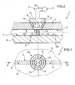
figure 1 is a diagrammatic top view, with details removed for clarity, of a micro-fluidic system made according to the present invention; -
figure 2 is a cross section along plane II-II of the microfluidic system offigure 1 ; -
figures 3 and 4 show details of the section offigure 2 in two different operative configurations; -
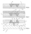
figure 5 is a section of a further embodiment of a micro-fluidic system made according to the present invention; -
figures 6 and 7 show two steps of the production of components of the micro-fluidic system offigure 5 ; -
figure 8 shows some components of the system offigures 9 and 10 ; -
figures 9 and 10 show details of a side section of an embodiment of a system produced according to the present invention; -
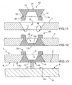
figures 11 and 12 show a step of assembling the components of the micro-fluidic system offigure 13 ; -
figure 13 shows details of a side section of an embodiment of a system produced according to the present invention; -
figure 14 shows a component of the system offigure 13 ; -
figures 15 and 16 show two steps of the production of components of the micro-fluidic system offigure 17 ; -
figure 17 shows details of a side section of an embodiment of a system produced according to the present invention; -
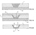
figures 18 and 19 show two steps of the production of components offigure 20 ; -
figure 20 shows components of the system offigure 1 ; and -
figures 21 and 22 show two steps of the production of the component offigure 14 . - In
figure 1 ,numeral 1 indicates as a whole a microfluidic system comprising amicro-fluidic channel 2 and avalve 3, which is adapted to adjust the transfer of fluid (in particular of liquid) from asegment 4 to a segment 5 (and/or vice versa) ofchannel 2. -
System 1 comprises asupport wall 6, which serves as bottom wall ofchannel 2; acovering wall 2, which serves as top wall ofchannel 2; and aspacer element 8, (shown partially) which sealingly connectswall 6 andwall 7 and defineschannel 2 laterally and at the ends (not shown). In particular,spacer element 8 comprises two end portions (not shown); and two side portions (partially shown infigure 1 ) which extend continuously, parallelly to the plane of the sheet offigure 2 , on opposite sides of end portions (not shown) so as to sealingly connectwall 6 andwall 7. The side portions are transversal (in particular, substantially perpendicular) and sealingly connected to the end portions (not shown). -
Wall 7 has ahole 9, which is arranged betweensegments channel 2 and are adapted to connectchannel 2 with further ducts/channels (not shown) ofsystem 1 or with the outside.Wall 7 has an inner surface IS partially delimiting channel 2 (in particular, on top). -
Segments channel 2 is substantially linear. - Inner surface IS extends (immediately) downstream and (immediately) upstream of
valve 3 so as to partially delimit (in particular on the top)micro-fluidic channel 2 in the area ofsegments segment 4 is substantially coplanar to (part of) inner surface IS present in the area of the second segment. - System 1 (in particular, wall 6) comprises an inner surface IS2, which substantially faces inner surface IS. More precisely, surfaces IS and IS2 are parallel to one another.
- Surface IS2 extends (immediately) downstream and (immediately) upstream of
valve 3 so as to partially delimit (in particular on the bottom)micro-fluidic channel 2 in the area ofsegments segment 4 is substantially coplanar to (part of) inner surface IS2 present in the area of the second segment. - According to some embodiments,
wall 6 is made of silicon;wall 7 is made of glass;spacer element 8 is made of a photoresist material. - By photoresist material there is intended a material obtained from an electromagnetic radiation (in particular, in the range of visible light and infrared) sensitive material which, if exposed to these electromagnetic radiations, may become soluble (in this case the photoresist material is a positive photoresist) or insoluble (in this case the photoresist material is a negative photoresist) in specific solvents (usually designated developer photoresists).
- According to some embodiments, the photoresist material is a negative photoresist.
- According to some embodiments, the photoresist material is selected from the group consisting of: acrylic polymer, polymethylglutarimide, at least partially crosslinked SU-8 and a mixture of diazonaphthoquinone with a phenolformaldehyde. In particular, the photoresist material is selected from the group consisting of: acrylic polymer, at least partially crosslinked SU-8.
- In the present text, by acrylic polymer there is intended a polymer obtained by the polymerisation of at least one acrylic monomer. In particular, by acrylic polymer there is intended a polymer obtained by the polymerisation of an acrylic monomer.
- The acrylic monomer is selected from alkyl esters of acrylic acid or of methacrylic acid, in which in particular the alkyl has one to six carbon atoms.
- According to some embodiments, the acrylic monomer is selected from the group consisting of: methylmethacrylate (MMA), ethylmethacrylate, propylmethacrylate, buthylmethacrilate, methylacrilate, ethylacrilate, buthylacrilate. Advantageously, the acrylic monomer is selected from the group consisting of: methylacrylate, ethylacrilate, butylacrilate. In particular, the acrylic polymer is a polymethylacrilate.
- Advantageously, the acrylic polymer is crosslinked.
- According to specific embodiments, the photoresist is obtained by treating Dryresist Ordyl SY300 of Elga Europe with light radiations.
- According to further embodiments,
wall 6,wall 7 andspacer element 8 may be made of materials other than those indicated above. -
Channel 2 has a section having an equivalent diameter from 10 µm to 0.5 mm. According to some embodiments, the section ofchannel 2 is substantially constant. -
Hole 9 has an equivalent diameter from 100 µm to 1 mm. Advantageously,hole 9 has an equivalent diameter from 200 µm to 1 mm. According to some embodiments,hole 9 has a diameter smaller than 0.5 mm. - The dimensions indicated in the present text may be measured in a standard manner with profilometers.
- According to some embodiments hole 9 has a shape selected from the group consisting of: substantially frusto-conical, substantially frusto-pyramidal, substantially parallelepipedal, substantially cylindrical. Advantageously, holes 9 have a substantially frusto-conical, substantially frusto-pyramidal (in particular substantially frusto-conical - as in the embodiment shown in
figures 1 and 2 ). -
Valve 3 includes aclosing element 10 comprising (in particular, consisting of) a substantially elastic material (in particular, an elastomer); and anactuator 11, which is adapted to displace closingelement 10 from a locked position (shown infigure 3 ) to an open position (shown infigure 4 ). - According to some embodiments,
actuator 11 comprises a suction system (in particular a pump). - According to some embodiments, closing
element 10 may consist of a single elastomeric material (i.e. an elastomer) or by a combination (for example a mixture) of several different elastomeric materials. - Advantageously, the elastomer comprises (in particular consists of) a silicone, in particular a silicone rubber. According to some embodiments, the silicone has the following formula:
[R2SiO]n
wherein n is an integer greater than 4, each R is selected, independently of the others, from the group consisting of: methyl, ethyl, propyl. - According to some embodiments the elastomer comprises (i.e. consists of) only one silicone or, alternatively, several different silicones.
- Advantageously, the elastomer has an elastic modulus from 750 KPa to 2500 KPa.
- Micro-fluidic system 1 (in particular, valve 3) further comprises a
partition 12 arranged withinmicro-fluidic channel 2 betweensegments partition 12 separatessegments Partition 12 projects from inner surface IS2 (in particular, towards hole 9). -
Partition 12 is adapted toseparate segments element 10 is in a locking configuration (figure 3 ), closingelement 10 is adapted to cooperate with (in particular is in contact with)partition 12 to sealingly isolatesegment 4 with respect tosegment 5. In particular, in the locked configuration, closingelement 10 is adapted to close on top the open ends ofsegments element 10 is in an open configuration (figure 4 ),partition 12 and closingelement 10 are spaced from one another, and the fluid (in particular the liquid) may pass fromsegment 4 to segment 5 (or vice versa) "overcoming"partition 12. - Advantageously,
partition 12 extends fromwall 6 for a height substantially equivalent to the distance betweenwalls hole 9. In this manner, in resting conditions (i.e. whenactuator 11 exerts neither a negative nor a positive pressure on closing element 10), closingelement 10 is in contact withpartition 12. - According to some advantageous embodiments,
partition 12 is connected (in particular is integral) withspacer element 8. Advantageously, (therefore)spacer element 8 andpartition 12 are of the same material. In particular,partition 12 is made of a photoresist material. - Closing
element 10 is connected towall 7 in the area ofhole 9 and has acontrast surface 13, which is in contact withpartition 12 and extends coplanar to said inner surface IS. - According to some embodiments, closing
element 10 comprises a closingportion 14, which hasopposition surface 13 and is deformable so as to move away frompartition 12 whenactuator 11shifts closing element 10 in the open configuration; and at least oneside portion 15 that extends from the edge of closingportion 14 outwards and along a delimitingsurface 16 of saidhole 9. Advantageously, closingportion 14 is substantially a membrane. - According to some embodiments,
side portion 15 extends along the peripheral edge of closingportion 14. - According to specific embodiments, closing
element 10 has a width from 700 µm to 2 mm; closingportion 14 has a thickness from 100 to 200 µm; theside portion 15 has a height from closingportion 14 from about 110 µm to about 700 µm - Advantageously,
side portion 15 extends up to at least one outer delimitingedge 17 ofhole 9. In particular,side portion 15 extends along (at least) thewhole delimiting surface 16 ofhole 9. - According to the embodiment shown in
figure 2 ,actuator 11 is a suction system (in particular a pump) and is sealingly connected tohole 9 by means of aduct 18. Advantageously, in use,actuator 11 exerts a positive pressure on closingelement 10 so as to push closingelement 10 against partition 12 (figure 3 - locked configuration). In this manner the sealing between closingelement 10 andpartition 12 is improved. - According to other embodiments, the actuator is a system that acts mechanically on closing
element 10. The mechanical action may be exerted by a rod 21 (for opening or closing) or by a piston (only for closing). The mechanical action may be determined in turn by an electromechanical system (such as for instance an electromagnet that determines a displacement of the rod or piston, or by a screw system connected to a motor), or by a purely mechanical system (such as a spring). - The actuator allows to switch between open valve and closed valve, according to one of the following methods or combination of methods:
- 1. closing:
- a. pneumatic, by means of a duct for creating a pressure on the outer side of the closing element;
- b. mechanical, by means of a rod or piston, for exerting a pressure on the closing element;
- c. by pre-tensioning closing
element 10, which determines a fluid-tight coupling withpartition 12;
- 2. opening:
- a. pneumatic (by means of a duct for creating a depression on the outer side of the closing element)
- b. mechanical (by means of a rod or piston, for exerting a depression on the closing element)
- c. by pre-tensioning closing
element 10, which determines, when resting, an outward deflection of the micro-fluidic channel, creating a path for the fluid abovepartition 12.
- When
segments actuator 11 is inverted. Actuator 11 (therefore) exerts a negative pressure (suction) on closingelement 10 so as to deform closingelement 10 and separate it from partition 12 (figure 4 - open configuration). Thereby,segments - According to some embodiments, closing
element 10 andwall 7 are connected to one another by one of the connections selected from the group consisting of: lock-joint, adhesive joint, opposition joint and a combination thereof. Advantageously, this connection is substantially tight fluid. - As shown for the embodiments of
figures 1-4 and17 ,side portion 15 and delimitingsurface 16 ofhole 9 are connected to one another by means of an adhesive connection. Advantageously, the adhesive connection is obtained by plasma treatment. According to some embodiments, the adhesive connection is obtained by the polymerisation or hardening (crosslinking) in situ (i.e. within hole.9) of an at least partially polymerisable or hardenable (crosslinkable) material to obtain closingelement 10. - The embodiment shown in
figure 17 duffers from the embodiment offigures 1-4 substantially in the shape of closingelement 10, which in this case has arelief portion 20 extending along the edge of closingportion 14.Portion 20 serves as a gasket and allows to improve the sealing connection withduct 18. - According to some embodiments (see for example
figure 13 ),side portion 15 has aseat 19 at an end thereof opposite to closingportion 14.Seat 19 is engaged by outer delimitingedge 17 ofhole 9 so as to define a lock-joint. - According to some embodiments, such as for example those shown in
figure 13 ,9 and 10 ,hole 9 is tapered bymicro-fluidic channel 2 outwards (in other words, it broadens inwards) so as to define an opposition joint together withside portion 15. In particular, it should be noted that closingelement 10 remains correctly withinhole 9 in virtue of the cooperation of delimitingsurface 16 andpartition 12. - In the variant shown in
figure 9 and 10 ,actuator 11 comprises an operatingrod 21 which has a head engaged in aseat 22 of closingelement 10. - It should be noted that, advantageously,
side portion 15 has a shape complementary to that ofhole 9 and in particular of delimitingsurface 16. -
System 1 according to the present invention has several advantages with respect to the state of the art. - In particular,
actuator 11 does not need to always be active. In this connection, it may be noted that the unusual geometry of system 1 (and in particular, of closingelement 10 and of partition 12) allows, in resting conditions (i.e. whenactuator 11 exerts neither a negative nor a positive pressure), closingelement 10 to cooperate withpartition 12 sufficiently as to isolatesegments element 10, the coupling between closingelement 10 andpartition 12 is particularly effective. - Another advantage of
system 1 according to the present invention is related to the coupling between closingelement 10 andwall 7 being particularly simple and stable. -
System 1 according to the present invention may advantageously be used in an apparatus for separating particles as for example disclosed in one of the following Italian patent applications and patent applications claiming the priority thereof:BO2009A000152 BO2009A000153 BO2009A000154 BO2009A000155 - Unless explicitly indicated otherwise, the content of the references (papers, texts, patent applications etc.) cited in this text is herein incorporated by way of completeness of description. In particular, the above mentioned references are herein incorporated by reference.
- Further features of the present invention will result from the following disclosure of some embodiments of
microfluidic system 1 given by mere way of non-limitative illustration. - This example discloses the production of closing
element 10 of the embodiment offigures 1-4 . - Closing
element 10 was made of PDMS (polydimethylsiloxane) (Sylgard 184® of Dow Corning - it should be noted however that other materials may be used). - The hardening agent of PDMS (polydimethylsiloxane) and the base are mixed in a ratio of 1:10 and the mixture obtained thereby was poured in a hole 9 (
figure 18 ) of acovering wall 7, whichhole 9 is closed on the bottom by abase mould 23. PDMS was degassed in a vacuum chamber for one hour. Alid 24 is arranged onhole 9 to remove PDMS in excess and configure closing element 10 (figure 19 ).Wall 7 is inserted in an oven for 2 hours at 80°C. Closing element 10 is therefore obtained already connected towall 7. - This example discloses an alternative embodiment of closing
element 10 of the embodiment offigures 1-4 . - Closing
element 10 was made of PDMS (polydimethylsiloxane) (Sylgard 184® of Dow Corning - it should be noted however that other materials may be used). - The hardening agent of PDMS (tetra methyl tetravinyl cyclotetrasiloxane) and the base were mixed in a ratio of 1:10 and the mixture obtained thereby was poured in a mould which reproduces the shape of closing
element 10 in negative. PDMS was degassed in a vacuum chamber for one hour. A lid was arranged on mould 26 to remove PDMS in excess. The covered mould was inserted in an oven for 2 hours at 80°C. Closing element 10 was then extracted from the mould by using a cutter. - Closing
element 10 andwall 7 are treated in a plasma reactor (Gambetti Plasma, Modello Tucano) by using the parameters of table 1 in O2/N2 mixture.Table 1 Plasma activation Power, W 40 Voltage, V 360 Pressure, mbar 0,3-0,4 Time, s 35 - Closing
element 10 was then introduced inhole 9 and was connected to delimitingsurface 16 by the mentioned plasma treatment. - This example discloses the production of closing
element 10 of the embodiment offigure 5 . - Closing
element 10 offigure 5 is obtained following the procedure disclosed in example 1 and using abase mould 23, alid 24 and awall 7 therefor as shown infigures 6 and 7 . - This example discloses the production of closing
element 10 of the embodiment offigure 17 . - Closing
element 10 offigure 17 is obtained following the procedure disclosed in example 1 and using abase mould 23, alid 24 and awall 7 therefor as shown infigures 15 and 16 . - This example discloses the production of closing
element 10 of the embodiment offigure 13 (or14 ). - The closing element of
figure 13 is obtained following the procedure disclosed in example 2 and using abase mould 23, alid 24 and anintermediate mould 25 therefor as shown infigures 6 and 7 . - The combination of closing
element 10 withcorresponding wall 7 forms a lock joint as shown infigures 11 and 12 . - This example discloses the implementation of
micro-fluidic system 1 shown infigures 1-4 . - A layer of photo-polymer (Dryresist in particular Ordyl SY300, Elga Europe) (thickness 90 µm) was laminated at a 90° angle on
support 6 of silicon (figure 11 ) (thickness 600 µm) The layer was therefore partially protected by a photolithographic mask (a transparent slide printed with a resolution of 24000 DPI) (figure 12 ) and subjected to UV radiation (150W) for 15 seconds so that the areas of the layer which are exposed (i.e. not covered by the dark parts of the mask) polymerise. Once polymerisation was selectively performed, the non polymerised part was removed by dippinglaminated substrate 6 in a developer (BMR developer - mixture of xylene, 2-butoxyethylacetate, mixture of isomers). - At this point,
wall 6 with the correspondingspacer element 8 andpartition 12 obtained thereby were heated in an oven at a temperature of 50°C for 1 hour to obtain drying. - A glass layer of wall 7 (thickness 500 µm) was obtained by milling.
Holes 9, and end holes have a frusto-conical shape with the bottom part having a diameter of 700 µm and the top part having a diameter of 1200 µm. - The mentioned glass layer was combined with closing
element 10 according to what has been disclosed in example 1. -
Wall 7 was pressed againstspacer element 8 for 80 minutes at a temperature of 95°C to obtain a thermal bond. - The procedure of example 6 was repeated for each combination of closing element 10 -
wall 7 disclosed in examples 2 to 5 so as to obtain respective micro-fluidic systems.
Claims (20)
- A micro-fluidic system comprising
at least one micro-fluidic channel (2), which in turn comprises a first segment (4), at least one second segment (5) and at least one wall (7), which is provided with at least one hole (9) arranged between the first and the second segment (4, 5) and has an inner surface (IS) at least partially delimiting the micro-fluidic channel (2);
and at least one valve (3), which is arranged along the microfluidic channel (2) in the area of the hole (9) and comprises an actuator (11), a closing element (10) comprising at least one substantially elastic material and a partition (12) arranged within the micro fluidic channel (2), between the first and the second segment (4, 5); the actuator is adapted to handle the closing element (10) between a locked configuration, in which the closing element (10) cooperates with the partition (12) so as to substantially isolate the first and the second segment (4, 5) from one another, and an open configuration, in which the first and the second segment (4, 5) are connected to one another;
the inner surface (IS) extends downstream and upstream of valve (3) so as to at least partially define the microfluidic channel (2) in the area of the first and second segment (4, 5);
the system (1) being characterised in that the closing element (10) is connected to the wall (7) in the area of the hole (9) and has an opposing surface (13), which, in the locked position, is in contact with the partition (12) and extends coplanar to said inner surface (IS). - The system according to claim 1, comprising a further inner surface (IS2), which substantially faces the inner surface (IS) and partially delimits the microfluidic channel (2) in the area of the first and second segment (4, 5) ; the partition (23) projects from the further inner surface (IS2) towards the hole (9) ; the inner surface (IS) in the area of the first segment (4) is substantially coplanar to the inner surface (IS) in the area of the second segment.
- The system according to claim 1 or 2, wherein the closing element (10) and the wall (7) have a substantially fluid-tight connection selected from the group consisting of: lock-joint, adhesive joint, opposition joint and a combination thereof.
- The system according to one of the preceding claims, wherein the closing element (10) comprises a closing portion (14), which has said opposing surface (13) and is deformable so as to move away from the partition (12) when the actuator (11) shifts the closing element (10) in the open configuration; and at least one side portion (15) that extends from the edge of the closing portion (10) outwards along a delimiting surface (16) of said hole (9).
- The system according to claim 4, wherein the closing portion (14) is substantially membrane-shaped; the side portion (15) extending up to at least one outer delimiting edge (17) of the hole (9); in particular, the side portion (15) extending along at least the whole of the delimiting surface (16).
- The system according to claim 4 or 5, wherein the side portion (15) and the delimiting surface (16) of the hole (9) are connected to one another by means of an adhesive joint.
- The system according to claim 6, wherein the adhesive joint is obtained by plasma treatment.
- The system according to any of claims 4 to 7, wherein the side portion (15) has a seat (19) at an end of the side portion (15) opposite to the closing portion (14), the seat (19) being engaged by an outer delimiting edge (17) of the hole (9) so as to define a lock-joint.
- The system according to any of the preceding claims, wherein the hole (9) is tapered from the micro-fluidic channel (2) outwards so as to define an opposition joint together with the side portion (15).
- The system according to any of claims 4 to 9, wherein the side portion (15) extends along the whole peripheral edge of the closing portion (14).
- The system according to any of the preceding claims, wherein the hole (9) has a shape selected from the group consisting of: substantially frusto-conical, substantially frusto-pyramidal.
- The system according to any of the preceding claims, wherein the micro-fluidic channel (2) has a section with an equivalent diameter greater than 10 µm.
- The system according to any of the preceding claims, wherein the hole (9) has an equivalent diameter smaller than 1 mm, in particular greater than 100 µm.
- The system according to any of the preceding claims, wherein the closing element (10) comprises, in particular consists of, at least one elastomer.
- The system according to claim 14, wherein the elastomer comprises a silicone, in particular a silicone rubber.
- The system according to claim 15, wherein the silicone has the following formula:
[R2SiO]n
wherein n is an integer greater than 4, each R is selected, independently of the others, from the group consisting of: methyl, ethyl, propyl. - The system according to any of the claims 14 to 16, wherein the elastomer has an elastic modulus from 750 KPa to 2500 KPa.
- The system according to any of the preceding claims, wherein the first and the second segment (4, 5) are substantially coplanar to one another; the partition (12) separating the first and the second segment (4, 5).
- The system according to any of the preceding claims, wherein the inner surface (IS) in the area of the first segment (4) is substantially coplanar to the inner surface (IS) in the area of the second segment.
- The system according to any of the preceding claims, wherein said actuator (11) allows to switch between open valve and closed valve, according to one of the following methods or combinations thereof:I. closing:a. pneumatic, by means of a duct for creating a pressure on the outer side of the closing element;b. mechanical, by means of a rod or piston, for exerting a pressure on the closing element;c. by pre-tensioning the closing element (10), which determines a fluid-tight coupling thereof with the partition (12);II. opening:d. pneumatic (by means of a duct for creating a depression on the outer side of the closing element);e. mechanical (by means of a rod or piston, for exerting a depression on the closing element);f. by pre-tensioning the closing element (10), which determines, when resting, an outward deflection with respect to the micro-fluidic channel, creating a path for the fluid above the partition (12).
Applications Claiming Priority (2)
| Application Number | Priority Date | Filing Date | Title |
|---|---|---|---|
| ITBO2009A000808A IT1397820B1 (en) | 2009-12-17 | 2009-12-17 | MICROFLUID SYSTEM |
| PCT/IB2010/003280 WO2011073784A1 (en) | 2009-12-17 | 2010-12-16 | Micro-fluidic system |
Publications (2)
| Publication Number | Publication Date |
|---|---|
| EP2513535A1 EP2513535A1 (en) | 2012-10-24 |
| EP2513535B1 true EP2513535B1 (en) | 2015-10-28 |
Family
ID=42543338
Family Applications (1)
| Application Number | Title | Priority Date | Filing Date |
|---|---|---|---|
| EP10818088.6A Active EP2513535B1 (en) | 2009-12-17 | 2010-12-16 | Micro-fluidic system |
Country Status (6)
| Country | Link |
|---|---|
| US (1) | US10060554B2 (en) |
| EP (1) | EP2513535B1 (en) |
| DK (1) | DK2513535T3 (en) |
| ES (1) | ES2560462T3 (en) |
| IT (1) | IT1397820B1 (en) |
| WO (1) | WO2011073784A1 (en) |
Families Citing this family (4)
| Publication number | Priority date | Publication date | Assignee | Title |
|---|---|---|---|---|
| IT1403518B1 (en) | 2010-12-22 | 2013-10-31 | Silicon Biosystems Spa | MICROFLUID DEVICE FOR PARTICLE HANDLING |
| WO2015083829A1 (en) * | 2013-12-06 | 2015-06-11 | 国立大学法人東京大学 | Valve, fluid-controlling structure, fluid device, and method for manufacturing valve |
| JP6881453B2 (en) * | 2016-07-13 | 2021-06-02 | 株式会社ニコン | Fluid devices, manufacturing methods for fluid devices, and valves for fluid devices |
| GB2555816A (en) * | 2016-11-10 | 2018-05-16 | Natural Environment Res Council | Analyser |
Family Cites Families (24)
| Publication number | Priority date | Publication date | Assignee | Title |
|---|---|---|---|---|
| US5309943A (en) * | 1992-12-07 | 1994-05-10 | Ford Motor Company | Micro-valve and method of manufacturing |
| US5967163A (en) * | 1996-01-30 | 1999-10-19 | Abbott Laboratories | Actuator and method |
| US5932799A (en) * | 1997-07-21 | 1999-08-03 | Ysi Incorporated | Microfluidic analyzer module |
| WO1999017749A1 (en) * | 1997-10-02 | 1999-04-15 | Iep Group, Inc. | A micromachined valve for fluid applications |
| US6908770B1 (en) * | 1998-07-16 | 2005-06-21 | Board Of Regents, The University Of Texas System | Fluid based analysis of multiple analytes by a sensor array |
| DE19949912C2 (en) * | 1999-10-16 | 2003-02-27 | Karlsruhe Forschzent | Force transmission device, method for its production and its use |
| DE10048376C2 (en) * | 2000-09-29 | 2002-09-19 | Fraunhofer Ges Forschung | Micro valve with a normally closed state |
| WO2002029106A2 (en) * | 2000-10-03 | 2002-04-11 | California Institute Of Technology | Microfluidic devices and methods of use |
| DE10239597B4 (en) * | 2002-08-28 | 2005-03-17 | Fresenius Medical Care Deutschland Gmbh | disposable cartridge |
| WO2004061085A2 (en) * | 2002-12-30 | 2004-07-22 | The Regents Of The University Of California | Methods and apparatus for pathogen detection and analysis |
| US7284966B2 (en) * | 2003-10-01 | 2007-10-23 | Agency For Science, Technology & Research | Micro-pump |
| US7438030B1 (en) * | 2005-08-26 | 2008-10-21 | The United States Of America As Represented By The Administrator Of The National Aeronautics And Space Administration | Actuator operated microvalves |
| US7862000B2 (en) * | 2006-02-03 | 2011-01-04 | California Institute Of Technology | Microfluidic method and structure with an elastomeric gas-permeable gasket |
| EP1905514A1 (en) * | 2006-09-30 | 2008-04-02 | Roche Diagnostics GmbH | Device having a reversibly closable fluid valve |
| KR20100028526A (en) | 2007-02-05 | 2010-03-12 | 마이크로칩 바이오테크놀로지스, 인크. | Microfluidic and nanofluidic devices, systems, and applications |
| DE102007035721B4 (en) * | 2007-07-30 | 2019-02-07 | Robert Bosch Gmbh | Microvalve, method of manufacturing a microvalve and micropump |
| PT2408562T (en) | 2009-03-17 | 2018-06-06 | Menarini Silicon Biosystems Spa | Microfluidic device for isolation of cells |
| ITBO20090154A1 (en) | 2009-03-17 | 2010-09-18 | Silicon Biosystems Spa | MICROFLUID SYSTEM |
| ITBO20090155A1 (en) | 2009-03-17 | 2010-09-18 | Silicon Biosystems Spa | METHOD FOR INSULATING PARTICLES |
| EP2438154A1 (en) * | 2009-06-02 | 2012-04-11 | Integenx Inc. | Fluidic devices with diaphragm valves |
| IT1397819B1 (en) * | 2009-12-17 | 2013-02-04 | Silicon Biosystems Spa | MICROFLUID SYSTEM |
| IT1398480B1 (en) * | 2009-12-17 | 2013-03-01 | Silicon Biosystems Spa | MICROFLUID SYSTEM |
| KR20110136629A (en) * | 2010-06-15 | 2011-12-21 | 삼성전자주식회사 | Microfluidic device with micro valve |
| US20130032235A1 (en) * | 2011-08-02 | 2013-02-07 | Teledyne Dalsa Semiconductor, Inc. | Integrated microfluidic check valve and device including such a check valve |
-
2009
- 2009-12-17 IT ITBO2009A000808A patent/IT1397820B1/en active
-
2010
- 2010-12-16 EP EP10818088.6A patent/EP2513535B1/en active Active
- 2010-12-16 US US13/516,087 patent/US10060554B2/en active Active
- 2010-12-16 WO PCT/IB2010/003280 patent/WO2011073784A1/en not_active Ceased
- 2010-12-16 ES ES10818088.6T patent/ES2560462T3/en active Active
- 2010-12-16 DK DK10818088.6T patent/DK2513535T3/en active
Also Published As
| Publication number | Publication date |
|---|---|
| WO2011073784A1 (en) | 2011-06-23 |
| DK2513535T3 (en) | 2016-01-25 |
| ES2560462T3 (en) | 2016-02-19 |
| EP2513535A1 (en) | 2012-10-24 |
| IT1397820B1 (en) | 2013-02-04 |
| ITBO20090808A1 (en) | 2011-06-18 |
| US10060554B2 (en) | 2018-08-28 |
| US20130037139A1 (en) | 2013-02-14 |
Similar Documents
| Publication | Publication Date | Title |
|---|---|---|
| US9127783B2 (en) | Micro-fluidic system | |
| US10060554B2 (en) | Micro-fluidic system | |
| EP1331997B1 (en) | Microfluidic flow control devices | |
| US20110315227A1 (en) | Microfluidic system and method | |
| US6644944B2 (en) | Uni-directional flow microfluidic components | |
| KR101274113B1 (en) | Magnetic microvalve using metal ball and manufacturing method thereof | |
| WO2008043046A2 (en) | Microfluidic check valves | |
| EP2438154A1 (en) | Fluidic devices with diaphragm valves | |
| WO2002085522A1 (en) | Microfluidic device with partially restrained element | |
| AU2004276302A1 (en) | Photocurable perfluoropolyethers for use as novel materials in microfluidic devices | |
| EP2513534B1 (en) | Micro-fluidic system | |
| US6811695B2 (en) | Microfluidic filter | |
| Ryu et al. | Precision patterning of PDMS thin films: a new fabrication method and its applications | |
| KR20080090410A (en) | Fine line bonding and/or sealing system and method | |
| CN112253843B (en) | High leakproofness microvalve based on photocuring 3D prints preparation | |
| CN113769798A (en) | Microfluidic Chip | |
| RU2824465C1 (en) | Precision-calibrated check valve for microfluidic systems | |
| WO2014030958A1 (en) | Method for preparing thin-film chip replica and microfluidic chip prepared by using the method | |
| AU2019387109A1 (en) | Thermoplastic forming tools, assemblages thereof, and methods of making and methods of use thereof | |
| Pallandre et al. | New ‘monolithic’templates and improved protocols for soft lithography and microchip fabrication | |
| Simone et al. | Fabrication and characterization of a hybrid valve for microfluidic applications | |
| US20080110516A1 (en) | Check valve | |
| Yang et al. | Microfabricated PDMS Check Valves | |
| Perdigones et al. | Integration of polydimethylsiloxane membranes in SU-8 structures | |
| Roy et al. | Thermoplastics elastomers for microfluidics valving and mixing, toward highthroughput fabrication of multilayers devices |
Legal Events
| Date | Code | Title | Description |
|---|---|---|---|
| PUAI | Public reference made under article 153(3) epc to a published international application that has entered the european phase |
Free format text: ORIGINAL CODE: 0009012 |
|
| 17P | Request for examination filed |
Effective date: 20120619 |
|
| AK | Designated contracting states |
Kind code of ref document: A1 Designated state(s): AL AT BE BG CH CY CZ DE DK EE ES FI FR GB GR HR HU IE IS IT LI LT LU LV MC MK MT NL NO PL PT RO RS SE SI SK SM TR |
|
| DAX | Request for extension of the european patent (deleted) | ||
| GRAJ | Information related to disapproval of communication of intention to grant by the applicant or resumption of examination proceedings by the epo deleted |
Free format text: ORIGINAL CODE: EPIDOSDIGR1 |
|
| GRAP | Despatch of communication of intention to grant a patent |
Free format text: ORIGINAL CODE: EPIDOSNIGR1 |
|
| GRAP | Despatch of communication of intention to grant a patent |
Free format text: ORIGINAL CODE: EPIDOSNIGR1 |
|
| INTG | Intention to grant announced |
Effective date: 20150504 |
|
| GRAS | Grant fee paid |
Free format text: ORIGINAL CODE: EPIDOSNIGR3 |
|
| GRAA | (expected) grant |
Free format text: ORIGINAL CODE: 0009210 |
|
| AK | Designated contracting states |
Kind code of ref document: B1 Designated state(s): AL AT BE BG CH CY CZ DE DK EE ES FI FR GB GR HR HU IE IS IT LI LT LU LV MC MK MT NL NO PL PT RO RS SE SI SK SM TR |
|
| REG | Reference to a national code |
Ref country code: GB Ref legal event code: FG4D |
|
| REG | Reference to a national code |
Ref country code: CH Ref legal event code: EP |
|
| REG | Reference to a national code |
Ref country code: AT Ref legal event code: REF Ref document number: 758141 Country of ref document: AT Kind code of ref document: T Effective date: 20151115 |
|
| REG | Reference to a national code |
Ref country code: IE Ref legal event code: FG4D |
|
| REG | Reference to a national code |
Ref country code: DE Ref legal event code: R096 Ref document number: 602010028661 Country of ref document: DE |
|
| REG | Reference to a national code |
Ref country code: FR Ref legal event code: PLFP Year of fee payment: 6 |
|
| REG | Reference to a national code |
Ref country code: DK Ref legal event code: T3 Effective date: 20160120 |
|
| REG | Reference to a national code |
Ref country code: CH Ref legal event code: NV Representative=s name: HEPP WENGER RYFFEL AG, CH |
|
| REG | Reference to a national code |
Ref country code: SE Ref legal event code: TRGR |
|
| REG | Reference to a national code |
Ref country code: ES Ref legal event code: FG2A Ref document number: 2560462 Country of ref document: ES Kind code of ref document: T3 Effective date: 20160219 |
|
| REG | Reference to a national code |
Ref country code: LT Ref legal event code: MG4D |
|
| REG | Reference to a national code |
Ref country code: NL Ref legal event code: FP |
|
| PG25 | Lapsed in a contracting state [announced via postgrant information from national office to epo] |
Ref country code: IS Free format text: LAPSE BECAUSE OF FAILURE TO SUBMIT A TRANSLATION OF THE DESCRIPTION OR TO PAY THE FEE WITHIN THE PRESCRIBED TIME-LIMIT Effective date: 20160228 Ref country code: HR Free format text: LAPSE BECAUSE OF FAILURE TO SUBMIT A TRANSLATION OF THE DESCRIPTION OR TO PAY THE FEE WITHIN THE PRESCRIBED TIME-LIMIT Effective date: 20151028 Ref country code: NO Free format text: LAPSE BECAUSE OF FAILURE TO SUBMIT A TRANSLATION OF THE DESCRIPTION OR TO PAY THE FEE WITHIN THE PRESCRIBED TIME-LIMIT Effective date: 20160128 Ref country code: LT Free format text: LAPSE BECAUSE OF FAILURE TO SUBMIT A TRANSLATION OF THE DESCRIPTION OR TO PAY THE FEE WITHIN THE PRESCRIBED TIME-LIMIT Effective date: 20151028 |
|
| PG25 | Lapsed in a contracting state [announced via postgrant information from national office to epo] |
Ref country code: LV Free format text: LAPSE BECAUSE OF FAILURE TO SUBMIT A TRANSLATION OF THE DESCRIPTION OR TO PAY THE FEE WITHIN THE PRESCRIBED TIME-LIMIT Effective date: 20151028 Ref country code: FI Free format text: LAPSE BECAUSE OF FAILURE TO SUBMIT A TRANSLATION OF THE DESCRIPTION OR TO PAY THE FEE WITHIN THE PRESCRIBED TIME-LIMIT Effective date: 20151028 Ref country code: RS Free format text: LAPSE BECAUSE OF FAILURE TO SUBMIT A TRANSLATION OF THE DESCRIPTION OR TO PAY THE FEE WITHIN THE PRESCRIBED TIME-LIMIT Effective date: 20151028 Ref country code: GR Free format text: LAPSE BECAUSE OF FAILURE TO SUBMIT A TRANSLATION OF THE DESCRIPTION OR TO PAY THE FEE WITHIN THE PRESCRIBED TIME-LIMIT Effective date: 20160129 Ref country code: PL Free format text: LAPSE BECAUSE OF FAILURE TO SUBMIT A TRANSLATION OF THE DESCRIPTION OR TO PAY THE FEE WITHIN THE PRESCRIBED TIME-LIMIT Effective date: 20151028 Ref country code: PT Free format text: LAPSE BECAUSE OF FAILURE TO SUBMIT A TRANSLATION OF THE DESCRIPTION OR TO PAY THE FEE WITHIN THE PRESCRIBED TIME-LIMIT Effective date: 20160229 |
|
| PG25 | Lapsed in a contracting state [announced via postgrant information from national office to epo] |
Ref country code: CZ Free format text: LAPSE BECAUSE OF FAILURE TO SUBMIT A TRANSLATION OF THE DESCRIPTION OR TO PAY THE FEE WITHIN THE PRESCRIBED TIME-LIMIT Effective date: 20151028 Ref country code: LU Free format text: LAPSE BECAUSE OF FAILURE TO SUBMIT A TRANSLATION OF THE DESCRIPTION OR TO PAY THE FEE WITHIN THE PRESCRIBED TIME-LIMIT Effective date: 20151216 Ref country code: MC Free format text: LAPSE BECAUSE OF FAILURE TO SUBMIT A TRANSLATION OF THE DESCRIPTION OR TO PAY THE FEE WITHIN THE PRESCRIBED TIME-LIMIT Effective date: 20151028 |
|
| REG | Reference to a national code |
Ref country code: DE Ref legal event code: R097 Ref document number: 602010028661 Country of ref document: DE |
|
| REG | Reference to a national code |
Ref country code: CH Ref legal event code: PFA Owner name: MENARINI SILICON BIOSYSTEMS S.P.A., IT Free format text: FORMER OWNER: SILICON BIOSYSTEMS S.P.A., IT |
|
| PG25 | Lapsed in a contracting state [announced via postgrant information from national office to epo] |
Ref country code: SK Free format text: LAPSE BECAUSE OF FAILURE TO SUBMIT A TRANSLATION OF THE DESCRIPTION OR TO PAY THE FEE WITHIN THE PRESCRIBED TIME-LIMIT Effective date: 20151028 Ref country code: SM Free format text: LAPSE BECAUSE OF FAILURE TO SUBMIT A TRANSLATION OF THE DESCRIPTION OR TO PAY THE FEE WITHIN THE PRESCRIBED TIME-LIMIT Effective date: 20151028 Ref country code: EE Free format text: LAPSE BECAUSE OF FAILURE TO SUBMIT A TRANSLATION OF THE DESCRIPTION OR TO PAY THE FEE WITHIN THE PRESCRIBED TIME-LIMIT Effective date: 20151028 Ref country code: RO Free format text: LAPSE BECAUSE OF FAILURE TO SUBMIT A TRANSLATION OF THE DESCRIPTION OR TO PAY THE FEE WITHIN THE PRESCRIBED TIME-LIMIT Effective date: 20151028 |
|
| REG | Reference to a national code |
Ref country code: DE Ref legal event code: R082 Ref document number: 602010028661 Country of ref document: DE Representative=s name: VOSSIUS & PARTNER PATENTANWAELTE RECHTSANWAELT, DE Ref country code: DE Ref legal event code: R081 Ref document number: 602010028661 Country of ref document: DE Owner name: MENARINI SILICON BIOSYSTEMS S.P.A., IT Free format text: FORMER OWNER: SILICON BIOSYSTEMS S.P.A., BOLOGNA, IT |
|
| PLBE | No opposition filed within time limit |
Free format text: ORIGINAL CODE: 0009261 |
|
| STAA | Information on the status of an ep patent application or granted ep patent |
Free format text: STATUS: NO OPPOSITION FILED WITHIN TIME LIMIT |
|
| 26N | No opposition filed |
Effective date: 20160729 |
|
| REG | Reference to a national code |
Ref country code: NL Ref legal event code: HC Owner name: MENARINI SILICON BIOSYSTEMS S.P.A.; IT Free format text: DETAILS ASSIGNMENT: VERANDERING VAN EIGENAAR(S), VERANDERING VAN NAAM VAN DE EIGENAAR(S); FORMER OWNER NAME: SILICON BIOSYSTEMS S.P.A. Effective date: 20160808 |
|
| REG | Reference to a national code |
Ref country code: ES Ref legal event code: PC2A Owner name: MENARINI SILICON BIOSYSTEMS S.P.A. Effective date: 20161018 |
|
| REG | Reference to a national code |
Ref country code: FR Ref legal event code: PLFP Year of fee payment: 7 |
|
| PG25 | Lapsed in a contracting state [announced via postgrant information from national office to epo] |
Ref country code: SI Free format text: LAPSE BECAUSE OF FAILURE TO SUBMIT A TRANSLATION OF THE DESCRIPTION OR TO PAY THE FEE WITHIN THE PRESCRIBED TIME-LIMIT Effective date: 20151028 |
|
| REG | Reference to a national code |
Ref country code: FR Ref legal event code: CA Effective date: 20161108 Ref country code: FR Ref legal event code: CD Owner name: MENARINI SILICON BIOSYSTEMS S.P.A., IT Effective date: 20161108 |
|
| REG | Reference to a national code |
Ref country code: AT Ref legal event code: HC Ref document number: 758141 Country of ref document: AT Kind code of ref document: T Owner name: MENARINI SILICON BIOSYSTEMS S.P.A., IT Effective date: 20170329 |
|
| PG25 | Lapsed in a contracting state [announced via postgrant information from national office to epo] |
Ref country code: HU Free format text: LAPSE BECAUSE OF FAILURE TO SUBMIT A TRANSLATION OF THE DESCRIPTION OR TO PAY THE FEE WITHIN THE PRESCRIBED TIME-LIMIT; INVALID AB INITIO Effective date: 20101216 Ref country code: BG Free format text: LAPSE BECAUSE OF FAILURE TO SUBMIT A TRANSLATION OF THE DESCRIPTION OR TO PAY THE FEE WITHIN THE PRESCRIBED TIME-LIMIT Effective date: 20151028 |
|
| PG25 | Lapsed in a contracting state [announced via postgrant information from national office to epo] |
Ref country code: CY Free format text: LAPSE BECAUSE OF FAILURE TO SUBMIT A TRANSLATION OF THE DESCRIPTION OR TO PAY THE FEE WITHIN THE PRESCRIBED TIME-LIMIT Effective date: 20151028 |
|
| PG25 | Lapsed in a contracting state [announced via postgrant information from national office to epo] |
Ref country code: MT Free format text: LAPSE BECAUSE OF FAILURE TO SUBMIT A TRANSLATION OF THE DESCRIPTION OR TO PAY THE FEE WITHIN THE PRESCRIBED TIME-LIMIT Effective date: 20151028 |
|
| REG | Reference to a national code |
Ref country code: FR Ref legal event code: PLFP Year of fee payment: 8 |
|
| PG25 | Lapsed in a contracting state [announced via postgrant information from national office to epo] |
Ref country code: TR Free format text: LAPSE BECAUSE OF FAILURE TO SUBMIT A TRANSLATION OF THE DESCRIPTION OR TO PAY THE FEE WITHIN THE PRESCRIBED TIME-LIMIT Effective date: 20151028 Ref country code: MK Free format text: LAPSE BECAUSE OF FAILURE TO SUBMIT A TRANSLATION OF THE DESCRIPTION OR TO PAY THE FEE WITHIN THE PRESCRIBED TIME-LIMIT Effective date: 20151028 |
|
| PG25 | Lapsed in a contracting state [announced via postgrant information from national office to epo] |
Ref country code: AL Free format text: LAPSE BECAUSE OF FAILURE TO SUBMIT A TRANSLATION OF THE DESCRIPTION OR TO PAY THE FEE WITHIN THE PRESCRIBED TIME-LIMIT Effective date: 20151028 |
|
| REG | Reference to a national code |
Ref country code: AT Ref legal event code: UEP Ref document number: 758141 Country of ref document: AT Kind code of ref document: T Effective date: 20151028 |
|
| P01 | Opt-out of the competence of the unified patent court (upc) registered |
Effective date: 20230518 |
|
| PGFP | Annual fee paid to national office [announced via postgrant information from national office to epo] |
Ref country code: DK Payment date: 20241224 Year of fee payment: 15 |
|
| PGFP | Annual fee paid to national office [announced via postgrant information from national office to epo] |
Ref country code: NL Payment date: 20241224 Year of fee payment: 15 Ref country code: BE Payment date: 20241224 Year of fee payment: 15 |
|
| PGFP | Annual fee paid to national office [announced via postgrant information from national office to epo] |
Ref country code: GB Payment date: 20241217 Year of fee payment: 15 |
|
| PGFP | Annual fee paid to national office [announced via postgrant information from national office to epo] |
Ref country code: FR Payment date: 20241227 Year of fee payment: 15 |
|
| PGFP | Annual fee paid to national office [announced via postgrant information from national office to epo] |
Ref country code: AT Payment date: 20241218 Year of fee payment: 15 |
|
| PGFP | Annual fee paid to national office [announced via postgrant information from national office to epo] |
Ref country code: IE Payment date: 20241218 Year of fee payment: 15 |
|
| PGFP | Annual fee paid to national office [announced via postgrant information from national office to epo] |
Ref country code: IT Payment date: 20241125 Year of fee payment: 15 |
|
| PGFP | Annual fee paid to national office [announced via postgrant information from national office to epo] |
Ref country code: SE Payment date: 20241224 Year of fee payment: 15 |
|
| PGFP | Annual fee paid to national office [announced via postgrant information from national office to epo] |
Ref country code: DE Payment date: 20241227 Year of fee payment: 15 |
|
| PGFP | Annual fee paid to national office [announced via postgrant information from national office to epo] |
Ref country code: ES Payment date: 20250113 Year of fee payment: 15 |
|
| PGFP | Annual fee paid to national office [announced via postgrant information from national office to epo] |
Ref country code: CH Payment date: 20250101 Year of fee payment: 15 |